EP0330909A2 - Process for mounting parts on a printed-circuit board - Google Patents
Process for mounting parts on a printed-circuit board Download PDFInfo
- Publication number
- EP0330909A2 EP0330909A2 EP89102571A EP89102571A EP0330909A2 EP 0330909 A2 EP0330909 A2 EP 0330909A2 EP 89102571 A EP89102571 A EP 89102571A EP 89102571 A EP89102571 A EP 89102571A EP 0330909 A2 EP0330909 A2 EP 0330909A2
- Authority
- EP
- European Patent Office
- Prior art keywords
- adhesive
- circuit board
- weight
- printed circuit
- light
- Prior art date
- Legal status (The legal status is an assumption and is not a legal conclusion. Google has not performed a legal analysis and makes no representation as to the accuracy of the status listed.)
- Granted
Links
Images

Classifications
-
- H—ELECTRICITY
- H01—ELECTRIC ELEMENTS
- H01L—SEMICONDUCTOR DEVICES NOT COVERED BY CLASS H10
- H01L24/00—Arrangements for connecting or disconnecting semiconductor or solid-state bodies; Methods or apparatus related thereto
- H01L24/80—Methods for connecting semiconductor or other solid state bodies using means for bonding being attached to, or being formed on, the surface to be connected
- H01L24/83—Methods for connecting semiconductor or other solid state bodies using means for bonding being attached to, or being formed on, the surface to be connected using a layer connector
-
- H—ELECTRICITY
- H01—ELECTRIC ELEMENTS
- H01L—SEMICONDUCTOR DEVICES NOT COVERED BY CLASS H10
- H01L24/00—Arrangements for connecting or disconnecting semiconductor or solid-state bodies; Methods or apparatus related thereto
- H01L24/01—Means for bonding being attached to, or being formed on, the surface to be connected, e.g. chip-to-package, die-attach, "first-level" interconnects; Manufacturing methods related thereto
- H01L24/26—Layer connectors, e.g. plate connectors, solder or adhesive layers; Manufacturing methods related thereto
- H01L24/28—Structure, shape, material or disposition of the layer connectors prior to the connecting process
- H01L24/29—Structure, shape, material or disposition of the layer connectors prior to the connecting process of an individual layer connector
-
- H—ELECTRICITY
- H05—ELECTRIC TECHNIQUES NOT OTHERWISE PROVIDED FOR
- H05K—PRINTED CIRCUITS; CASINGS OR CONSTRUCTIONAL DETAILS OF ELECTRIC APPARATUS; MANUFACTURE OF ASSEMBLAGES OF ELECTRICAL COMPONENTS
- H05K3/00—Apparatus or processes for manufacturing printed circuits
- H05K3/30—Assembling printed circuits with electric components, e.g. with resistor
- H05K3/303—Surface mounted components, e.g. affixing before soldering, aligning means, spacing means
- H05K3/305—Affixing by adhesive
-
- H—ELECTRICITY
- H01—ELECTRIC ELEMENTS
- H01L—SEMICONDUCTOR DEVICES NOT COVERED BY CLASS H10
- H01L2224/00—Indexing scheme for arrangements for connecting or disconnecting semiconductor or solid-state bodies and methods related thereto as covered by H01L24/00
- H01L2224/01—Means for bonding being attached to, or being formed on, the surface to be connected, e.g. chip-to-package, die-attach, "first-level" interconnects; Manufacturing methods related thereto
- H01L2224/26—Layer connectors, e.g. plate connectors, solder or adhesive layers; Manufacturing methods related thereto
- H01L2224/28—Structure, shape, material or disposition of the layer connectors prior to the connecting process
- H01L2224/29—Structure, shape, material or disposition of the layer connectors prior to the connecting process of an individual layer connector
- H01L2224/29001—Core members of the layer connector
- H01L2224/29099—Material
- H01L2224/2919—Material with a principal constituent of the material being a polymer, e.g. polyester, phenolic based polymer, epoxy
-
- H—ELECTRICITY
- H01—ELECTRIC ELEMENTS
- H01L—SEMICONDUCTOR DEVICES NOT COVERED BY CLASS H10
- H01L2224/00—Indexing scheme for arrangements for connecting or disconnecting semiconductor or solid-state bodies and methods related thereto as covered by H01L24/00
- H01L2224/80—Methods for connecting semiconductor or other solid state bodies using means for bonding being attached to, or being formed on, the surface to be connected
- H01L2224/83—Methods for connecting semiconductor or other solid state bodies using means for bonding being attached to, or being formed on, the surface to be connected using a layer connector
- H01L2224/8319—Arrangement of the layer connectors prior to mounting
-
- H—ELECTRICITY
- H01—ELECTRIC ELEMENTS
- H01L—SEMICONDUCTOR DEVICES NOT COVERED BY CLASS H10
- H01L2224/00—Indexing scheme for arrangements for connecting or disconnecting semiconductor or solid-state bodies and methods related thereto as covered by H01L24/00
- H01L2224/80—Methods for connecting semiconductor or other solid state bodies using means for bonding being attached to, or being formed on, the surface to be connected
- H01L2224/83—Methods for connecting semiconductor or other solid state bodies using means for bonding being attached to, or being formed on, the surface to be connected using a layer connector
- H01L2224/838—Bonding techniques
- H01L2224/8385—Bonding techniques using a polymer adhesive, e.g. an adhesive based on silicone, epoxy, polyimide, polyester
-
- H—ELECTRICITY
- H01—ELECTRIC ELEMENTS
- H01L—SEMICONDUCTOR DEVICES NOT COVERED BY CLASS H10
- H01L2924/00—Indexing scheme for arrangements or methods for connecting or disconnecting semiconductor or solid-state bodies as covered by H01L24/00
- H01L2924/01—Chemical elements
- H01L2924/01004—Beryllium [Be]
-
- H—ELECTRICITY
- H01—ELECTRIC ELEMENTS
- H01L—SEMICONDUCTOR DEVICES NOT COVERED BY CLASS H10
- H01L2924/00—Indexing scheme for arrangements or methods for connecting or disconnecting semiconductor or solid-state bodies as covered by H01L24/00
- H01L2924/01—Chemical elements
- H01L2924/01005—Boron [B]
-
- H—ELECTRICITY
- H01—ELECTRIC ELEMENTS
- H01L—SEMICONDUCTOR DEVICES NOT COVERED BY CLASS H10
- H01L2924/00—Indexing scheme for arrangements or methods for connecting or disconnecting semiconductor or solid-state bodies as covered by H01L24/00
- H01L2924/01—Chemical elements
- H01L2924/01006—Carbon [C]
-
- H—ELECTRICITY
- H01—ELECTRIC ELEMENTS
- H01L—SEMICONDUCTOR DEVICES NOT COVERED BY CLASS H10
- H01L2924/00—Indexing scheme for arrangements or methods for connecting or disconnecting semiconductor or solid-state bodies as covered by H01L24/00
- H01L2924/01—Chemical elements
- H01L2924/01013—Aluminum [Al]
-
- H—ELECTRICITY
- H01—ELECTRIC ELEMENTS
- H01L—SEMICONDUCTOR DEVICES NOT COVERED BY CLASS H10
- H01L2924/00—Indexing scheme for arrangements or methods for connecting or disconnecting semiconductor or solid-state bodies as covered by H01L24/00
- H01L2924/01—Chemical elements
- H01L2924/01014—Silicon [Si]
-
- H—ELECTRICITY
- H01—ELECTRIC ELEMENTS
- H01L—SEMICONDUCTOR DEVICES NOT COVERED BY CLASS H10
- H01L2924/00—Indexing scheme for arrangements or methods for connecting or disconnecting semiconductor or solid-state bodies as covered by H01L24/00
- H01L2924/01—Chemical elements
- H01L2924/01018—Argon [Ar]
-
- H—ELECTRICITY
- H01—ELECTRIC ELEMENTS
- H01L—SEMICONDUCTOR DEVICES NOT COVERED BY CLASS H10
- H01L2924/00—Indexing scheme for arrangements or methods for connecting or disconnecting semiconductor or solid-state bodies as covered by H01L24/00
- H01L2924/01—Chemical elements
- H01L2924/0102—Calcium [Ca]
-
- H—ELECTRICITY
- H01—ELECTRIC ELEMENTS
- H01L—SEMICONDUCTOR DEVICES NOT COVERED BY CLASS H10
- H01L2924/00—Indexing scheme for arrangements or methods for connecting or disconnecting semiconductor or solid-state bodies as covered by H01L24/00
- H01L2924/01—Chemical elements
- H01L2924/01032—Germanium [Ge]
-
- H—ELECTRICITY
- H01—ELECTRIC ELEMENTS
- H01L—SEMICONDUCTOR DEVICES NOT COVERED BY CLASS H10
- H01L2924/00—Indexing scheme for arrangements or methods for connecting or disconnecting semiconductor or solid-state bodies as covered by H01L24/00
- H01L2924/01—Chemical elements
- H01L2924/01033—Arsenic [As]
-
- H—ELECTRICITY
- H01—ELECTRIC ELEMENTS
- H01L—SEMICONDUCTOR DEVICES NOT COVERED BY CLASS H10
- H01L2924/00—Indexing scheme for arrangements or methods for connecting or disconnecting semiconductor or solid-state bodies as covered by H01L24/00
- H01L2924/01—Chemical elements
- H01L2924/01052—Tellurium [Te]
-
- H—ELECTRICITY
- H01—ELECTRIC ELEMENTS
- H01L—SEMICONDUCTOR DEVICES NOT COVERED BY CLASS H10
- H01L2924/00—Indexing scheme for arrangements or methods for connecting or disconnecting semiconductor or solid-state bodies as covered by H01L24/00
- H01L2924/01—Chemical elements
- H01L2924/01056—Barium [Ba]
-
- H—ELECTRICITY
- H01—ELECTRIC ELEMENTS
- H01L—SEMICONDUCTOR DEVICES NOT COVERED BY CLASS H10
- H01L2924/00—Indexing scheme for arrangements or methods for connecting or disconnecting semiconductor or solid-state bodies as covered by H01L24/00
- H01L2924/01—Chemical elements
- H01L2924/01068—Erbium [Er]
-
- H—ELECTRICITY
- H01—ELECTRIC ELEMENTS
- H01L—SEMICONDUCTOR DEVICES NOT COVERED BY CLASS H10
- H01L2924/00—Indexing scheme for arrangements or methods for connecting or disconnecting semiconductor or solid-state bodies as covered by H01L24/00
- H01L2924/01—Chemical elements
- H01L2924/01074—Tungsten [W]
-
- H—ELECTRICITY
- H01—ELECTRIC ELEMENTS
- H01L—SEMICONDUCTOR DEVICES NOT COVERED BY CLASS H10
- H01L2924/00—Indexing scheme for arrangements or methods for connecting or disconnecting semiconductor or solid-state bodies as covered by H01L24/00
- H01L2924/01—Chemical elements
- H01L2924/01077—Iridium [Ir]
-
- H—ELECTRICITY
- H01—ELECTRIC ELEMENTS
- H01L—SEMICONDUCTOR DEVICES NOT COVERED BY CLASS H10
- H01L2924/00—Indexing scheme for arrangements or methods for connecting or disconnecting semiconductor or solid-state bodies as covered by H01L24/00
- H01L2924/01—Chemical elements
- H01L2924/01082—Lead [Pb]
-
- H—ELECTRICITY
- H01—ELECTRIC ELEMENTS
- H01L—SEMICONDUCTOR DEVICES NOT COVERED BY CLASS H10
- H01L2924/00—Indexing scheme for arrangements or methods for connecting or disconnecting semiconductor or solid-state bodies as covered by H01L24/00
- H01L2924/013—Alloys
- H01L2924/014—Solder alloys
-
- H—ELECTRICITY
- H01—ELECTRIC ELEMENTS
- H01L—SEMICONDUCTOR DEVICES NOT COVERED BY CLASS H10
- H01L2924/00—Indexing scheme for arrangements or methods for connecting or disconnecting semiconductor or solid-state bodies as covered by H01L24/00
- H01L2924/06—Polymers
- H01L2924/0665—Epoxy resin
-
- H—ELECTRICITY
- H01—ELECTRIC ELEMENTS
- H01L—SEMICONDUCTOR DEVICES NOT COVERED BY CLASS H10
- H01L2924/00—Indexing scheme for arrangements or methods for connecting or disconnecting semiconductor or solid-state bodies as covered by H01L24/00
- H01L2924/06—Polymers
- H01L2924/078—Adhesive characteristics other than chemical
- H01L2924/07802—Adhesive characteristics other than chemical not being an ohmic electrical conductor
-
- H—ELECTRICITY
- H01—ELECTRIC ELEMENTS
- H01L—SEMICONDUCTOR DEVICES NOT COVERED BY CLASS H10
- H01L2924/00—Indexing scheme for arrangements or methods for connecting or disconnecting semiconductor or solid-state bodies as covered by H01L24/00
- H01L2924/10—Details of semiconductor or other solid state devices to be connected
- H01L2924/11—Device type
- H01L2924/14—Integrated circuits
-
- H—ELECTRICITY
- H01—ELECTRIC ELEMENTS
- H01L—SEMICONDUCTOR DEVICES NOT COVERED BY CLASS H10
- H01L2924/00—Indexing scheme for arrangements or methods for connecting or disconnecting semiconductor or solid-state bodies as covered by H01L24/00
- H01L2924/19—Details of hybrid assemblies other than the semiconductor or other solid state devices to be connected
- H01L2924/1901—Structure
- H01L2924/1904—Component type
- H01L2924/19041—Component type being a capacitor
-
- H—ELECTRICITY
- H01—ELECTRIC ELEMENTS
- H01L—SEMICONDUCTOR DEVICES NOT COVERED BY CLASS H10
- H01L2924/00—Indexing scheme for arrangements or methods for connecting or disconnecting semiconductor or solid-state bodies as covered by H01L24/00
- H01L2924/19—Details of hybrid assemblies other than the semiconductor or other solid state devices to be connected
- H01L2924/1901—Structure
- H01L2924/1904—Component type
- H01L2924/19043—Component type being a resistor
-
- H—ELECTRICITY
- H05—ELECTRIC TECHNIQUES NOT OTHERWISE PROVIDED FOR
- H05K—PRINTED CIRCUITS; CASINGS OR CONSTRUCTIONAL DETAILS OF ELECTRIC APPARATUS; MANUFACTURE OF ASSEMBLAGES OF ELECTRICAL COMPONENTS
- H05K2201/00—Indexing scheme relating to printed circuits covered by H05K1/00
- H05K2201/10—Details of components or other objects attached to or integrated in a printed circuit board
- H05K2201/10613—Details of electrical connections of non-printed components, e.g. special leads
- H05K2201/10621—Components characterised by their electrical contacts
- H05K2201/10636—Leadless chip, e.g. chip capacitor or resistor
-
- H—ELECTRICITY
- H05—ELECTRIC TECHNIQUES NOT OTHERWISE PROVIDED FOR
- H05K—PRINTED CIRCUITS; CASINGS OR CONSTRUCTIONAL DETAILS OF ELECTRIC APPARATUS; MANUFACTURE OF ASSEMBLAGES OF ELECTRICAL COMPONENTS
- H05K2203/00—Indexing scheme relating to apparatus or processes for manufacturing printed circuits covered by H05K3/00
- H05K2203/05—Patterning and lithography; Masks; Details of resist
- H05K2203/0502—Patterning and lithography
- H05K2203/0508—Flood exposure
-
- Y—GENERAL TAGGING OF NEW TECHNOLOGICAL DEVELOPMENTS; GENERAL TAGGING OF CROSS-SECTIONAL TECHNOLOGIES SPANNING OVER SEVERAL SECTIONS OF THE IPC; TECHNICAL SUBJECTS COVERED BY FORMER USPC CROSS-REFERENCE ART COLLECTIONS [XRACs] AND DIGESTS
- Y02—TECHNOLOGIES OR APPLICATIONS FOR MITIGATION OR ADAPTATION AGAINST CLIMATE CHANGE
- Y02P—CLIMATE CHANGE MITIGATION TECHNOLOGIES IN THE PRODUCTION OR PROCESSING OF GOODS
- Y02P70/00—Climate change mitigation technologies in the production process for final industrial or consumer products
- Y02P70/50—Manufacturing or production processes characterised by the final manufactured product
-
- Y—GENERAL TAGGING OF NEW TECHNOLOGICAL DEVELOPMENTS; GENERAL TAGGING OF CROSS-SECTIONAL TECHNOLOGIES SPANNING OVER SEVERAL SECTIONS OF THE IPC; TECHNICAL SUBJECTS COVERED BY FORMER USPC CROSS-REFERENCE ART COLLECTIONS [XRACs] AND DIGESTS
- Y10—TECHNICAL SUBJECTS COVERED BY FORMER USPC
- Y10T—TECHNICAL SUBJECTS COVERED BY FORMER US CLASSIFICATION
- Y10T29/00—Metal working
- Y10T29/49—Method of mechanical manufacture
- Y10T29/49002—Electrical device making
- Y10T29/49117—Conductor or circuit manufacturing
- Y10T29/49124—On flat or curved insulated base, e.g., printed circuit, etc.
- Y10T29/4913—Assembling to base an electrical component, e.g., capacitor, etc.
- Y10T29/49144—Assembling to base an electrical component, e.g., capacitor, etc. by metal fusion
-
- Y—GENERAL TAGGING OF NEW TECHNOLOGICAL DEVELOPMENTS; GENERAL TAGGING OF CROSS-SECTIONAL TECHNOLOGIES SPANNING OVER SEVERAL SECTIONS OF THE IPC; TECHNICAL SUBJECTS COVERED BY FORMER USPC CROSS-REFERENCE ART COLLECTIONS [XRACs] AND DIGESTS
- Y10—TECHNICAL SUBJECTS COVERED BY FORMER USPC
- Y10T—TECHNICAL SUBJECTS COVERED BY FORMER US CLASSIFICATION
- Y10T29/00—Metal working
- Y10T29/49—Method of mechanical manufacture
- Y10T29/49002—Electrical device making
- Y10T29/49117—Conductor or circuit manufacturing
- Y10T29/49124—On flat or curved insulated base, e.g., printed circuit, etc.
- Y10T29/4913—Assembling to base an electrical component, e.g., capacitor, etc.
- Y10T29/49146—Assembling to base an electrical component, e.g., capacitor, etc. with encapsulating, e.g., potting, etc.
Definitions
- the invention relates to a method for fastening components on a printed circuit board by applying a photoactivatable adhesive to predetermined areas of the components or the printed circuit board, equipping the printed circuit board with the components, hardening the adhesive connection at a temperature between 60 and 140 ° C. and producing soldered connections between the components and the circuit board.
- Such a method is known from DE-PS 29 04 649.
- SMT Surface Mounted Technology
- electronic components such as capacitors, resistors and the like are attached to printed circuit boards, for example printed circuit boards, printed circuits, hybrid ICs and the like, using a photo-activatable adhesive, the adhesive connection being used primarily for this purpose , the components as long as on the circuit board to hold firmly until the solder connections between the components and the circuit board have been made.
- UV-curable resins are used as adhesives, which contain a proportion of polymerizable monomers, photosensitizers, initiators and optionally a number of fillers.
- UV-curable acrylic resins cure quickly in the light-accessible areas, but require a second curing mechanism to cure shaded areas, especially where they are hidden by the components, which is caused by thermal polymerization initiators and requires high temperatures.
- thermal polymerization initiators and requires high temperatures.
- the higher the temperature load on the electronic components the lower their statistical life expectancy.
- the UV-curable adhesives used in the known method are also sensitive to atmospheric oxygen. Furthermore, the strong coloration of the drop of adhesive often required for chip adhesives can reduce the penetration depth of the UV radiation, thus preventing complete curing and later leading to signs of corrosion.
- EP-A-0 182 744 discloses photocurable, filler-containing epoxy resin compositions which contain at least one photoinitiator of the metallocene type and which can be used, inter alia, for sticking active and passive components of microelectronics onto printed circuit boards, provided the masses are electrical contain conductive fillers.
- the UV-induced photo-curing is optionally followed by a thermal post-curing.
- EP-A-0 279 199 (republished) describes a method and a device for processing UV-curable reaction resin compositions, in which the UV-curable reaction resin composition is irradiated in the application device and fed directly to a substrate or a casting mold.
- JP-A-61-98740 also describes the production of molding and coating compositions using a UV-preactivated resin matrix.
- a method for fastening components on a printed circuit board is also not mentioned.
- the invention has for its object to provide a method for fastening components, in particular SMD's (Surface Mounted Devices), on a printed circuit board, with which it is possible to cure the adhesive used in a shorter time and at lower temperatures than in the known methods to leave, but without reducing the wetting capacity of the adhesive during assembly of the circuit board.
- SMD's Surface Mounted Devices
- This object is achieved according to the invention in a method of the type mentioned at the outset in that the adhesive is activated by irradiation with light of a wavelength in the range from 200 to 600 nm before the circuit board is fitted, to the extent that the desired initial tack is retained and no skin formation occurs the adhesive surface occurs.
- the initial stickiness of the activated adhesive allows the printed circuit board to be transported to the place where the thermal connection of the adhesive connection takes place after the components have been fitted.
- the person skilled in the art can easily determine on the basis of simple preliminary tests how great the initial stickiness, which depends on the type and material of the components and the printed circuit board, must be.
- the initial stickiness must in any case be so great that the components do not move on the printed circuit board during transport from the assembly station to the station in which the thermal curing of the adhesive takes place, i.e. they do not change their exactly predetermined position.
- the process according to the invention has the advantage that photo-activatable one-component compositions are used to fasten the components which have a high storage stability but polymerize very quickly at low temperatures after activation. Due to the longevity of the activated species generated in the exposure step, it is possible to expose the masses used before placing the components.
- the disadvantage of an uncured adhesive layer in shaded zones which has occurred in the prior art cannot therefore occur in the method according to the invention. Both stages of curing, that is to say both the UV-induced activation and the thermal curing, take place uniformly through the entire applied adhesive layer in the method according to the invention, irrespective of whether this is covered by a component after assembly or is freely accessible and visible.
- the method according to the invention also has the following advantages: Low volatility, viscosity and low toxic potential of the monomers that can be used, - no inhibition of the reaction by atmospheric oxygen and therefore no smear layer, - excellent adhesion to different substrates, - excellent chemical and physical properties of the adhesive layer, - quick and easy activation and then extremely fast curing time at low curing temperatures, - high storage stability of the non-activated masses, - The strength of the adhesive bond is sufficient to hold the components immovably firmly on the circuit board until the completion of the soldered connections, but on the other hand - in contrast to conductive adhesive connections - it is not so large that the components cannot be retrofitted, e.g. during a repair, without Risk of damage could be removed.
- the activation step by adjusting the exposure time, the energy dose of the actinic lamps used and the wavelength range of the light used in such a way that on the one hand enough reactive species are produced for the subsequent rapid curing, but on the other hand no polymerization on the Surface takes place with the formation of a skin that prevents good wetting of the components and would therefore make the adhesive unsuitable.
- a superficial polymer layer occurs with all known masses of the prior art which have hitherto been used for gluing components onto printed circuit boards and at least partially below Radiation should harden.
- exposure is no longer necessary, as a result of which shadowing by the component or the printed circuit boards can no longer have a disruptive effect. Due to the activation of the adhesive used prior to the assembly, the subsequent heat curing is accelerated to such an extent that it takes place much faster than with the previously known heat-curable adhesives which were used to bond components to printed circuit boards.
- the UV-induced activation of the adhesive can either be after the application of the adhesive layer on the printed circuit board or on the surface of the component to be bonded or even before the application of the adhesive, for example in the application device, for example a dispenser, by irradiation with Light of a wavelength in the range of 200 to 600 nm can be carried out. If the activation takes place before the adhesive is applied, it is preferably carried out within a period of 1 sec. To 10 min., Preferably within a period of 1 min., Before the start of the adhesive application to the printed circuit board or the component.
- the intensity and duration of the exposure is preferably selected so that the preactivated adhesive has practically no change in viscosity before application for a period of at least 1 minute to preferably at least 5 minutes, particularly preferably up to at least 20 minutes, which significantly reduces the desired initial tack would cause a disruptive skin formation on the adhesive surface.
- Advantageous embodiments of the method according to the invention consist in that the activation of the adhesive takes place by irradiation with light with a wavelength of 300 to 500 nm for a period of 0.5 to 300 seconds and that the adhesive bond is hardened after the assembly the printed circuit board takes up to 15 minutes.
- the activation of the adhesive is carried out with daylight or daylight devices, preferably with a wavelength of 400 to 600 nm, particularly preferably 400 to 500 nm.
- the adhesive strength of the adhesive connection achieved in this way is in any case It is great that it withstands the mechanical stress during the subsequent soldering process, in particular in a wave or trailing solder bath, without further ado, and at the same time with an optimally low temperature load on the electronic components.
- Advantageous further developments of the method according to the invention further consist in that a cationically curable adhesive mass which is flowable before activation and has a viscosity of 0.05 to 1000 Pa.s is used as the photoactivatable adhesive.
- a good compromise between processability and the wetting properties of the adhesive compositions used is achieved with a viscosity of these compositions, measured before their activation, of 0.1 to 500 Pa.s, with a range of 0.4 to 200 Pa.s being special has advantageously shown.
- the resins and / or monomers polymerizing according to a radical polymerization mechanism preferably consist of the acrylic acid and / or methacrylic acid esters of mono- or polyhydric alcohols, the acrylic acid and / or methacrylic acid esters of polyhydric alcohols being particularly preferred.
- Mono or polyfunctional vinyl ethers and vinyl esters are suitable as cationically curable resins or cationically polymerizable monomers for use in the process according to the invention.
- Suitable vinyl ethers are trimethylolpropane trivinyl ether, ethylene glycol divinyl ether and cyclic vinyl ether. Triethylene glycol divinyl ether is particularly suitable.
- Cationically polymerizable heterocyclic compounds for example epoxides
- epoxides are also very suitable.
- the glycidyl ethers of mono- and polyhydric alcohols are preferably used here, for example the diglycidyl ethers of bisphenol-A.
- the di- and polyepoxides of cycloaliphatic compounds for example the glycidyl ether and ⁇ -methylglycidyl ether of cycloaliphatic diols and polyols, are particularly suitable for setting a high reactivity.
- glycidyl compounds are the glycidyl esters of carboxylic acids, in particular di- and polycarboxylic acids, for example the glycidyl esters of succinic acid, adipic acid, phthalic acid.
- Examples of particularly reactive glycidyl compounds are the diepoxides of vinylcyclohexane and dicyclopentadiene as well as 3- (3 ′, 4′-epoxycyclohexyl) -8,9-epoxy-2,4-dioxyspiro (5.5) undecane and 3,4-epoxycyclohexylmethyl-3 ′ , 4'-epoxycyclohexyl carboxylate.
- Preferred epoxy resins are optionally pre-extended and / or prepolymeric diglycidyl ethers of dihydric phenols or dihydric aliphatic alcohols with two to four C atoms.
- the pre-extended diglycidyl ethers of 2,2-bis (4-hydroxyphenyl) propane are particularly preferably used.
- Suitable photoinitiators which form Lewis or Bronsted acids when exposed to light are, in general, the photoinitiators known for cationic polymerization, for example aryldiazonium salts, diaryliodonium salts, triarylsulfonium salts and metallocene-like complex salts.
- a class of photoinitiators preferred for the purposes of the invention are the metallocene complex salts known from EP-A-0 182 744, in particular the compounds (Ia) and (Ib):
- Another preferred class of photoinitiators for cationic polymerization are the diaryl iodonium salts of the formula: Ar2J+X ⁇ , wherein Ar is an optionally substituted arene, for example benzene, toluene, xylene, ethylbenzene, methoxybenzene, naphthalene, 1,2-dihydronaphthalene, phenanthrene, anthracene, 9,10-dihydroanthracene, diphenylene, biphenyl, cumene; and wherein X ⁇ is a complex anion, for example BF4-, PF6 ⁇ , AsF6 ⁇ , SbF6 ⁇ , preferably BF4 ⁇ or PF6 ⁇ .
- Ar is an optionally substituted arene, for example benzene, toluene, xylene, ethylbenzene, methoxybenzene, naphthalene, 1,2-dihydronaphthalene
- Diphenyl iodonium tetrafluoroborate, ditoluyl iodonium tetrafluoroborate, ditoluyl iodonium hexafluorophosphate and di-t-butylphenyl iodonium tetrafluoroborate are particularly preferred.
- Further suitable diaryl iodonium salts can be found, for example, in "UV-Curing", Science and Technology, Ed. by S. Peter Pappas, Technology Marketing Corporation, Norwalk, USA 06851 (1980).
- the diaryl iodonium salts are preferably used together with photoinitiators which generate free radicals under the action of light.
- Powders of aluminum oxide, silicon dioxide, calcium carbonate, titanium dioxide, barium sulfate, mica and the like can be contained as fillers in the adhesive compositions used according to the invention, while powdered silicon dioxide with a specific surface area of 50 to 450 m 2 / g can preferably be contained as a thixotropic agent.
- the fillers used are preferably silanized.
- the silane coupling agents known per se for example ⁇ -methacryloyloxypropyltrimethoxysilane and glycidyloxypropyltrimethoxysilane, can be used as silanizing agents.
- compositions used according to the invention are for example peroxides, sensitizers such as e.g. Anthracene, pigments, dyes, antioxidants and the like.
- the sequence of stages A and B is interchanged, that is to say the activation of the adhesive composition by irradiation with actinic light is already carried out before the adhesive is applied either to the printed circuit board 1 or to the underside of the component 4.
- a resin composition is obtained by uniformly mixing 100 parts by weight of 3,4-epoxycyclohexylmethyl-3 ′, 4′-epoxycyclohexylcarboxylate, 3 parts by weight of ( ⁇ 5-2,4-cyclopentadien-1-yl) - [(1, 2,3,4,5,6-) - (1-methylethyl) -benzene] -iron (1 +) - hexafluorophosphate (1-) (Irgacure® 261 from Ciba-Geigy) and 6 parts by weight in powder form hydrophobized silicon dioxide with a specific surface area of 71 m 2 / g and a particle size smaller than 100 nm (Silica R-202 from Degussa).
- the resin composition has a viscosity of 1.7 Pa.s (Haake viscometer Rotovisko RV 100, PKI 0.5 / 28, 10% D).
- the resin composition is then applied to a printed circuit board in the form of a stable drop of adhesive between the contact terminals by means of a dispenser.
- the drop of adhesive has a ratio between diameter and height of approx. 2: 1.
- an irradiation device which emits actinic light in the range from 400 to 500 nm (Curelight 01 from Precon, light output approx. 100 mW / cm2).
- the printed circuit board equipped in this way is then placed in a drag soldering bath (Zevatron type EFT-1).
- the circuit board is moved at maximum speed level 10 into a container heated to 250 ° C. with molten solder and left immersed for 10 seconds in order to solder the electrode parts of the SOT housing to the connection connections using the solder.
- a perfectly soldered component is obtained.
- the immersion is repeated 5 times without the SOT housing detaching from the printed circuit board.
- Example 1 The resin composition of Example 1 is mixed with an additional 2 parts by weight of silanized silicon dioxide (R-202, from Degussa) and stirred into a homogeneous mixture.
- R-202 silanized silicon dioxide
- the resin composition has a viscosity of 2.8 Pa.s (Haake viscometer Rotovisko RV 100, PKI 0.5 / 28, 10% D).
- the sample is measured immediately after irradiation with the infrared lamp (conditions as in Example 1) on a universal testing device (Zwick 1435).
- the strength of the connection between the cylindrical components and the printed circuit board is determined by shearing off the printed circuit board (feed speed of the stamp 1 mm / min.). An average force of 46 N is required to shear the component. Since the area of the adhesive drop is 4 mm2, an average shear strength of 11.5 N / mm2 (MPa) can be determined.
- a common thermosetting one-component epoxy adhesive for the attachment of SMD components to printed circuit boards (Heraeus RD 860002 M) is applied to the same printed circuit board as in Example 2 using a dispenser.
- a cylindrical SMD resistor (Melf) is then applied to it and the circuit board is then left in a heating cabinet to harden the adhesive layer according to the manufacturing instructions (convection oven 120 ° C., 3 minutes).
- the printed circuit board is measured on a universal testing machine (Zwick 1435).
- the cylindrical SMD component is stamped at a feed rate of 1 mm / min. sheared. This requires a force of 41 N on average, from which the area of the adhesive drop of 5 mm2 is used to calculate an average shear strength of 8.2 N / mm2 (MPa).
- the shear strengths obtained with the commercially available preparation are poorer in spite of drastic curing conditions (3 minutes at 120 ° C. instead of 1 minute at 72 ° C.).
- a resin composition is obtained by uniformly mixing 80 parts by weight of 3,4-epoxycyclohexylmethyl-3 ′, 4′-epoxycyclohexylcarboxylate, 20 parts by weight of a cationically curable resin (UVR 6351 from Union Carbide), 3 parts by weight.
- a cationically curable resin UVR 6351 from Union Carbide
- Parts of Irgacure® 26i from Ciba-Geigy
- the viscosity is 1.0 Pa.s (Haake viscometer Rotovisko RV 100, PKI 0.5 / 28, 10% D).
- This resin composition is then applied to a printed circuit board using a dispenser.
- the drop of adhesive is irradiated with an ultraviolet radiation source (UVAHAND 200 from Dr. Höhnle GmbH, emitted light from 315 to 600 nm) at a distance of 10 cm, which corresponds to a UVA irradiance of 15 mW / cm2.
- UVAHAND 200 from Dr. Höhnle GmbH, emitted light from 315 to 600 nm
- the irradiation time is 30 seconds.
- a transistor in the SOT-23 housing is applied to the activated adhesive drop and the printed circuit board is irradiated for 2 minutes with an infrared lamp (IR drying attachment YTCO1L from Sartorius, 250 W), at a temperature of 80 ° C is reached.
- IR drying attachment YTCO1L from Sartorius, 250 W
- the resulting populated printed circuit board is moved in a drag soldering bath (Zevatron type EFT-1, maximum speed level 10) into a container heated to 250 ° C. with molten solder and left immersed for 10 seconds. There is no detachment of the transistor in the SOT-23 housing from the printed circuit board, and a perfectly soldered component is obtained.
- a drag soldering bath Zevatron type EFT-1, maximum speed level 10.
- a resin composition is obtained by uniformly mixing 100 parts by weight of a bisphenol A diepoxide (GY 259 from Ciba-Geigy), 3 parts by weight of Irgacure® 261 (from Ciba-Geigy) and 2.5 Parts by weight of cumene hydroperoxide.
- GY 259 from Ciba-Geigy
- Irgacure® 261 from Ciba-Geigy
- the resin composition has a viscosity of 11 Pa.s (Haake viscometer Rotovisko RV 100, PKI 0.5 / 28, 10% D).
- the same sample as in Example 1 is produced with this resin composition, with the only exception that instead of the SOT housing, a cuboidal electrolytic capacitor (15 D from Philips) is bonded.
- the sample is immediately after irradiation with the infrared lamp (under Conditions as mentioned in Example 1) in a drag soldering bath (from Zevatron type EFT-1).
- the circuit board is moved at speed level 4 into a container heated to 250 ° C. with molten solder and left immersed for 5 seconds. There is no detachment of the Elco housing from the printed circuit board during soldering. The soldering is flawless.
- a resin composition is obtained by uniformly mixing 50 parts by weight of 3,4-epoxycyclohexylmethyl-3 ′, 4′epoxycyclohexylcarboxylate, 50 parts by weight of triethylene glycol divinyl ether, 4 parts by weight of ethylene glycol, 3 parts by weight of bis- (4- methylphenyl) iodonium hexafluorophosphate, 1 part by weight of bis- (2,6-dichlorobenzoyl) -4-n-propylphenylphosphine oxide and 3 parts by weight of powdered hydrophobic silicon dioxide with a specific surface area of 71 m2 / g and a particle size of less than 100 nm (Silica R-202 from Degussa).
- the resin composition has a viscosity of 0.05 Pa.s (Haake viscometer Rotovisko RV 100, PKI 0.5 / 28, 10% D).
- the resin composition is then applied to a printed circuit board in the form of a drop of adhesive between the contact terminals with the aid of a dispenser.
- the drop of adhesive is then activated for 20 seconds using an irradiation device which emits actinic light in the range from 400 to 500 nm (Curelight 01 from Precon, approx. 100 mW / cm2).
- the resulting printed circuit board is then placed in a drag soldering bath (Zevatron type EFT-1).
- the circuit board is moved at speed level 4 into a container of molten solder heated to 250 ° C. and left immersed for 3 seconds. There is no detachment of the Elco housing from the printed circuit board during soldering. The soldering is perfectly fine.
- the resulting printed circuit board is then placed in a drag soldering bath (Zevatron type EFT-1).
- the circuit board is moved at speed level 4 into a container of molten solder heated to 250 ° C. and left immersed for 3 seconds.
- the SMD component detaches from the printed circuit board.
- the common one-component epoxy adhesive is not suitable under these mild curing conditions (1 minute thermal curing at 72 ° C) for bonding SMD components.
- a common one-component epoxy adhesive for attaching SMD components to printed circuit boards (Amicon D-124-F from Emerson and Cuming) is applied to a printed circuit board as described in Comparative Example 2 and cured under the same conditions and tested in a soldering bath .
- This common one-component epoxy adhesive is not suitable as an SMD adhesive under these mild curing conditions.
- a resin composition is obtained by uniformly mixing 100 parts by weight of 3,4-epoxycyclohexylmethyl-3 ′, 4′-epoxycyclohexylcarboxylate, 2.5 parts by weight of cumene hydroperoxide, 3 parts by weight of Irgacure® 261 (from Ciba- Geigy) and 3 parts by weight of hydrophobized silicon dioxide powder with a specific surface area of 71 m 2 / g and average particle size of less than 100 nm (R-202 from Degussa) with stirring.
- the resin composition has a viscosity of 0.95 Pa.s (Haake viscometer Rotovisko RV 100, PKI 0.5 / 28, 10% D).
- an irradiation device which emits actinic light in the range from 400 to 500 nm (Curelight 01 from Precon, approx. 100 mW / cm2) for 15 seconds.
- the resulting printed circuit board is then placed in a drag soldering bath (Zevatron type EFT-1).
- the circuit board is moved at maximum speed level 10 into a container heated to 250 ° C. with molten solder and left immersed for 3 seconds. There is no detachment of the SMD component from the printed circuit board during the soldering. The soldering is flawless.
- the immersion is repeated 3 times. There is no detachment of the SMD component from the printed circuit board.
- a common one-component epoxy adhesive for attaching SMD components to printed circuit boards is applied to an SMD component (D7508G from NEC) using a pen, as in Example 6, and then irradiated for 5 minutes with the same infrared lamp as in Example 6.
- the resulting populated circuit board is then inserted into the molten solder container under the same conditions as in Example 6.
- the SMD component detaches from the circuit board.
- This common one-component epoxy adhesive is not suitable under these mild curing conditions (5 minutes of thermal curing at 72 ° C) for the bonding of SMD parts.
Abstract
Description
Die Erfindung betrifft ein Verfahren zum Befestigen von Bauteilen auf einer Leiterplatte durch Auftragen eines photoaktivierbaren Klebstoffs auf vorbestimmte Flächen der Bauteile oder der Leiterplatte, Bestücken der Leiterplatte mit den Bauteilen, Härten der Klebeverbindung bei einer Temperatur zwischen 60 und 140°C sowie Herstellung von Lötverbindungen zwischen den Bauteilen und der Leiterplatte.The invention relates to a method for fastening components on a printed circuit board by applying a photoactivatable adhesive to predetermined areas of the components or the printed circuit board, equipping the printed circuit board with the components, hardening the adhesive connection at a temperature between 60 and 140 ° C. and producing soldered connections between the components and the circuit board.
Ein solches Verfahren ist aus der DE-PS 29 04 649 bekannt. Dabei werden nach der sogenannten "Surface Mounted Technology (SMT)" elektronische Bauteile wie Kondensatoren, Widerstände und dergleichen auf Leiterplatten, z.B. Printplatten, gedruckten Schaltungen, Hybrid-IC's und dergleichen unter Verwendung eines photoaktivierbaren Klebstoffs befestigt, wobei die Klebeverbindung in erster Linie dazu dient, die Bauteile solange auf der Leiterplatte unverrückbar festzuhalten, bis die Lötverbindungen zwischen den Bauteilen und der Leiterplatte hergestellt worden sind.Such a method is known from DE-PS 29 04 649. According to the so-called "Surface Mounted Technology (SMT)", electronic components such as capacitors, resistors and the like are attached to printed circuit boards, for example printed circuit boards, printed circuits, hybrid ICs and the like, using a photo-activatable adhesive, the adhesive connection being used primarily for this purpose , the components as long as on the circuit board to hold firmly until the solder connections between the components and the circuit board have been made.
Bei dem bekannten Verfahren werden als Klebstoffe UV-härtbare Harze verwendet, die einen Anteil an polymerisierbaren Monomeren, Photosensibilisatoren, Initiatoren sowie gegebenenfalls eine Reihe von Füllstoffen enthalten.In the known method, UV-curable resins are used as adhesives, which contain a proportion of polymerizable monomers, photosensitizers, initiators and optionally a number of fillers.
Diese UV-härtbaren Acrylatharze härten an den lichtzugänglichen Stellen rasch aus, bedürfen aber zur Aushärtung abgeschatteter Bereiche, also vor allem dort, wo sie durch die Bauteile verdeckt sind, eines zweiten Härtungsmechanismus, der durch Initiatoren der thermischen Polymerisation bewirkt wird und hohe Temperaturen erfordert. Je höher aber die Temperaturbelastung der elektronischen Bauelemente ist, um so geringer ist ihre statistische Lebenserwartung.These UV-curable acrylic resins cure quickly in the light-accessible areas, but require a second curing mechanism to cure shaded areas, especially where they are hidden by the components, which is caused by thermal polymerization initiators and requires high temperatures. However, the higher the temperature load on the electronic components, the lower their statistical life expectancy.
Es wurde deshalb bereits versucht, die Temperaturbelastung bei der thermischen Aushärtung der Klebemassen dadurch zu senken, daß pro Bauteil mindestens zwei Klebstoffpunkte zur Hälfte unter und zur Hälfte direkt neben das Bauteil gesetzt wurden, um so den Aushärtungsgrad in der ersten, UV-induzierten Härtungsstufe zu erhöhen. Integrierte Schaltkreise (Chips) mit rings um das Gehäuse angeordneten Anschlußbeinchen haben jedoch keinen freien Raum für solche Klebstofftropfen-Hälften.Attempts have therefore already been made to reduce the thermal load during the thermal curing of the adhesives by placing at least two adhesive dots half underneath and half directly next to the component per component in order to increase the degree of curing in the first, UV-induced curing stage increase. Integrated circuits (chips) with connection pins arranged all around the housing, however, have no free space for such adhesive drop halves.
Die bei dem bekannten Verfahren verwendeten UV-härtbaren Klebstoffe sind außerdem gegenüber atmosphärischem Sauerstoff empfindlich. Ferner kann die bei Chip-Klebstoffen oft geforderte starke Einfärbung des Klebstofftropfens die Eindringtiefe der UV-Strahlung vermindern, die vollständige Aushärtung somit verhindern und später zu Korrosionserscheinungen führen.The UV-curable adhesives used in the known method are also sensitive to atmospheric oxygen. Furthermore, the strong coloration of the drop of adhesive often required for chip adhesives can reduce the penetration depth of the UV radiation, thus preventing complete curing and later leading to signs of corrosion.
Aus der EP-A-0 182 744 sind photohärtbare, Füllstoffe enthaltende Epoxidharz-Zusammensetzungen bekannt, die mindestens einen Photoinitiator vom Metallocen-Typ enthalten und die unter anderem zum Aufkleben aktiver und passiver Komponenten der Mikroelektronik auf Leiterplatten verwendet werden können, sofern die Massen elektrisch leitende Füllstoffe enthalten. Die UV-induzierte Photohärtung wird dabei gegebenenfalls von einer thermischen Nachhärtung gefolgt.EP-A-0 182 744 discloses photocurable, filler-containing epoxy resin compositions which contain at least one photoinitiator of the metallocene type and which can be used, inter alia, for sticking active and passive components of microelectronics onto printed circuit boards, provided the masses are electrical contain conductive fillers. The UV-induced photo-curing is optionally followed by a thermal post-curing.
Die EP-A-0 279 199 (nachveröffentlicht) beschreibt ein Verfahren und eine Vorrichtung zur Verarbeitung von UV-härtbaren Reaktionsharzmassen, bei weichem die UV-härtbare Reaktionsharzmasse in der Applikationsvorrichtung bestrahlt und unmittelbar einem Substrat oder einer Gießform zugeführt wird. Ein Verfahren zum Befestigen von Bauteilen auf einer Leiterplatte ist dort jedoch nicht beschrieben. Ebenso beschreibt die JP-A-61-98740 die Herstellung von Form- und Beschichtungsmassen über eine UV-voraktivierte Harzmatrix. Ein Verfahren zum Befestigen von Bauteilen auf einer Leiterplatte ist jedoch ebenfalls nicht erwähnt.EP-A-0 279 199 (republished) describes a method and a device for processing UV-curable reaction resin compositions, in which the UV-curable reaction resin composition is irradiated in the application device and fed directly to a substrate or a casting mold. However, a method for fastening components on a printed circuit board is not described there. JP-A-61-98740 also describes the production of molding and coating compositions using a UV-preactivated resin matrix. However, a method for fastening components on a printed circuit board is also not mentioned.
Der Erfindung liegt die Aufgabe zugrunde, ein Verfahren zum Befestigen von Bauteilen, insbesondere von SMD's (Surface Mounted Devices), auf einer Leiterplatte zu schaffen, mit dem es gelingt, die verwendete Klebstoffmasse in kürzerer Zeit und bei niedrigeren Temperaturen als bei den bekannten Verfahren aushärten zu lassen, ohne jedoch das Netzvermögen des Klebstoffs während des Bestückens der Leiterplatte zu verringern.The invention has for its object to provide a method for fastening components, in particular SMD's (Surface Mounted Devices), on a printed circuit board, with which it is possible to cure the adhesive used in a shorter time and at lower temperatures than in the known methods to leave, but without reducing the wetting capacity of the adhesive during assembly of the circuit board.
Diese Aufgabe wird bei einem Verfahren der eingangs genannten Gattung erfindungsgemäß dadurch gelöst, daß der Klebstoff durch Bestrahlen mit Licht von einer Wellenlänge im Bereich von 200 bis 600 nm vor dem Bestücken der Leiterplatte soweit aktiviert wird, daß die gewünschte Initialklebrigkeit erhalten bleibt und keine Hautbildung an der Klebstoffoberfläche eintritt.This object is achieved according to the invention in a method of the type mentioned at the outset in that the adhesive is activated by irradiation with light of a wavelength in the range from 200 to 600 nm before the circuit board is fitted, to the extent that the desired initial tack is retained and no skin formation occurs the adhesive surface occurs.
Die Initialklebrigkeit des aktivierten Klebstoffs erlaubt es, daß die Leiterplatte nach dem Bestücken mit den Bauteilen dorthin transportiert werden kann, wo die thermische Härtung der Klebeverbindung erfolgt. Der Fachmann kann anhand einfacher Vorversuche ohne Schwierigkeit feststellen, wie groß die im Einzelfall von Art und Material der Bauteile sowie der Leiterplatte abhängige Initialklebrigkeit sein muß. Die Initialklebrigkeit muß in jedem Falle so groß sein, daß die Bauteile beim Transport von der Bestückungsstation zu der Station, in der die thermische Aushärtung des Klebers stattfindet, nicht auf der Leiterplatte verrücken, ihre exakt vorbestimmte Lage also nicht verändern.The initial stickiness of the activated adhesive allows the printed circuit board to be transported to the place where the thermal connection of the adhesive connection takes place after the components have been fitted. The person skilled in the art can easily determine on the basis of simple preliminary tests how great the initial stickiness, which depends on the type and material of the components and the printed circuit board, must be. The initial stickiness must in any case be so great that the components do not move on the printed circuit board during transport from the assembly station to the station in which the thermal curing of the adhesive takes place, i.e. they do not change their exactly predetermined position.
Das erfindungsgemäße Verfahren hat den Vorteil, daß photoaktivierbare Einkomponenten-Massen zum Befestigen der Bauteile eingesetzt werden, die eine hohe Lagerstabilität aufweisen, aber nach dem Aktivieren sehr schnell bei niedrigen Temperaturen auspolymerisieren. Infolge der Langlebigkeit der im Belichtungsschritt erzeugten aktivierten Spezies ist es möglich, die verwendeten Massen vor dem Aufsetzen der Bauteile zu belichten. Der im Stand der Technik aufgetretene Nachteil einer nicht ausgehärteten Kleberschicht in abgeschatteten Zonen kann daher beim erfindungsgemäßen Verfahren nicht auftreten. Beide Stufen der Härtung, also sowohl die UV-induzierte Aktivierung als auch die thermische Aushärtung, erfolgen bei dem erfindungsgemäßen Verfahren gleichmäßig durch die gesamte aufgetragene Kleberschicht, gleichgültig, ob diese nach dem Bestücken durch ein Bauteil abgedeckt oder frei zugänglich und sichtbar ist.The process according to the invention has the advantage that photo-activatable one-component compositions are used to fasten the components which have a high storage stability but polymerize very quickly at low temperatures after activation. Due to the longevity of the activated species generated in the exposure step, it is possible to expose the masses used before placing the components. The disadvantage of an uncured adhesive layer in shaded zones which has occurred in the prior art cannot therefore occur in the method according to the invention. Both stages of curing, that is to say both the UV-induced activation and the thermal curing, take place uniformly through the entire applied adhesive layer in the method according to the invention, irrespective of whether this is covered by a component after assembly or is freely accessible and visible.
Das erfindungsgemäße Verfahren weist ferner folgende Vorteile auf:
- Geringe Flüchtigkeit sowie Viskosität und geringes toxisches Potential der verwendbaren Monomeren,
- keine Inhibierung der Reaktion durch Luftsauerstoff und dadurch keine Schmierschicht,
- hervorragende Haftung auf unterschiedlichen Substraten,
- hervorragende chemische und physikalische Eigenschaften der Klebstoffschicht,
- schnelle und problemlose Aktivierbarkeit und anschließend extrem schnelle Aushärtungszeit bei niedrigen Aushärtungstemperaturen,
- hohe Lagerstabilität der nichtaktivierten Massen,
- die Festigkeit der Klebeverbindung reicht aus, um die Bauteile bis zur Fertigstellung der Lötverbindungen unverrückbar fest auf der Leiterplatte zu halten, ist aber andererseits - im Gegensatz zu leitfähigen Klebeverbindungen - nicht so groß, daß die Bauteile nicht nachträglich, z.B. bei einer Reparatur, ohne Gefahr einer Beschädigung wieder entfernt werden könnten.The method according to the invention also has the following advantages:
Low volatility, viscosity and low toxic potential of the monomers that can be used,
- no inhibition of the reaction by atmospheric oxygen and therefore no smear layer,
- excellent adhesion to different substrates,
- excellent chemical and physical properties of the adhesive layer,
- quick and easy activation and then extremely fast curing time at low curing temperatures,
- high storage stability of the non-activated masses,
- The strength of the adhesive bond is sufficient to hold the components immovably firmly on the circuit board until the completion of the soldered connections, but on the other hand - in contrast to conductive adhesive connections - it is not so large that the components cannot be retrofitted, e.g. during a repair, without Risk of damage could be removed.
Mit dem erfindungsgemäßen Verfahren ist es möglich, den Aktivierungsschritt durch Einstellung der Belichtungszeit, der Energiedosis der verwendeten aktinischen Lampen sowie des Wellenlängenbereichs des verwendeten Lichts so einzustellen, daß einerseits genügend reaktive Spezies für die nachfolgende schnelle Aushärtung erzeugt wird, aber andererseits noch keine Polymerisation an der Oberfläche unter Bildung einer Haut, die eine gute Benetzung der Bauteile verhindern und damit die Klebemasse ungeeignet machen würde, stattfindet.With the method according to the invention, it is possible to adjust the activation step by adjusting the exposure time, the energy dose of the actinic lamps used and the wavelength range of the light used in such a way that on the one hand enough reactive species are produced for the subsequent rapid curing, but on the other hand no polymerization on the Surface takes place with the formation of a skin that prevents good wetting of the components and would therefore make the adhesive unsuitable.
Die Bildung einer oberflächlichen Polymerschicht (Hautbildung) tritt bei allen bekannten Massen des Standes der Technik ein, die bisher zum Verkleben von Bauteilen auf Leiterplatten eingesetzt wurden und mindestens teilweise unter Strahlungseinfluß aushärten sollten. Demgegenüber ist bei dem erfindungsgemäßen Verfahren nach dem Aufsetzen des Bauteils eine Belichtung nicht mehr nötig, wodurch sich eine Abschattung durch das Bauteil oder die Leiterplatten nicht mehr störend auswirken kann. Durch die der Bestückung vorausgehende Aktivierung des verwendeten Klebstoffs wird die anschließende Wärmehärtung so stark beschleunigt, daß sie wesentlich schneller vonstatten geht als bei den bisher bekannten wärmehärtbaren Klebern, die zum Verkleben von Bauteilen auf Leiterplatten eingesetzt wurden.The formation of a superficial polymer layer (skin formation) occurs with all known masses of the prior art which have hitherto been used for gluing components onto printed circuit boards and at least partially below Radiation should harden. In contrast, in the method according to the invention, after the component has been put on, exposure is no longer necessary, as a result of which shadowing by the component or the printed circuit boards can no longer have a disruptive effect. Due to the activation of the adhesive used prior to the assembly, the subsequent heat curing is accelerated to such an extent that it takes place much faster than with the previously known heat-curable adhesives which were used to bond components to printed circuit boards.
Die UV-induzierte Aktivierung des Klebstoffs kann bei dem erfindungsgemäßen Verfahren entweder nach dem Auftragen der Klebstoffschicht auf die Leiterplatte oder auf die zu verklebende Oberfläche des Bauteils oder auch bereits vor dem Auftragen des Klebstoffs, beispielsweise in der Auftragsvorrichtung, etwa einem Dispenser, durch Bestrahlen mit Licht von einer Wellenlänge im Bereich von 200 bis 600 nm durchgeführt werden. Wenn die Aktivierung vor dem Auftragen des Klebstoffs erfolgt, wird sie vorzugsweise innerhalb eines Zeitraums von 1 sec. bis 10 Min., vorzugsweise innerhalb eines Zeitraums von 1 Min., vor dem Beginn des Klebstoffauftrags auf die Leiterplatte oder das Bauteil durchgeführt. Hierbei wird vorzugsweise die Belichtung in Intensität und Zeitdauer so gewählt, daß der voraktivierte Klebstoff vor dem Auftragen für einen Zeitraum von mindestens 1 Minute bis vorzugsweise mindestens 5 Minuten, besonders bevorzugt bis mindestens 20 Minuten, praktisch keine Viskositätsänderung aufweist, die die gewünschte Initialklebrigkeit nennenswert vermindern würde oder eine störende Hautbildung an der Klebstoffoberfläche erwirken würde.In the method according to the invention, the UV-induced activation of the adhesive can either be after the application of the adhesive layer on the printed circuit board or on the surface of the component to be bonded or even before the application of the adhesive, for example in the application device, for example a dispenser, by irradiation with Light of a wavelength in the range of 200 to 600 nm can be carried out. If the activation takes place before the adhesive is applied, it is preferably carried out within a period of 1 sec. To 10 min., Preferably within a period of 1 min., Before the start of the adhesive application to the printed circuit board or the component. The intensity and duration of the exposure is preferably selected so that the preactivated adhesive has practically no change in viscosity before application for a period of at least 1 minute to preferably at least 5 minutes, particularly preferably up to at least 20 minutes, which significantly reduces the desired initial tack would cause a disruptive skin formation on the adhesive surface.
Vorteilhafte Ausführungsformen des erfindungsgemäßen Verfahrens bestehen darin, daß die Aktivierung des Klebstoffs durch Bestrahlen mit Licht einer Wellenlänge von 300 bis 500 nm während eines Zeitraums von 0,5 bis 300 sec. erfolgt und daß das Härten der Klebeverbindung nach dem Bestücken der Leiterplatte während einer Zeitspanne von bis zu 15 Min. erfolgt. In einer weiteren bevorzugten Ausführungsform des erfindungsgemäßen Verfahrens wird die Aktivierung des Klebstoffes mit Tageslicht bzw. Tageslichtgeräten durchgeführt, vorzugsweise mit einer Wellenlänge von 400 bis 600 nm, besonders bevorzugt 400 bis 500 nm. Die auf diese Weise erzielte Haftfestigkeit der Klebeverbindung ist in jedem Falle so groß, daß sie der mechanischen Beanspruchung während des anschließenden Lötvorgangs, insbesondere im Schwall- oder Schlepplötbad, ohne weiteres standhält, und zwar bei gleichzeitig optimal niedriger Temperaturbelastung der elektronischen Bauelemente.Advantageous embodiments of the method according to the invention consist in that the activation of the adhesive takes place by irradiation with light with a wavelength of 300 to 500 nm for a period of 0.5 to 300 seconds and that the adhesive bond is hardened after the assembly the printed circuit board takes up to 15 minutes. In a further preferred embodiment of the method according to the invention, the activation of the adhesive is carried out with daylight or daylight devices, preferably with a wavelength of 400 to 600 nm, particularly preferably 400 to 500 nm. The adhesive strength of the adhesive connection achieved in this way is in any case It is great that it withstands the mechanical stress during the subsequent soldering process, in particular in a wave or trailing solder bath, without further ado, and at the same time with an optimally low temperature load on the electronic components.
Vorteilhafte Weiterbildungen des erfindungsgemäßen Verfahrens bestehen ferner darin, daß als photoaktivierbarer Klebstoff eine kationisch härtbare, vor der Aktivierung fließfähige Klebstoffmasse mit einer Viskosität von 0,05 bis 1000 Pa.s verwendet wird. Ein guter Kompromiß zwischen Verarbeitbarkeit und den benetzenden Eigenschaften der verwendeten Klebstoffmassen wird bei einer Viskosität dieser Massen, vor ihrer Aktivierung gemessen, von 0,1 bis 500 Pa.s erzielt, wobei sich ein Bereich von 0,4 bis 200 Pa.s als besonders vorteilhaft herausgestellt hat.Advantageous further developments of the method according to the invention further consist in that a cationically curable adhesive mass which is flowable before activation and has a viscosity of 0.05 to 1000 Pa.s is used as the photoactivatable adhesive. A good compromise between processability and the wetting properties of the adhesive compositions used is achieved with a viscosity of these compositions, measured before their activation, of 0.1 to 500 Pa.s, with a range of 0.4 to 200 Pa.s being special has advantageously shown.
Als photopolymerisierbare Masse, die im wesentlichen nach einem kationischen Reaktionsmechanismus polymerisiert, wird erfindungsgemäß zweckmäßig ein Gemisch verwendet, das besteht aus:
- a) 10 bis 99,95 Gew.%, vorzugsweise 70 bis 98 Gew.%, mindestens eines kationisch härtbaren Harzes und/oder eines kationisch polymerisierbaren Monomers;
- b) 0,05 bis 10 Gew.%, vorzugsweise 2 bis 6 Gew.%, mindestens eines Photoinitiators, der unter Lichteinwirkung Lewis- oder Brönsted-Säuren bildet;
- c) 0 bis 89,95 Gew.%, vorzugsweise 0 bis 28 Gew.%, eines oder mehrerer Füllstoffe, thixotropierender Mittel, Haftvermittler und/oder anderer üblicher Zusatzstoffe.
- a) 10 to 99.95% by weight, preferably 70 to 98% by weight, of at least one cationically curable resin and / or one cationically polymerizable monomer;
- b) 0.05 to 10% by weight, preferably 2 to 6% by weight, of at least one photoinitiator which forms Lewis or Bronsted acids under the action of light;
- c) 0 to 89.95% by weight, preferably 0 to 28% by weight, of one or more fillers, thixotropic agents, adhesion promoters and / or other customary additives.
Gemäß einer bevorzugten Ausführungsform des erfindungsgemäßen Verfahrens können auch solche photopolymerisierbare Massen (Harze und/oder Monomere) benutzt werden, die neben einem kationischen auch einem radikalischen Härtungsmechanismus folgen. Solche Klebstoffmassen bestehen aus:
- a) 10 bis 89,9 Gew.% mindestens eines kationisch härtbaren Harzes und/oder eines kationisch polymerisierbaren Monomers;
- b) 0,05 bis 10 Gew.% mindestens eines Photoinitiators, der unter Lichteinwirkung Lewis- oder Brönsted-Säuren bildet;
- c) 0 bis 89,9 Gew.% eines oder mehrerer Füllstoffe, thixotropierender Mittel, Haftvermittler und/oder anderer üblicher Zusatzstoffe;
- d) 10 bis 80 Gew.% mindestens eines nach einem radikalischen Polymerisationsmechanismus polymerisierenden Harzes und/oder Monomers;
- e) 0,05 bis 5 Gew.% mindestens eines Photoinitiators, der unter Lichteinwirkung Radikale erzeugt;
- f) gegebenenfalls 0,05 bis 5 Gew.% mindestens eines Photosensibilisators und/oder Aktivators.
- a) 10 to 89.9% by weight of at least one cationically curable resin and / or one cationically polymerizable monomer;
- b) 0.05 to 10% by weight of at least one photoinitiator which forms Lewis or Bronsted acids when exposed to light;
- c) 0 to 89.9% by weight of one or more fillers, thixotropic agents, adhesion promoters and / or other customary additives;
- d) 10 to 80% by weight of at least one resin and / or monomer which polymerizes according to a radical polymerization mechanism;
- e) 0.05 to 5% by weight of at least one photoinitiator which generates free radicals when exposed to light;
- f) optionally 0.05 to 5% by weight of at least one photosensitizer and / or activator.
Dabei bestehen die nach einem radikalischen Polymerisationsmechanismus polymerisierenden Harze und/oder Monomere vorzugsweise aus den Acrylsäure- und/oder Methacrylsäureestern ein- oder mehrwertiger Alkohole, wobei die Acrylsäure- und/oder Methacrylsäureester mehrwertiger Alkohole besonders bevorzugt sind.The resins and / or monomers polymerizing according to a radical polymerization mechanism preferably consist of the acrylic acid and / or methacrylic acid esters of mono- or polyhydric alcohols, the acrylic acid and / or methacrylic acid esters of polyhydric alcohols being particularly preferred.
Zur Verwendung im Rahmen des erfindungsgemäßen Verfahrens eignen sich als kationisch härtbare Harze oder kationisch polymerisierbare Monomere beispielsweise mono- oder polyfunktionelle Vinylether und Vinylester. Geeignete Vinylether sind Trimethylolpropan-Trivinylether, Ethylenglykol-Divinylether und cyclische Vinylether. Besonders geeignet ist Triethylenglykoldivinylether.Mono or polyfunctional vinyl ethers and vinyl esters are suitable as cationically curable resins or cationically polymerizable monomers for use in the process according to the invention. Suitable vinyl ethers are trimethylolpropane trivinyl ether, ethylene glycol divinyl ether and cyclic vinyl ether. Triethylene glycol divinyl ether is particularly suitable.
Allgemein gut geeignete Verbindungen sind die Vinylester und Vinylether polyfunktioneller Alkohole, wobei Polyethylen- und Polypropylenglykole mit Vinylether-Endgruppen bevorzugt eingesetzt werden.Compounds which are generally suitable are the vinyl esters and vinyl ethers of polyfunctional alcohols, polyethylene and polypropylene glycols having vinyl ether end groups being preferred.
Weiterhin gut geeignet sind kationisch polymerisierbare heterocyclische Verbindungen, beispielsweise Epoxide. Bevorzugt verwendet werden hierbei die Glycidylether ein- und mehrwertiger Alkohole, beispielsweise die Diglycidylether von Bisphenol-A. Zur Einstellung einer hohen Reaktivität sind besonderes geeignet die Di- und Polyepoxide cycloaliphatischer Verbindungen, beispielsweise die Glycidylether und β-Methylglycidylether cycloaliphatischer Diole und Polyole.Cationically polymerizable heterocyclic compounds, for example epoxides, are also very suitable. The glycidyl ethers of mono- and polyhydric alcohols are preferably used here, for example the diglycidyl ethers of bisphenol-A. The di- and polyepoxides of cycloaliphatic compounds, for example the glycidyl ether and β-methylglycidyl ether of cycloaliphatic diols and polyols, are particularly suitable for setting a high reactivity.
Verwendbar sind ferner als Glycidylverbindungen die Glycidylester von Carbonsäuren, insbesondere von Di- und Polycarbonsäuren, beispielsweise die Glycidylester von Bernsteinsäure, Adipinsäure, Phthalsäure.Also usable as glycidyl compounds are the glycidyl esters of carboxylic acids, in particular di- and polycarboxylic acids, for example the glycidyl esters of succinic acid, adipic acid, phthalic acid.
Beispiele für besonders reaktive Glycidylverbindungen sind die Diepoxide des Vinylcyclohexans und des Dicyclopentadiens sowie 3-(3′,4′-Epoxycyclohexyl)-8,9-epoxy-2,4-dioxyspiro(5.5)undecan und 3,4-Epoxycyclohexylmethyl-3′,4′-epoxycyclohexylcarboxylat.Examples of particularly reactive glycidyl compounds are the diepoxides of vinylcyclohexane and dicyclopentadiene as well as 3- (3 ′, 4′-epoxycyclohexyl) -8,9-epoxy-2,4-dioxyspiro (5.5) undecane and 3,4-epoxycyclohexylmethyl-3 ′ , 4'-epoxycyclohexyl carboxylate.
Bevorzugte Epoxidharze sind gegebenenfalls vorverlängerte und/oder prepolymere Diglycidylether zweiwertiger Phenole oder zweiwertiger aliphatischer Alkohole mit zwei bis vier C-Atomen. Besonderes bevorzugt verwendet werden die vorverlängerten Diglycidylether des 2,2-bis-(4-Hydroxyphenyl)propans.Preferred epoxy resins are optionally pre-extended and / or prepolymeric diglycidyl ethers of dihydric phenols or dihydric aliphatic alcohols with two to four C atoms. The pre-extended diglycidyl ethers of 2,2-bis (4-hydroxyphenyl) propane are particularly preferably used.
Als Photoinitiatoren, die unter Lichteinwirkung Lewis- oder Brönsted-Säuren bilden, eignen sich ganz allgemein die für die kationische Polymerisation bekannten Photoinitiatoren, beispielsweise Aryldiazoniumsalze, Diaryljodoniumsalze, Triarylsulfoniumsalze sowie metallocenartige Komplexsalze.Suitable photoinitiators which form Lewis or Bronsted acids when exposed to light are, in general, the photoinitiators known for cationic polymerization, for example aryldiazonium salts, diaryliodonium salts, triarylsulfonium salts and metallocene-like complex salts.
Eine für die erfindungsgemäßen Zwecke bevorzugte Photoinitiatorenklasse sind die aus der EP-A-0 182 744 bekannten Metallocen-Komplexsalze, insbesondere die Verbindungen (Ia) und (Ib):

Eine weitere bevorzugte Klasse von Photoinitiatoren für die kationische Polymerisation sind die Diaryljodoniumsalze der Formel:
Ar₂J⁺X⁻,
worin Ar ein gegebenenfalls substituiertes Aren ist, beispielsweise Benzol, Toluol, Xylol, Ethylbenzol, Methoxybenzol, Naphthalin, 1,2-Dihydronaphthalin, Phenanthren, Anthracen, 9,10-Dihydroanthracen, Diphenylen, Biphenyl, Cumol; und worin X⁻ ein komplexes Anion, beispielsweise BF₄-, PF₆⁻, AsF₆⁻, SbF₆⁻, vorzugsweise BF₄⁻ oder PF₆⁻, ist.Another preferred class of photoinitiators for cationic polymerization are the diaryl iodonium salts of the formula:
Ar₂J⁺X⁻,
wherein Ar is an optionally substituted arene, for example benzene, toluene, xylene, ethylbenzene, methoxybenzene, naphthalene, 1,2-dihydronaphthalene, phenanthrene, anthracene, 9,10-dihydroanthracene, diphenylene, biphenyl, cumene; and wherein X⁻ is a complex anion, for example BF₄-, PF₆⁻, AsF₆⁻, SbF₆⁻, preferably BF₄⁻ or PF₆⁻.
Besonders bevorzugt sind Diphenyljodonium-tetrafluoroborat, Ditoluyljodonium-tetrafluoroborat, Ditoluyljodonium-hexafluorophosphat und Di-t-butylphenyljodonium-tetrafluoroborat. Weitere geeignete Diaryljodoniumsalze finden sich beispielsweise in "UV-Curing", Science and Technology, Ed. by S. Peter Pappas, Technology Marketing Corporation, Norwalk, USA 06851 (1980).Diphenyl iodonium tetrafluoroborate, ditoluyl iodonium tetrafluoroborate, ditoluyl iodonium hexafluorophosphate and di-t-butylphenyl iodonium tetrafluoroborate are particularly preferred. Further suitable diaryl iodonium salts can be found, for example, in "UV-Curing", Science and Technology, Ed. by S. Peter Pappas, Technology Marketing Corporation, Norwalk, USA 06851 (1980).
Vorzugsweise werden die Diaryljodoniumsalze zusammen mit Photoinitiatoren, die unter Lichteinwirkung Radikale erzeugen, eingesetzt. Geeignete derartige Photoinitiatoren sind Mono- und α-Diketone, Benzoine, Benzoinether, Benzilketale sowie insbesondere Acylphosphinverbindungen der allgemeinen Formel II:
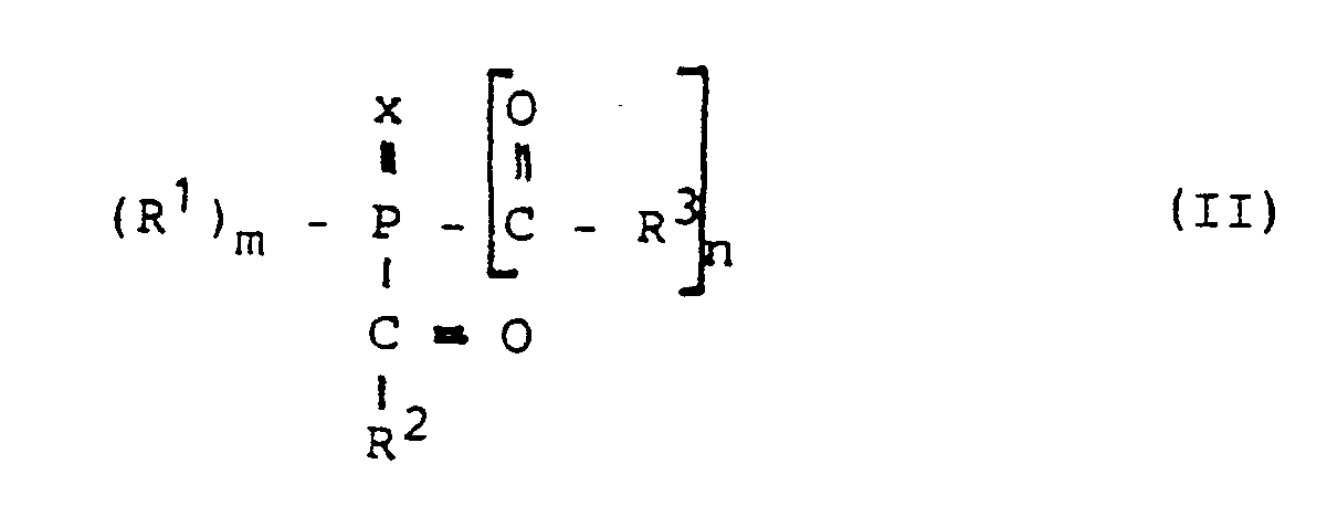
oder m = 2, n = 0 und x = 0 oder S,
R¹ einen geradkettigen oder verzweigten C₁₋₆-Alkylrest,
einen Cyclohexyl-, Cyclopentyl-, Phenyl-, Naphthyl- oder Biphenylylrest,
einen Cyclopentyl-, Cyclohexyl-, Phenyl-, Naphthyl- oder Biphenylylrest, der substituiert ist durch F, Cl, Br, J, C₁-C₄-Alkyl und/oder C₁-C₄-Alkoxyl,
einen S- oder N-haltigen 5- oder 6-gliedrigen heterocyclischen Ring,
R² und R³, die gleich oder verschieden sind,
einen Cyclohexyl-, Cyclopentyl-, Phenyl-, Naphthyl- oder Biphenylylrest,
einen Cyclopentyl-, Cyclohexyl-, Phenyl-, Naphthyl- oder Biphenylylrest, der substituiert ist durch F, Cl, Br, J, C₁-C₄-Alkyl und/oder C₁-C₄-Alkoxyl, oder
einen S- oder N-haltigen 5- oder 6-gliedrigen heterocyclischen Ring oder
R² und R³ miteinander zu einem Ring verknüpft sind, der 4 bis 10 Kohlenstoffatome enthält und durch 1 bis 6 C₁₋₄-Alkylreste substituiert sein kann.The diaryl iodonium salts are preferably used together with photoinitiators which generate free radicals under the action of light. Suitable photoinitiators of this type are mono- and α-diketones, benzoins, benzoin ethers, benzil ketals and in particular acylphosphine compounds of the general formula II:
or m = 2, n = 0 and x = 0 or S,
R¹ is a straight-chain or branched C₁₋₆ alkyl radical,
a cyclohexyl, cyclopentyl, phenyl, naphthyl or biphenylyl radical,
a cyclopentyl, cyclohexyl, phenyl, naphthyl or biphenylyl radical which is substituted by F, Cl, Br, J, C₁-C₄-alkyl and / or C₁-C₄-alkoxyl,
an S- or N-containing 5- or 6-membered heterocyclic ring,
R² and R³, which are the same or different,
a cyclohexyl, cyclopentyl, phenyl, naphthyl or biphenylyl radical,
a cyclopentyl, cyclohexyl, phenyl, naphthyl or biphenylyl radical which is substituted by F, Cl, Br, J, C₁-C₄-alkyl and / or C₁-C₄-alkoxyl, or
an S- or N-containing 5- or 6-membered heterocyclic ring or
R² and R³ are linked together to form a ring which contains 4 to 10 carbon atoms and can be substituted by 1 to 6 C₁₋₄-alkyl radicals.
Als Füllstoffe können in den erfindungsgemäß verwendeten Klebstoffmassen Pulver von Aluminiumoxid, Siliciumdioxid, Calciumcarbonat, Titandioxid, Bariumsulfat, Glimmer und dergleichen enthalten sein, während als thixotropierendes Mittel vorzugsweise pulverförmiges Siliciumdioxid mit einer spezifischen Oberfläche von 50 bis 450 m²/g enthalten sein kann. Die eingesetzten Füllstoffe sind vorzugsweise silanisiert. Als Silanisierungsmittel können die an sich bekannten Silan-Kupplungsmittel, beispielsweise γ-Methacryloyloxypropyltrimethoxysilan und Glycidyloxypropyltrimethoxysilan verwendet werden.Powders of aluminum oxide, silicon dioxide, calcium carbonate, titanium dioxide, barium sulfate, mica and the like can be contained as fillers in the adhesive compositions used according to the invention, while powdered silicon dioxide with a specific surface area of 50 to 450 m 2 / g can preferably be contained as a thixotropic agent. The fillers used are preferably silanized. The silane coupling agents known per se, for example γ-methacryloyloxypropyltrimethoxysilane and glycidyloxypropyltrimethoxysilane, can be used as silanizing agents.
Andere übliche Zusatzstoffe für die erfindungsgemäß verwendeten Klebstoffmassen sind beispielsweise Peroxide, Sensibilisatoren wie z.B. Anthracen, Pigmente, Farbstoffe, Antioxidantien und dergleichen.Other common additives for the adhesive compositions used according to the invention are for example peroxides, sensitizers such as e.g. Anthracene, pigments, dyes, antioxidants and the like.
Die Erfindung wird nachfolgend anhand der Zeichnung und der Ausführungsbeispiele weiter erläutert:The invention is further explained below with reference to the drawing and the exemplary embodiments:
Die Zeichnung zeigt schematisch den Ablauf einer der möglichen Ausführungsformen des erfindungsgemäßen Verfahrens zum Befestigen von SMD-Bauteilen auf einer Schaltungs- oder Leiterplatte. Das Verfahren besteht im wesentlichen aus der Folge der Verfahrensschritte A bis E:
- A -
Auftragen einer Klebstoffschicht 3 auf eine mit Kontaktanschlüssen 2 versehene Leiterplatte 1.Die photopolymerisierbare Klebstoffmasse 3 besitzt eine der vorstehend beschriebenen Zusammensetzungen und polymerisiert im wesentlichen nach einem kationischen Reaktionsmechanismus. DasAuftragen der Klebstoffschicht 3 kann durch Siebdruck, Pin-Transfer oder Dispenserauftrag in an sich bekannter Weise auf vorbestimmte Bereiche der Leiterplatte 1 erfolgen. Alternativ kann dieKlebstoffmasse 3 auch auf die Unterseite des auf der Leiterplatte 1 zu befestigenden Bauteils 4 aufgetragen werden. - B -
Aktivieren der Klebstoffschicht 3 durch Bestrahlen mit aktinischem Licht im ultravioletten oder sichtbaren Wellenlängenbereich zwischen 200 und 600 nm, vorzugsweise zwischen 400 und 500 nm, und zwar soweit und so lange, bis die gewünschte Initialklebrigkeit, jedoch keine Hautbildung an der Klebstoffoberfläche, eintritt. - C - Bestücken der Leiterplatte 1 durch Aufbringen des Bauteils 4 mit seinen Elektroden 5 auf die aktivierte Klebstoffschicht 3 und die Kontaktanschlüsse 2.
- D -
Aushärten der Klebstoffschicht 3 bei einer Temperatur zwischen 60 und 140°C, beispielsweise in einem Konvektionsofen, mittels Infrarotstrahler oder mittels der in Stufe B benutzten Quelle für aktinische Strahlung, falls diese auch Infrarotstrahlung emittiert. - E - Kontaktierung der (nicht dargestellten) Anschlüsse der Bauteile 4 mit den Leiterbahnen 2 durch Verlöten im Schwall- oder Schlepplötbad.
- A - Application of an
adhesive layer 3 to a printed circuit board 1 provided with contact connections 2. The photopolymerizableadhesive composition 3 has one of the compositions described above and polymerizes essentially according to a cationic reaction mechanism. Theadhesive layer 3 can be applied to predetermined areas of the printed circuit board 1 by screen printing, pin transfer or dispenser application in a manner known per se. Alternatively, theadhesive composition 3 can also be applied to the underside of the component 4 to be fastened on the printed circuit board 1. - B - Activate the
adhesive layer 3 by irradiating it with actinic light in the ultraviolet or visible wavelength range between 200 and 600 nm, preferably between 400 and 500 nm, to the extent and until the desired initial tack, but no skin formation on the adhesive surface, occurs. - C - equipping the printed circuit board 1 by applying the component 4 with its electrodes 5 to the activated
adhesive layer 3 and the contact connections 2. - D - curing the
adhesive layer 3 at a temperature between 60 and 140 ° C., for example in a convection oven, by means of infrared emitters or by means of the source for actinic radiation used in stage B, if this also emits infrared radiation. - E - Contacting the (not shown) connections of the components 4 to the conductor tracks 2 by soldering in the wave or soldering bath.
Bei einer anderen Ausführungsform des erfindungsgemäßen Verfahrens wird die Reihenfolge der Stufen A und B miteinander vertauscht, also die Aktivierung der Klebstoffmasse durch Bestrahlen mit aktinischem Licht bereits vorgenommen, bevor der Kleber entweder auf die Leiterplatte 1 oder die Unterseite des Bauteils 4 aufgetragen wird.In another embodiment of the method according to the invention, the sequence of stages A and B is interchanged, that is to say the activation of the adhesive composition by irradiation with actinic light is already carried out before the adhesive is applied either to the printed circuit board 1 or to the underside of the component 4.
Es wird eine Harzzusammensetzung durch gleichmäßiges Mischen von 100 Gew.-Teilen 3,4-Epoxycyclohexylmethyl-3′,4′-epoxycyclohexylcarboxylat, 3 Gew.-Teilen (η⁵-2,4-Cyclopentadien-1-yl)-[(1,2,3,4,5,6- )-(1-methylethyl)-benzol]-eisen(1+)-hexafluorophosphat(1-) (Irgacure® 261 der Fa. Ciba-Geigy) und 6 Gew.-Teilen pulverförmigen hydrophobierten Siliciumdioxids mit einer spezifischen Oberfläche von 71 m²/g und einer Teilchengröße kleiner 100 nm (Silica R-202 der Fa. Degussa) hergestellt.A resin composition is obtained by uniformly mixing 100 parts by weight of 3,4-epoxycyclohexylmethyl-3 ′, 4′-epoxycyclohexylcarboxylate, 3 parts by weight of (η⁵-2,4-cyclopentadien-1-yl) - [(1, 2,3,4,5,6-) - (1-methylethyl) -benzene] -iron (1 +) - hexafluorophosphate (1-) (Irgacure® 261 from Ciba-Geigy) and 6 parts by weight in powder form hydrophobized silicon dioxide with a specific surface area of 71 m 2 / g and a particle size smaller than 100 nm (Silica R-202 from Degussa).
Die Harzzusammensetzung weist eine Viskosität von 1,7 Pa.s auf (Haake-Viskosimeter Rotovisko RV 100, PKI 0.5/28, 10 %D). Die Harzzusammensetzung wird anschließend mittels eines Dispensers auf eine gedruckte Leiterplatte in Form eines standfesten Klebstofftropfens zwischen den Kontaktanschlüssen aufgebracht. Der Klebstofftropfen weist ein Verhältnis zwischen Durchmesser und Höhe von ca. 2:1 auf.The resin composition has a viscosity of 1.7 Pa.s (Haake viscometer Rotovisko RV 100, PKI 0.5 / 28, 10% D). The resin composition is then applied to a printed circuit board in the form of a stable drop of adhesive between the contact terminals by means of a dispenser. The drop of adhesive has a ratio between diameter and height of approx. 2: 1.
Der Klebstofftropfen wird anschließend mit einem Bestrahlungsgerät, welches aktinisches Licht im Bereich von 400 bis 500 nm aussendet (Curelight 01 der Fa. Precon, Lichtleistung ca. 100 mW/cm²), über einen Zeitraum von 20 sec. aktiviert. Danach wird ein Transistor im Gehäuse (Gehäuseform: SOT-23) darauf aufgebracht und mit einer Infrarotlampe (IR-Trocknungsaufsatz YTC01L der Fa. Sartorius, 250 W, Temperatur = 72°C) 1 Minute bestrahlt.The drop of adhesive is then activated over a period of 20 seconds with an irradiation device which emits actinic light in the range from 400 to 500 nm (Curelight 01 from Precon, light output approx. 100 mW / cm²). Then a transistor in the housing (housing shape: SOT-23) is applied to it and irradiated with an infrared lamp (IR drying attachment YTC01L from Sartorius, 250 W, temperature = 72 ° C) for 1 minute.
Anschließend wird die so bestückte Leiterplatte in ein Schlepplötbad (Fa. Zevatron Typ EFT-1) eingebracht. Die Leiterplatte wird mit maximaler Geschwindigkeitsstufe 10 in einen auf 250°C erhitzten Behälter mit geschmolzenem Lot eingefahren und 10 sec. eingetaucht belassen, um die zu verlötenden Elektrodenteile des SOT-Gehäuses mit den Verbindungsanschlüssen durch das Lötmittel zu verlöten. Während des Verlötens tritt keine Ablösung des SOT-Gehäuses von der gedruckten Leiterplatte auf, und man erhält ein einwandfrei verlötetes Bauteile.The printed circuit board equipped in this way is then placed in a drag soldering bath (Zevatron type EFT-1). The circuit board is moved at maximum speed level 10 into a container heated to 250 ° C. with molten solder and left immersed for 10 seconds in order to solder the electrode parts of the SOT housing to the connection connections using the solder. During the soldering, there is no detachment of the SOT housing from the printed circuit board, and a perfectly soldered component is obtained.
Das Eintauchen wird 5 x wiederholt, ohne daß eine Ablösung des SOT-Gehäuses von der gedruckten Leiterplatte eintritt.The immersion is repeated 5 times without the SOT housing detaching from the printed circuit board.
Die Harzzusammensetzung des Beispiels 1 wird mit zusätzlich 2 Gew.-Teilen silanisiertem Siliciumdioxid (R-202, Fa. Degussa) versetzt und zu einer homogenen Mischung verrührt.The resin composition of Example 1 is mixed with an additional 2 parts by weight of silanized silicon dioxide (R-202, from Degussa) and stirred into a homogeneous mixture.
Die Harzzusammensetzung weist eine Viskosität von 2,8 Pa.s (Haake-Viskosimeter Rotovisko RV 100, PKI 0.5/28, 10 %D) auf.The resin composition has a viscosity of 2.8 Pa.s (Haake viscometer Rotovisko RV 100, PKI 0.5 / 28, 10% D).
Mit dieser Harzzusammensetzung wird ein zylinderförmiger Widerstand (Melf) mit der Leiterplatte verklebt.With this resin composition, a cylindrical resistor (Melf) is glued to the circuit board.
Die Probe wird sofort nach dem Bestrahlen mit der Infrarotlampe (Bedingungen wie in Beispiel 1) auf einem Universalprüfgerät (Fa. Zwick 1435) vermessen. Die Festigkeit der Verbindung zwischen zylinderförmigem Bauteile und Leiterplatte wird durch Abscheren von der Leiterplatte (Vorschubgeschwindigkeit des Stempels 1 mm/Min.) ermittelt. Zum Abscheren des Bauteils ist eine Kraft von durchschnittlich 46 N erforderlich. Da die Fläche des Klebstofftropfens 4 mm² beträgt, kann eine durchschnittliche Scherfestigkeit von 11,5 N/mm² (MPa) ermittelt werden.The sample is measured immediately after irradiation with the infrared lamp (conditions as in Example 1) on a universal testing device (Zwick 1435). The strength of the connection between the cylindrical components and the printed circuit board is determined by shearing off the printed circuit board (feed speed of the stamp 1 mm / min.). An average force of 46 N is required to shear the component. Since the area of the adhesive drop is 4 mm², an average shear strength of 11.5 N / mm² (MPa) can be determined.
Ein gebräuchlicher warmhärtender Einkomponenten-Epoxid-Klebstoff für die Befestigung von SMD-Bauteilen auf Leiterplatten (Fa. Heraeus RD 860002 M) wird mittels eines Dispensers auf die gleiche gedruckte Leiterplatte wie im Beispiel 2 aufgetragen. Danach wird ein zylinderförmiger SMD-Widerstand (Melf) darauf aufgebracht und die Leiterplatte anschließend zur Härtung der Klebstoffschicht nach den Herstellungsangaben in einem Wärmeschrank belassen (Konvektionsofen 120°C, 3 Min.). Danach wird die bestückte Leiterplatte auf einer Universalprüfmaschine (Fa. Zwick 1435) vermessen. Das zylinderförmige SMD-Bauteil wird mittels eines Stempels mit einer Vorschubgeschwindigkeit von 1 mm/Min. abgeschert. Dazu ist eine Kraft von durchschnittlich 41 N erforderlich, woraus sich aus der Fläche des Klebstofftropfens von 5 mm² eine durchschnittliche Scherfestigkeit von 8,2 N/mm² (MPa) errechnet.A common thermosetting one-component epoxy adhesive for the attachment of SMD components to printed circuit boards (Heraeus RD 860002 M) is applied to the same printed circuit board as in Example 2 using a dispenser. A cylindrical SMD resistor (Melf) is then applied to it and the circuit board is then left in a heating cabinet to harden the adhesive layer according to the manufacturing instructions (convection oven 120 ° C., 3 minutes). Then the printed circuit board is measured on a universal testing machine (Zwick 1435). The cylindrical SMD component is stamped at a feed rate of 1 mm / min. sheared. This requires a force of 41 N on average, from which the area of the adhesive drop of 5 mm² is used to calculate an average shear strength of 8.2 N / mm² (MPa).
Im Vergleich zum erfindungsgemäßen Verfahren werden mit dem handelsüblichen Präparat trotz drastischer Aushärtebedingungen (3 Min. bei 120°C statt 1 Min. bei 72°C) schlechtere Abscherfestigkeiten erhalten.In comparison to the process according to the invention, the shear strengths obtained with the commercially available preparation are poorer in spite of drastic curing conditions (3 minutes at 120 ° C. instead of 1 minute at 72 ° C.).
Es wird eine Harzzusammensetzung durch gleichmäßiges Mischen von 80 Gew.-Teilen 3,4-Epoxycyclohexylmethyl-3′,4′-epoxycyclohexylcarboxylat, 20 Gew.-Teilen eines kationisch härtbaren Harzes (UVR 6351 der Fa. Union Carbide), 3 Gew.-Teilen Irgacure® 26i (der Fa. Ciba-Geigy) und 3 Gew.-Teilen hydrophobierten Siliciumdioxid-Pulvers einer mittleren Teilchengröße von kleiner 100 nm und einer spezifischen Oberfläche von 71 m²/g (Silica R-202 der Fa. Degussa) unter Rühren hergestellt.A resin composition is obtained by uniformly mixing 80 parts by weight of 3,4-epoxycyclohexylmethyl-3 ′, 4′-epoxycyclohexylcarboxylate, 20 parts by weight of a cationically curable resin (UVR 6351 from Union Carbide), 3 parts by weight. Parts of Irgacure® 26i (from Ciba-Geigy) and 3 parts by weight of hydrophobicized silicon dioxide powder with an average particle size of less than 100 nm and a specific surface area of 71 m² / g (Silica R-202 from Degussa) with stirring produced.
Die Viskosität beträgt 1,0 Pa.s (Haake-Viskosimeter Rotovisko RV 100, PKI 0.5/28, 10 %D).The viscosity is 1.0 Pa.s (Haake viscometer Rotovisko RV 100, PKI 0.5 / 28, 10% D).
Diese Harzzusammensetzung wird anschließend auf eine gedruckte Leiterplatte unter Verwendung eines Dispensers aufgebracht. Der Klebstofftropfen wird mit einer Ultraviolett-Strahlenquelle (UVAHAND 200 der Fa. Dr. Höhnle GmbH, emittiertes Licht von 315 bis 600 nm) im Abstand von 10 cm bestrahlt, was einer UVA-Bestrahlungsstärke von 15 mW/cm² entspricht. Die Bestrahlungszeit beträgt 30 sec. Danach wird ein Transistor im SOT-23-Gehäuse auf den aktivierten Klebstofftropfen aufgebracht und die gedruckte Leiterplatte mit einer Infrarotlampe (IR-Trocknungsaufsatz YTCO1L der Fa. Sartorius, 250 W) 2 Min. lang bestrahlt, wobei eine Temperatur von 80°C erreicht wird. Sofort nach der Bestrahlung wird die resultierende bestückte Leiterplatte in einem Schlepplötbad (Fa. Zevatron Typ EFT-1, maximale Geschwindigkeitsstufe 10) in einen auf 250°C erhitzten Behälter mit geschmolzenem Lot eingefahren und 10 sec. eingetaucht belassen. Es tritt keine Ablösung des Transistors im SOT-23-Gehäuse von der Leiterplatte auf, und man erhält ein einwandfrei verlötetes Bauteil.This resin composition is then applied to a printed circuit board using a dispenser. The drop of adhesive is irradiated with an ultraviolet radiation source (UVAHAND 200 from Dr. Höhnle GmbH, emitted light from 315 to 600 nm) at a distance of 10 cm, which corresponds to a UVA irradiance of 15 mW / cm². The irradiation time is 30 seconds. Then a transistor in the SOT-23 housing is applied to the activated adhesive drop and the printed circuit board is irradiated for 2 minutes with an infrared lamp (IR drying attachment YTCO1L from Sartorius, 250 W), at a temperature of 80 ° C is reached. Immediately after the irradiation, the resulting populated printed circuit board is moved in a drag soldering bath (Zevatron type EFT-1, maximum speed level 10) into a container heated to 250 ° C. with molten solder and left immersed for 10 seconds. There is no detachment of the transistor in the SOT-23 housing from the printed circuit board, and a perfectly soldered component is obtained.
Es wird eine Harzzusammensetzung durch gleichmäßiges Mischen von 100 Gew.-Teilen eines Bisphenol-A-Diepoxids (GY 259 der Fa. Ciba-Geigy), 3 Gew.-Teilen Irgacure® 261 (der Fa. Ciba-Geigy) und 2,5 Gew.-Teilen Cumolhydroperoxid hergestellt.A resin composition is obtained by uniformly mixing 100 parts by weight of a bisphenol A diepoxide (GY 259 from Ciba-Geigy), 3 parts by weight of Irgacure® 261 (from Ciba-Geigy) and 2.5 Parts by weight of cumene hydroperoxide.
Die Harzzusammensetzung weist eine Viskosität von 11 Pa.s auf (Haake Viskosimeter Rotovisko RV 100, PKI 0.5/28, 10 %D). Mit dieser Harzzusammensetzung wird die gleiche Probe wie in Beispiel 1 hergestellt, mit der einzigen Ausnahme, daß anstelle des SOT-Gehäuses ein quaderförmiger Elektrolytkondensator (15 D der Fa. Philips) verklebt wird. Die Probe wird sofort nach dem Bestrahlen mit der Infrarotlampe (unter Bedingungen wie in Beispiel 1 genannt) in ein Schlepplötbad (Fa. Zevatron Typ EFT-1) eingebracht. Die Leiterplatte wird mit Geschwindigkeitsstufe 4 in einen auf 250°C erhitzten Behälter mit geschmolzenem Lot eingefahren und 5 sec. eingetaucht belassen. Während des Verlötens tritt keine Ablösung des Elco-Gehäuses von der gedruckten Leiterplatte auf. Die Verlötung ist einwandfrei.The resin composition has a viscosity of 11 Pa.s (Haake viscometer Rotovisko RV 100, PKI 0.5 / 28, 10% D). The same sample as in Example 1 is produced with this resin composition, with the only exception that instead of the SOT housing, a cuboidal electrolytic capacitor (15 D from Philips) is bonded. The sample is immediately after irradiation with the infrared lamp (under Conditions as mentioned in Example 1) in a drag soldering bath (from Zevatron type EFT-1). The circuit board is moved at speed level 4 into a container heated to 250 ° C. with molten solder and left immersed for 5 seconds. There is no detachment of the Elco housing from the printed circuit board during soldering. The soldering is flawless.
Es wird eine Harzzusammensetzung durch gleichmäßiges Mischen von 50 Gew.-Teilen 3,4-Epoxycyclohexylmethyl-3′,4′epoxycyclohexylcarboxylat, 50 Gew.-Teilen Triethylenglykoldivinylether, 4 Gew.-Teilen Ethylenglykol, 3 Gew.-Teilen Bis-(4-methylphenyl)-jodoniumhexafluorophosphat, 1 Gew.-Teil Bis-(2,6-dichlorbenzoyl)-4-n-propylphenylphosphinoxid und 3 Gew.-Teilen pulverförmigen hydrophobierten Siliciumdioxids mit einer spezifischen Oberfläche von 71 m²/g und einer Teilchengröße von kleiner 100 nm (Silica R-202 der Fa. Degussa) hergestellt.A resin composition is obtained by uniformly mixing 50 parts by weight of 3,4-epoxycyclohexylmethyl-3 ′, 4′epoxycyclohexylcarboxylate, 50 parts by weight of triethylene glycol divinyl ether, 4 parts by weight of ethylene glycol, 3 parts by weight of bis- (4- methylphenyl) iodonium hexafluorophosphate, 1 part by weight of bis- (2,6-dichlorobenzoyl) -4-n-propylphenylphosphine oxide and 3 parts by weight of powdered hydrophobic silicon dioxide with a specific surface area of 71 m² / g and a particle size of less than 100 nm (Silica R-202 from Degussa).
Die Harzzusammensetzung weist eine Viskosität von 0,05 Pa.s auf (Haake-Viskosimeter Rotovisko RV 100, PKI 0.5/28, 10 %D). Die Harzzusammensetzung wird anschließend mit Hilfe eines Dispensers auf eine gedruckte Leiterplatte in Form eines Klebstofftropfens zwischen den Kontaktanschlüssen aufgebracht.The resin composition has a viscosity of 0.05 Pa.s (Haake viscometer Rotovisko RV 100, PKI 0.5 / 28, 10% D). The resin composition is then applied to a printed circuit board in the form of a drop of adhesive between the contact terminals with the aid of a dispenser.
Der Klebstofftropfen wird anschließend mit einem Bestrahlungsgerät, welches aktinisches Licht im Bereich von 400 bis 500 nm aussendet (Curelight 01 der Fa. Precon, ca. 100 mW/cm²), 20 sec. lang aktiviert. Danach wird die Leiterplatte von Hand mit einem Elektrolytkondensator (15 D der Fa. Philips) bestückt und mit einer Infrarotlampe (Infrarot-Trocknungsaufsatz der Fa. Sartorius, 250 W, Temperatur = 72°C) 1 Min. bestrahlt.The drop of adhesive is then activated for 20 seconds using an irradiation device which emits actinic light in the range from 400 to 500 nm (Curelight 01 from Precon, approx. 100 mW / cm²). The circuit board is then manually fitted with an electrolytic capacitor (15 D from Philips) and irradiated with an infrared lamp (infrared drying attachment from Sartorius, 250 W, temperature = 72 ° C) for 1 minute.
Danach wird die resultierende bestückte Leiterplatte in ein Schlepplötbad (Fa. Zevatron Typ EFT-1) eingebracht. Die Leiterplatte wird mit Geschwindigkeitsstufe 4 in einen auf 250°C erhitzten Behälter mit geschmolzenem Lot eingefahren und 3 sec. eingetaucht belassen. Während des Verlötens tritt keine Ablösung des Elco-Gehäuses von der gedruckten Leiterplatte auf. Die Verlötung ist völlig in Ordnung.The resulting printed circuit board is then placed in a drag soldering bath (Zevatron type EFT-1). The circuit board is moved at speed level 4 into a container of molten solder heated to 250 ° C. and left immersed for 3 seconds. There is no detachment of the Elco housing from the printed circuit board during soldering. The soldering is perfectly fine.
Das Eintauchen wird sofort wiederholt, ohne daß daraufhin eine Ablösung des Elco-Gehäuses von der gedruckten Leiterplatte eintritt.The immersion is repeated immediately without the Elco housing becoming detached from the printed circuit board.
Ein gebräuchlicher Einkomponenten-Epoxid-Klebstoff (RD860002M der Fa. Heraeus) für die Befestigung von SMD-Bauteilen auf Leiterplatten wird mittels eines Dispensers auf die gleiche gedruckte Leiterplatte wie im Beispiel 5 aufgetragen. Danach wird ein quaderförmiger SMD-Bauteil (Elektrolytkondensator 15 D der Fa. Philips) darauf aufgebracht und die Leiterplatte anschließend zur Härtung der Klebstoffschicht mit einer Infrarotlampe (Trocknungsaufsatz der Fa. Sartorius, 250 W, Temperatur = 72°C) 3 Min. bestrahlt.A common one-component epoxy adhesive (RD860002M from Heraeus) for fastening SMD components to printed circuit boards is applied to the same printed circuit board as in Example 5 using a dispenser. Then a cuboid SMD component (electrolytic capacitor 15 D from Philips) is applied to it and the circuit board is then irradiated with an infrared lamp (drying attachment from Sartorius, 250 W, temperature = 72 ° C) for 3 minutes to harden the adhesive layer.
Danach wird die resultierende bestückte Leiterplatte in ein Schlepplötbad (Fa. Zevatron Typ EFT-1) eingebracht. Die Leiterplatte wird mit Geschwindigkeitsstufe 4 in einen auf 250°C erhitzten Behälter mit geschmolzenem Lot eingefahren und 3 sec. eingetaucht belassen. Dabei löst sich der SMD-Bauteil von der gedruckten Leiterplatte ab. Der gebräuchliche Einkomponenten-Epoxid-Klebstoff ist unter diesen milden Aushärtungsbedingungen (1 Min. thermische Aushärtung bei 72°C) zur Verklebung von SMD-Bauteilen nicht geeignet.The resulting printed circuit board is then placed in a drag soldering bath (Zevatron type EFT-1). The circuit board is moved at speed level 4 into a container of molten solder heated to 250 ° C. and left immersed for 3 seconds. The SMD component detaches from the printed circuit board. The common one-component epoxy adhesive is not suitable under these mild curing conditions (1 minute thermal curing at 72 ° C) for bonding SMD components.
Ein gebräuchlicher Einkomponenten-Epoxid-Klebstoff für die Befestigung von SMD-Bauteilen auf Leiterplatten (Amicon D-124-F der Fa. Emerson and Cuming) wird wie im Vergleichsbeispiel 2 beschrieben auf eine gedruckte Leiterplatte aufgebracht und unter denselben Bedingungen ausgehärtet und im Schlepplötbad geprüft.A common one-component epoxy adhesive for attaching SMD components to printed circuit boards (Amicon D-124-F from Emerson and Cuming) is applied to a printed circuit board as described in Comparative Example 2 and cured under the same conditions and tested in a soldering bath .
Während des Verlötens löst sich der SMD-Bauteil von der gedruckten Leiterplatte ab. Dieser gebräuchliche Einkomponenten-Epoxid-Klebstoff ist unter diesen milden Aushärtungsbedingungen als SMD-Klebstoff nicht geeignet.During the soldering process, the SMD component detaches from the printed circuit board. This common one-component epoxy adhesive is not suitable as an SMD adhesive under these mild curing conditions.
Es wird eine Harzzusammensetzung durch gleichmäßiges Mischen von 100 Gew.-Teilen 3,4-Epoxycyclohexylmethyl-3′,4′-epoxycyclohexylcarboxylat, 2,5 Gew.-Teilen Cumolhydroperoxid, 3 Gew.-Teilen Irgacure® 261 (der Fa. Ciba-Geigy) und 3 Gew.-Teilen hydrophobierten Siliciumdioxid-Pulvers mit einer spezifischen Oberfläche von 71 m²/g und mittleren Teilchengröße von kleiner 100 nm (R-202 der Fa. Degussa) unter Rühren hergestellt.A resin composition is obtained by uniformly mixing 100 parts by weight of 3,4-epoxycyclohexylmethyl-3 ′, 4′-epoxycyclohexylcarboxylate, 2.5 parts by weight of cumene hydroperoxide, 3 parts by weight of Irgacure® 261 (from Ciba- Geigy) and 3 parts by weight of hydrophobized silicon dioxide powder with a specific surface area of 71 m 2 / g and average particle size of less than 100 nm (R-202 from Degussa) with stirring.
Die Harzzusammensetung weist eine Viskosität von 0,95 Pa.s auf (Haake-Viskosimeter Rotovisko RV 100, PKI 0.5/28, 10 %D).The resin composition has a viscosity of 0.95 Pa.s (Haake viscometer Rotovisko RV 100, PKI 0.5 / 28, 10% D).
Aus dieser Harzzusammensetzung werden anschließend mittels eines Stiftes (pin transfer) zwei Klebstofftropfen auf einen SMD-Bauteil (IC D7508G der Fa. NEC) aufgebracht.From this resin composition, two drops of adhesive are then applied to an SMD component (IC D7508G from NEC) using a pin (pin transfer).
Die Klebstofftropfen werden anschließend mit einem Bestrahlungsgerät, welches aktinisches Licht im Bereich von 400 bis 500 nm aussendet (Curelight 01 der Fa. Precon, ca. 100 mW/cm²), 15 sec. aktiviert. Danach wird eine gedruckte Leiterplatte mit diesem SMD-Bauteil bestückt und mit einer Infrarotlampe (IR-Trocknungsaufsatz YTC01L der Fa. Sartorius, 250 W) 2 Min. bestrahlt (Temperatur = 72°C).The adhesive drops are then activated with an irradiation device which emits actinic light in the range from 400 to 500 nm (Curelight 01 from Precon, approx. 100 mW / cm²) for 15 seconds. Then a printed circuit board is equipped with this SMD component and with one Infrared lamp (IR drying attachment YTC01L from Sartorius, 250 W) irradiated for 2 minutes (temperature = 72 ° C).
Danach wird die resultierende bestückte Leiterplatte in ein Schlepplötbad (Fa. Zevatron Typ EFT-1) eingebracht. Die Leiterplatte wird mit maximaler Geschwindigkeitsstufe 10 in einen auf 250°C erhitzten Behälter mit geschmolzenem Lot eingefahren und 3 sec. eingetaucht belassen. Während des Verlötens tritt keine Ablösung des SMD-Bauteils von der gedruckten Leiterplatte auf. Die Verlötung ist einwandfrei.The resulting printed circuit board is then placed in a drag soldering bath (Zevatron type EFT-1). The circuit board is moved at maximum speed level 10 into a container heated to 250 ° C. with molten solder and left immersed for 3 seconds. There is no detachment of the SMD component from the printed circuit board during the soldering. The soldering is flawless.
Das Eintauchen wird 3 x wiederholt. Hierbei tritt keine Ablösung des SMD-Bauteils von der gedruckten Leiterplatte auf.The immersion is repeated 3 times. There is no detachment of the SMD component from the printed circuit board.
Ein gebräuchlicher Einkomponenten-Epoxid-Klebstoff für die Befestigung von SMD-Bauteilen auf Leiterplatten (Amicon D124-F der Fa. Emerson and Cuming) wird wie in Beispiel 6 mittels eines Stiftes auf ein SMD-Bauteil (D7508G der Fa. NEC) aufgetragen und danach 5 Min. mit derselben Infrarotlampe wie in Beispiel 6 bestrahlt.A common one-component epoxy adhesive for attaching SMD components to printed circuit boards (Amicon D124-F from Emerson and Cuming) is applied to an SMD component (D7508G from NEC) using a pen, as in Example 6, and then irradiated for 5 minutes with the same infrared lamp as in Example 6.
Danach wird die resultierende bestückte Leiterplatte unter denselben Bedingungen wie in Beispiel 6 in den Behälter mit geschmolzenem Lot eingefahren. Dabei löst sich das SMD-Bauteil von der Leiterplatte.The resulting populated circuit board is then inserted into the molten solder container under the same conditions as in Example 6. The SMD component detaches from the circuit board.
Dieser gebräuchliche Einkomponenten-Epoxid-Klebstoff ist unter diesen milden Aushärtungsbedingungen (5 Min. thermische Aushärtung bei 72°C) für die Verklebung von SMD-Teilen nicht geeignet.This common one-component epoxy adhesive is not suitable under these mild curing conditions (5 minutes of thermal curing at 72 ° C) for the bonding of SMD parts.
Claims (10)
Applications Claiming Priority (2)
| Application Number | Priority Date | Filing Date | Title |
|---|---|---|---|
| DE3806738A DE3806738C1 (en) | 1988-03-02 | 1988-03-02 | |
| DE3806738 | 1988-03-02 |
Publications (3)
| Publication Number | Publication Date |
|---|---|
| EP0330909A2 true EP0330909A2 (en) | 1989-09-06 |
| EP0330909A3 EP0330909A3 (en) | 1991-05-29 |
| EP0330909B1 EP0330909B1 (en) | 1994-12-28 |
Family
ID=6348626
Family Applications (1)
| Application Number | Title | Priority Date | Filing Date |
|---|---|---|---|
| EP89102571A Expired - Lifetime EP0330909B1 (en) | 1988-03-02 | 1989-02-15 | Process for mounting parts on a printed-circuit board |
Country Status (5)
| Country | Link |
|---|---|
| US (1) | US4916805A (en) |
| EP (1) | EP0330909B1 (en) |
| JP (1) | JPH0214596A (en) |
| AT (1) | ATE116512T1 (en) |
| DE (2) | DE3806738C1 (en) |
Cited By (2)
| Publication number | Priority date | Publication date | Assignee | Title |
|---|---|---|---|---|
| WO1995009521A1 (en) * | 1993-09-22 | 1995-04-06 | Samsung Electronics Co., Ltd. | Local hardening method of a semiconductor integrated circuit |
| EP0691679A3 (en) * | 1994-06-07 | 1996-05-01 | Texas Instruments Inc | Process for manufacturing an integrated circuit package assembly |
Families Citing this family (31)
| Publication number | Priority date | Publication date | Assignee | Title |
|---|---|---|---|---|
| DE3909688A1 (en) * | 1989-03-23 | 1990-09-27 | Espe Stiftung | METHOD FOR GLUING OR POOLING SUBSTRATES AND DEVICE FOR CARRYING OUT ITSELF |
| US5487853A (en) * | 1990-07-12 | 1996-01-30 | The C. A. Lawton Company | Energetic stitching for complex preforms |
| US5066368A (en) * | 1990-08-17 | 1991-11-19 | Olin Corporation | Process for producing black integrally colored anodized aluminum components |
| US5177134A (en) * | 1990-12-03 | 1993-01-05 | Motorola, Inc. | Tacking agent |
| US5318651A (en) * | 1991-11-27 | 1994-06-07 | Nec Corporation | Method of bonding circuit boards |
| US5698059A (en) * | 1992-11-10 | 1997-12-16 | Alliedsignal Inc. | Filter and method for manufacturing filters |
| DE4447701C2 (en) * | 1994-09-20 | 1997-06-26 | Blaupunkt Werke Gmbh | Automatic mounting of electronic SMD components on both sides of circuit board |
| JP4094080B2 (en) * | 1995-11-22 | 2008-06-04 | リンテック株式会社 | Adhesive composition and adhesive sheet |
| DE19641863C1 (en) * | 1996-10-10 | 1998-03-12 | Erwin Hagn | Electrical component suction surface formation method e.g. for SMD components on PCB |
| DE29617668U1 (en) * | 1996-10-10 | 1996-12-05 | Hagn Erwin | Device for producing a suction surface on an object and electrical component formed thereby |
| EP0950082B1 (en) * | 1997-01-06 | 2003-04-23 | Quantum Materials, Inc. | Reducing void formation in curable adhesive formulations |
| US6309502B1 (en) * | 1997-08-19 | 2001-10-30 | 3M Innovative Properties Company | Conductive epoxy resin compositions, anisotropically conductive adhesive films and electrical connecting methods |
| JP3714088B2 (en) * | 1999-02-18 | 2005-11-09 | 株式会社村田製作所 | Electronic component and manufacturing method thereof |
| US6245827B1 (en) * | 1999-10-12 | 2001-06-12 | Elementis Specialties, Inc. | Ultraviolet curable resin compositions having enhanced shadow cure properties |
| DE19961347A1 (en) | 1999-12-17 | 2001-06-21 | S & C Polymer Silicon & Compos | Photoinitiator system with acylphosphine oxide initiators |
| JP2001237585A (en) * | 2000-02-22 | 2001-08-31 | Murata Mfg Co Ltd | Electronic component and manufacturing method thereof |
| JP2002076589A (en) | 2000-08-31 | 2002-03-15 | Hitachi Ltd | Electronic device and its manufacturing method |
| US6767607B2 (en) * | 2001-08-09 | 2004-07-27 | Corning Incorporated | Multiwell plate having transparent well bottoms |
| US6918984B2 (en) * | 2002-06-24 | 2005-07-19 | Loctite (R&D) Limited | Photocurable adhesive compositions, reaction products of which have low halide ion content |
| TWM252154U (en) * | 2003-10-24 | 2004-12-01 | Hon Hai Prec Ind Co Ltd | Electrical connector having pick up cap |
| US8030401B1 (en) | 2006-08-03 | 2011-10-04 | Henkel Corporation | Photoinitiated cationic epoxy compositions |
| DE102006048464A1 (en) * | 2006-10-11 | 2008-04-17 | Bundesdruckerei Gmbh | Adhesive layer for the connection of a holographic data carrier with a substrate |
| US7714037B1 (en) | 2006-12-15 | 2010-05-11 | Henkel Corporation | Photoinitiated cationic epoxy compositions and articles exhibiting low color |
| US8309633B2 (en) * | 2008-07-17 | 2012-11-13 | Henkel Ireland Ltd. | Low temperature, cationically curable compositions with improved cure speed and toughness |
| US9162249B2 (en) * | 2008-10-01 | 2015-10-20 | Panasonic Intellectual Property Management Co., Ltd. | Paste dispenser for applying paste containing fillers using nozzle with pin and application method using the same |
| JP4760899B2 (en) * | 2008-12-12 | 2011-08-31 | 株式会社村田製作所 | Manufacturing method of chip-shaped electronic component |
| AT513747B1 (en) | 2013-02-28 | 2014-07-15 | Mikroelektronik Ges Mit Beschränkter Haftung Ab | Assembly process for circuit carriers and circuit carriers |
| WO2018150573A1 (en) * | 2017-02-20 | 2018-08-23 | 株式会社Fuji | Component mounting system and component mounting method |
| JP6937466B2 (en) | 2018-02-26 | 2021-09-22 | パナソニックIpマネジメント株式会社 | Coating method and coating equipment and parts manufacturing method |
| CN108896545B (en) * | 2018-05-09 | 2021-07-13 | 歌尔光学科技有限公司 | Gluing detection method and device and computer readable storage medium |
| FR3110382B1 (en) * | 2020-05-20 | 2022-05-13 | Pkvitality | Sensor for surface mounted body monitoring system |
Citations (6)
| Publication number | Priority date | Publication date | Assignee | Title |
|---|---|---|---|---|
| GB2014791A (en) * | 1978-02-08 | 1979-08-30 | Hitachi Ltd | Method for mounting parts on circuit boards |
| GB2065124A (en) * | 1979-12-11 | 1981-06-24 | Gen Electric | Method of adhesive bonding using visible light cured epoxy resins |
| GB2119810A (en) * | 1982-04-26 | 1983-11-23 | Grace W R & Co | UV and thermally curable, thermoplastic-containing compositions |
| WO1985001634A1 (en) * | 1983-09-27 | 1985-04-11 | Dortrell Limited | Electronic circuit assembly |
| EP0154819A1 (en) * | 1984-01-07 | 1985-09-18 | Takeda Chemical Industries, Ltd. | Method of adhesion and composition therefor |
| EP0182744A2 (en) * | 1984-11-14 | 1986-05-28 | Ciba-Geigy Ag | Radiation curable filled epoxy resin compositions and their use |
Family Cites Families (9)
| Publication number | Priority date | Publication date | Assignee | Title |
|---|---|---|---|---|
| DE2119436B2 (en) * | 1971-04-21 | 1973-11-15 | Siemens Ag, 1000 Berlin U. 8000 Muenchen | Process for combining thin and thick film circuits |
| JPS55110097A (en) * | 1979-02-19 | 1980-08-25 | Matsushita Electric Ind Co Ltd | Method of mounting electronic part |
| DE2908485A1 (en) * | 1979-03-05 | 1980-09-11 | Licentia Gmbh | METHOD FOR EMBEDDING SEMICONDUCTOR COMPONENTS IN PLASTIC |
| JPS55127098A (en) * | 1979-03-09 | 1980-10-01 | Matsushita Electric Ind Co Ltd | Method of mounting electronic part |
| US4398660A (en) * | 1981-06-04 | 1983-08-16 | Rca Corporation | Method of mounting electronic components |
| US4605465A (en) * | 1982-04-26 | 1986-08-12 | W. R. Grace & Co. | UV and thermally curable, thermoplastic-containing compositions |
| US4427478A (en) * | 1982-06-28 | 1984-01-24 | International Business Machines Corporation | Process for making an encapsulated circuit board and products made thereby |
| JPS6352341B2 (en) * | 1982-07-13 | 1988-10-18 | Smithkline Beckman Corp | |
| US4778556A (en) * | 1986-04-21 | 1988-10-18 | Unisys Corporation | Apparatus for correcting printed circuit boards |
-
1988
- 1988-03-02 DE DE3806738A patent/DE3806738C1/de not_active Expired
-
1989
- 1989-02-15 DE DE58908810T patent/DE58908810D1/en not_active Expired - Fee Related
- 1989-02-15 EP EP89102571A patent/EP0330909B1/en not_active Expired - Lifetime
- 1989-02-15 AT AT89102571T patent/ATE116512T1/en not_active IP Right Cessation
- 1989-03-01 US US07/317,671 patent/US4916805A/en not_active Expired - Fee Related
- 1989-03-02 JP JP1050973A patent/JPH0214596A/en active Pending
Patent Citations (6)
| Publication number | Priority date | Publication date | Assignee | Title |
|---|---|---|---|---|
| GB2014791A (en) * | 1978-02-08 | 1979-08-30 | Hitachi Ltd | Method for mounting parts on circuit boards |
| GB2065124A (en) * | 1979-12-11 | 1981-06-24 | Gen Electric | Method of adhesive bonding using visible light cured epoxy resins |
| GB2119810A (en) * | 1982-04-26 | 1983-11-23 | Grace W R & Co | UV and thermally curable, thermoplastic-containing compositions |
| WO1985001634A1 (en) * | 1983-09-27 | 1985-04-11 | Dortrell Limited | Electronic circuit assembly |
| EP0154819A1 (en) * | 1984-01-07 | 1985-09-18 | Takeda Chemical Industries, Ltd. | Method of adhesion and composition therefor |
| EP0182744A2 (en) * | 1984-11-14 | 1986-05-28 | Ciba-Geigy Ag | Radiation curable filled epoxy resin compositions and their use |
Cited By (3)
| Publication number | Priority date | Publication date | Assignee | Title |
|---|---|---|---|---|
| WO1995009521A1 (en) * | 1993-09-22 | 1995-04-06 | Samsung Electronics Co., Ltd. | Local hardening method of a semiconductor integrated circuit |
| EP0691679A3 (en) * | 1994-06-07 | 1996-05-01 | Texas Instruments Inc | Process for manufacturing an integrated circuit package assembly |
| US5846476A (en) * | 1994-06-07 | 1998-12-08 | Texas Instruments Incorporated | Optical curing process for intergrated circuit package assembly |
Also Published As
| Publication number | Publication date |
|---|---|
| EP0330909B1 (en) | 1994-12-28 |
| DE3806738C1 (en) | 1989-09-07 |
| JPH0214596A (en) | 1990-01-18 |
| DE58908810D1 (en) | 1995-02-09 |
| EP0330909A3 (en) | 1991-05-29 |
| US4916805A (en) | 1990-04-17 |
| ATE116512T1 (en) | 1995-01-15 |
Similar Documents
| Publication | Publication Date | Title |
|---|---|---|
| EP0330909B1 (en) | Process for mounting parts on a printed-circuit board | |
| DE2904649C2 (en) | Adhesive composition and method of securing electronic components to printed circuit boards | |
| DE2518652C2 (en) | Curable compositions | |
| DE69935810T2 (en) | METHOD FOR PRODUCING A LAMINATED STRUCTURE | |
| EP0504569A2 (en) | Method of coating or sealing of electronic components or component groups | |
| DE2618897A1 (en) | HARDABLE COMPOSITIONS | |
| EP0388775B1 (en) | Method and apparatus for glueing or moulding of substrates | |
| EP0146501A2 (en) | Polymerizable compositions | |
| DE102017001696A1 (en) | UV-activated structural pressure-sensitive adhesive tape | |
| EP0661324B1 (en) | Hight-initiated cationic curable epoxyresin compositions and their use | |
| DE19705027C2 (en) | Method for gluing a component to a surface | |
| DE60103634T2 (en) | ANISOTROPICALLY CONDUCTIVE ADHESIVE COMPOSITION AND ANISOTROPICALLY CONDUCTIVE ADHESIVE FILM PRODUCED THEREFROM | |
| WO1994010223A1 (en) | Unitary reaction resin systems | |
| EP0386473B1 (en) | Drop-covering mass for electric and electronic devices | |
| EP0688804A2 (en) | Cationically hardening multicomponent epoxy resin compositions and a process for their cure | |
| DE2232822C2 (en) | Photohardenable mass | |
| DE4324322A1 (en) | Flexibilised epoxy resin compositions which cure with photoinitiation, their preparation and use | |
| EP0584570B1 (en) | Epoxy resin composition containing sulphonium salts | |
| WO1997021229A2 (en) | Electrically conducting reaction resin mixture | |
| DE4038989A1 (en) | Tension-free bonding of flat workpiece to substrate - with different coefft. of thermal expansion using cationically hardening resin compsn. which is irradiated then heated to moderate temp. | |
| DE19538468B4 (en) | Method for the surface bonding of workpieces, glued composite and use thereof | |
| DE10127704A1 (en) | Resin formulation, process for its hardening and its use | |
| DE2356856C3 (en) | Epoxy resin preparation and a method for protecting electronic components using the preparation | |
| WO2002046263A1 (en) | Resin formulation, method for curing the same, and its use | |
| WO1997042638A1 (en) | Electroconductive gluing process |
Legal Events
| Date | Code | Title | Description |
|---|---|---|---|
| PUAI | Public reference made under article 153(3) epc to a published international application that has entered the european phase |
Free format text: ORIGINAL CODE: 0009012 |
|
| AK | Designated contracting states |
Kind code of ref document: A2 Designated state(s): AT BE CH DE ES FR GB IT LI NL SE |
|
| 17P | Request for examination filed |
Effective date: 19901204 |
|
| PUAL | Search report despatched |
Free format text: ORIGINAL CODE: 0009013 |
|
| AK | Designated contracting states |
Kind code of ref document: A3 Designated state(s): AT BE CH DE ES FR GB IT LI NL SE |
|
| RAP1 | Party data changed (applicant data changed or rights of an application transferred) |
Owner name: THERA PATENT GMBH & CO. KG GESELLSCHAFT FUER INDUS |
|
| 17Q | First examination report despatched |
Effective date: 19930603 |
|
| GRAA | (expected) grant |
Free format text: ORIGINAL CODE: 0009210 |
|
| PGFP | Annual fee paid to national office [announced via postgrant information from national office to epo] |
Ref country code: AT Payment date: 19941222 Year of fee payment: 7 |
|
| AK | Designated contracting states |
Kind code of ref document: B1 Designated state(s): AT BE CH DE ES FR GB IT LI NL SE |
|
| PG25 | Lapsed in a contracting state [announced via postgrant information from national office to epo] |
Ref country code: IT Free format text: LAPSE BECAUSE OF FAILURE TO SUBMIT A TRANSLATION OF THE DESCRIPTION OR TO PAY THE FEE WITHIN THE PRE;WARNING: LAPSES OF ITALIAN PATENTS WITH EFFECTIVE DATE BEFORE 2007 MAY HAVE OCCURRED AT ANY TIME BEFORE 2007. THE CORRECT EFFECTIVE DATE MAY BE DIFFERENT FROM THE ONE RECORDED.SCRIBED TIME-LIMIT Effective date: 19941228 Ref country code: ES Free format text: THE PATENT HAS BEEN ANNULLED BY A DECISION OF A NATIONAL AUTHORITY Effective date: 19941228 Ref country code: BE Effective date: 19941228 Ref country code: FR Effective date: 19941228 Ref country code: NL Effective date: 19941228 Ref country code: GB Effective date: 19941228 |
|
| REF | Corresponds to: |
Ref document number: 116512 Country of ref document: AT Date of ref document: 19950115 Kind code of ref document: T |
|
| REF | Corresponds to: |
Ref document number: 58908810 Country of ref document: DE Date of ref document: 19950209 |
|
| PG25 | Lapsed in a contracting state [announced via postgrant information from national office to epo] |
Ref country code: SE Effective date: 19950328 |
|
| PGFP | Annual fee paid to national office [announced via postgrant information from national office to epo] |
Ref country code: CH Payment date: 19950428 Year of fee payment: 7 |
|
| EN | Fr: translation not filed | ||
| NLV1 | Nl: lapsed or annulled due to failure to fulfill the requirements of art. 29p and 29m of the patents act | ||
| GBV | Gb: ep patent (uk) treated as always having been void in accordance with gb section 77(7)/1977 [no translation filed] |
Effective date: 19941228 |
|
| PLBE | No opposition filed within time limit |
Free format text: ORIGINAL CODE: 0009261 |
|
| STAA | Information on the status of an ep patent application or granted ep patent |
Free format text: STATUS: NO OPPOSITION FILED WITHIN TIME LIMIT |
|
| 26N | No opposition filed | ||
| PG25 | Lapsed in a contracting state [announced via postgrant information from national office to epo] |
Ref country code: AT Effective date: 19960215 |
|
| PG25 | Lapsed in a contracting state [announced via postgrant information from national office to epo] |
Ref country code: CH Free format text: LAPSE BECAUSE OF NON-PAYMENT OF DUE FEES Effective date: 19960228 Ref country code: LI Free format text: LAPSE BECAUSE OF NON-PAYMENT OF DUE FEES Effective date: 19960228 |
|
| REG | Reference to a national code |
Ref country code: CH Ref legal event code: PL |
|
| PGFP | Annual fee paid to national office [announced via postgrant information from national office to epo] |
Ref country code: DE Payment date: 19970314 Year of fee payment: 9 |
|
| PG25 | Lapsed in a contracting state [announced via postgrant information from national office to epo] |
Ref country code: DE Free format text: LAPSE BECAUSE OF NON-PAYMENT OF DUE FEES Effective date: 19981103 |