EP0330422B1 - Control system for a continuously variable transmission - Google Patents
Control system for a continuously variable transmission Download PDFInfo
- Publication number
- EP0330422B1 EP0330422B1 EP89301661A EP89301661A EP0330422B1 EP 0330422 B1 EP0330422 B1 EP 0330422B1 EP 89301661 A EP89301661 A EP 89301661A EP 89301661 A EP89301661 A EP 89301661A EP 0330422 B1 EP0330422 B1 EP 0330422B1
- Authority
- EP
- European Patent Office
- Prior art keywords
- signal
- transmission ratio
- line pressure
- engine
- speed
- Prior art date
- Legal status (The legal status is an assumption and is not a legal conclusion. Google has not performed a legal analysis and makes no representation as to the accuracy of the status listed.)
- Expired - Lifetime
Links
- 230000005540 biological transmission Effects 0.000 title claims description 114
- 230000008859 change Effects 0.000 claims description 7
- 238000002485 combustion reaction Methods 0.000 claims description 2
- 239000003921 oil Substances 0.000 claims 5
- 230000007246 mechanism Effects 0.000 description 5
- 230000005284 excitation Effects 0.000 description 4
- 230000001419 dependent effect Effects 0.000 description 3
- 230000007935 neutral effect Effects 0.000 description 3
- 239000000843 powder Substances 0.000 description 3
- 238000010586 diagram Methods 0.000 description 2
- 230000004907 flux Effects 0.000 description 2
- 239000006247 magnetic powder Substances 0.000 description 2
- 230000009467 reduction Effects 0.000 description 2
- 230000001133 acceleration Effects 0.000 description 1
- 230000000994 depressogenic effect Effects 0.000 description 1
- 239000012530 fluid Substances 0.000 description 1
- 230000004044 response Effects 0.000 description 1
Images





Classifications
-
- B—PERFORMING OPERATIONS; TRANSPORTING
- B60—VEHICLES IN GENERAL
- B60W—CONJOINT CONTROL OF VEHICLE SUB-UNITS OF DIFFERENT TYPE OR DIFFERENT FUNCTION; CONTROL SYSTEMS SPECIALLY ADAPTED FOR HYBRID VEHICLES; ROAD VEHICLE DRIVE CONTROL SYSTEMS FOR PURPOSES NOT RELATED TO THE CONTROL OF A PARTICULAR SUB-UNIT
- B60W30/00—Purposes of road vehicle drive control systems not related to the control of a particular sub-unit, e.g. of systems using conjoint control of vehicle sub-units
- B60W30/18—Propelling the vehicle
-
- B—PERFORMING OPERATIONS; TRANSPORTING
- B60—VEHICLES IN GENERAL
- B60W—CONJOINT CONTROL OF VEHICLE SUB-UNITS OF DIFFERENT TYPE OR DIFFERENT FUNCTION; CONTROL SYSTEMS SPECIALLY ADAPTED FOR HYBRID VEHICLES; ROAD VEHICLE DRIVE CONTROL SYSTEMS FOR PURPOSES NOT RELATED TO THE CONTROL OF A PARTICULAR SUB-UNIT
- B60W10/00—Conjoint control of vehicle sub-units of different type or different function
- B60W10/04—Conjoint control of vehicle sub-units of different type or different function including control of propulsion units
-
- B—PERFORMING OPERATIONS; TRANSPORTING
- B60—VEHICLES IN GENERAL
- B60W—CONJOINT CONTROL OF VEHICLE SUB-UNITS OF DIFFERENT TYPE OR DIFFERENT FUNCTION; CONTROL SYSTEMS SPECIALLY ADAPTED FOR HYBRID VEHICLES; ROAD VEHICLE DRIVE CONTROL SYSTEMS FOR PURPOSES NOT RELATED TO THE CONTROL OF A PARTICULAR SUB-UNIT
- B60W10/00—Conjoint control of vehicle sub-units of different type or different function
- B60W10/10—Conjoint control of vehicle sub-units of different type or different function including control of change-speed gearings
- B60W10/101—Infinitely variable gearings
-
- B—PERFORMING OPERATIONS; TRANSPORTING
- B60—VEHICLES IN GENERAL
- B60W—CONJOINT CONTROL OF VEHICLE SUB-UNITS OF DIFFERENT TYPE OR DIFFERENT FUNCTION; CONTROL SYSTEMS SPECIALLY ADAPTED FOR HYBRID VEHICLES; ROAD VEHICLE DRIVE CONTROL SYSTEMS FOR PURPOSES NOT RELATED TO THE CONTROL OF A PARTICULAR SUB-UNIT
- B60W30/00—Purposes of road vehicle drive control systems not related to the control of a particular sub-unit, e.g. of systems using conjoint control of vehicle sub-units
- B60W30/18—Propelling the vehicle
- B60W30/1819—Propulsion control with control means using analogue circuits, relays or mechanical links
-
- F—MECHANICAL ENGINEERING; LIGHTING; HEATING; WEAPONS; BLASTING
- F16—ENGINEERING ELEMENTS AND UNITS; GENERAL MEASURES FOR PRODUCING AND MAINTAINING EFFECTIVE FUNCTIONING OF MACHINES OR INSTALLATIONS; THERMAL INSULATION IN GENERAL
- F16H—GEARING
- F16H61/00—Control functions within control units of change-speed- or reversing-gearings for conveying rotary motion ; Control of exclusively fluid gearing, friction gearing, gearings with endless flexible members or other particular types of gearing
- F16H61/66—Control functions within control units of change-speed- or reversing-gearings for conveying rotary motion ; Control of exclusively fluid gearing, friction gearing, gearings with endless flexible members or other particular types of gearing specially adapted for continuously variable gearings
-
- F—MECHANICAL ENGINEERING; LIGHTING; HEATING; WEAPONS; BLASTING
- F16—ENGINEERING ELEMENTS AND UNITS; GENERAL MEASURES FOR PRODUCING AND MAINTAINING EFFECTIVE FUNCTIONING OF MACHINES OR INSTALLATIONS; THERMAL INSULATION IN GENERAL
- F16H—GEARING
- F16H61/00—Control functions within control units of change-speed- or reversing-gearings for conveying rotary motion ; Control of exclusively fluid gearing, friction gearing, gearings with endless flexible members or other particular types of gearing
- F16H61/66—Control functions within control units of change-speed- or reversing-gearings for conveying rotary motion ; Control of exclusively fluid gearing, friction gearing, gearings with endless flexible members or other particular types of gearing specially adapted for continuously variable gearings
- F16H61/662—Control functions within control units of change-speed- or reversing-gearings for conveying rotary motion ; Control of exclusively fluid gearing, friction gearing, gearings with endless flexible members or other particular types of gearing specially adapted for continuously variable gearings with endless flexible members
- F16H61/66254—Control functions within control units of change-speed- or reversing-gearings for conveying rotary motion ; Control of exclusively fluid gearing, friction gearing, gearings with endless flexible members or other particular types of gearing specially adapted for continuously variable gearings with endless flexible members controlling of shifting being influenced by a signal derived from the engine and the main coupling
- F16H61/66259—Control functions within control units of change-speed- or reversing-gearings for conveying rotary motion ; Control of exclusively fluid gearing, friction gearing, gearings with endless flexible members or other particular types of gearing specially adapted for continuously variable gearings with endless flexible members controlling of shifting being influenced by a signal derived from the engine and the main coupling using electrical or electronical sensing or control means
Definitions
- the present invention relates to a control system for a continuously variable belt-drive automatic transmission for a motor vehicle, and more particularly to a system for controlling the transmission ratio of the transmission.
- a continuously variable belt-drive transmission has an endless belt 16 running over a drive pulley 14 and a driven pulley 15.
- Each pulley comprises a hydraulically shiftable conical disc which is axially shifted by a fluid operated servo device so as to vary the running diameter of the belt on the pulleys in dependency on driving conditions.
- the system is provided with a line pressure control valve and a transmission ratio control valve (neither of which are shown). Each valve has a spool to control the oil supplied to the servo devices.
- the transmission ratio control valve operates to determine the transmission ratio in accordance with the opening degree of a throttle valve of the engine driving the drive pulley and the speed of the engine.
- the line pressure control valve is adapted to control the line pressure in accordance with the transmission ratio and the engine speed. Output of the engine is transmitted to the drive pulley through a clutch. The line pressure is controlled to prevent the belt from slipping on the pulleys in order to transmit the output of the engine.
- the transmission ratio On starting the vehicle, the transmission ratio is set at a maximum value. When the vehicle speed and engine speed reach set values under a driving condition, the transmission ratio starts to change (upshift). The transmission ratio is controlled to a desired transmission ratio.
- EP-A-228804 is in the name of the same Applicant as the present invention and comprises the features outlined in the first part of claim 1. It discloses a control system for a continuously variable vehicle transmission including a drive pulley including a hydraulically shiftable disc and a first hydraulic cylinder for shifting the disc; a driven pulley including a hydraulically shiftable disc and a second hydraulic cylinder for operating the disc; a belt engaged with both pulleys; a first spool valve for line pressure control and a second spool valve for transmission ratio control; a first hydraulic circuit having a pump for supplying oil to the first and second cylinders; the control system comprising a second hydraulic circuit for supplying the oil to the line pressure control valve so as to shift the spool; control valve means provided in the second hydraulic circuit for controlling the amount of the oil supplied to the line pressure control valve; means for determining a required line pressure from the current value of the transmission ratio; and means for applying a correction signal to the required line pressure signal when the rate of opening of the throttle valve exceeds
- EP-A-0258005 is in the name of the same Applicant as the present application. It was published after the priority date of the present application although it has an earlier priority date. It discloses a control system for a continuously variable transmission for transmitting power of an internal combustion engine mounted on a motor vehicle and which comprises a drive pulley having a hydraulically shiftable disc and a hydraulic cylinder for operating the disc; a driven pulley having a hydraulically shiftable disc and a hydraulic cylinder for operating the disc; a belt engaged with both of the pulleys; a first hydraulic circuit having a pump for supplying oil to both of the hydraulic cylinders; a transmission ratio control valve for controlling the oil supplied to said cylinder of said drive pulley to change the transmission ratio to a desired value; a second hydraulic circuit having a solenoid operated valve for operating said transmission ratio control valve; a throttle position sensor for detecting the position of a throttle valve to control the power of the engine and arranged to produce a throttle position signal; an actual transmission ratio calculator responsive to the speed of
- the line pressure is corrected so as to prevent downshifting of the transmission ratio.
- a crankshaft 10 of an engine 1 is operatively connected to an electromagnetic powder clutch 2 for transmitting the power of the engine 1 to a continuously variable belt-drive automatic transmission 4 through a selector mechanism 3.
- the output of the belt-drive transmission 4 is transmitted to axles 8 of vehicle driving wheels 9 through an output shaft 13, a pair of intermediate reduction gears 5, an intermediate shaft 6, and a differential 7.
- the electromagnetic powder clutch 2 comprises an annular drive member 2a connected to crankshaft 10 of the engine 1, a driven member 2b secured to an input shaft 11 of the transmission 4, and a magnetizing coil 2c provided in the driven member 2b.
- Magnetic Powder is provided in a gap between the drive member 2a and driven member 2b.
- driven member 2b is magnetized to produce a magnetic flux passing through the drive member 2a.
- the magnetic powder is aggregated in the gap by the magnetic flux and the driven member 2b is engaged with the drive member 2a by the powder.
- the clutch current is cut off, the drive and driven members 2a and 2b are disengaged from one another.
- the selector mechanism 3 is provided between the input shaft 11 and a main shaft 12.
- the selector mechanism 3 is provided with a synchromesh mechanism comprising gears, hub, and sleeve for connecting the input shaft 11 and the main shaft 12 to selectively provide a driving position (D) and a reverse driving position (R).
- the continuously variable belt-drive automatic transmission 4 has the main shaft 12 and the output shaft 13 provided in parallel with the main shaft 12.
- the drive pulley 14 provided with a hydraulic cylinder 14a is mounted on the main shaft 12.
- the driven pulley 15 provided with a hydraulic cylinder 15a is mounted on the output shaft 13.
- the drive belt 16 engages with the drive pulley 14 and the driven pulley 15.
- Hydraulic cylinders 14a and 15a are communicated with an oil hydraulic control circuit.
- the cylinder 14a is supplied with pressurized oil by an oil pump P from an oil reservoir 17 passing through a line pressure control valve LC and a transmission ratio control valve TR.
- the cylinder 15a is applied with pressurized oil from the pump P.
- the hydraulic control circuit is responsive to vehicle speed, engine speed and throttle valve position for controlling the amount of oil supplied to the cylinders 14a and 15a.
- the pulleys 14 and 15 are operated by compressive forces of cylinders so that the running diameter of belt 16 varies to infinitely change the transmission ratio.
- An electronic control system for the clutch 2 and the belt-drive transmission 4 has an engine speed sensor 19, and rotating speed sensors 21 and 22 for respectively sensing rotating speeds of drive pulley 14 and the driven pulley 15.
- a choke switch 24 produces an output signal when a choke valve of the engine 1 is closed, and an air conditioner switch 23 produces an output signal at the operation of an air conditioner.
- a selector lever 25 connected to the selector mechanism 3 is provided with a select position sensor 26 for sensing a driving position (D), neutral position (N) and reverse position (R).
- An accelerator pedal switch 28 is provided for sensing the depression of an accelerator pedal 27, and a throttle position sensor 29 is provided.
- Output signals of the sensors and pulses of the switches are applied to an electronic control unit 20 which produces a clutch current control signal to the clutch 2 and a control signal for controlling the transmission ratio (i) and a line pressure control singal to the control circuit.
- a reverse excitation mode deciding section 32 is applied with engine speed signal Ne of the sensor 19 and drive position signal of the select position sensor 26.
- the reverse excitation mode deciding section 32 produces a reverse excitation signal which is applied to an output deciding section 33, so that a small reverse current flows in the clutch 2 to release the clutch completely.
- a clutch current mode deciding section 34 is applied with signals from the reverse excitation mode deciding section 32 and accelerator pedal switch 28, and vehicle speed signal V from driven pulley speed sensor 22 for deciding driving conditions such as starting mode to produce output signals.
- the output signals are applied to a start mode providing section 35, drag mode providing section 36, and clutch lock-up engage mode providing section 37.
- the start mode providing section 35 decides clutch current of starting characteristic dependent on the engine speed Ne at ordinary start or at closing of the choke switch 24 or air conditioner switch 23.
- the starting characteristic is corrected by signals from the throttle valve opening degree ⁇ , vehicle speed V, and driving positions (D) and reverse position (R).
- the drag mode providing section 36 decides a small drag current for providing a drag torque to the clutch 2 for the reduction of clearances formed in the transmission and for the smooth start of the vehicle when the accelerator pedal 27 is released at a low speed in the driving position and the reverse position.
- the clutch lock-up engage mode providing section 37 decides a lock-up current in response to the vehicle speed V and throttle opening degree ⁇ at the driving position and reverse position for entirely engaging the clutch 2. Outputs of sections 35, 36 and 37 are applied to the output deciding section 33 to control the clutch current.
- the actual transmission ratio i and output signal ⁇ of the throttle position sensor 29 are fed to a desired drive pulley speed table 41 to derive a desired drive pulley speed Npd in accordance with values of the ratio i and signal ⁇ .
- the desired drive pulley speed Npd and the driven pulley speed Ns are fed to a desired transmission ratio calculator 42 to calculate a desired transmission ratio id in accordance with the speeds Npd and Ns which corresponds to vehicle speed.
- the desired transmission ratio id is fed to a desired transmission ratio changing speed calculator 43 which produces a desired transmission ratio changing speed did/dt.
- the speed did/dt is the amount of change of the desired transmission ratio id during a predetermined time interval.
- a coefficient setting section 44 is provided for producing coefficients K1 and K2.
- the actual transmission ratio i, desired transmission ratio id, desired transmission ratio changing speed did/dt and coefficients K1 and K2 are applied to a transmission ratio changing speed calculator 45 to produce a transmission ratio changing speed di/dt from the following formula.
- di/dt K1 (id - i) + K2 ⁇ did/dt
- the term of (id - i) is a control quantity dependent on the difference between the desired and actual transmission ratios and did/dt is a term for advancing the delay in phase caused by a first order lag in the system.
- the duty ratio D is supplied to a solenoid operated on-off valve 48 through a driver 47.
- the valve 48 is provided in the hydraulic circuit, for shifting a spool of the transmission ratio control valve TR to control the transmission ratio.
- engine speed Ne from the engine speed sensor 19 and throttle opening degree ⁇ from the throttle position sensor 29 are applied to an engine torque table 50 to derive an engine torque T.
- the engine torque T and the actual transmission ratio i from the calculator 40 is applied to a desired line pressure table 51 to derive a desired line pressure P LD .
- the desired line pressure P LD and the maximum line pressure P LM are applied to a reduced line pressure calculator 53 wherein a reduced line pressure P LR is calculated based on the proportion of the desired line pressure P LD to the maximum line pressure P LM .
- the reduced line pressure P LR is applied to a duty ratio table 54 to derive a duty ratio D L corresponding to the reduced line pressure P LR .
- the duty ratio D L is supplied to driver 55 which operates a solenoid operated on-off valve 56 at the duty ratio.
- the valve 56 is provided in the hydraulic circuit, for shifting a spool of the line pressure control valve LC to control the line pressure.
- Fig. 3 shows relationship between engine torque and ratio of pressure P P of oil supplied to drive pulley cylinder 14a to pressure P S of oil supplied to driven pulley cylinder 15a.
- the ratio P P /P S for keeping an actual transmission ratio ic changes from a ratio P PO /P SO at a point A on line T O to a ratio P P1 /P S1 at a point B on line T1.
- the ratio P PO /P SO should be changed to the ratio P P1 /P S1 .
- Fig. 5 shows a correcting quantity ⁇ P P /P S corresponding to an increment ⁇ T of the engine torque T.
- the system of the present invention is to correct transmission ratio with the correcting quantity ⁇ P P /P S .
- the control system of the present invention is provided with a correcting quantity table 57 to which engine torque T derived from the engine torque table 50, desired line pressure P LD from the desired line pressure table 51 and the actual transmission ratio i from the actual transmission ratio calculator 40 are fed.
- a correcting quantity ⁇ (P P /P S ) is derived from the table and applied to a duty ratio correcting section 49.
- the desired line pressure P LD is further applied to the duty ratio correcting section 49.
- the duty ratio D is corrected to a corrected duty ratio Dc in accordance with the desired line pressure P LD and correcting quantity ⁇ P P /P S .
- the duty ratio Dc is supplied to the solenoid operated on-off valve 48 through the driver 47.
- the desired transmission ratio id is calculated at the calculator 42 based on the desired drive pulley speed derived from the table 41 and on the throttle position ⁇ . Further, the desired transmission ratio changing speed did/dt and transmission ratio changing speed di/dt are calculated at calculators 43 and 45 based on the actual transmission ratio i, desired transmission ratio id and coefficients K1 and K2. The transmission ratio changing speed di/dt is fed to the duty ratio table 46, so that duty ratio D for valve 48 is obtained from the table 46.
- the desired transmission ratio id calculated based on the desired drive pulley speed Npd and the driven pulley speed Ns has the same value as the desired transmission ratio calculated based on the driven pulley speed Ns and throttle opening degree ⁇ .
- a proper desired transmission ratio id is calculated based on a desired drive pulley speed Npd derived from the table 41.
- the duty ratio D for the valve 48 becomes large, thereby increasing the actual transmission ratio changing speed di/dt.
- the duty ratio D is reduced along a low engine speed line, thereby draining the cylinder 14a.
- the transmission is downshifted.
- the transmission changing speed at downshifting increases with reducing of the duty ratio D.
- a torque T is obtained in accordance with throttle opening degree ⁇ and engine speed N e , which is applied to desired line pressure table 51.
- the desired line pressure P LD and the maximum line pressure P LM obtained from the table 52 are fed to the reduced line pressure calculator 53.
- the calculator 53 calculates a reduced line pressure P LR .
- the solenoid operated on-off valve 56 is operated at a duty ratio D L corresponding to the reduced line pressure P LR .
- the line pressure is applied to cylinder 15a to hold the belt 16 at a necessary minimum force, the transmitting torque at which is slightly larger than torque T. Thus, power is transmitted through the transmission without slipping of the belt.
- the engine torque T O is obtained.
- the actual transmission ratio ic and the ratio P PO /P SO at the engine torque T O namely at the point A in Fig. 3, is obtained.
- the correcting quantity ⁇ (P P /P S ) is calculated at a step S104 and the duty ratio D is corrected dependent on the quantity ⁇ (P P /P S ) to the corrected duty ratio Dc at a step S105.
- the pulley pressure ratio P P /P S is increased to the ratio P P1 /P S1 so that the transmission ratio ic is exactly controlled to a desired transmission ratio.
- Figs. 7a and 7b The system shown in Figs. 7a and 7b is to resolve such a problem.
- the same parts as the system of Figs. 2a and 2b are identified by the same references as Figs. 2a and 2b.
- the system of Figs. 7a and 7b is provided with an actual transmission ratio changing speed calculator 57a where actual transmission ratio changing speed dia/dt is calculated based on change of the transmission ratio i. That is to say, the actual transmission ratio changing speed dia/dt is obtained by differentiating the changing amount of the transmission ratio by the elapsed time t.
- the changing speed dia/dt is applied to a duty ratio correcting section 49a to which actual transmission ratio i, engine torque T derived from the engine torque table 50 and desired transmission ratio P LD are fed.
- a ratio k which is a ratio of oil pressures P P and P S applied to the cylinders of the drive and driven pulleys, is obtained in dependence on the torque T and actual transmission ratio.
- the duty ratio D is corrected in the correcting section 49a to produce a corrected duty ratio Dc.
- the duty ratio Dc is supplied to solenoid operated on-off valve 48 through the driver 47.
- Fig. 8 shows the operation of the system.
Landscapes
- Engineering & Computer Science (AREA)
- Mechanical Engineering (AREA)
- General Engineering & Computer Science (AREA)
- Chemical & Material Sciences (AREA)
- Combustion & Propulsion (AREA)
- Transportation (AREA)
- Automation & Control Theory (AREA)
- Control Of Transmission Device (AREA)
- Control Of Driving Devices And Active Controlling Of Vehicle (AREA)
Description
- The present invention relates to a control system for a continuously variable belt-drive automatic transmission for a motor vehicle, and more particularly to a system for controlling the transmission ratio of the transmission.
- Referring to Figure 6 of the accompanying drawings, a continuously variable belt-drive transmission has an
endless belt 16 running over adrive pulley 14 and a drivenpulley 15. Each pulley comprises a hydraulically shiftable conical disc which is axially shifted by a fluid operated servo device so as to vary the running diameter of the belt on the pulleys in dependency on driving conditions. The system is provided with a line pressure control valve and a transmission ratio control valve (neither of which are shown). Each valve has a spool to control the oil supplied to the servo devices. - The transmission ratio control valve operates to determine the transmission ratio in accordance with the opening degree of a throttle valve of the engine driving the drive pulley and the speed of the engine. The line pressure control valve is adapted to control the line pressure in accordance with the transmission ratio and the engine speed. Output of the engine is transmitted to the drive pulley through a clutch. The line pressure is controlled to prevent the belt from slipping on the pulleys in order to transmit the output of the engine.
- On starting the vehicle, the transmission ratio is set at a maximum value. When the vehicle speed and engine speed reach set values under a driving condition, the transmission ratio starts to change (upshift). The transmission ratio is controlled to a desired transmission ratio.
- EP-A-228804 is in the name of the same Applicant as the present invention and comprises the features outlined in the first part of
claim 1. It discloses a control system for a continuously variable vehicle transmission including a drive pulley including a hydraulically shiftable disc and a first hydraulic cylinder for shifting the disc; a driven pulley including a hydraulically shiftable disc and a second hydraulic cylinder for operating the disc; a belt engaged with both pulleys; a first spool valve for line pressure control and a second spool valve for transmission ratio control; a first hydraulic circuit having a pump for supplying oil to the first and second cylinders; the control system comprising a second hydraulic circuit for supplying the oil to the line pressure control valve so as to shift the spool; control valve means provided in the second hydraulic circuit for controlling the amount of the oil supplied to the line pressure control valve; means for determining a required line pressure from the current value of the transmission ratio; and means for applying a correction signal to the required line pressure signal when the rate of opening of the throttle valve exceeds a predetermined value. - However, there is a problem that the transmission ratio cannot be exactly controlled because of reasons explained hereinafter.
- When the torque of the engine increases, the belt in the
slack side 16a is compressed, so that the belt is outwardly expanded, as shown by dotted line in Figure 6. However, since the length of the belt is constant, the belt acts to force the movable conical disc of thedrive pulley 14 in the direction to reduce the running diameter of the pulley, as shown by the dotted line. As a result, it is difficult to control the transmission ratio to a desired ratio. - EP-A-0258005 is in the name of the same Applicant as the present application. It was published after the priority date of the present application although it has an earlier priority date. It discloses a control system for a continuously variable transmission for transmitting power of an internal combustion engine mounted on a motor vehicle and which comprises a drive pulley having a hydraulically shiftable disc and a hydraulic cylinder for operating the disc; a driven pulley having a hydraulically shiftable disc and a hydraulic cylinder for operating the disc; a belt engaged with both of the pulleys; a first hydraulic circuit having a pump for supplying oil to both of the hydraulic cylinders; a transmission ratio control valve for controlling the oil supplied to said cylinder of said drive pulley to change the transmission ratio to a desired value; a second hydraulic circuit having a solenoid operated valve for operating said transmission ratio control valve; a throttle position sensor for detecting the position of a throttle valve to control the power of the engine and arranged to produce a throttle position signal; an actual transmission ratio calculator responsive to the speed of the drive and driven pulleys for producing an actual transmission ratio signal; an engine speed sensor for detecting engine speed and for producing an engine speed signal; detector means responsive to the throttle position and the engine speed signals to detect an increase of output torque of the engine and to produce an engine torque increase signal; and desired line pressure calculating means responsive to said actual actual transmission ratio and said engine torque increase signals to produce a desired line pressure signal.
- The present invention is characterised in the provision of calculator means responsive to said engine speed signal and said actual transmission ratio signal and arranged to calculate a maximum line pressure in accordance with driving conditions of said vehicle; correcting means responsive to said engine torque increase signal, said actual transmission ratio signal and said desired line pressure signal to produce a correcting quantity signal so as to control pressure of oil supplied to said hydraulic cylinders; a reduced line pressure calculator responsive to said desired line pressure signal and maximum line pressure signal provided to produce a reduced line pressure signal in order to reduce said pressure of oil; and wherein the control means is responsive to said correcting quantity signal and reduced line pressure signal to operate said solenoid operated valve so as to prevent downshifting of said transmission ratio in spite of existence of said engine torque increase signal.
- As a result of the present invention, when an increase in engine torque is detected, the line pressure is corrected so as to prevent downshifting of the transmission ratio.
- In order that the invention may be more readily understood, it will now be described, by way of example only, with reference to the accompanying drawings, in which:-
- Fig. 1 is a schematic illustration of a continuously variable belt-drive transmission to which the present invention is applied;
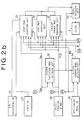
- Figs 2a and 2b show a block diagram of a control unit according to the present invention;
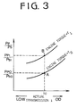
- Fig. 3 is a graph showing relationships between ratio of pressures of oil supplied to drive and driven pulleys and engine torque;
- Fig. 4 is a flowchart showing the operation of a control system according to the present invention;
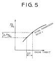
- Fig. 5 is a graph showing a relationship between engine torque and ratio of drive and driven pulley pressures;
- Fig. 6 is a schematic diagram of the drive and driven pulleys and a belt.
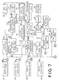
- Figs. 7a and 7b show a main part of a system in another embodiment of the present invention; and
- Fig. 8 is a flowchart showing the operation of the system.
- Referring to Fig. 1, a
crankshaft 10 of anengine 1 is operatively connected to an electromagnetic powder clutch 2 for transmitting the power of theengine 1 to a continuously variable belt-drive automatic transmission 4 through aselector mechanism 3. The output of the belt-drive transmission 4 is transmitted toaxles 8 of vehicle driving wheels 9 through an output shaft 13, a pair ofintermediate reduction gears 5, anintermediate shaft 6, and a differential 7. - The electromagnetic powder clutch 2 comprises an
annular drive member 2a connected tocrankshaft 10 of theengine 1, a driven member 2b secured to aninput shaft 11 of the transmission 4, and a magnetizing coil 2c provided in the driven member 2b. Magnetic Powder is provided in a gap between thedrive member 2a and driven member 2b. When the magnetizing coil 2c is excited by the clutch current, driven member 2b is magnetized to produce a magnetic flux passing through thedrive member 2a. The magnetic powder is aggregated in the gap by the magnetic flux and the driven member 2b is engaged with thedrive member 2a by the powder. On the other hand, when the clutch current is cut off, the drive and drivenmembers 2a and 2b are disengaged from one another. - In the belt-drive transmission 4, the
selector mechanism 3 is provided between theinput shaft 11 and amain shaft 12. Theselector mechanism 3 is provided with a synchromesh mechanism comprising gears, hub, and sleeve for connecting theinput shaft 11 and themain shaft 12 to selectively provide a driving position (D) and a reverse driving position (R). - The continuously variable belt-drive automatic transmission 4 has the
main shaft 12 and the output shaft 13 provided in parallel with themain shaft 12. Thedrive pulley 14 provided with ahydraulic cylinder 14a is mounted on themain shaft 12. The drivenpulley 15 provided with ahydraulic cylinder 15a is mounted on the output shaft 13. Thedrive belt 16 engages with thedrive pulley 14 and the drivenpulley 15.Hydraulic cylinders cylinder 14a is supplied with pressurized oil by an oil pump P from anoil reservoir 17 passing through a line pressure control valve LC and a transmission ratio control valve TR. Thecylinder 15a is applied with pressurized oil from the pump P. The hydraulic control circuit is responsive to vehicle speed, engine speed and throttle valve position for controlling the amount of oil supplied to thecylinders pulleys belt 16 varies to infinitely change the transmission ratio. - An electronic control system for the clutch 2 and the belt-drive transmission 4 has an
engine speed sensor 19, and rotatingspeed sensors drive pulley 14 and the drivenpulley 15. Achoke switch 24 produces an output signal when a choke valve of theengine 1 is closed, and anair conditioner switch 23 produces an output signal at the operation of an air conditioner. Aselector lever 25 connected to theselector mechanism 3 is provided with aselect position sensor 26 for sensing a driving position (D), neutral position (N) and reverse position (R).
Anaccelerator pedal switch 28 is provided for sensing the depression of anaccelerator pedal 27, and athrottle position sensor 29 is provided. - Output signals of the sensors and pulses of the switches are applied to an
electronic control unit 20 which produces a clutch current control signal to the clutch 2 and a control signal for controlling the transmission ratio (i) and a line pressure control singal to the control circuit. - Referring to Figs. 2a and 2b showing the
control unit 20 of Fig. 1, a reverse excitationmode deciding section 32 is applied with engine speed signal Ne of thesensor 19 and drive position signal of theselect position sensor 26. When the engine speed Ne is below 300 rpm, or theselector lever 25 is at the neutral position (N) or a parking position (P), the reverse excitationmode deciding section 32 produces a reverse excitation signal which is applied to anoutput deciding section 33, so that a small reverse current flows in the clutch 2 to release the clutch completely. - A clutch current mode deciding section 34 is applied with signals from the reverse excitation
mode deciding section 32 andaccelerator pedal switch 28, and vehicle speed signal V from drivenpulley speed sensor 22 for deciding driving conditions such as starting mode to produce output signals. The output signals are applied to a startmode providing section 35, dragmode providing section 36, and clutch lock-up engagemode providing section 37. - The start
mode providing section 35 decides clutch current of starting characteristic dependent on the engine speed Ne at ordinary start or at closing of thechoke switch 24 orair conditioner switch 23. The starting characteristic is corrected by signals from the throttle valve opening degree ϑ, vehicle speed V, and driving positions (D) and reverse position (R). - The drag
mode providing section 36 decides a small drag current for providing a drag torque to the clutch 2 for the reduction of clearances formed in the transmission and for the smooth start of the vehicle when theaccelerator pedal 27 is released at a low speed in the driving position and the reverse position. - The clutch lock-up engage
mode providing section 37 decides a lock-up current in response to the vehicle speed V and throttle opening degree ϑ at the driving position and reverse position for entirely engaging the clutch 2. Outputs ofsections output deciding section 33 to control the clutch current. - A system for controlling the transmission ratio and the line pressure will now be described. Output signals NP and NS of the
sensors transmission ratio calculator 40 to produce an actual transmission ratio i in accordance with
throttle position sensor 29 are fed to a desired drive pulley speed table 41 to derive a desired drive pulley speed Npd in accordance with values of the ratio i and signal ϑ. The desired drive pulley speed Npd and the driven pulley speed Ns are fed to a desiredtransmission ratio calculator 42 to calculate a desired transmission ratio id in accordance with the speeds Npd and Ns which corresponds to vehicle speed. - The desired transmission ratio id is fed to a desired transmission ratio changing
speed calculator 43 which produces a desired transmission ratio changing speed did/dt. The speed did/dt is the amount of change of the desired transmission ratio id during a predetermined time interval. Acoefficient setting section 44 is provided for producing coefficients K1 and K2. The actual transmission ratio i, desired transmission ratio id, desired transmission ratio changing speed did/dt and coefficients K1 and K2 are applied to a transmission ratio changing speed calculator 45 to produce a transmission ratio changing speed di/dt from the following formula.

In the formula, the term of (id - i) is a control quantity dependent on the difference between the desired and actual transmission ratios and did/dt is a term for advancing the delay in phase caused by a first order lag in the system. - The speed di/dt and actual ratio i are applied to a duty ratio table 46 to derive a duty ratio D in accordance with

valve 48 through adriver 47. Thevalve 48 is provided in the hydraulic circuit, for shifting a spool of the transmission ratio control valve TR to control the transmission ratio. - On the other hand, engine speed Ne from the
engine speed sensor 19 and throttle opening degree ϑ from thethrottle position sensor 29 are applied to an engine torque table 50 to derive an engine torque T. The engine torque T and the actual transmission ratio i from thecalculator 40 is applied to a desired line pressure table 51 to derive a desired line pressure PLD. - In a hydraulic circuit of the control system, oil pressure discharged from the pump varies in accordance with the change of the engine speed Ne, so that a maximum line pressure PLM also varies. In order to detect the variance of the maximum line pressure PLM, the control unit is provided with a maximum line pressure table 52 to which the engine speed Ne and the actual transmission ratio i are supplied. Therefore, the maximum line pressure PLM is obtained.
- The desired line pressure PLD and the maximum line pressure PLM are applied to a reduced
line pressure calculator 53 wherein a reduced line pressure PLR is calculated based on the proportion of the desired line pressure PLD to the maximum line pressure PLM. The reduced line pressure PLR is applied to a duty ratio table 54 to derive a duty ratio DL corresponding to the reduced line pressure PLR. The duty ratio DL is supplied todriver 55 which operates a solenoid operated on-offvalve 56 at the duty ratio. Thevalve 56 is provided in the hydraulic circuit, for shifting a spool of the line pressure control valve LC to control the line pressure. - Fig. 3 shows relationship between engine torque and ratio of pressure PP of oil supplied to drive
pulley cylinder 14a to pressure PS of oil supplied to drivenpulley cylinder 15a. When engine torque TO increases to engine torque T₁, the ratio PP/PS for keeping an actual transmission ratio ic changes from a ratio PPO/PSO at a point A on line TO to a ratio PP1/PS1 at a point B on line T₁. In other words, in order to keep the transmission ratio ic, the ratio PPO/PSO should be changed to the ratio PP1/PS1. - Fig. 5 shows a correcting quantity ΔPP/PS corresponding to an increment ΔT of the engine torque T. The system of the present invention is to correct transmission ratio with the correcting quantity ΔPP/PS.
- The control system of the present invention is provided with a correcting quantity table 57 to which engine torque T derived from the engine torque table 50, desired line pressure PLD from the desired line pressure table 51 and the actual transmission ratio i from the actual
transmission ratio calculator 40 are fed. A correcting quantity Δ(PP/PS) is derived from the table and applied to a dutyratio correcting section 49. The desired line pressure PLD is further applied to the dutyratio correcting section 49. Thus, the duty ratio D is corrected to a corrected duty ratio Dc in accordance with the desired line pressure PLD and correcting quantity ΔPP/PS. The duty ratio Dc is supplied to the solenoid operated on-offvalve 48 through thedriver 47. - In operation, while the vehicle stops,
cylinder 15a of the drivenpulley 15 is supplied with line pressure, and thecylinder 14a of thedrive pulley 14 is drained, since the NP, Ns, ϑ are zero and duty ratio D is zero. Thus, in the pulley and belt device of the continuously variable belt-drive transmission, thedrive belt 16 engages with the drivenpulley 15 at a maximum running diameter to provide the largest transmission ratio (low speed stage). - When the
accelerator pedal 27 is depressed, the clutch current increases progressively with increase of engine speed. The electromagnetic clutch 2 is gradually engaged, transmitting the engine power to the drivepulley 14. The power of the engine is transmitted to the output shaft 13 at the largest transmission ratio by thedrive belt 16 and drivenpulley 15, and further transmitted to axles of the driving wheels 9. Thus, the vehicle is started. When the vehicle speed (output signal Ns) exceeds a predetermined value, the clutch 2 is entirely engaged. - When the throttle valve is opened for acceleration of the vehicle, the desired transmission ratio id is calculated at the
calculator 42 based on the desired drive pulley speed derived from the table 41 and on the throttle position ϑ. Further, the desired transmission ratio changing speed did/dt and transmission ratio changing speed di/dt are calculated atcalculators 43 and 45 based on the actual transmission ratio i, desired transmission ratio id and coefficients K₁ and K₂. The transmission ratio changing speed di/dt is fed to the duty ratio table 46, so that duty ratio D forvalve 48 is obtained from the table 46. - When the accelerator pedal is released, the transmission ratio changing speed di/dt becomes negative. Accordingly the value of the duty ratio D becomes larger than the neutral value, so that oil is supplied to the
cylinder 14a to upshift the transmission. When the actual transmission ratio i reaches the desired transmission ratio id, the changing speed di/dt becomes zero, so that the upshifting operation stops. - When the drive pulley speed is substantially constant, the desired transmission ratio id calculated based on the desired drive pulley speed Npd and the driven pulley speed Ns has the same value as the desired transmission ratio calculated based on the driven pulley speed Ns and throttle opening degree ϑ. In a range where the drive pulley speed varies, a proper desired transmission ratio id is calculated based on a desired drive pulley speed Npd derived from the table 41.
- As the difference between the desired ratio id and actual ratio i becomes large and the desired transmission ratio changing speed di/dt becomes large, the duty ratio D for the
valve 48 becomes large, thereby increasing the actual transmission ratio changing speed di/dt. - When the opening degree of the throttle valve is reduced for deceleration, the duty ratio D is reduced along a low engine speed line, thereby draining the
cylinder 14a. Thus, the transmission is downshifted. The transmission changing speed at downshifting increases with reducing of the duty ratio D. - The control operation of line pressure will be described hereinafter. From the engine torque table 50, a torque T is obtained in accordance with throttle opening degree ϑ and engine speed Ne, which is applied to desired line pressure table 51. The desired line pressure PLD and the maximum line pressure PLM obtained from the table 52 are fed to the reduced
line pressure calculator 53. Thecalculator 53 calculates a reduced line pressure PLR. The solenoid operated on-offvalve 56 is operated at a duty ratio DL corresponding to the reduced line pressure PLR. The line pressure is applied tocylinder 15a to hold thebelt 16 at a necessary minimum force, the transmitting torque at which is slightly larger than torque T. Thus, power is transmitted through the transmission without slipping of the belt. - The operation is further described by the flowchart shown in Fig. 4.
- At a step S101, the engine torque TO is obtained. At a step S102, the actual transmission ratio ic and the ratio PPO/PSO at the engine torque TO, namely at the point A in Fig. 3, is obtained. The increased engine torque T₁ and the ratio PP1/PS1 at the engine torque T₁ at the transmission ratio ic, namely at the point B, is obtained at a step S103. The correcting quantity Δ(PP/PS) is calculated at a step S104 and the duty ratio D is corrected dependent on the quantity Δ(PP/PS) to the corrected duty ratio Dc at a step S105. Thus, the pulley pressure ratio PP/PS is increased to the ratio PP1/PS1 so that the transmission ratio ic is exactly controlled to a desired transmission ratio.
- In the above described system, cases frequently occur where the engine torque increases during the upshifting or downshifting of the transmission. In the case that the drive pulley cylinder pressure is increased during the downshifting, speed of the downshifting is reduced. During the upshifting, speed of the upshifting is increased.
- The system shown in Figs. 7a and 7b is to resolve such a problem. The same parts as the system of Figs. 2a and 2b are identified by the same references as Figs. 2a and 2b.
- The system of Figs. 7a and 7b is provided with an actual transmission ratio changing
speed calculator 57a where actual transmission ratio changing speed dia/dt is calculated based on change of the transmission ratio i. That is to say, the actual transmission ratio changing speed dia/dt is obtained by differentiating the changing amount of the transmission ratio by the elapsed time t. The changing speed dia/dt is applied to a dutyratio correcting section 49a to which actual transmission ratio i, engine torque T derived from the engine torque table 50 and desired transmission ratio PLD are fed. In the dutyratio correcting section 49a, a ratio k, which is a ratio of oil pressures PP and PS applied to the cylinders of the drive and driven pulleys, is obtained in dependence on the torque T and actual transmission ratio. The duty ratio D is corrected in the correctingsection 49a to produce a corrected duty ratio Dc. The duty ratio Dc is supplied to solenoid operated on-offvalve 48 through thedriver 47. Thus, the pressure in the drive pulley cylinder is properly increased. Fig. 8 shows the operation of the system.
Claims (3)
- A control system for a continuously variable transmission (4) for transmitting power of an internal combustion engine (1) mounted on a motor vehicle, said system comprising
a drive pulley (14) having a hydraulically shiftable disc (14a) and a hydraulic cylinder for operating said disc (14a), a driven pulley (15) having a hydraulically shiftable disc (15a) and a hydraulic cylinder for operating said disc (15a), a belt (16) engaged with said both pulleys;
a first hydraulic circuit having a pump for supplying oil to both of the hydraulic cylinders, a transmission ratio control valve for controlling the oil supplied to said cylinder of said drive pulley to change the transmission ratio (i);
a second hydraulic circuit having a solenoid operated valve for operating said transmission ratio control valve, a throttle position sensor (29) for detecting the position of a throttle valve to control power of said engine (1) and arranged to produce a throttle position signal;
an engine speed sensor (19) for detecting engine speed (Ne) and for producing an engine speed signal; and
a control unit (20) for controlling said solenoid operated valve, said control unit including an actual transmission ratio calculator (40) responsive to speed of said drive and driven pulleys for producing an actual transmission ratio signal,
calculator means (42) for calculating a desired transmission ratio in accordance with driving conditions of the vehicle, and means (46, 47) for producing a driving signal to operate the solenoid valve so as to control the transmission ratio to the desired transmission ratio;
detector means (50) responsive to said throttle position signal and said engine speed signal to detect an increase of output torque of the engine (1) and to produce an engine torque increase signal, and desired line pressure calculating means (51) responsive to said actual transmission ratio and said engine torque increase signals to produce a desired line pressure signal; and
control means (55, 56) to operate said solenoid operated valve;
characterised in the provision of calculator means (52) responsive to said engine speed signal and said actual transmission ratio signal and arranged to calculate a maximum line pressure in accordance with driving conditions of said vehicle;
correcting means (57) responsive to said engine torque increase signal, said actual transmission ratio signal and said desired line pressure signal to produce a correcting quantity signal so as to control pressure of oil supplied to said hydraulic cylinders;
a reduced line pressure calculator (53) responsive to said desired line pressure signal and maximum line pressure signal provided to produce a reduced line pressure signal in order to reduce said pressure of oil; and wherein
the control means (55, 56) is responsive to said correcting quantity signal and reduced line pressure signal to operate said solenoid operated valve so as to prevent downshifting of said transmission ratio in spite of existence of said engine torque increase signal. - The system according to claim 1,
characterised in that the correcting means corrects a difference between pressures of oils in the cylinder of the drive pulley and the cylinder of the driven pulley. - The system according to claim 1,
characterised in that the correcting means corrects the driving signal in accordance with speed of actual transmission ratio changing speed.
Applications Claiming Priority (4)
| Application Number | Priority Date | Filing Date | Title |
|---|---|---|---|
| JP63040256A JP2900257B2 (en) | 1988-02-22 | 1988-02-22 | Transmission control device for continuously variable transmission |
| JP40255/88 | 1988-02-22 | ||
| JP63040255A JP2741029B2 (en) | 1988-02-22 | 1988-02-22 | Transmission control device for continuously variable transmission |
| JP40256/88 | 1988-02-22 |
Publications (3)
| Publication Number | Publication Date |
|---|---|
| EP0330422A2 EP0330422A2 (en) | 1989-08-30 |
| EP0330422A3 EP0330422A3 (en) | 1990-10-03 |
| EP0330422B1 true EP0330422B1 (en) | 1994-01-05 |
Family
ID=26379704
Family Applications (1)
| Application Number | Title | Priority Date | Filing Date |
|---|---|---|---|
| EP89301661A Expired - Lifetime EP0330422B1 (en) | 1988-02-22 | 1989-02-21 | Control system for a continuously variable transmission |
Country Status (3)
| Country | Link |
|---|---|
| US (1) | US4923433A (en) |
| EP (1) | EP0330422B1 (en) |
| DE (1) | DE68911955T2 (en) |
Families Citing this family (12)
| Publication number | Priority date | Publication date | Assignee | Title |
|---|---|---|---|---|
| JP2692254B2 (en) * | 1989-04-21 | 1997-12-17 | 日産自動車株式会社 | Transmission control device for continuously variable transmission |
| JPH0341252A (en) * | 1989-07-06 | 1991-02-21 | Mazda Motor Corp | Controller for vehicle equipped with continuously variable transmission |
| JPH03172674A (en) * | 1989-11-30 | 1991-07-26 | Fuji Heavy Ind Ltd | Control device for continuously variable transmission |
| JPH03189456A (en) * | 1989-12-18 | 1991-08-19 | Mazda Motor Corp | Speed change control device for continuously variable transmission |
| JP2900286B2 (en) * | 1990-10-31 | 1999-06-02 | 富士重工業株式会社 | Control device for continuously variable transmission |
| JP2900194B2 (en) * | 1991-01-22 | 1999-06-02 | 富士重工業株式会社 | Pressure control device for continuously variable transmission for vehicles |
| US5207617A (en) * | 1991-06-27 | 1993-05-04 | Toyota Jidosha Kabushiki Kaisha | Hydraulic control apparatus for continuously variable power transmitting system including reversing gear device and auxiliary transmission |
| US5776028A (en) * | 1995-09-01 | 1998-07-07 | Honda Giken Kogyo Kabushiki Kaisha | Belt-type continuously variable transmission |
| TW567287B (en) * | 2001-05-15 | 2003-12-21 | Honda Motor Co Ltd | Hydraulic controller |
| JP3905445B2 (en) * | 2002-09-12 | 2007-04-18 | ジヤトコ株式会社 | Hydraulic control device for V-belt type continuously variable transmission |
| JP4238895B2 (en) * | 2006-08-11 | 2009-03-18 | トヨタ自動車株式会社 | Shift control device for continuously variable transmission for vehicle |
| CN104334929B (en) * | 2012-06-08 | 2016-05-04 | 加特可株式会社 | Buncher and hydraulic control method thereof |
Citations (1)
| Publication number | Priority date | Publication date | Assignee | Title |
|---|---|---|---|---|
| EP0258005A1 (en) * | 1986-08-23 | 1988-03-02 | Fuji Jukogyo Kabushiki Kaisha | Control system for a continuously variable transmission |
Family Cites Families (11)
| Publication number | Priority date | Publication date | Assignee | Title |
|---|---|---|---|---|
| JPS5790450A (en) * | 1980-11-27 | 1982-06-05 | Nippon Denso Co Ltd | Automatic change gear control apparatus for vehicle |
| JPS59159456A (en) * | 1983-02-26 | 1984-09-10 | Toyota Motor Corp | Hydraulic apparatus for belt-type stepless speed change gear |
| JPS6053257A (en) * | 1983-08-31 | 1985-03-26 | Fuji Heavy Ind Ltd | Electronic controller for stepless transmission |
| JPS60222649A (en) * | 1984-04-19 | 1985-11-07 | 富士重工業株式会社 | Controller for change gear ratio of electronic type infinitely variable gear |
| JPS61119860A (en) * | 1984-11-16 | 1986-06-07 | Fuji Heavy Ind Ltd | Electronic control device for continuously variable transmission |
| JPS624647A (en) * | 1985-06-29 | 1987-01-10 | Fuji Heavy Ind Ltd | Control device of continuously variable speed change gear |
| JPS62116320A (en) * | 1985-11-18 | 1987-05-27 | Fuji Heavy Ind Ltd | Control unit for continuously variable transmission |
| JPS62122836A (en) * | 1985-11-22 | 1987-06-04 | Fuji Heavy Ind Ltd | Controller for continuously variable transmission |
| JPS62143744A (en) * | 1985-12-19 | 1987-06-27 | Fuji Heavy Ind Ltd | Transmission gear ratio control of continuously variable transmission for vehicle |
| JPS62221931A (en) * | 1986-03-25 | 1987-09-30 | Fuji Heavy Ind Ltd | Control device for continuously variable transmission |
| JPH07456B2 (en) * | 1986-09-19 | 1995-01-11 | 日産自動車株式会社 | Shift control device for continuously variable transmission |
-
1989
- 1989-02-09 US US07/310,067 patent/US4923433A/en not_active Expired - Lifetime
- 1989-02-21 EP EP89301661A patent/EP0330422B1/en not_active Expired - Lifetime
- 1989-02-21 DE DE68911955T patent/DE68911955T2/en not_active Expired - Lifetime
Patent Citations (1)
| Publication number | Priority date | Publication date | Assignee | Title |
|---|---|---|---|---|
| EP0258005A1 (en) * | 1986-08-23 | 1988-03-02 | Fuji Jukogyo Kabushiki Kaisha | Control system for a continuously variable transmission |
Also Published As
| Publication number | Publication date |
|---|---|
| EP0330422A2 (en) | 1989-08-30 |
| EP0330422A3 (en) | 1990-10-03 |
| US4923433A (en) | 1990-05-08 |
| DE68911955T2 (en) | 1994-05-26 |
| DE68911955D1 (en) | 1994-02-17 |
Similar Documents
| Publication | Publication Date | Title |
|---|---|---|
| EP0231059B1 (en) | Control system for a continuously variable transmission | |
| EP0364270B1 (en) | Transmission ratio control system for a continuously variable transmission | |
| US4730712A (en) | System for controlling a clutch for a motor vehicle | |
| EP0213852B1 (en) | Continuously variable transmission oil pressure control | |
| EP0364269B1 (en) | Transmission ratio control system for a continuously variable transmission | |
| EP0242127B1 (en) | System for controlling a clutch for a vehicle | |
| EP0329407B1 (en) | A control system for a clutch for a motor vehicle | |
| EP0181786B1 (en) | Control system for an infinitely variable transmission | |
| EP0297727A2 (en) | System for controlling a continuously variable transmission having a torque converter | |
| EP0213948B1 (en) | Oil pressure control system for continuously variable transmission | |
| US4923433A (en) | Transmission ratio control system for a continuously variable transmission | |
| EP0239365A2 (en) | Transmission ratio control system for a continuously variable transmission | |
| US4850935A (en) | Transmission ratio control system for a continuously variable transmission | |
| EP0207227A1 (en) | Control system for an infinitely variable transmission | |
| EP0207603B1 (en) | Control system for an infinitely variable transmission | |
| EP0239415A2 (en) | Control system for a continuously variable transmission | |
| US5209332A (en) | Control system for a clutch of a motor vehicle | |
| US4825991A (en) | Control system for a clutch for a vehicle | |
| US5217086A (en) | Control system for a vehicle | |
| EP0251571B1 (en) | Control system for a clutch for a vehicle | |
| EP0228800B1 (en) | System for controlling the pressure of oil in a system for a continuously variable transmission | |
| US4977988A (en) | Control system for a clutch for a vehicle | |
| EP0240281B1 (en) | Control system for an electromagnetic clutch for a vehicle | |
| US4848544A (en) | Control system for a clutch for a vehicle | |
| US4830155A (en) | Control system for a clutch for a vehicle |
Legal Events
| Date | Code | Title | Description |
|---|---|---|---|
| PUAI | Public reference made under article 153(3) epc to a published international application that has entered the european phase |
Free format text: ORIGINAL CODE: 0009012 |
|
| 17P | Request for examination filed |
Effective date: 19890306 |
|
| AK | Designated contracting states |
Kind code of ref document: A2 Designated state(s): DE GB IT NL |
|
| PUAL | Search report despatched |
Free format text: ORIGINAL CODE: 0009013 |
|
| AK | Designated contracting states |
Kind code of ref document: A3 Designated state(s): DE GB IT NL |
|
| 17Q | First examination report despatched |
Effective date: 19910820 |
|
| GRAA | (expected) grant |
Free format text: ORIGINAL CODE: 0009210 |
|
| AK | Designated contracting states |
Kind code of ref document: B1 Designated state(s): DE GB IT NL |
|
| PG25 | Lapsed in a contracting state [announced via postgrant information from national office to epo] |
Ref country code: IT Free format text: LAPSE BECAUSE OF FAILURE TO SUBMIT A TRANSLATION OF THE DESCRIPTION OR TO PAY THE FEE WITHIN THE PRESCRIBED TIME-LIMIT;WARNING: LAPSES OF ITALIAN PATENTS WITH EFFECTIVE DATE BEFORE 2007 MAY HAVE OCCURRED AT ANY TIME BEFORE 2007. THE CORRECT EFFECTIVE DATE MAY BE DIFFERENT FROM THE ONE RECORDED. Effective date: 19940105 Ref country code: NL Effective date: 19940105 |
|
| REF | Corresponds to: |
Ref document number: 68911955 Country of ref document: DE Date of ref document: 19940217 |
|
| NLV1 | Nl: lapsed or annulled due to failure to fulfill the requirements of art. 29p and 29m of the patents act | ||
| PLBE | No opposition filed within time limit |
Free format text: ORIGINAL CODE: 0009261 |
|
| STAA | Information on the status of an ep patent application or granted ep patent |
Free format text: STATUS: NO OPPOSITION FILED WITHIN TIME LIMIT |
|
| 26N | No opposition filed | ||
| REG | Reference to a national code |
Ref country code: GB Ref legal event code: 746 Effective date: 19981222 |
|
| REG | Reference to a national code |
Ref country code: GB Ref legal event code: IF02 |
|
| PGFP | Annual fee paid to national office [announced via postgrant information from national office to epo] |
Ref country code: GB Payment date: 20050216 Year of fee payment: 17 |
|
| PG25 | Lapsed in a contracting state [announced via postgrant information from national office to epo] |
Ref country code: GB Free format text: LAPSE BECAUSE OF NON-PAYMENT OF DUE FEES Effective date: 20060221 |
|
| GBPC | Gb: european patent ceased through non-payment of renewal fee |
Effective date: 20060221 |
|
| PGFP | Annual fee paid to national office [announced via postgrant information from national office to epo] |
Ref country code: DE Payment date: 20080214 Year of fee payment: 20 |