EP0329706B1 - Faceplate assembly for color cathode ray tube and process of securing shadow mask support structure to the faceplate of said tube - Google Patents
Faceplate assembly for color cathode ray tube and process of securing shadow mask support structure to the faceplate of said tube Download PDFInfo
- Publication number
- EP0329706B1 EP0329706B1 EP87907878A EP87907878A EP0329706B1 EP 0329706 B1 EP0329706 B1 EP 0329706B1 EP 87907878 A EP87907878 A EP 87907878A EP 87907878 A EP87907878 A EP 87907878A EP 0329706 B1 EP0329706 B1 EP 0329706B1
- Authority
- EP
- European Patent Office
- Prior art keywords
- faceplate
- support structure
- shadow mask
- securing
- mask
- Prior art date
- Legal status (The legal status is an assumption and is not a legal conclusion. Google has not performed a legal analysis and makes no representation as to the accuracy of the status listed.)
- Expired - Lifetime
Links
- 238000000034 method Methods 0.000 title claims abstract description 28
- 239000011521 glass Substances 0.000 claims abstract description 61
- OAICVXFJPJFONN-UHFFFAOYSA-N Phosphorus Chemical compound [P] OAICVXFJPJFONN-UHFFFAOYSA-N 0.000 claims abstract description 39
- 239000011888 foil Substances 0.000 claims abstract description 39
- 238000004873 anchoring Methods 0.000 claims abstract description 11
- 229910052751 metal Inorganic materials 0.000 claims description 30
- 239000002184 metal Substances 0.000 claims description 30
- 230000000149 penetrating effect Effects 0.000 claims description 20
- 239000004568 cement Substances 0.000 claims description 11
- 238000010438 heat treatment Methods 0.000 claims description 10
- 239000007769 metal material Substances 0.000 claims description 9
- 238000000137 annealing Methods 0.000 claims description 8
- 239000000463 material Substances 0.000 claims description 8
- 238000012216 screening Methods 0.000 claims description 5
- 239000000919 ceramic Substances 0.000 claims description 4
- 238000003825 pressing Methods 0.000 claims description 4
- 230000001143 conditioned effect Effects 0.000 claims description 2
- 229910001092 metal group alloy Inorganic materials 0.000 claims 1
- 238000007789 sealing Methods 0.000 abstract description 8
- 230000002093 peripheral effect Effects 0.000 abstract description 5
- 230000004048 modification Effects 0.000 abstract 1
- 238000012986 modification Methods 0.000 abstract 1
- 238000004519 manufacturing process Methods 0.000 description 9
- 230000035515 penetration Effects 0.000 description 7
- 238000003466 welding Methods 0.000 description 7
- 230000008901 benefit Effects 0.000 description 6
- 238000010894 electron beam technology Methods 0.000 description 5
- 230000013011 mating Effects 0.000 description 4
- 239000000203 mixture Substances 0.000 description 4
- 229910000640 Fe alloy Inorganic materials 0.000 description 3
- 229910045601 alloy Inorganic materials 0.000 description 3
- 239000000956 alloy Substances 0.000 description 3
- 238000005516 engineering process Methods 0.000 description 3
- 230000004888 barrier function Effects 0.000 description 2
- 230000015556 catabolic process Effects 0.000 description 2
- 239000011248 coating agent Substances 0.000 description 2
- 238000000576 coating method Methods 0.000 description 2
- 230000003750 conditioning effect Effects 0.000 description 2
- 238000010276 construction Methods 0.000 description 2
- 239000000356 contaminant Substances 0.000 description 2
- 230000000694 effects Effects 0.000 description 2
- 238000003384 imaging method Methods 0.000 description 2
- 238000009434 installation Methods 0.000 description 2
- 239000000126 substance Substances 0.000 description 2
- 239000000725 suspension Substances 0.000 description 2
- 238000009736 wetting Methods 0.000 description 2
- 241000937413 Axia Species 0.000 description 1
- 241000272534 Struthio camelus Species 0.000 description 1
- WYTGDNHDOZPMIW-RCBQFDQVSA-N alstonine Natural products C1=CC2=C3C=CC=CC3=NC2=C2N1C[C@H]1[C@H](C)OC=C(C(=O)OC)[C@H]1C2 WYTGDNHDOZPMIW-RCBQFDQVSA-N 0.000 description 1
- 229910052782 aluminium Inorganic materials 0.000 description 1
- XAGFODPZIPBFFR-UHFFFAOYSA-N aluminium Chemical compound [Al] XAGFODPZIPBFFR-UHFFFAOYSA-N 0.000 description 1
- 239000006227 byproduct Substances 0.000 description 1
- 239000003990 capacitor Substances 0.000 description 1
- 229910010293 ceramic material Inorganic materials 0.000 description 1
- 238000004140 cleaning Methods 0.000 description 1
- 230000000295 complement effect Effects 0.000 description 1
- 239000002131 composite material Substances 0.000 description 1
- 239000004020 conductor Substances 0.000 description 1
- 230000001419 dependent effect Effects 0.000 description 1
- 230000002708 enhancing effect Effects 0.000 description 1
- 239000005357 flat glass Substances 0.000 description 1
- 239000012530 fluid Substances 0.000 description 1
- 239000012535 impurity Substances 0.000 description 1
- 230000006698 induction Effects 0.000 description 1
- 238000011900 installation process Methods 0.000 description 1
- 238000005304 joining Methods 0.000 description 1
- 239000002574 poison Substances 0.000 description 1
- 231100000614 poison Toxicity 0.000 description 1
- 230000000284 resting effect Effects 0.000 description 1
- 239000002002 slurry Substances 0.000 description 1
- 230000000087 stabilizing effect Effects 0.000 description 1
- 238000009966 trimming Methods 0.000 description 1
Images





Classifications
-
- H—ELECTRICITY
- H01—ELECTRIC ELEMENTS
- H01J—ELECTRIC DISCHARGE TUBES OR DISCHARGE LAMPS
- H01J29/00—Details of cathode-ray tubes or of electron-beam tubes of the types covered by group H01J31/00
- H01J29/02—Electrodes; Screens; Mounting, supporting, spacing or insulating thereof
- H01J29/06—Screens for shielding; Masks interposed in the electron stream
- H01J29/07—Shadow masks for colour television tubes
-
- H—ELECTRICITY
- H01—ELECTRIC ELEMENTS
- H01J—ELECTRIC DISCHARGE TUBES OR DISCHARGE LAMPS
- H01J29/00—Details of cathode-ray tubes or of electron-beam tubes of the types covered by group H01J31/00
- H01J29/02—Electrodes; Screens; Mounting, supporting, spacing or insulating thereof
- H01J29/06—Screens for shielding; Masks interposed in the electron stream
- H01J29/07—Shadow masks for colour television tubes
- H01J29/073—Mounting arrangements associated with shadow masks
-
- H—ELECTRICITY
- H01—ELECTRIC ELEMENTS
- H01J—ELECTRIC DISCHARGE TUBES OR DISCHARGE LAMPS
- H01J2229/00—Details of cathode ray tubes or electron beam tubes
- H01J2229/07—Shadow masks
- H01J2229/0722—Frame
Definitions
- This invention generally relates to color cathode ray picture tubes and, specifically, to a novel front assembly for color tubes that have a tension foil shadow mask.
- the invention also relates to a process of securing a support structure to a glass faceplate for use in the manufacture of such tubes.
- the invention is useful in color tubes of various types including those used in home entertainment television receivers, and those used in medium-resolution and high-resolution tubes intended for color monitors.
- the use of the tension foil mask and a flat faceplate provides many advantages and benefits in comparison with the conventional curved or domed shadow mask. Chief among these is a greater power-handling capability which makes possible as much as a three-fold increase in brightness.
- the conventional curved shadow mask which is not under tension, tends to "dome" in high-brightness picture areas where the intensity of electron bombardment is greatest. Color impurities result as the mask moves closer to the faceplate. Being under high tension, the tension foil mask does not dome or otherwise move in relation to the faceplate. Therefore, it has greater brightness potential while maintaining color purity.
- the tension foil shadow mask is a part of the cathode ray tube front assembly, and is located in close adjacency to the faceplate.
- the front assembly comprises the faceplate with its deposits of light-emitting phosphors, a shadow mask, and support means for the mask.
- the term "shadow mask” means an apertured metallic foil which may have a thickness, by way of example, of about one mil or less.
- the mask must be supported in high tension a predetermined distance from the inner surface of the cathode ray tube faceplate. This distance is known as the "Q-distance.”
- the high tension may be in the range of 20 to 40 kpsi (1406 kolograms/sq.cm to 2812 kilograms/sq.cm).
- the shadow mask acts as a color-selection electrode, or parallax barrier, which ensures that each of the three color-beams lands only on its assigned phosphor deposits.
- the requirements for the support means for the shadow mask are stringent.
- the shadow mask must be mounted under high tension.
- the mask support means must be of high strength so that the mask is held immovable. An inward movement of the mask of as little as one-tenth of a mil (.00025 cm) is significant in that guard band may be expended.
- the shadow mask support means must be of such configuration and material composition as to be compatible with the means to which it is attached. As an example, if the support means is attached to glass such as the inner surface of the faceplate, the support means must have about the same thermal coefficient of expansion as that of the glass. The support means must provide a suitable surface for mounting the mask.
- the support means must be of a composition such that the mask can be welded onto it by electrical resistance welding or by laser welding.
- the support surface preferably is of such flatness that no voids can exist between the metal of the mask and the support structure to prevent the intimate metal-to-metal contact required for proper welding.
- Means for securing the shadow mask support to the inner surface of the faceplate may comprise a cement in the form of a devitrifying glass frit. While satisfactory in the main, cement of this type has significant disadvantages in that it is difficult to handle and apply in production, and it tends to create "pockets" in which screening fluids may lodge and be released later as contaminants. Also, the composition of the frit itself is subject to chemical breakdown when exposed to strong chemicals normally applied during the photoscreening process, and the byproducts of the breakdown may contaminate and poison the tube inner environment.
- a tension mask registration and supporting system is disclosed by Strauss in U.S. Patent No. US-A-4,547,696 of common ownership herewith.
- a frame dimensioned to enclose the screen comprises first and second space-apart surfaces.
- a tensed foil shadow mask has a peripheral portion bonded to a second surface of the frame.
- the frame is registered with the faceplate by ball-and-groove indexing means.
- the shadow mask is sandwiched between the frame and a stabilizing or stiffening member.
- the frame When the system is assembled, the frame is located between the sealing lands of the faceplate and a funnel, with the stiffening member projecting from the frame into the funnel. While the system is feasible and provides an effective means for holding a mask under high tension and rigidly planoparallel with a flat faceplate, weight is added to the cathode ray tube, and additional process steps are required in manufacture.
- U.S. Patent No. US-A-3,890,526 discloses a faceplate mounting structure for a curved color selection electrode for a cathode ray tube having a curved faceplate.
- the mounting structure includes four sheet-metal studs comprising part of an electrode suspension device.
- the studs are embedded in the curved faceplate by a hot sealing operation.
- the disclosure includes a description of machine for installing the studs, which provides means for flame-heating the studs, and simultaneously the areas of the faceplate which receive them, after which the studs are automatically pressed into the glass.
- a glass-to-metal ceramic seal or bond is described by Daniel I. Pomerantz of the Mallory Laboratory for Physical Science, Burlington, Mass.
- a flat piece of glass is placed in contact with a flat piece of metal.
- the two pieces are heated to a temperature about 250 degrees C. below the softening point of the glass.
- a direct current is applied across the two parts to form what is in effect a capacitor, with the metal part polarized positive. The result is said to be a bonding of the two parts.
- No commercial application of this process to the cathode ray tube construction art is presently known. (Source: “Sealed with a Kilovolt," an article by David H. Surgan. The Electronic Engineer , September 1958. Pp. 16-17.
- the invention aims to provide an improved front assembly for tension foil shadow mask tubes.
- the present invention therefore provides a front assembly for a color cathode ray tube including a faceplate having on its inner surface a centrally disposed phosphor screen, said assembly including a shadow mask support structure having an undulated cross-section and substantially surrounding the phosphor screen for supporting the shadow mask in tension upon said undulated structure, and means for securing said undulated structure to the faceplate.
- the improved shadow mask support structure of the invention has the advantage of being low in cost and light in weight. Further, the support structure simplifies manufacture and lowers manufacturing costs.
- the present invention therefore provides in the independent claims 1, 12 and 17 a faceplate assembly for a color cathode ray tube comprising a glass faceplate having on its inner surface a centrally disposed phosphor screen, and a foil shadow mask mounted in tension on a mask support structure located on opposed sides of the screen, said mask support structure physically penetrating said faceplate for permanent, cementless anchoring of said structure to said faceplate, with the embedment of said mask support structure being of such depth as to cause said structure to resist tensile forces created by said mask.
- the present invention also relates in claim 19 to a process of securing a support structure for a tensed foil shadow mask to a glass faceplate having a centrally disposed phosphor screening area on an inner surface thereof, said process including the steps of providing a frame-like support structure for receiving and supporting said shadow mask in tension, said support structure having a mounting surface suitable for securing said mask thereon, and a base portion adapted for physically penetrating said faceplate; providing a faceplate at least said surface of which is heated to a predetermined temperature at which it is conditioned to be penetrated by said support structure; pressing said structure into said faceplate through said inner surface on opposed sides of said screen, causing said base portion to penetrate to a depth effective both to secure said structure to said faceplate against the tensile forces imparted by said mask, and to position said mounting surface at a predetermined distance from said faceplate inner surface, whereby said mounting surface is positioned for receiving said foil shadow mask in tension in appropriate spaced relationship to said faceplate inner surface; and mounting said foil mask in tension
- One advantage of the improved faceplate assembly is that it assures that a tensed foil shadow mask is more securely mounted on the faceplate.
- this improved assembly provides means, for permanently mounting a support structure for a shadow mask on a faceplate without the need for a special cement.
- the improved process of the invention secures a tensed foil shadow mask support to the faceplate inner surface in such manner as to insure that no pockets for the lodgment of contaminants during manufacture.
- Figure 1 depicts a video monitor, generally designated 10, that houses a color cathode ray tube, generally designated 12, having a novel front assembly according to the invention.
- the monitor-associated tube is notable for the flat imaging area 14 that makes possible the display of images in undistorted form.
- Imaging area 14 also offers a more efficient use of screen area as the corners are relatively square in comparison with the more rounded corners of the conventional cathode ray tube.
- Front assembly 15 for a high-resolution color cathode ray tube is depicted, the general scope of which is indicated by the bracket.
- Front assembly 15 includes a glass faceplate 16 noted as being flat, or alternately, "substantially" flat in that it may have finite horizontal and vertical radii.
- Faceplate 16 depicted in this embodiment of the invention as being planar and flangeless, has on its inner surface a centrally disposed phosphor target area 18, on which is deposited an electrically conductive film 19.
- Phosphor target area18 and conductive film 19 comprise the electron beam target area, commonly termed a "screen,” generally designated 20, which serves, during manufacture, for receiving a uniform coat of phosphor slurry.
- Conductive film 19, which is deposited on the phosphor deposits in a final step typically consists of a very thin, light-reflective, electron-pervious film of aluminum.
- Sealing area 21 is represented as having three substantially radially oriented first indexing V-grooves therein, only two grooves 26A and 26B being shown in Figure 4.
- the indexing grooves preferably are peripherally located at equal angular intervals about the center of faceplate 16; that is, at 120-degree intervals. Indexing grooves 26A and 26B are shown in Figure 4.
- the third indexing groove is not shown; however, it is also located in peripheral sealing area 21 equidistantly from indexing elements 26A and 26B.
- the V-shaped indexing grooves provide for indexing faceplate 16 in conjunction with a mating envelope member, as will be shown.
- Funnel 22 has a funnel sealing area 28 with second indexing elements or grooves 30A and 30B therein in like orientation, and depicted in Figure 4 in facing adjacency with the first indexing elements 26A and 26B.
- Ball means 32A and 32B which provide complementary rounded indexing means, are conjugate with the indexing grooves or elements 26A and 26B and 30A and 30B for registering the faceplate 16 and the funnel 22.
- the first indexing elements together with the ball means are also utilized as indexing means during the photoscreening of the phosphor deposits on the faceplate.
- Front assembly 15 includes a tension foil mask support structure, generally designated 34, secured to the inner surface of faceplate 16 between screen 20 and peripheral sealing area 21 and enclosing the phosphor target 18.
- the support structure provides for supporting a tension foil shadow mask 35 a predetermined "Q-distance" from the inner surface of faceplate 16.
- the predetermined distance may comprise the "Q-distance" 36, as indicated by the associated arrow in Figure 4.
- the mask indicated as being planar, is depicted as being stretched in all directions in the plane of the mask.
- a neck 37 extending from funnel 22 is represented as housing an electron gun 38 which is indicated as emitting three electron beams 40, 42 and 44 that selectively activate phosphor target 18, noted as comprising colored-light emitting phosphor deposits overlayed with a conductive film 19.
- Beams 40, 42 and 44 serve to selectively activate the pattern of phosphor deposits after passing through the parallax barrier formed by shadow mask 35.
- Funnel 22 is indicated as having an internal electrically conductive funnel coating 45 adapted to receive a high electrical potential.
- the potential is depicted as being applied through an anode button 46 attached to a conductor 47 which conducts a high electrical potential to the anode button 46 through the wall of funnel 22.
- the source of the potential is a high-voltage power supply (not shown).
- the potential may be, for example, in the range of 18 to 26 kilovolts in the illustrated monitor application.
- Means for providing an electrical connection between the electrically conductive support structure 34 and funnel coating 45 may comprise spring means "S" (depicted in Figure 2).
- a magnetically permeable internal magnetic shield 48 is shown as being attached to support structure 34. Shield 48 extends into funnel 22 a predetermined distance 49 which is calculated so that there is no interference with the excursion of the electron beams 40, 42 and 44, yet maximum shielding is provided.
- a yoke 50 is shown as encircling tube 12 in the region of the junction between funnel 22 and neck 37. Yoke 50 provides for the electromagnetic scanning of beams 40, 42 and 44 across the screen 20.
- the center axia 52 of tube 12 is indicated by the broken line.
- the shadow mask support structure 34 of this invention is formed from a strip of conductive metal, generally designated 60, which is in an undulated configuration defining a top sinuous edge 62 and a bottom sinuous edge 64.
- Bottom edge 64 provides means for securing the support structure to faceplate 16.
- Top edge 62 provides means for securing shadow mask 35 to the support structure.
- the undulated strip has a generally uniform width (i.e., height in a direction between the faceplate and the shadow mask) whereby top sinuous edge 62 is disposed in a plane generally parallel to the faceplate.
- the sides of the undulated strip, as at 66a and 66b are flattened whereby sides 66a are disposed in a common plane and sides 66b are disposed in a common plane, the planes being generally parallel in a direction perpendicular to the faceplate and the shadow mask.
- the undulated strip can adopt a more serpentine configuration so that a plan view of the strip would exhibit, for example, a "sine-wave” or a "triangular-wave” , etc. profile, as contrasted to the "square-wave" depiction in Figure 6.
- top sinuous edge 62 provides the means for securing shadow mask 35 to support structure 34. Therefore, in accordance with a basic practice of the invention, mask 35 can be secured, as by welding, directly to edge 62.
- a cap is positioned over the top of undulated strip 60, i.e., over top sinuous edge 62.
- cap 68 is elongated and extends along the sides of phosphor screen 20.
- Cap 68 is generally U-shaped with leg portions 70a and 70b overlying sides 66a and 66b, respectively, of undulated strip 60.
- Cap 68 is fabricated of metal material and is secured to undulated strip 60 by weld means between leg portions 70a, 70b of the cap and sides 66a, 66b of the undulated strip.
- the leg portions of the cap would conform to the curvature of such a serpentine strip.
- the top of cap 68 has a somewhat "stepped" configuration to include a generally flat portion 72 and an elevated land portion 74.
- Flat portion 72 rests on top sinuous edge 62 of undulated strip 60, as best seen in Figures 4 and 5.
- Elevated land portion 74 provides a generally planar ridge for securing the shadow mask thereto, as by weld means.
- the metal material of undulated strip 60 and cap 68 preferably comprises a "Carpenter #27 R.T.M. chrome-iron alloy that has a coefficient of expansion that substantially matches that of the glass of faceplate 16.
- Tension foil shadow mask support structure 34 may be disposed along four linear sides of the centrally disposed phosphor screen 20, since the support structure is simply fabricated of two or one strips of metallic material. On the other hand, the support structure may be provided substantially continuous (unbroken) about the centrally disposed phosphor screen. To this end, it can be seen in Figures 4-6 that elevated land portion 74 is offset or located along the inside of cap 68, i.e., along the inside of the top sinuous edge 62 nearest the centrally disposed phosphor screen.
- Figure 7 shows the advantages of such an inward location where it can be seen that at the mating of the linear sections of the support structure, i.e., at the corner areas of the phosphor screen, the outside corners are rounded, as at 76.
- the mating inside corners of the adjacent caps and/or the adjacent end edges of the undulated strips can be secured, as by welding at 78. In this manner, rounding the outer corners of the shadow mask support structure does not interfere with the weld securement.
- Figure 2 shows the shadow mask support structure continuously surrounding the centrally disposed phosphor screen 20.
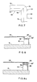
- Figure 8 shows an alternate form of the invention wherein cap 68' is generally L-shaped and includes a foot portion 80 which is flat for securing to top edge 62 of undulated strip 60, as by weld means.
- Leg 82 of cap 68' projects from the undulated strip and defines an elevated land 84 for securing the tension foil shadow mask thereto.
- land 84 is offset or extends along the inside of the support structure nearest the centrally disposed phosphor screen so that the outside corners of the composite support structure surrounding the screen can be chamfered or rounded, similar to the illustration of Figure 7, without disturbing the weld means at the inside corners of the support structure.
- Figure 8a shows another alternate form of the invention wherein a cap 68'' adopts a generally rectangular block format (in cross-section) having a lower flat surface 86 which is secured to top edge 62 of undulated strip 60.
- Cap 68'' further comprises an extended land portion 88 to which the perimeter of tension mask is secured, preferably by weld means.
- the extended land area 88 atop cap 68'' insures that adequate space is available to permit a tool to engage and hold the mask permieter in place on the land while readily permitting the weld means access to the portion of the mask adjacent the tool.
- FIG. 11 A further embodiment of the invention is shown in Figures 11, 12 & 13 wherein a shadow mask support structure 134 of this invention is formed from a strip of conductive metal so as to provide an upper planar portion or ridge 160 for securing the shadow mask 35 to the support structure.
- a plurality of legs 162a and 162b depend from the ridge to facilitate securing the support structure to faceplate 16.
- the top of ridge 160 is flattened as seen in Figure 11 and legs 162a and 162b flare outwardly from both sides of the ridge to stabilize the support structure under the tension forces of the shadow mask.
- legs 162a flare in a direction away from the center axis of the tube, and legs 162b flare inwardly toward the center axis of the tube.
- Figures 12 and 13 Two versions of support structure 134 are shown in Figures 12 and 13 and differ only in the manner in which the support structure is secured to the faceplate 16. More particularly, Figures 11 and 12 show an elongated plate or strip 164 of metal which is secured to the distal ends of legs 152a and 162b This plate or strip, in turn, is secured to faceplate 16 by hardened cement 166 (Fig. 11).
- the metal strip may be secured to the inner surface of faceplate 16, for example, by a devitrifying glass frit well-known in the art, or by a cold setting cement such as a Sauereisen-type cement.
- Tension foil shadow mask 35 is welded onto the flattened top surface of ridge 160 of support structure 134.
- the metal material of plate 164 and/or support structure 134 preferably comprises a "Carpenter 27" R.T.M. chrome-iron alloy manufactured by Carpenter Technology Inc., Reading, Pa., a metal that has a coefficient of expansion that substantially matches that of the glass of faceplate 16.
- Figure 13 shows an alternative wherein the distal ends of legs 162 and 162 are partially embedded into the glass of faceplate 16, as at 168, when the glass is elevated to a temperature between its strain point and its annealing point.
- This alternative is generally designated 134'and also includes flattened ridge 160 for supporting welded-on tension foil shadow mask 135. A process for embedding the legs into the glass will be disclosed below.
- Tension foil shadow mask support structure 134'(or 135') may be provided continuous (unbroken) about the centrally disposed phosphor screen 20.
- the support structure since the support structure is simply fabricated of two (Fig. 12) or one (Fig. 13) strips of metallic material, the support structure may be disposed along four linear sides of the screen as shown in Figure 10.
- Figures 14 and 15 show an alternate form of the invention which permits shear forming of the legs from a strip blank shown in Figures 16 and 17.
- an upper planar portion or ridge 160' provides means for securing the shadow mask to the support structure 35'.
- a series of legs 162a' flare outwardly from one side of planar portion 160' and a series of legs 162b' flare outwardly from the opposite side of the planar portion, in an alternating array.
- an aperture 170 is stamped through the metal strip at the root area between adjacent legs to facilitate forming the legs by shear forming procedures as well as to permit cleaning or "trimming" of unwanted materials deposited during the screening process.
- Figures 16 and 17 show a blank strip, generally designated 172 from which support structure 35'.( Figures 14 and 15) are formed. Apertures 170 first are stamped in a linear array longitudinally of the strip parallel to its side edges. The blank then is sheared, as at 174 between apertures 170 and edge 176 of the strip, and the legs then are easily formed. As seen best in Figure 17, the opposite edge 178 is bevelled, as at 180, so that when the legs are bent out of the plane of upper planar portion 160', the edge of each leg will be parallel to the surface of faceplate 16 for securing thereto.
- Figures 18 and 19 show still a further version of the invention incorporated in a shadow mask support structure, generally designated 134''.
- This embodiment is similar to that of Figures 14-17, except that it can be seen that legs 162b'' are shorter than legs 162a'' and are disposed in the plane of upper planar portion 160'', while alternate legs 162a'' flare or angle outwardly of the planar portion, either inwardly toward screen 20 or outwardly from screen 20.
- This embodiment still provides a broadened stance for the support structure and planar portion 160''.
- Figures 22-28 show another embodiment of the tension foil shadow mask support structure 234 and Figures 25 and 28 show an alternate form of support structure 234', the only difference being the manner in which the support structure is secured to faceplate 16. Consequently, like numerals have been applied where applicable.
- tension mask support structure 234 (or 234') comprises an undulated member defining peaks 260 and valleys 262, both of which are flattened as shown best in Figures 22, 24, 25 and 26.
- the support structure is formed from an elongated strip of metal material.
- the material is a "Carpenter 27" R.T.M. chrome-iron alloy manufactured by Carpenter Technology Inc., Reading, Pa., metal which has a coefficient of expansion that substantially matches that of the glass material of faceplate 16.
- Flattened tops 263 of peaks 260 are generally coplanar, as seen best in Figure 22, to provide means for securing tension shadow mask 35 thereto, as by welding 264.
- Flattened valleys 262 have flat bottom surfaces 266 which are coplanar and provide means for securing the support structure to the inside surface of faceplate 16.
- valleys 262 of support structure 234 are secured to faceplate 16 by a hardened cement 268 (Fig. 24) which, for example, may be a devitrifying glass frit well-known in the art, or by a cold-setting cement such as a Sauereisen-type cement.
- Figs. 25 and 26 show undulated support structure 234' secured to faceplate 16 by embedding the valleys 262 of the undulated support structure partially into the glass of the faceplate when the glass is elevated to a temperature between its strainpoint and its annealing point.
- a preferred process by which such an embedding securement can be achieved will be discussed below.
- Support structure 234 (or 234') that supports the welded-on tension foil shadow mask according to the invention may comprise a continuous ring of metal, as indicated generally at 234 in Figure 20.
- the support structure can be discontinuous ("broken") or segmented, as illustrated in Figure 21 and extending linearly along all four sides of the phosphor screen for holding the shadow mask in tension on the support structure.
- the invention also involves a preferred process for securing the mask support structure such as structure 34 to the glass faceplate 24.
- a mask support structure can be installed according to the invention.
- a mask support physically penetrates the faceplate according to the invention for permanent, cementless anchoring of the structure to the faceplate, with the embedment of the structure being of such depth as to cause the structure to resist tensile forces created by the shadow mask.
- the physical penetrating of the structure to a predetermined distance is effective to place the mounting surface of the support structure a predetermined Q distance from the faceplate inner surface.
- Shadow mask support structure 334 is shown ready to be positioned with respect to the inner surface 19 of faceplate 16, and on which is deposited a centrally disposed phosphor screen 20. When in position, support structure 334 will be seen as being located on opposed sides of the screen 20.
- the support structure 34 depicted by Figure 27 may be articulated in the corners. "Articulation,” means that the structure is linked loosely at the corners; that is, it is so joined that it aids in accommodating a differential between the thermal coefficients of expansion that may exist between the metal of the support structure and the glass of the faceplate. The joining also retains the structure in a frame-like shape during the installation process.
- Figure 28 shows in greater detail a section of support structure 334 and its relationship with the faceplate 16.
- Support structure 334 is indicated as being composed of sheet metal, and is depicted as including a mounting surface 380 for receiving and securing a shadow mask (not shown) in tension.
- a base portion 382 of support structure 334 is depicted as physically penetrating a predetermined distance into the faceplate 16 for permanent, cementless anchoring of support structure 34 to faceplate 16.
- the base portion 382 of this embodiment of a support structure is shown as comprising two legs 38 and 386 indicated by the dash lines as a physically penetrating faceplate 16.
- the embedment of the support structure can be of such depth as to cause the structure to resist tensile forces created by the shadow mask, and place the mounting surface at a predetermined Q distance from the faceplate inner surface.
- the shadow mask support structure comprises a material having, according to the invention, a coefficient of thermal expansion compatible with the glass of the faceplate.
- a suitable metal is Carpenter Alloy No. 27 R.T.M. manufactured by Carpenter Technology, Inc. of Reading, Pennsylvania. Another alloy with equivalent properties provided by another manufacturer may as well be used.
- At least the base portion of a support structure may comprise a material having a coefficient of thermal expansion compatible with the glass of the faceplate, and the base portion may comprise Carpenter Alloy No, 27 R.T.M.
- the entire structure may be composed of Alloy No. 27 R.T.M, all according to the invention.
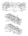
- Figure 29 is a view in perspective of a shadow mask support structure 384 resembling in some respects the support structure 34 heretofore described except that it has a foot 386 with a plurality of open-ended openings 388 therein.
- the foot 386 with its open-ended openings 88 provides cement-contactible edges for enhancing the securement of the support structure 384 to the inner surface 90 of faceplate 392, with the cement being, for example, a devitrifying glass frit.
- the foot and its open-ended openings could as well, according to the present invention, enhance the cementless anchoring of support structure 384 to faceplate 392 by physically penetrating a predetermined distance into faceplate 392.
- Figure 29A depicts in greater detail the foot 386 of support structure 384.
- the base of the support structure 384 which comprises the foot 386 in this example, is depicted as physically penetrating a predetermined distance indicated as comprising by way of example a depth greater than the thickness of the base.
- Permanent securement of the support structure 84 is accomplished by the "wetting" of the metal by the glass, causing the metal and the glass to adhere at the interface 393; both the metal of the base and the glass have to be at the proper temperatures to provide such adherence, as will be described.
- the thickness of the sheet metal material which forms support structure may be 24 mils (.06cm), by way of example.
- the depth of penetration of the foot may be in the range of 30 to 40 mils (.10cm), also by way of example. This range is by no means limiting, as the depth of penetration may also depend upon the embedding of the support structure in the inner surface of the faceplate to a depth effective to place the shadow mask mounting surface 389 of support structure 384 at a predetermined Q distance from the inner surface 390 of faceplate 392,
- the range of depth of physical penetrating may be, by way of example, from a fraction of a mil (.0024cm) to 150 (.38cm) mils or more, depending upon the type of support structure.
- FIG. 30 Another embodiment of a front assembly having a novel support structure suitable for physically penetrating a faceplate according to the invention is shown by Figure 30, which depicts a corner section of the front assembly 394 and the associated support structure 395, depicted as being in two sections in this view.
- the embodiment shown by Figure 30 represents yet another of the many available embodiments of a tensed foil shadow mask support structure that can be installed according to the invention in this example, the structure is composed primarily of a ceramic material.
- the faceplate assembly 394 comprises a faceplate 396 on the inner surface 398 of which is deposited a centrally disposed phosphor screen 400.
- the support structure consists of four ceramic rails located on opposed sides of screen 400; two of the rails--rails 402A and 402B, are depicted in this corner view.
- Rails 402A and 402B are each indicated as having caps 404A and 404B, respectively, thereon.
- Caps 404A and 404B are indicated as comprising discrete metal strips which provide mounting surfaces for receiving and securing a foil shadow mask 406 in tension.
- the base portions 408A and 408B of the rails 402A and 402B are indicated by the dash lines as physically penetrating a predetermined distance into the glass of the faceplate 391 for permanent, cementless anchoring of the support structure to the faceplate.
- the support structure has a composition adapted for adherence to the glass.
- the physical penetration of the base into the faceplate 396 may be a predetermined distance of the order of fractions of a mil (.0024cm), by way of example, for the permanent, cementless anchoring of the support structure 395 to faceplate 396.
- the depth of penetration may be much greater, with the depth depending upon the physical design of the structure, and whether it is desired that the depth of the penetrating be such as to position the mounting surfaces 404A and 404B at a predetermined distance from the inner surface 398 of faceplate 396, whereby the mounting surface(s) is positioned for receiving the foil shadow mask 406 in tension in appropriate spaced relationship to the faceplate inner surface 398.
- FIG. 31 Another embodiment of a shadow mask support structure that can be installed according to the invention is depicted in Figure 31, wherein there is shown a section of a tensed foil shadow mask support structure similar to that of Figure 13 as mounted on the inner surface of a faceplate.
- the support structure 510 is depicted as comprising a mounting surface 512 for receiving and securing a shadow mask 514 in tension.
- a plurality of legs 516A and 516B are indicated as depending from a ridge that supports the mounting surface 512 to stabilize the support structure against the tensile forces imparted by the mask 514.
- Legs 516A and 516B are depicted as flaring outwardly from the mounting surface 512 in an alternating array on opposite sides thereof.
- the base portions 518 of legs 516A and 516B are shown as physically penetrating a predetermined distance into the inner surface 520 of faceplate 522 for permanent cementless anchoring of the support structure 510 to faceplate 522 according to the present invention.
- FIG. 32 Yet another embodiment of a shadow mask support suitable for physically penetrating a predetermined distance into a faceplate according to the invention is shown by Figure 32.
- This support structure is similar to Figure 22 above and comprises an undulated member that defines peaks 526 and valleys 528, both shown as being flattened, with the flattened tops of peaks 526 providing a mounting surface for receiving and securing a foil shadow mask in tension.
- the valleys 528 or base portions, of support structure 524 are indicated as physically penetrating the glass Of the inner surface 530 of the faceplate 532.
- the support structure 524 is preferably formed from an elongated strip of metal which may comprise the aforedescribed Carpenter Alloy No. 27.
- a process according to the invention for securing a support structure for a tensed foil shadow mask to a flat glass faceplate having a centrally disposed phosphor screening area on an inner surface thereof comprises the following: providing a frame-like support structure for receiving and supporting the shadow mask in tension, the support structure having a mounting surface suitable for securing the mask thereon, and a base portion adapted for physically penetrating the faceplate; conditioning the faceplate to be physically penetrated by the support structure by heating the faceplate to a predetermined temperature in the range between the strain point temperature and the annealing point temperature of the glass; positioning the support structure on opposed sides of the screen, and locating and resting the structure against the inner surface; heating the support structure by electrical resistance to the working point temperature of the glass and pressing the structure into the glass through the inner surface, causing the base portion to penetrate to a depth effective both to permanently secure the structure to the faceplate against the tensile forces imparted by the mask and to position the mounting surface at a predetermined Q-distance from the faceplate
- the preferred temperature range of the glass of a faceplate for the installation of a support structure according to the invention is, by way of example, between 462 degrees Centigrade--the strain point of standard faceplate glass, and 503 degrees Centigrade--the annealing point of standard faceplate glass.
- the temperatures cited comprise the normal range for glass used in the faceplates of color cathode ray tube.
- a cold faceplate may be brought to the desired temperature by heating in an oven.
- the installation of the support structure according to the invention may be accomplished in the interim when the faceplate is taken from the mold and before it is put into the annealing oven. During the interim, the faceplate is allowed to cool to the desired temperature range during which a support structure can be installed.
- the recommended temperature to which the support structure should be heated is about 1000 degrees Centigrade--the working point of faceplate glass; this is equivalent to a red heat for the Carpenter No. 27 Alloy.
- Heating of the support structure, if metal, to the proper temperature is preferably by electrical resistance; also feasible are heating by induction or by means of an oven.
- the temperatures to which the support structure and the glass are heated are preferably those that will provide the necessary "wetting" of the contacting surfaces to effect proper adherence and permanent anchoring of the support structure to the faceplate.
- the base portion of a support structure can readily physically penetrate the glass of the faceplate.
- Figure 33 is a diagrammatic depiction of an apparatus suitable for the physical penetration according to the invention of a support structure into a faceplate.
- the support structure 334 shown by way of example, is the support structure shown by Figures 27 and 28.
- the structure is noted as comprising a base portion 382 having two legs 384 and 386, depicted as physically penetrating faceplate 16.
- Means for the accomplishing physical penetration is depicted schematically as comprising a metal plate 534 which, as indicated by the arrows 536, represents the physical penetrating of the base portion 382 of support structure 334 into the glass of the inner surface 19 of the faceplate 16 according to the invention.
- Shims 538 and 540 are depicted as controlling the depth of penetration of the support structure to place the mounting surface of the structure at a predetermined Q-distance from the inner surface 19 of faceplate 16.
- the positioning of the support structure with respect to its proper location on the inner surface of the faceplate may be accomplished by a suitable fixture which holds the support structure 334 during heating, and ensures that it is in proper registry when it is lowered onto the inner surface 19 of faceplate 16.
- the construction of such a fixture for all configurations of support structures is well within the capabilities of those skilled in the art of cathode ray tube manufacture.
Landscapes
- Electrodes For Cathode-Ray Tubes (AREA)
Abstract
Description
- This invention generally relates to color cathode ray picture tubes and, specifically, to a novel front assembly for color tubes that have a tension foil shadow mask. The invention also relates to a process of securing a support structure to a glass faceplate for use in the manufacture of such tubes. The invention is useful in color tubes of various types including those used in home entertainment television receivers, and those used in medium-resolution and high-resolution tubes intended for color monitors.
- The use of the tension foil mask and a flat faceplate provides many advantages and benefits in comparison with the conventional curved or domed shadow mask. Chief among these is a greater power-handling capability which makes possible as much as a three-fold increase in brightness. The conventional curved shadow mask, which is not under tension, tends to "dome" in high-brightness picture areas where the intensity of electron bombardment is greatest. Color impurities result as the mask moves closer to the faceplate. Being under high tension, the tension foil mask does not dome or otherwise move in relation to the faceplate. Therefore, it has greater brightness potential while maintaining color purity.
- The tension foil shadow mask is a part of the cathode ray tube front assembly, and is located in close adjacency to the faceplate. The front assembly comprises the faceplate with its deposits of light-emitting phosphors, a shadow mask, and support means for the mask. As used herein, the term "shadow mask" means an apertured metallic foil which may have a thickness, by way of example, of about one mil or less. The mask must be supported in high tension a predetermined distance from the inner surface of the cathode ray tube faceplate. This distance is known as the "Q-distance." The high tension may be in the range of 20 to 40 kpsi (1406 kolograms/sq.cm to 2812 kilograms/sq.cm). As is well known in the art, the shadow mask acts as a color-selection electrode, or parallax barrier, which ensures that each of the three color-beams lands only on its assigned phosphor deposits.
- The requirements for the support means for the shadow mask are stringent. As has been noted, the shadow mask must be mounted under high tension. The mask support means must be of high strength so that the mask is held immovable. An inward movement of the mask of as little as one-tenth of a mil (.00025 cm) is significant in that guard band may be expended. Also, the shadow mask support means must be of such configuration and material composition as to be compatible with the means to which it is attached. As an example, if the support means is attached to glass such as the inner surface of the faceplate, the support means must have about the same thermal coefficient of expansion as that of the glass. The support means must provide a suitable surface for mounting the mask. Also, the support means must be of a composition such that the mask can be welded onto it by electrical resistance welding or by laser welding. The support surface preferably is of such flatness that no voids can exist between the metal of the mask and the support structure to prevent the intimate metal-to-metal contact required for proper welding.
- Means for securing the shadow mask support to the inner surface of the faceplate may comprise a cement in the form of a devitrifying glass frit. While satisfactory in the main, cement of this type has significant disadvantages in that it is difficult to handle and apply in production, and it tends to create "pockets" in which screening fluids may lodge and be released later as contaminants. Also, the composition of the frit itself is subject to chemical breakdown when exposed to strong chemicals normally applied during the photoscreening process, and the byproducts of the breakdown may contaminate and poison the tube inner environment.
- A tension mask registration and supporting system is disclosed by Strauss in U.S. Patent No. US-A-4,547,696 of common ownership herewith. A frame dimensioned to enclose the screen comprises first and second space-apart surfaces. A tensed foil shadow mask has a peripheral portion bonded to a second surface of the frame. The frame is registered with the faceplate by ball-and-groove indexing means. The shadow mask is sandwiched between the frame and a stabilizing or stiffening member. When the system is assembled, the frame is located between the sealing lands of the faceplate and a funnel, with the stiffening member projecting from the frame into the funnel. While the system is feasible and provides an effective means for holding a mask under high tension and rigidly planoparallel with a flat faceplate, weight is added to the cathode ray tube, and additional process steps are required in manufacture.
- There exists in the marketplace today a color tube that utilizes a tensed shadow mask. The mask is understood to be placed under high tension by purely mechanical means. Specifically, a very heavy mask support frame is compressed prior to and during affixation of the mask to it. Upon release of the frame, restorative forces in the frame cause the mask to be placed under high residual tension. During normal tube operation, electron beam bombardment causes the mask to heat up and the mask tension to be reduced. An upper limit is placed on the intensity of the electron beams that may be used to bombard the screen without causing the mask to relax completely and lose its color selection capability. The upper limit has been found to be below that required to produce color pictures of the same brightness as are produced in tubes having non-tensed shadow masks. For descriptions of examples of this type of tube, see U.S. Patent No. US-A-3683,063.
- Other prior art include: U.S. Patent Nos. US-A-4,087,717; US-A-4,045,701; US-A-4,100.451; US-A-2,625,734; US-A-3,727,087; US-A-4,069,567; US-A-3,894,321; US-A-3,284,655; US-A-3,303,536; US-A-2,905,845; and US-A-2,842,696. Reference is also made to a journal article: "The CBS Colortron: A color picture tube of advanced design." Fyler et al. Proc. of the IRE, Jan. 1954. Dec. class R583.6; and a digest article: "A High-Brightness Shadow-Mask Color CRT for Cockpit Displays." Robinder et al. Society for Information Display, 1983. Document US-A-3 894 321 shows in the Figures 2 and 2A a front assembly for a color-CRT having a
mask 12 sealed to the top surface of aninner ledge 28 near the periphery of the faceplate. The ledge can form a continuous path around the panel - see Figure 2A. - It is known in the cathode ray tube manufacturing art to install metal studs or pins in the skirt of a tube faceplate by forcing them into the softened glass of the skirt. The studs serve as suspension points for the bimetallic springs, usually three in number, that support the curved shadow mask suspended in association with the curved faceplate of the conventional cathode ray tube. U.S. Patent No. 3,695, 860 discloses automated apparatus for embedding metal pins in a glass panel and comprises means for holding the pins in proper registry with the inside of the faceplate skirt, and means for flame-heating the embedding tips of the pins and, flame-heating the area of the skirt where the pins are to be installed. The areas of pin embedment in the skirt are heated to about 1150 degrees C., and the pins to about 1,050 degrees C. The pins, which are held in pin chucks, are then forced into the glass of the skirt by a ring-cam mechanism.
- U.S. Patent No. US-A-3,890,526 discloses a faceplate mounting structure for a curved color selection electrode for a cathode ray tube having a curved faceplate. The mounting structure includes four sheet-metal studs comprising part of an electrode suspension device. The studs are embedded in the curved faceplate by a hot sealing operation. The disclosure includes a description of machine for installing the studs, which provides means for flame-heating the studs, and simultaneously the areas of the faceplate which receive them, after which the studs are automatically pressed into the glass.
- A glass-to-metal ceramic seal or bond is described by Daniel I. Pomerantz of the Mallory Laboratory for Physical Science, Burlington, Mass. A flat piece of glass is placed in contact with a flat piece of metal. The two pieces are heated to a temperature about 250 degrees C. below the softening point of the glass. A direct current is applied across the two parts to form what is in effect a capacitor, with the metal part polarized positive. The result is said to be a bonding of the two parts. No commercial application of this process to the cathode ray tube construction art is presently known. (Source: "Sealed with a Kilovolt," an article by David H. Surgan. The Electronic Engineer, September 1958. Pp. 16-17.
- In general the invention aims to provide an improved front assembly for tension foil shadow mask tubes.
- The present invention therefore provides a front assembly for a color cathode ray tube including a faceplate having on its inner surface a centrally disposed phosphor screen, said assembly including a shadow mask support structure having an undulated cross-section and substantially surrounding the phosphor screen for supporting the shadow mask in tension upon said undulated structure, and means for securing said undulated structure to the faceplate.
- The improved shadow mask support structure of the invention has the advantage of being low in cost and light in weight. Further, the support structure simplifies manufacture and lowers manufacturing costs.
- It is a further aim of the invention to provide an improved faceplate assembly for a color cathode ray tube having a tensed foil shadow mask and a substantially flat faceplate as well as to provide a simplified process for attaching a tensed foil shadow mask support to a substantially flat faceplate.
- The present invention therefore provides in the
independent claims - The present invention also relates in
claim 19 to a process of securing a support structure for a tensed foil shadow mask to a glass faceplate having a centrally disposed phosphor screening area on an inner surface thereof, said process including the steps of providing a frame-like support structure for receiving and supporting said shadow mask in tension, said support structure having a mounting surface suitable for securing said mask thereon, and a base portion adapted for physically penetrating said faceplate; providing a faceplate at least said surface of which is heated to a predetermined temperature at which it is conditioned to be penetrated by said support structure; pressing said structure into said faceplate through said inner surface on opposed sides of said screen, causing said base portion to penetrate to a depth effective both to secure said structure to said faceplate against the tensile forces imparted by said mask, and to position said mounting surface at a predetermined distance from said faceplate inner surface, whereby said mounting surface is positioned for receiving said foil shadow mask in tension in appropriate spaced relationship to said faceplate inner surface; and mounting said foil mask in tension on said mounting surface after the disposition of the phosphor screen on said inner surface. - The dependent claims describe particular embodiments of the invention.
- One advantage of the improved faceplate assembly is that it assures that a tensed foil shadow mask is more securely mounted on the faceplate. In addition, this improved assembly provides means, for permanently mounting a support structure for a shadow mask on a faceplate without the need for a special cement.
- The improved process of the invention secures a tensed foil shadow mask support to the faceplate inner surface in such manner as to insure that no pockets for the lodgment of contaminants during manufacture.
- Further features and advantages of the invention will be more apparent from the following description of preferred embodiments of the invention taken together with the accompanying drawings wherein:
- Figure 1 is a cut-away perspective view of a cabinet housing a cathode ray tube having a front assembly according to the invention;
- Figure 2 is a cut-away side perspective view of the color cathode ray tube of Figure 1, illustrating the location of a shadow mask support structure incorporating the concepts of the invention;
- Figure 3 is a plan view showing the relationship of the shadow mask support structure to the inner surface of the cathode ray tube faceplate shown in Figure 2;
- Figure 4 is a broken section, on an enlarged scale, taken through the front assembly generally on the axis of the cathode ray tube;
- Figure 5 is a fragmented section through the front assembly illustrating, on an enlarged scale, one end of the shadow mask support structure of the invention;
- Figure 6 is a fragmented, exploded perspective view, of the undulated member and cap of the shadow mask support structure;
- Figure 7 is a top plan view of the mating corner of a pair of support structures;
- Figure 8 is a broken section, similar to that of Figure 5, of an alternate form of the invention; and
- Figure 8a is also a broken section, similar to that of Figure 8, showing another form of the invention.
- Figure 9 is a cut-away side perspective view of a further embodiment of the invention included in a color cathode ray tube like that shown in Figure 1 illustrating the location of a modified shadow mask support structure incorporating the concepts of the invention;
- Figure 10 is a plan view showing the relationship of the modified shadow mask support structure to the inner surface of the cathode ray tube faceplate shown in Figure 9;
- Figure 11 is a broken section, on an enlarged scale, taken through the front assembly generally on the axis of the cathode ray tube of Figure 9;
- Figure 12 is a fragmented perspective view illustrating one aspect of the modified shadow mask support structure of Figure 9;
- Figure 13 is a fragmented perspective view of another aspect of the modified shadow mask support structure of Figure 9;
- Figure 14 is a fragmented perspective view of a further aspect of the modified shadow mask support structure of Figure 9;
- Figure 15 is an end view of the support structure of Figure 14;
- Figure 16 is a plan view of a blank from which the support structure of Figures 14 and 15 is stamped and formed;
- Figure 17 is an end view of the blank of Figure 16;
- Figure 18 is a fragmented perspective view of still another aspect of the modified shadow mask support structure of Figure 9;
- Figure 19 is an end view of the support structure of Figure 17;
- Figure 20 is a cut-away side perspective view of another embodiment of the invention included in a color cathode ray tube like that of Figure 1 illustrating the location of further modified shadow mask support structure incorporating the concepts of the invention;
- Figure 21 is a plan view showing the relationship of the further modified shadow mask support structure to the inner surface of the cathode ray tube faceplate shown in Figure 20;
- Figure 22 is a fragmented elevational view of one form of the further modified support structure of Figure 20 mounted on a section of the faceplate, with the tension mask welded thereto;
- Figure 23 is a fragmented plan view of the support structure of Figure 22 , with the tension mask removed to facilitate the illustration;
- Figure 24 is a fragmented section taken generally along line 24-24 of Figure 22;
- Figure 25 is a fragmented perspective view of the support structure of Figure 22, as secured to the faceplate in an alternate manner;
- Figure 26 is an axial section through the front assembly of the color cathode ray tube of Figure 20;
- Figure 27 is a view in perspective showing a flat, or substantially flat faceplate, with a frame-like tensed-foil shadow mask support structure indicated diagrammatically as being in position for placement on the faceplate inner surface;
- Figure 28 is a perspective view showing in enlarged detail a section of the shadow mask support structure of Figure 27 depicted as being secured according to the inventive process to the inner surface of the faceplate;
- Figure 29 is a perspective view of a section of a faceplate and a different shadow mask support structure showing the securement of the support structure to the inner surface of a faceplate according to the process of the invention; inset Figure 29A depicts the encircled section of Figure 29 in enlarged detail;
- Figure 30 is a perspective view of a corner section of another type of shadow mask support structure showing the securement of this type of support structure to the inner surface of a faceplate according to the process of the invention;
- Figure 31 is a perspective view of a section of a faceplate showing a shadow mask support structure like that in Figure 12 as secured to the inner surface of a faceplate according to the process of the invention;
- Figure 32 is a perspective of a section of a faceplate in which a sahdow mask support structure according to the Figure 22 herein is shown as secured to the inner surface of a faceplate according to the process of the invention; and
- Figure 33 is a view in section and in elevation depicting an apparatus used in the process according to the invention for installing a shadow mask support structure.
- Figure 1 depicts a video monitor, generally designated 10, that houses a color cathode ray tube, generally designated 12, having a novel front assembly according to the invention. The monitor-associated tube is notable for the flat imaging area 14 that makes possible the display of images in undistorted form. Imaging area 14 also offers a more efficient use of screen area as the corners are relatively square in comparison with the more rounded corners of the conventional cathode ray tube.
- With reference also to Figures 2, 3 and 4, a front assembly 15 (Fig. 4) for a high-resolution color cathode ray tube is depicted, the general scope of which is indicated by the bracket.
Front assembly 15 includes aglass faceplate 16 noted as being flat, or alternately, "substantially" flat in that it may have finite horizontal and vertical radii.Faceplate 16, depicted in this embodiment of the invention as being planar and flangeless, has on its inner surface a centrally disposedphosphor target area 18, on which is deposited an electricallyconductive film 19. Phosphor target area18 andconductive film 19 comprise the electron beam target area, commonly termed a "screen," generally designated 20, which serves, during manufacture, for receiving a uniform coat of phosphor slurry.Conductive film 19, which is deposited on the phosphor deposits in a final step, typically consists of a very thin, light-reflective, electron-pervious film of aluminum. -
Screen 20 is surrounded by aperipheral sealing area 21 adapted to be mated with afunnel 22. Sealingarea 21 is represented as having three substantially radially oriented first indexing V-grooves therein, only twogrooves faceplate 16; that is, at 120-degree intervals.Indexing grooves peripheral sealing area 21 equidistantly from indexingelements indexing faceplate 16 in conjunction with a mating envelope member, as will be shown. -
Funnel 22 has afunnel sealing area 28 with second indexing elements orgrooves 30A and 30B therein in like orientation, and depicted in Figure 4 in facing adjacency with thefirst indexing elements elements faceplate 16 and thefunnel 22. The first indexing elements together with the ball means are also utilized as indexing means during the photoscreening of the phosphor deposits on the faceplate. -
Front assembly 15 according to the invention includes a tension foil mask support structure, generally designated 34, secured to the inner surface offaceplate 16 betweenscreen 20 andperipheral sealing area 21 and enclosing thephosphor target 18. The support structure provides for supporting a tension foil shadow mask 35 a predetermined "Q-distance" from the inner surface offaceplate 16. The predetermined distance may comprise the "Q-distance" 36, as indicated by the associated arrow in Figure 4. The mask, indicated as being planar, is depicted as being stretched in all directions in the plane of the mask. - As seen in Figure 2, a
neck 37 extending fromfunnel 22 is represented as housing anelectron gun 38 which is indicated as emitting threeelectron beams phosphor target 18, noted as comprising colored-light emitting phosphor deposits overlayed with aconductive film 19.Beams shadow mask 35. -
Funnel 22 is indicated as having an internal electricallyconductive funnel coating 45 adapted to receive a high electrical potential. The potential is depicted as being applied through ananode button 46 attached to aconductor 47 which conducts a high electrical potential to theanode button 46 through the wall offunnel 22. The source of the potential is a high-voltage power supply (not shown). The potential may be, for example, in the range of 18 to 26 kilovolts in the illustrated monitor application. Means for providing an electrical connection between the electricallyconductive support structure 34 and funnelcoating 45 may comprise spring means "S" (depicted in Figure 2). - A magnetically permeable internal
magnetic shield 48 is shown as being attached to supportstructure 34.Shield 48 extends into funnel 22 apredetermined distance 49 which is calculated so that there is no interference with the excursion of the electron beams 40, 42 and 44, yet maximum shielding is provided. - A
yoke 50 is shown as encirclingtube 12 in the region of the junction betweenfunnel 22 andneck 37.Yoke 50 provides for the electromagnetic scanning ofbeams screen 20. The center axia 52 oftube 12 is indicated by the broken line. - Referring to Figures 5 and 6 in conjunction with the previously described figures, particularly Figure 4, the shadow
mask support structure 34 of this invention is formed from a strip of conductive metal, generally designated 60, which is in an undulated configuration defining a topsinuous edge 62 and a bottomsinuous edge 64.Bottom edge 64 provides means for securing the support structure tofaceplate 16.Top edge 62 provides means for securingshadow mask 35 to the support structure. The undulated strip has a generally uniform width (i.e., height in a direction between the faceplate and the shadow mask) whereby topsinuous edge 62 is disposed in a plane generally parallel to the faceplate. The sides of the undulated strip, as at 66a and 66b are flattened wherebysides 66a are disposed in a common plane andsides 66b are disposed in a common plane, the planes being generally parallel in a direction perpendicular to the faceplate and the shadow mask. However, it is to be appreciated that the undulated strip can adopt a more serpentine configuration so that a plan view of the strip would exhibit, for example, a "sine-wave" or a "triangular-wave", etc. profile, as contrasted to the "square-wave" depiction in Figure 6. - As noted above, top
sinuous edge 62 provides the means for securingshadow mask 35 to supportstructure 34. Therefore, in accordance with a basic practice of the invention,mask 35 can be secured, as by welding, directly to edge 62. - In a particular embodiment of the invention, Figure 6, a cap, generally designated 68, is positioned over the top of undulated
strip 60, i.e., over topsinuous edge 62. Like undulatedstrip 60,cap 68 is elongated and extends along the sides ofphosphor screen 20. -
Cap 68 is generally U-shaped withleg portions 70a and70b overlying sides strip 60.Cap 68 is fabricated of metal material and is secured to undulatedstrip 60 by weld means betweenleg portions 70a, 70b of the cap andsides - The top of
cap 68 has a somewhat "stepped" configuration to include a generallyflat portion 72 and anelevated land portion 74.Flat portion 72 rests on topsinuous edge 62 of undulatedstrip 60, as best seen in Figures 4 and 5.Elevated land portion 74 provides a generally planar ridge for securing the shadow mask thereto, as by weld means. - The metal material of undulated
strip 60 andcap 68 preferably comprises a "Carpenter #27 R.T.M. chrome-iron alloy that has a coefficient of expansion that substantially matches that of the glass offaceplate 16. - Tension foil shadow
mask support structure 34 may be disposed along four linear sides of the centrally disposedphosphor screen 20, since the support structure is simply fabricated of two or one strips of metallic material. On the other hand, the support structure may be provided substantially continuous (unbroken) about the centrally disposed phosphor screen. To this end, it can be seen in Figures 4-6 thatelevated land portion 74 is offset or located along the inside ofcap 68, i.e., along the inside of the topsinuous edge 62 nearest the centrally disposed phosphor screen. The advantages of such an inward location are illustrated in Figure 7 where it can be seen that at the mating of the linear sections of the support structure, i.e., at the corner areas of the phosphor screen, the outside corners are rounded, as at 76. The mating inside corners of the adjacent caps and/or the adjacent end edges of the undulated strips can be secured, as by welding at 78. In this manner, rounding the outer corners of the shadow mask support structure does not interfere with the weld securement. Figure 2 shows the shadow mask support structure continuously surrounding the centrally disposedphosphor screen 20. - Figure 8 shows an alternate form of the invention wherein cap 68' is generally L-shaped and includes a
foot portion 80 which is flat for securing totop edge 62 of undulatedstrip 60, as by weld means. Leg 82 of cap 68' projects from the undulated strip and defines anelevated land 84 for securing the tension foil shadow mask thereto. Again, it can be seen thatland 84 is offset or extends along the inside of the support structure nearest the centrally disposed phosphor screen so that the outside corners of the composite support structure surrounding the screen can be chamfered or rounded, similar to the illustration of Figure 7, without disturbing the weld means at the inside corners of the support structure. - Figure 8a shows another alternate form of the invention wherein a cap 68'' adopts a generally rectangular block format (in cross-section) having a lower
flat surface 86 which is secured totop edge 62 of undulatedstrip 60. Cap 68'' further comprises anextended land portion 88 to which the perimeter of tension mask is secured, preferably by weld means. Theextended land area 88 atop cap 68'' insures that adequate space is available to permit a tool to engage and hold the mask permieter in place on the land while readily permitting the weld means access to the portion of the mask adjacent the tool. - A further embodiment of the invention is shown in Figures 11, 12 & 13 wherein a shadow
mask support structure 134 of this invention is formed from a strip of conductive metal so as to provide an upper planar portion orridge 160 for securing theshadow mask 35 to the support structure. A plurality oflegs faceplate 16. The top ofridge 160 is flattened as seen in Figure 11 andlegs legs 162a flare in a direction away from the center axis of the tube, andlegs 162b flare inwardly toward the center axis of the tube. - Two versions of
support structure 134 are shown in Figures 12 and 13 and differ only in the manner in which the support structure is secured to thefaceplate 16. More particularly, Figures 11 and 12 show an elongated plate or strip 164 of metal which is secured to the distal ends oflegs 152a and 162b This plate or strip, in turn, is secured to faceplate 16 by hardened cement 166 (Fig. 11). The metal strip may be secured to the inner surface offaceplate 16, for example, by a devitrifying glass frit well-known in the art, or by a cold setting cement such as a Sauereisen-type cement. -
Legs metal support structure 134 may be secured to plate 164 by welding. Tensionfoil shadow mask 35, in turn, is welded onto the flattened top surface ofridge 160 ofsupport structure 134. - The metal material of
plate 164 and/orsupport structure 134 preferably comprises a "Carpenter 27" R.T.M. chrome-iron alloy manufactured by Carpenter Technology Inc., Reading, Pa., a metal that has a coefficient of expansion that substantially matches that of the glass offaceplate 16. - Figure 13 shows an alternative wherein the distal ends of legs 162 and 162 are partially embedded into the glass of
faceplate 16, as at 168, when the glass is elevated to a temperature between its strain point and its annealing point. This alternative is generally designated 134'and also includes flattenedridge 160 for supporting welded-on tensionfoil shadow mask 135. A process for embedding the legs into the glass will be disclosed below. - Tension foil shadow mask support structure 134'(or 135') may be provided continuous (unbroken) about the centrally disposed
phosphor screen 20. On the other hand, since the support structure is simply fabricated of two (Fig. 12) or one (Fig. 13) strips of metallic material, the support structure may be disposed along four linear sides of the screen as shown in Figure 10. - Figures 14 and 15 show an alternate form of the invention which permits shear forming of the legs from a strip blank shown in Figures 16 and 17. As with the embodiments of Figures 12 and 13 an upper planar portion or ridge 160' provides means for securing the shadow mask to the support structure 35'. A series of
legs 162a' flare outwardly from one side of planar portion 160' and a series oflegs 162b' flare outwardly from the opposite side of the planar portion, in an alternating array. In this version, anaperture 170 is stamped through the metal strip at the root area between adjacent legs to facilitate forming the legs by shear forming procedures as well as to permit cleaning or "trimming" of unwanted materials deposited during the screening process. - More particularly, Figures 16 and 17 show a blank strip, generally designated 172 from which support
structure 35'.(Figures 14 and 15) are formed.Apertures 170 first are stamped in a linear array longitudinally of the strip parallel to its side edges. The blank then is sheared, as at 174 betweenapertures 170 and edge 176 of the strip, and the legs then are easily formed. As seen best in Figure 17, theopposite edge 178 is bevelled, as at 180, so that when the legs are bent out of the plane of upper planar portion 160', the edge of each leg will be parallel to the surface offaceplate 16 for securing thereto. - Figures 18 and 19 show still a further version of the invention incorporated in a shadow mask support structure, generally designated 134''. This embodiment is similar to that of Figures 14-17, except that it can be seen that
legs 162b'' are shorter thanlegs 162a'' and are disposed in the plane of upper planar portion 160'', whilealternate legs 162a'' flare or angle outwardly of the planar portion, either inwardly towardscreen 20 or outwardly fromscreen 20. This embodiment still provides a broadened stance for the support structure and planar portion 160''. - Figures 22-28 show another embodiment of the tension foil shadow
mask support structure 234 and Figures 25 and 28 show an alternate form of support structure 234', the only difference being the manner in which the support structure is secured tofaceplate 16. Consequently, like numerals have been applied where applicable. - More particularly, tension mask support structure 234 (or 234') comprises an undulated
member defining peaks 260 andvalleys 262, both of which are flattened as shown best in Figures 22, 24, 25 and 26. The support structure is formed from an elongated strip of metal material. Preferably, the material is a "Carpenter 27" R.T.M. chrome-iron alloy manufactured by Carpenter Technology Inc., Reading, Pa., metal which has a coefficient of expansion that substantially matches that of the glass material offaceplate 16. - Flattened tops 263 of
peaks 260 are generally coplanar, as seen best in Figure 22, to provide means for securingtension shadow mask 35 thereto, as by welding 264. - Flattened
valleys 262 have flat bottom surfaces 266 which are coplanar and provide means for securing the support structure to the inside surface offaceplate 16. In the embodiment shown in Figures 22-24valleys 262 ofsupport structure 234 are secured to faceplate 16 by a hardened cement 268 (Fig. 24) which, for example, may be a devitrifying glass frit well-known in the art, or by a cold-setting cement such as a Sauereisen-type cement. - Figs. 25 and 26 show undulated support structure 234' secured to faceplate 16 by embedding the
valleys 262 of the undulated support structure partially into the glass of the faceplate when the glass is elevated to a temperature between its strainpoint and its annealing point. A preferred process by which such an embedding securement can be achieved will be discussed below. - Support structure 234 (or 234') that supports the welded-on tension foil shadow mask according to the invention may comprise a continuous ring of metal, as indicated generally at 234 in Figure 20. On the other hand, with the support structure being simply and inexpensively manufactured in an undulated configuration from a strip of metal material, the support structure can be discontinuous ("broken") or segmented, as illustrated in Figure 21 and extending linearly along all four sides of the phosphor screen for holding the shadow mask in tension on the support structure.
- As noted above, the invention also involves a preferred process for securing the mask support structure such as
structure 34 to theglass faceplate 24. As will be shown below, various configurations of a mask support structure can be installed according to the invention. Whatever its form, a mask support physically penetrates the faceplate according to the invention for permanent, cementless anchoring of the structure to the faceplate, with the embedment of the structure being of such depth as to cause the structure to resist tensile forces created by the shadow mask. Also, the physical penetrating of the structure to a predetermined distance is effective to place the mounting surface of the support structure a predetermined Q distance from the faceplate inner surface. - With reference to Figure 27, the
faceplate 16 andmask support structure 334 of a faceplate assembly similar to that of Figures 2 and 3 are depicted prior to being assembled. Shadowmask support structure 334 is shown ready to be positioned with respect to theinner surface 19 offaceplate 16, and on which is deposited a centrally disposedphosphor screen 20. When in position,support structure 334 will be seen as being located on opposed sides of thescreen 20. - The
support structure 34 depicted by Figure 27 may be articulated in the corners. "Articulation," means that the structure is linked loosely at the corners; that is, it is so joined that it aids in accommodating a differential between the thermal coefficients of expansion that may exist between the metal of the support structure and the glass of the faceplate. The joining also retains the structure in a frame-like shape during the installation process. - Figure 28 shows in greater detail a section of
support structure 334 and its relationship with thefaceplate 16.Support structure 334 is indicated as being composed of sheet metal, and is depicted as including a mountingsurface 380 for receiving and securing a shadow mask (not shown) in tension. Abase portion 382 ofsupport structure 334 is depicted as physically penetrating a predetermined distance into thefaceplate 16 for permanent, cementless anchoring ofsupport structure 34 tofaceplate 16. Thebase portion 382 of this embodiment of a support structure is shown as comprising twolegs faceplate 16. The embedment of the support structure can be of such depth as to cause the structure to resist tensile forces created by the shadow mask, and place the mounting surface at a predetermined Q distance from the faceplate inner surface. - The shadow mask support structure, indicated symbolically as being a metal, comprises a material having, according to the invention, a coefficient of thermal expansion compatible with the glass of the faceplate. A suitable metal is Carpenter Alloy No. 27 R.T.M. manufactured by Carpenter Technology, Inc. of Reading, Pennsylvania. Another alloy with equivalent properties provided by another manufacturer may as well be used. At least the base portion of a support structure may comprise a material having a coefficient of thermal expansion compatible with the glass of the faceplate, and the base portion may comprise Carpenter Alloy No, 27 R.T.M. Alternatively, the entire structure may be composed of Alloy No. 27 R.T.M, all according to the invention.
- Figure 29 is a view in perspective of a shadow
mask support structure 384 resembling in some respects thesupport structure 34 heretofore described except that it has afoot 386 with a plurality of open-endedopenings 388 therein. Thefoot 386 with its open-endedopenings 88 provides cement-contactible edges for enhancing the securement of thesupport structure 384 to the inner surface 90 offaceplate 392, with the cement being, for example, a devitrifying glass frit. The foot and its open-ended openings could as well, according to the present invention, enhance the cementless anchoring ofsupport structure 384 tofaceplate 392 by physically penetrating a predetermined distance intofaceplate 392. - Figure 29A depicts in greater detail the
foot 386 ofsupport structure 384. The base of thesupport structure 384, which comprises thefoot 386 in this example, is depicted as physically penetrating a predetermined distance indicated as comprising by way of example a depth greater than the thickness of the base. Permanent securement of thesupport structure 84 is accomplished by the "wetting" of the metal by the glass, causing the metal and the glass to adhere at theinterface 393; both the metal of the base and the glass have to be at the proper temperatures to provide such adherence, as will be described. The thickness of the sheet metal material which forms support structure may be 24 mils (.06cm), by way of example. For material of this thickness, the depth of penetration of the foot may be in the range of 30 to 40 mils (.10cm), also by way of example. This range is by no means limiting, as the depth of penetration may also depend upon the embedding of the support structure in the inner surface of the faceplate to a depth effective to place the shadow mask mounting surface 389 ofsupport structure 384 at a predetermined Q distance from theinner surface 390 offaceplate 392, The range of depth of physical penetrating may be, by way of example, from a fraction of a mil (.0024cm) to 150 (.38cm) mils or more, depending upon the type of support structure. - Another embodiment of a front assembly having a novel support structure suitable for physically penetrating a faceplate according to the invention is shown by Figure 30, which depicts a corner section of the
front assembly 394 and the associatedsupport structure 395, depicted as being in two sections in this view. The embodiment shown by Figure 30 represents yet another of the many available embodiments of a tensed foil shadow mask support structure that can be installed according to the invention in this example, the structure is composed primarily of a ceramic material. Thefaceplate assembly 394 comprises afaceplate 396 on theinner surface 398 of which is deposited a centrally disposedphosphor screen 400. The support structure consists of four ceramic rails located on opposed sides ofscreen 400; two of the rails--rails 402A and 402B, are depicted in this corner view.Rails caps Caps foil shadow mask 406 in tension. Thebase portions rails faceplate 396 may be a predetermined distance of the order of fractions of a mil (.0024cm), by way of example, for the permanent, cementless anchoring of thesupport structure 395 tofaceplate 396. In other embodiments, the depth of penetration may be much greater, with the depth depending upon the physical design of the structure, and whether it is desired that the depth of the penetrating be such as to position the mountingsurfaces inner surface 398 offaceplate 396, whereby the mounting surface(s) is positioned for receiving thefoil shadow mask 406 in tension in appropriate spaced relationship to the faceplateinner surface 398. - Another embodiment of a shadow mask support structure that can be installed according to the invention is depicted in Figure 31, wherein there is shown a section of a tensed foil shadow mask support structure similar to that of Figure 13 as mounted on the inner surface of a faceplate. The
support structure 510 is depicted as comprising a mountingsurface 512 for receiving and securing ashadow mask 514 in tension. A plurality oflegs surface 512 to stabilize the support structure against the tensile forces imparted by themask 514.Legs surface 512 in an alternating array on opposite sides thereof. Thebase portions 518 oflegs inner surface 520 offaceplate 522 for permanent cementless anchoring of thesupport structure 510 tofaceplate 522 according to the present invention. - Yet another embodiment of a shadow mask support suitable for physically penetrating a predetermined distance into a faceplate according to the invention is shown by Figure 32. This support structure is similar to Figure 22 above and comprises an undulated member that defines
peaks 526 andvalleys 528, both shown as being flattened, with the flattened tops ofpeaks 526 providing a mounting surface for receiving and securing a foil shadow mask in tension. Thevalleys 528 or base portions, ofsupport structure 524 are indicated as physically penetrating the glass Of theinner surface 530 of thefaceplate 532. Thesupport structure 524 is preferably formed from an elongated strip of metal which may comprise the aforedescribed Carpenter Alloy No. 27. - A process according to the invention for securing a support structure for a tensed foil shadow mask to a flat glass faceplate having a centrally disposed phosphor screening area on an inner surface thereof comprises the following: providing a frame-like support structure for receiving and supporting the shadow mask in tension, the support structure having a mounting surface suitable for securing the mask thereon, and a base portion adapted for physically penetrating the faceplate; conditioning the faceplate to be physically penetrated by the support structure by heating the faceplate to a predetermined temperature in the range between the strain point temperature and the annealing point temperature of the glass; positioning the support structure on opposed sides of the screen, and locating and resting the structure against the inner surface; heating the support structure by electrical resistance to the working point temperature of the glass and pressing the structure into the glass through the inner surface, causing the base portion to penetrate to a depth effective both to permanently secure the structure to the faceplate against the tensile forces imparted by the mask and to position the mounting surface at a predetermined Q-distance from the faceplate inner surface. As a result, the mounting surface is positioned for receiving the foil shadow mask in tension in appropriate spaced relationship to the faceplate inner surface, and for mounting the foil mask in tension on the mounting surface after the disposition of the phosphor screen on the inner surface.
- Concerning the "conditioning" of the faceplate, the preferred temperature range of the glass of a faceplate for the installation of a support structure according to the invention is, by way of example, between 462 degrees Centigrade--the strain point of standard faceplate glass, and 503 degrees Centigrade--the annealing point of standard faceplate glass. The temperatures cited comprise the normal range for glass used in the faceplates of color cathode ray tube. A cold faceplate may be brought to the desired temperature by heating in an oven. Alternately, and more cost effectively, the installation of the support structure according to the invention may be accomplished in the interim when the faceplate is taken from the mold and before it is put into the annealing oven. During the interim, the faceplate is allowed to cool to the desired temperature range during which a support structure can be installed.
- With regard to the temperature of the support structure that is pressed into the glass of the inner surface according to the inventive process, if Carpenter Alloy No. 27 is used, the recommended temperature to which the support structure should be heated is about 1000 degrees Centigrade--the working point of faceplate glass; this is equivalent to a red heat for the Carpenter No. 27 Alloy. Heating of the support structure, if metal, to the proper temperature is preferably by electrical resistance; also feasible are heating by induction or by means of an oven. The temperatures to which the support structure and the glass are heated are preferably those that will provide the necessary "wetting" of the contacting surfaces to effect proper adherence and permanent anchoring of the support structure to the faceplate. In addition, at the temperatures and temperature ranges described, the base portion of a support structure can readily physically penetrate the glass of the faceplate.
- Figure 33 is a diagrammatic depiction of an apparatus suitable for the physical penetration according to the invention of a support structure into a faceplate. It will be observed that the
support structure 334, shown by way of example, is the support structure shown by Figures 27 and 28. The structure is noted as comprising abase portion 382 having twolegs faceplate 16. Means for the accomplishing physical penetration is depicted schematically as comprising a metal plate 534 which, as indicated by the arrows 536, represents the physical penetrating of thebase portion 382 ofsupport structure 334 into the glass of theinner surface 19 of thefaceplate 16 according to the invention.Shims inner surface 19 offaceplate 16. The positioning of the support structure with respect to its proper location on the inner surface of the faceplate may be accomplished by a suitable fixture which holds thesupport structure 334 during heating, and ensures that it is in proper registry when it is lowered onto theinner surface 19 offaceplate 16. The construction of such a fixture for all configurations of support structures is well within the capabilities of those skilled in the art of cathode ray tube manufacture.
Claims (21)
- A front assembly (15) for a color cathode ray tube (10) including a faceplate (16) having on its inner surface a centrally disposed phosphor screen (20), said assembly (15) including a strip shaped shadow mask support structure (34, 134 234) having an undulated configuration the edges of which being in planes parallel to or perpendicular to the faceplate and substantially surrounding the phosphor screen (20) for supporting the shadow mask (35) in tension upon said undulated structure (60), and means (62) for securing said undulated structure (34) to the faceplate (16).
- The assembly of claim 1, wherein said support structure (34, 134, 234) includes peaks (62, 162a, 162b, 260) disposed in a common plane to provide means for supporting said shadow mask (35) in tension upon said support structure (34), valleys (64, 164, 168, 262) also disposed in a common plane for securing said support structure (34, 162a, 162b, 260) to the faceplate (16).
- The assembly of claim 2, wherein said peaks (62, 162a, 162b, 260) are disposed in a predetermined different common plane to provide means for supporting said shadow mask (35) in tension upon said support structure (34, 134, 234).
- The assembly of claim 2 or 3, wherein the peaks (66a, 263) or valleys (66b, 262) of said support structure (34, 234) are flattened in a common plane, respectively.
- The assembly of any of claims 1 to 4, wherein said support structure (134) is one of a plurality of said support structures (134) substantially surrounding the centrally disposed phosphor screen (20).
- The assembly of any of the preceding claims, wherein the faceplate (16) is fabricated of glass, and said support structure (34, 134, 234) is secured to the faceplate (16) by embedding the structure partially into the glass when the glass is at a temperature in the range between its strainpoint and its annealing point.
- The assembly of claim 1, wherein said support structure (34) comprises an undulated member (60) preferably made of a strip of metal with flattened sides (66a, 66b), defining top and bottom sinuous edges (62, 64), the bottom sinuous edge (64) providing means for securing the support structure (60) to the faceplate (16), and the top sinuous edge (62) providing means for securing the shadow mask (35) to the support structure.
- The assembly of claim 7, wherein said undulated member (60) has a generally uniform width, with said top sinuous edge (62) being disposed in a plane generally parallel to the faceplate (16).
- The assembly of claim 7 or 8, including cap means (68) having a land portion (74) extending along preferably the inside of said top sinuous edge (62) and nearest the screen (20) and elevated above the top edge (62) for securing the shadow mask (35) thereto.
- The assembly of claim 9, including a plurality of said undulated members (60) and respective cap means (68') substantially surrounding the centrally disposed phosphor screen (20) and meeting at corner areas of the screen (20), the outside of the cap means being chamfered around said corners.
- The assembly of claim 9 or 10, wherein said cap means (68) is generally U-shaped with leg portions (70a, 70b) overlying the sides (66a, 66b) of the undulated member (60), both said undulated member (60) and said cap means (68) are preferably fabricated of metal material with the leg portions (70a, 70b) of the cap means (68) being secured to the undulated member (60) by weld means.
- A front assembly (15) for a color cathode ray tube (10) including a faceplate (16) having on its inner surface (18) a centrally disposed phosphor screen (20), said assembly (15) including a shadow mask support structure (134) for securing a shadow mask (35) in tension upon said faceplate inner surface (16) and for spacing the shadow mask (35) from the screen (20), said support structure (134) comprising a strip of metal that is formed with an upper portion (160) preferably having a flattened ridge substantially surrounding the phosphor screen for securing the shadow mask (35) to said structure (134), and a series of legs (162a, 162b) flared outwardly from each side of the upper portion (160) in opposed directions to stabilize the support structure (134).
- The assembly of claim 12, wherein said legs (162a, 162b) flare outwardly from said upper portion (160) in an alternating array on opposite sides thereof.
- The assembly of claim 13, wherein alternate ones of said legs (162b'') are disposed in the plane of said upper portion (160'') and the remaining legs (162a'') are angled outwardly from the upper planar portion (160'') preferably toward the screen (20).
- The assembly of any of claims 12 to 14, wherein said faceplate (16) is fabricated of glass, and said support structure (134') is secured to the faceplate (16) by embedding the distal ends of the legs (162) partially into the glass when the glass is at a temperature in the range between its strain point and its annealing point.
- The assembly of any of claims 12 to 14, wherein the distal ends of said legs (152a, 162b) are secured to flat plate means (164) and the flat plate means (164), in turn, is secured to the faceplate (16) preferably by a hardened cement.
- A faceplate (16) assembly for a color cathode ray tube (10) comprising a glass faceplate (16) having on its inner surface a centrally disposed phosphor screen (20), and a foil shadow mask (35) mounted in tension on a mask support structure (134', 234') located on opposed sides of the screen, and substantially surrounding said mask support structure (134', 234') physically penetrating said faceplate (16) for permanent, cementless anchoring of said structure (134', 234') to said faceplate (16), with the embedment of said mask support structure (134', 234') being of such depth as to cause said structure (134', 234') to resist tensile forces created by said mask (35) said support structure (134', 234').
- The assembly of claim 17, wherein said support structure (134', 234') preferably comprises a material having a coefficient of thermal expansion compatible with that of said glass, such as a metal alloy or a ceramic and includes a surface (160, 260) for receiving and securing said shadow mask (35) in tension, and a base portion (162a, 162b, 262) physically penetrating a predetermined distance into said faceplate (16) for anchoring of said support structure (134', 234') to said faceplate (16) and placing said mounting surface (160, 260) at a predetermined Q distance from said faceplate (16) inner surface (18).
- A process of securing a support structure (134', 234') for a tensed foil shadow mask (35) to a glass faceplate (16) having a centrally disposed phosphor screening area (20) on an inner surface (18) thereof, said process including the steps of providing a frame-like support structure (134', 234') for receiving and supporting said shadow mask (35) in tension, said support structure (134', 234') having a mounting surface (160, 260) suitable for securing said mask (35) thereon, and a base portion (162a, 162b, 260) adapted for physically penetrating said faceplate (16), providing a faceplate (16) at least said surface (18) of which is heated to a predetermined temperature at which it is conditioned to be penetrated by said support structure (134', 234'), pressing said structure (134', 234') into said faceplate (16) through said inner surface (18) on opposed sides of said screen (20), causing said base portion (162a, 162b, 260) to penetrate to a depth effective both to secure said structure (134', 234') to said faceplate (16) against the tensile forces imparted by said mask (35), and to position said mounting surface (160, 260) at a predetermined distance from said faceplate inner surface (18), whereby said mounting surface (160, 260) is positioned for receiving said foil shadow mask (35) in tension in appropriate spaced relationship to said faceplate inner surface (18); and mounting said foil mask (35) in tension on said mounting surface (160, 260) after the disposition of the phosphor screen (20) on said inner surface (18).
- The process of claim 19, wherein the predetermined temperature of said faceplate (16) is preferably in the range between the strain point temperature and the annealing point temperature of said glass, i.e., in the range of 462 to 503 degrees Centigrade, said process including the step of also heating the support structure (134', 234') to a predetermined temperature which preferably is a temperature substantially equivalent to the working point of said glass of said faceplate (16), i.e., about 1,000 degrees Centigrade and pressing said heated structure (134', 234') into the glass of said heated faceplate (16) to position said mounting surface (160, 260) at a predetermined distance from said faceplate (16) inner surface (18).
- The process of claim 19 or 20, wherein the support structure (134', 234') is heated by electrical resistance to the working point temperature of said glass after which said structure (134', 234') is pressed into said glass through said inner surface to permanently secure said structure (134', 234') to said faceplate (16) and position said mounting surface (160, 260) in appropriate spaced relationship to said faceplate (16) inner surface (18).
Applications Claiming Priority (8)
| Application Number | Priority Date | Filing Date | Title |
|---|---|---|---|
| US06/925,656 US4728854A (en) | 1986-10-29 | 1986-10-29 | Undulating support structure for tension shadow mask |
| US925656 | 1986-10-29 | ||
| US06/925,424 US4716334A (en) | 1986-10-31 | 1986-10-31 | Faceplate assembly for securing a tension mask support structure to a faceplate |
| US06/925,345 US4739217A (en) | 1986-10-31 | 1986-10-31 | A-shaped tension mask mounting rail |
| US925424 | 1986-10-31 | ||
| US942663 | 1986-12-17 | ||
| US06/942,663 US4766342A (en) | 1986-12-17 | 1986-12-17 | Tension mask assembly for a color CRT |
| US925345 | 1997-09-08 |
Publications (2)
| Publication Number | Publication Date |
|---|---|
| EP0329706A1 EP0329706A1 (en) | 1989-08-30 |
| EP0329706B1 true EP0329706B1 (en) | 1992-08-05 |
Family
ID=27506006
Family Applications (1)
| Application Number | Title | Priority Date | Filing Date |
|---|---|---|---|
| EP87907878A Expired - Lifetime EP0329706B1 (en) | 1986-10-29 | 1987-10-28 | Faceplate assembly for color cathode ray tube and process of securing shadow mask support structure to the faceplate of said tube |
Country Status (10)
| Country | Link |
|---|---|
| EP (1) | EP0329706B1 (en) |
| JP (1) | JPH02501687A (en) |
| KR (1) | KR930003955B1 (en) |
| BR (1) | BR8707865A (en) |
| DE (1) | DE3780966D1 (en) |
| FI (1) | FI892029A0 (en) |
| HK (1) | HK13593A (en) |
| MX (1) | MX161363A (en) |
| SG (1) | SG132292G (en) |
| WO (1) | WO1988003326A2 (en) |
Families Citing this family (2)
| Publication number | Priority date | Publication date | Assignee | Title |
|---|---|---|---|---|
| NL8903035A (en) * | 1988-12-31 | 1990-07-16 | Samsung Electronic Devices | SUPPORT CONSTRUCTION FOR SHADOW MASK FROM COLOR IMAGE TUBE WITH FLAT SCREEN. |
| DE69227851T2 (en) * | 1991-12-26 | 1999-07-08 | Kabushiki Kaisha Toshiba, Kawasaki, Kanagawa | Cathode ray tube in which a plurality of fluorescent screen areas are scanned independently of one another |
Family Cites Families (4)
| Publication number | Priority date | Publication date | Assignee | Title |
|---|---|---|---|---|
| US3890526A (en) * | 1973-12-26 | 1975-06-17 | Zenith Radio Corp | Faceplate mounting structure for cathode ray tube color selection electrode |
| US4100451A (en) * | 1974-08-19 | 1978-07-11 | Zenith Radio Corporation | Face panel assembly for a color cathode ray tube |
| US4069567A (en) * | 1977-02-28 | 1978-01-24 | Zenith Radio Corporation | Method of installing a color selection electrode in a color cathode ray tube |
| FI71211C (en) * | 1977-06-22 | 1986-11-24 | Hitachi Ltd | HAZARDOUS FOER EN SKUGGMASK I ETT FAERGKATODSTRAOLERER |
-
1987
- 1987-10-28 JP JP63500153A patent/JPH02501687A/en active Pending
- 1987-10-28 EP EP87907878A patent/EP0329706B1/en not_active Expired - Lifetime
- 1987-10-28 BR BR8707865A patent/BR8707865A/en not_active IP Right Cessation
- 1987-10-28 WO PCT/US1987/002869 patent/WO1988003326A2/en not_active Ceased
- 1987-10-28 DE DE8787907878T patent/DE3780966D1/en not_active Expired - Lifetime
- 1987-10-28 MX MX9007A patent/MX161363A/en unknown
- 1987-10-28 KR KR1019880700754A patent/KR930003955B1/en not_active Expired - Fee Related
-
1989
- 1989-04-28 FI FI892029A patent/FI892029A0/en not_active IP Right Cessation
-
1992
- 1992-12-26 SG SG1322/92A patent/SG132292G/en unknown
-
1993
- 1993-02-18 HK HK135/93A patent/HK13593A/en unknown
Also Published As
| Publication number | Publication date |
|---|---|
| MX161363A (en) | 1990-09-18 |
| HK13593A (en) | 1993-02-26 |
| BR8707865A (en) | 1989-10-03 |
| EP0329706A1 (en) | 1989-08-30 |
| DE3780966D1 (en) | 1992-09-10 |
| SG132292G (en) | 1993-03-12 |
| KR880701961A (en) | 1988-11-07 |
| FI892029A7 (en) | 1989-04-28 |
| WO1988003326A2 (en) | 1988-05-05 |
| KR930003955B1 (en) | 1993-05-17 |
| FI892029A0 (en) | 1989-04-28 |
| WO1988003326A3 (en) | 1988-06-02 |
| JPH02501687A (en) | 1990-06-07 |
Similar Documents
| Publication | Publication Date | Title |
|---|---|---|
| US4695761A (en) | Tension shadow mask support structure | |
| US4547696A (en) | Tension mask registration and supporting system | |
| US4069567A (en) | Method of installing a color selection electrode in a color cathode ray tube | |
| CA1220507A (en) | Flat square cathode ray tube | |
| KR100243796B1 (en) | Narrow neck crt having a large stem pin circle | |
| US4595857A (en) | Tension mask color cathode ray tube apparatus | |
| US4730143A (en) | Improved color cathode ray tube having a faceplate-mounted support structure with a welded-on high-tension foil shadow mask | |
| US4716334A (en) | Faceplate assembly for securing a tension mask support structure to a faceplate | |
| US4739217A (en) | A-shaped tension mask mounting rail | |
| US4686415A (en) | Tensed mask color cathode ray tube and mask support frame therefor | |
| JPH0381255B2 (en) | ||
| US4593225A (en) | Tension mask colar cathode ray tube | |
| US4728854A (en) | Undulating support structure for tension shadow mask | |
| CA1278019C (en) | Crt tension mask support structure | |
| US4783614A (en) | L-shaped support structure for tensioned shadow mask | |
| US4804881A (en) | Corner connectors for shadow mask support structure | |
| WO1988003326A2 (en) | Faceplate assembly for color cathode ray tube and process of securing shadow mask support structure to the faceplate of said tube | |
| US5327043A (en) | Internal magnetic shield-frame mounting means | |
| US4752265A (en) | Process for securing a tension mask support structure to a faceplate | |
| US4849671A (en) | Color cathode ray tube having a faceplate-mounted support structure with a welded-on high-tension foil shadow mask | |
| US4713034A (en) | Means and method for manufacture of a high-resolution color cathode ray tube | |
| US4779023A (en) | Component mounting means for a tension mask color cathode ray tube | |
| US4766342A (en) | Tension mask assembly for a color CRT | |
| EP0234519B1 (en) | Front assembly for a cathode ray tube | |
| US4614892A (en) | Tension mask mounting structure |
Legal Events
| Date | Code | Title | Description |
|---|---|---|---|
| PUAI | Public reference made under article 153(3) epc to a published international application that has entered the european phase |
Free format text: ORIGINAL CODE: 0009012 |
|
| 17P | Request for examination filed |
Effective date: 19890502 |
|
| AK | Designated contracting states |
Kind code of ref document: A1 Designated state(s): BE DE FR GB IT NL |
|
| 17Q | First examination report despatched |
Effective date: 19911016 |
|
| GRAA | (expected) grant |
Free format text: ORIGINAL CODE: 0009210 |
|
| AK | Designated contracting states |
Kind code of ref document: B1 Designated state(s): BE DE FR GB IT NL |
|
| PG25 | Lapsed in a contracting state [announced via postgrant information from national office to epo] |
Ref country code: IT Free format text: LAPSE BECAUSE OF FAILURE TO SUBMIT A TRANSLATION OF THE DESCRIPTION OR TO PAY THE FEE WITHIN THE PRESCRIBED TIME-LIMIT;WARNING: LAPSES OF ITALIAN PATENTS WITH EFFECTIVE DATE BEFORE 2007 MAY HAVE OCCURRED AT ANY TIME BEFORE 2007. THE CORRECT EFFECTIVE DATE MAY BE DIFFERENT FROM THE ONE RECORDED. Effective date: 19920805 Ref country code: NL Effective date: 19920805 Ref country code: BE Effective date: 19920805 Ref country code: DE Effective date: 19920805 Ref country code: FR Effective date: 19920805 |
|
| REF | Corresponds to: |
Ref document number: 3780966 Country of ref document: DE Date of ref document: 19920910 |
|
| PGFP | Annual fee paid to national office [announced via postgrant information from national office to epo] |
Ref country code: GB Payment date: 19921008 Year of fee payment: 6 |
|
| EN | Fr: translation not filed | ||
| NLV1 | Nl: lapsed or annulled due to failure to fulfill the requirements of art. 29p and 29m of the patents act | ||
| PLBE | No opposition filed within time limit |
Free format text: ORIGINAL CODE: 0009261 |
|
| STAA | Information on the status of an ep patent application or granted ep patent |
Free format text: STATUS: NO OPPOSITION FILED WITHIN TIME LIMIT |
|
| 26N | No opposition filed | ||
| PG25 | Lapsed in a contracting state [announced via postgrant information from national office to epo] |
Ref country code: GB Effective date: 19931028 |
|
| GBPC | Gb: european patent ceased through non-payment of renewal fee |
Effective date: 19931028 |