EP0329118A2 - Method and apparatus for producing desired fiber column configuration - Google Patents
Method and apparatus for producing desired fiber column configuration Download PDFInfo
- Publication number
- EP0329118A2 EP0329118A2 EP89102614A EP89102614A EP0329118A2 EP 0329118 A2 EP0329118 A2 EP 0329118A2 EP 89102614 A EP89102614 A EP 89102614A EP 89102614 A EP89102614 A EP 89102614A EP 0329118 A2 EP0329118 A2 EP 0329118A2
- Authority
- EP
- European Patent Office
- Prior art keywords
- column
- fiber
- fibers
- fiber column
- binder
- Prior art date
- Legal status (The legal status is an assumption and is not a legal conclusion. Google has not performed a legal analysis and makes no representation as to the accuracy of the status listed.)
- Withdrawn
Links
Images



Classifications
-
- C—CHEMISTRY; METALLURGY
- C03—GLASS; MINERAL OR SLAG WOOL
- C03B—MANUFACTURE, SHAPING, OR SUPPLEMENTARY PROCESSES
- C03B37/00—Manufacture or treatment of flakes, fibres, or filaments from softened glass, minerals, or slags
- C03B37/01—Manufacture of glass fibres or filaments
- C03B37/04—Manufacture of glass fibres or filaments by using centrifugal force, e.g. spinning through radial orifices; Construction of the spinner cups therefor
- C03B37/048—Means for attenuating the spun fibres, e.g. blowers for spinner cups
-
- C—CHEMISTRY; METALLURGY
- C03—GLASS; MINERAL OR SLAG WOOL
- C03C—CHEMICAL COMPOSITION OF GLASSES, GLAZES OR VITREOUS ENAMELS; SURFACE TREATMENT OF GLASS; SURFACE TREATMENT OF FIBRES OR FILAMENTS MADE FROM GLASS, MINERALS OR SLAGS; JOINING GLASS TO GLASS OR OTHER MATERIALS
- C03C25/00—Surface treatment of fibres or filaments made from glass, minerals or slags
- C03C25/10—Coating
- C03C25/12—General methods of coating; Devices therefor
- C03C25/14—Spraying
- C03C25/146—Spraying onto fibres in suspension in a gaseous medium
Definitions
- the invention relates to the field of fiber manufacture. More particularly, the invention relates to the manufacture of fiber by a rotary process. In still greater particularity, the invention relates to a rotary fiberization process in which a gas or a liquid may be directed toward the manufactured fiber.
- the invention includes a means for directing air and binder into the center of the cone produced by the rotary fiberization process in order to reshape the fiber pattern.
- the glass fibers are formed from a rotating disc and attenuated in proximity to that rotating disc.
- An air ring outside the circumference of the rotating disc is used to direct the fibers downwardly and to assist in attenuating those fibers.
- This air and fiber movement creates a negative pressure zone below the rotating disc.
- the negative pressure zone combined with a binder spray system which is sprayed from outside the column with an inward radial spray pattern tends to configure the column of fiber into a conical shape. Concerns with roping and/or hanking of the fiber may thus be aggravated. This leads to degradation of density and binder distribution in the resulting fiber blanket which may cause less than desirable physical and thermal performance characteristics.
- a spinner 11 is shown suspended by an existing support and bearing assembly 16.
- a stream of molten glass 21 is dropped onto the rotating spinner 11 and the molten glass is extruded from holes 17 in the circumference of the rotating spinner.
- Streams of air from an air ring 12 around the circumference of the rotating spinner direct the fiber downwardly and assist in attenuating the fibers.
- Binder nozzles 15 are located around the circumference of the spinner such that binder may be sprayed onto the fibers as they are directed downwardly onto a conventional chain collection system 18.
- Such a rotary fiberization process is disclosed in U.S. Patent No. 4,058,386 incorporated herein by reference.
- the rotating spinner assembly along with the air jets may be oscillated back and forth across the width of the collection chain system as is described in U.S. Patent 3,997,307 incorporated by reference herein.
- the oscillation and the rotating fiber pattern may result in the somewhat uneven distribution of the fibers onto the collection chain.
- the fibers tend to be randomly oriented on the fiber chain collection system.
- a suction system 19 is used beneath the chain system to improve the distribution of the fibers on the chain system by removing air which is added to the fiber column by the air nozzles. This suction also prevents fibers from being blown into the air surrounding the collection system.
- the method and apparatus of the present invention adds air and binder to the fiber from the center of the fiber column. That is, the spinner shaft is modified by adding means for introducing a gas and/or a liquid into the void area below the rotating disc.
- concentric hollow shafts are placed in the center of the rotating spinner disc and extend below the disc into the void area produced by the fiber column.
- Binder and air may be delivered through these hollow shafts or pipes in order to alter the shape of the fiber column and to spray binder onto the inside of the fiber column.
- the column of fiber is more receptive to binder application.
- the fiber column may then be more uniformly collected and this results in improved thermal performance characteristics of the resulting mat.
- a molten stream of glass 21 is directed downwardly onto spinning disc 11 and the glass is then forced through holes 17 in the periphery of the spinning disc 11 to produce fibers 13. These fibers are directed downwardly by high velocity air jets 12 and binder is sprayed onto the fiber column by binder nozzles 15.
- the fiber column is generally conically shaped with an apex 22 a known distance below the spinner disc.
- a negative pressure zone or void area 14 is found below the disc by the movement of the fiber, binder, and air.
- the fibers are directed onto a conventional collection chain 18.
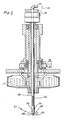
- a conventional spinner disc 11 is shown through the center of which concentric hollow shafts 23 and 24 are placed.
- the shafts are secured to the supporting apparatus of the spinner discs such that the shafts are stable. Specifically, the shafts are clamped as shown in FIG. 2 with clamps 25 as is known in the art.
- Holes 26 are provided in the outer shaft 23 through which air 27 or other gas may be directed.
- the inner hollow shaft 24, concentric with the outer hollow shaft 23, includes a conventional binder nozzle 28 at the end thereof to allow binder 29 to be pumped through the center hollow shaft 24 and out nozzle 27 thereby impacting the fiber column at the central void area thereof. That is, the void area 14 shown in FIG. 1 beneath the spinning disc is now subject to positive air 27 and binder 29 pressure through the hollow shafts 23 and 24.
- FIG. 3 a side sectional view of outer hollow shaft 23 including air nozzles 26 is shown. Specifically, air nozzles 26 are drilled in the shaft at an angle of 30 degrees from the axis of the shaft. It has been found that the angle of 60 degrees downwardly from the horizontal or 30 degrees from the vertical axis of the shaft is optimum for modifying the fiber column.
- the shaft can only extend a portion of the distance from the spinner disc 11 to the apex 22 of the fiber cone because, if extended too far, the fiber tends to collect on the lower portion of the hollow shaft and thus block the air or binder flow.
- the shaft 23 may be made short enough to extend above the apex 22 of the fiber column and yet the downward angle of the nozzles 26 allows the air to be blown closer to the apex 22 thus modifying the fiber column out into an essentially cylindrical column as shown in FIG. 5. It has been found that the number and placement of the air nozzles determines the shape of the resulting fiber distribution pattern. That is, with 3 air nozzles on either side of the hollow shaft 23, the fiber pattern may be a cigar shaped or a "paint brush" pattern 31 as shown in FIG. 6. This long, narrow pattern is advantageous in certain fiber manufacturing operations in which the manufacturing apparatus is oscillated back and forth over the collection chain as previously described.
- FIG. 4 a side view of the central binder shaft 24 and outer shaft 23 is shown.
- a conventional nozzle array 28 through which liquid binder 29 may be pumped and sprayed onto the interior of the fiber column.
- the exterior of the fiber column may additionally be sprayed with binder thus providing for a more complete and uniform coating of the binder onto the fiber.
- the binder is sprayed only onto the outside of the column and thus the fibers in the interior of the column may be incompletely coated with binder.
- FIG. 5 a side sectional view of the fiber production apparatus including the present invention is shown.
- the concentric hollow shafts 23 and 24 through the fiberizer disc are shown.
- Streams of air 27 are directed as described previously at an angle of 60 degrees downwardly from the horizontal to push the fiber column outward and allow the column configuration to be modified.
- the binder 29 is sprayed from the end of the binder shaft onto the interior of the fiber column.
- binder 29 may also be sprayed onto the outside of the fiber column with conventional apparatus (not shown).
- the pattern of the fiber column may be altered in a number of configurations.
- FIG. 6 a top view of the fiberizing apparatus is shown. This more particularly illustrates the shape of the preferred fiber pattern for the present invention.
- the fiber column from fiberizing discs is manipulated into a cigar shaped or paint brush pattern 31. That is, the air nozzles 26 are placed in two vertical rows on the opposite sides of the air wand or shaft 23. Because air is directed in only two directions from the air wand the resulting fiber pattern is pushed outwardly into the pattern shown. However, as can be seen from the orientation of FIG. 6, the air nozzles are not in line with the resulting fiber pattern. This is because of the rotation of the fiber column as it emanates from the fiberizer disc.
- the fiber column will also rotate in a clockwise direction 32.
- the air nozzles in the air wand are oriented at approximately 45 degrees from the longitudinal axis of the desired paint brush pattern to adjust for rotation 32 of the fiber column such that it is properly oriented as it impacts the collection chain. Variables in the fiberizer operation and the distance from the fiberizer to the collection chain require this directional adjustment of the air nozzles.
- the side to side oscillation of the fiberizing unit thus allows this paint brush pattern to be swept across the width of the collection chain as illustrated by arrows 33.
- the length of the air wand 23 and binder spray shaft 24 is important. If the air nozzles and binder nozzles are too close to the fiberizing discs, that is if the shafts are too short, the reconfiguration effect on the fiber column is reduced. The longer the shafts and the closer the air nozzles are to the apex 22 of the conical fiber pattern the more effective these nozzles are in spreading or modifying the fiber column to approach the desired shape. However, as discussed above, if the shafts are made too long, the fiber tends to collect on the lower portion of the shafts and stick thereto. This adversely effects the performance of the air and binder nozzles.
- the binder spray nozzle size is also important to prevent too much or too little binder from being applied to the inside of the fiber column.
- the binder nozzle type and size may be selected using standard engineering design considerations.
- the column pattern may be adjusted to specific desired configurations. That is, as shown in FIG. 6, a "paint brush" pattern 31 has been developed to allow side to side oscillation of the fiberization apparatus to produce a uniform flow of fiber across the chain collection apparatus 18. It has been also advantageously found that, using the present invention, the fibers tend to be oriented in the machine or lengthwise direction (parallel to direction of movement of chain 18). Such orientation improves the tensile strength of the resulting mat produced by the collected fibers. That is, while fibers tended to be randomly oriented with the rotating prior art pattern, they tend to be oriented in a single direction with the present invention. This allows better engineering of the resulting mat. In addition, a wider paint brush pattern allows slower oscillations and/or higher production line speeds.
- Suction apparatus 19 has been used below prior art chain collection devices in order to ensure that the collected fibers remain on the collection chain. It has been found that the employment of the present invention allows a reduction in the amount of suction put on the chain. As can be appreciated, this results in lower energy costs and better production processes. Finally, through proper flow of the air and binder, the fiber column is kept open and is more receptive to the binder application. The more uniform application of binder allows more uniform collection and thus improves the thermal performance characteristics of the resulting mat. A more uniform fiber mat results in better insulation capabilities because low density glass fiber areas allow heat flow resulting in poorer thermal performance. Thus, more uniform distribution is preferred.
- a total of six 1/8 ⁇ holes were drilled at a 60° angle downward from the horizontal. That is, 3 holes on each side of the air wand were employed as discussed above.
- the pattern disclosed in FIG. 6 was achieved.
- the fiber column can be altered to other desired patterns.
- tensile strength, oscillation pattern, and fiber lay on a chain are all improved and a better mat can be produced using the present invention.
- any rotary fiber forming process may advantageously employ the method and apparatus disclosed and claimed herein.
- Refractory fiber, plastic fiber, sol-gel processes, or any other inorganic or organic fiber forming processes may employ the present invention.
- the fibers are shown as extruded from a spinner disc, it should be appreciated that manufacturing processes in which a molten stream inpinges on a rotating solid disc or tire is used may also employ the present invention. That is, the fiber columns which result from such conventional manufacturing processes may also be improved by utilizing the present invention in the center of the fiber column.
Landscapes
- Chemical & Material Sciences (AREA)
- Engineering & Computer Science (AREA)
- Life Sciences & Earth Sciences (AREA)
- Materials Engineering (AREA)
- Geochemistry & Mineralogy (AREA)
- General Life Sciences & Earth Sciences (AREA)
- Organic Chemistry (AREA)
- Manufacturing & Machinery (AREA)
- Chemical Kinetics & Catalysis (AREA)
- General Chemical & Material Sciences (AREA)
- Spinning Methods And Devices For Manufacturing Artificial Fibers (AREA)
- Manufacture, Treatment Of Glass Fibers (AREA)
- Inorganic Fibers (AREA)
- Treatment Of Fiber Materials (AREA)
- Nonwoven Fabrics (AREA)
Abstract
Description
- The invention relates to the field of fiber manufacture. More particularly, the invention relates to the manufacture of fiber by a rotary process. In still greater particularity, the invention relates to a rotary fiberization process in which a gas or a liquid may be directed toward the manufactured fiber. By way of further characterization, but not by way of limitation thereto, the invention includes a means for directing air and binder into the center of the cone produced by the rotary fiberization process in order to reshape the fiber pattern.
- In existing rotary fiber glass processes, the glass fibers are formed from a rotating disc and attenuated in proximity to that rotating disc. An air ring outside the circumference of the rotating disc is used to direct the fibers downwardly and to assist in attenuating those fibers. This air and fiber movement creates a negative pressure zone below the rotating disc. The negative pressure zone, combined with a binder spray system which is sprayed from outside the column with an inward radial spray pattern tends to configure the column of fiber into a conical shape. Concerns with roping and/or hanking of the fiber may thus be aggravated. This leads to degradation of density and binder distribution in the resulting fiber blanket which may cause less than desirable physical and thermal performance characteristics.
- Referring to FIG. 1, a
spinner 11 is shown suspended by an existing support and bearingassembly 16. A stream ofmolten glass 21 is dropped onto the rotatingspinner 11 and the molten glass is extruded fromholes 17 in the circumference of the rotating spinner. Streams of air from anair ring 12 around the circumference of the rotating spinner direct the fiber downwardly and assist in attenuating the fibers.Binder nozzles 15 are located around the circumference of the spinner such that binder may be sprayed onto the fibers as they are directed downwardly onto a conventionalchain collection system 18. Such a rotary fiberization process is disclosed in U.S. Patent No. 4,058,386 incorporated herein by reference. - The rotating spinner assembly along with the air jets may be oscillated back and forth across the width of the collection chain system as is described in U.S. Patent 3,997,307 incorporated by reference herein. The oscillation and the rotating fiber pattern may result in the somewhat uneven distribution of the fibers onto the collection chain. In addition, the fibers tend to be randomly oriented on the fiber chain collection system. A
suction system 19 is used beneath the chain system to improve the distribution of the fibers on the chain system by removing air which is added to the fiber column by the air nozzles. This suction also prevents fibers from being blown into the air surrounding the collection system. - The method and apparatus of the present invention adds air and binder to the fiber from the center of the fiber column. That is, the spinner shaft is modified by adding means for introducing a gas and/or a liquid into the void area below the rotating disc. In particular, in a fiber glass rotary process, concentric hollow shafts are placed in the center of the rotating spinner disc and extend below the disc into the void area produced by the fiber column. Binder and air may be delivered through these hollow shafts or pipes in order to alter the shape of the fiber column and to spray binder onto the inside of the fiber column. Thus, the column of fiber is more receptive to binder application. The fiber column may then be more uniformly collected and this results in improved thermal performance characteristics of the resulting mat.
-
- FIG. 1 is a partially sectioned side view of a prior art rotary fiber apparatus;
- FIG. 2 is a side sectional view of a rotary fiber disc with concentric hollow shafts of the present invention there through;
- FIG. 3 is a side sectional view of the hollow shaft illustrating air distribution nozzles in the hollow shaft;
- FIG. 4 is a side view of the concentric hollow shafts utilized in the present invention;
- FIG. 5 is a side sectional view of a rotary fiberization process illustrating the present invention; and
- FIG. 6 is a top view of the fiber pattern produced by the method and apparatus of the present invention.
- Referring to FIG. 1, a prior art rotary fiberization process is shown. A molten stream of
glass 21 is directed downwardly onto spinningdisc 11 and the glass is then forced throughholes 17 in the periphery of the spinningdisc 11 to producefibers 13. These fibers are directed downwardly by highvelocity air jets 12 and binder is sprayed onto the fiber column bybinder nozzles 15. The fiber column is generally conically shaped with an apex 22 a known distance below the spinner disc. A negative pressure zone or void area 14 is found below the disc by the movement of the fiber, binder, and air. The fibers are directed onto aconventional collection chain 18. - Referring to FIG. 2, a
conventional spinner disc 11 is shown through the center of which concentrichollow shafts clamps 25 as is known in the art.Holes 26 are provided in theouter shaft 23 through whichair 27 or other gas may be directed. The innerhollow shaft 24, concentric with the outerhollow shaft 23, includes aconventional binder nozzle 28 at the end thereof to allowbinder 29 to be pumped through the centerhollow shaft 24 and outnozzle 27 thereby impacting the fiber column at the central void area thereof. That is, the void area 14 shown in FIG. 1 beneath the spinning disc is now subject topositive air 27 and binder 29 pressure through thehollow shafts - Referring to FIG. 3, a side sectional view of outer
hollow shaft 23 includingair nozzles 26 is shown. Specifically,air nozzles 26 are drilled in the shaft at an angle of 30 degrees from the axis of the shaft. It has been found that the angle of 60 degrees downwardly from the horizontal or 30 degrees from the vertical axis of the shaft is optimum for modifying the fiber column. The shaft can only extend a portion of the distance from thespinner disc 11 to theapex 22 of the fiber cone because, if extended too far, the fiber tends to collect on the lower portion of the hollow shaft and thus block the air or binder flow. By providing a downward angle on theair nozzles 26, theshaft 23 may be made short enough to extend above theapex 22 of the fiber column and yet the downward angle of thenozzles 26 allows the air to be blown closer to theapex 22 thus modifying the fiber column out into an essentially cylindrical column as shown in FIG. 5. It has been found that the number and placement of the air nozzles determines the shape of the resulting fiber distribution pattern. That is, with 3 air nozzles on either side of thehollow shaft 23, the fiber pattern may be a cigar shaped or a "paint brush"pattern 31 as shown in FIG. 6. This long, narrow pattern is advantageous in certain fiber manufacturing operations in which the manufacturing apparatus is oscillated back and forth over the collection chain as previously described. - Referring to FIG. 4, a side view of the
central binder shaft 24 andouter shaft 23 is shown. At the end of thebinder shaft 24 is aconventional nozzle array 28 through whichliquid binder 29 may be pumped and sprayed onto the interior of the fiber column. The exterior of the fiber column may additionally be sprayed with binder thus providing for a more complete and uniform coating of the binder onto the fiber. As discussed previously, in prior art apparatus the binder is sprayed only onto the outside of the column and thus the fibers in the interior of the column may be incompletely coated with binder. - Referring to FIG. 5, a side sectional view of the fiber production apparatus including the present invention is shown. The concentric
hollow shafts air 27 are directed as described previously at an angle of 60 degrees downwardly from the horizontal to push the fiber column outward and allow the column configuration to be modified. In addition, thebinder 29 is sprayed from the end of the binder shaft onto the interior of the fiber column. As above,binder 29 may also be sprayed onto the outside of the fiber column with conventional apparatus (not shown). Depending on the number and orientation of the air nozzles, the pattern of the fiber column may be altered in a number of configurations. - Referring to FIG. 6, a top view of the fiberizing apparatus is shown. This more particularly illustrates the shape of the preferred fiber pattern for the present invention. Specifically, the fiber column from fiberizing discs is manipulated into a cigar shaped or paint
brush pattern 31. That is, theair nozzles 26 are placed in two vertical rows on the opposite sides of the air wand orshaft 23. Because air is directed in only two directions from the air wand the resulting fiber pattern is pushed outwardly into the pattern shown. However, as can be seen from the orientation of FIG. 6, the air nozzles are not in line with the resulting fiber pattern. This is because of the rotation of the fiber column as it emanates from the fiberizer disc. That is, assuming the fiberizer disc is rotating in a clockwise rotation as viewed from above, the fiber column will also rotate in aclockwise direction 32. The air nozzles in the air wand are oriented at approximately 45 degrees from the longitudinal axis of the desired paint brush pattern to adjust forrotation 32 of the fiber column such that it is properly oriented as it impacts the collection chain. Variables in the fiberizer operation and the distance from the fiberizer to the collection chain require this directional adjustment of the air nozzles. The side to side oscillation of the fiberizing unit thus allows this paint brush pattern to be swept across the width of the collection chain as illustrated byarrows 33. - In addition to the orientation of the
air nozzles 26, the length of theair wand 23 andbinder spray shaft 24 is important. If the air nozzles and binder nozzles are too close to the fiberizing discs, that is if the shafts are too short, the reconfiguration effect on the fiber column is reduced. The longer the shafts and the closer the air nozzles are to the apex 22 of the conical fiber pattern the more effective these nozzles are in spreading or modifying the fiber column to approach the desired shape. However, as discussed above, if the shafts are made too long, the fiber tends to collect on the lower portion of the shafts and stick thereto. This adversely effects the performance of the air and binder nozzles. It was found that with a 15 inch diameter spinner disc a placement of the air and binder nozzles approximately 10 inches below the fiberizer disc was optimum. For larger diameter spinner discs the air and binder nozzles should be placed a greater distance from the spinner discs. It can be detemined empirically where theapproximate apex 22 of the fiber cone is depending on the diameter of the fiberizer disc. Thus, various placements of the air and binder nozzles may be made to achieve specified purposes and distribution of the fiber column. - It is also important that the air and binder delivery shafts extending through the fiberizer discs be secured. That is, if the shafts are improperly secured to the supporting apparatus above the fiberizer discs, excessive vibration or rotation could occur resulting in damage to the shafts and/or discs and resulting in improper direction of the air and binder spray. The binder spray nozzle size is also important to prevent too much or too little binder from being applied to the inside of the fiber column. The binder nozzle type and size may be selected using standard engineering design considerations.
- Advantages of the air and binder wands are that the column pattern may be adjusted to specific desired configurations. That is, as shown in FIG. 6, a "paint brush"
pattern 31 has been developed to allow side to side oscillation of the fiberization apparatus to produce a uniform flow of fiber across thechain collection apparatus 18. It has been also advantageously found that, using the present invention, the fibers tend to be oriented in the machine or lengthwise direction (parallel to direction of movement of chain 18). Such orientation improves the tensile strength of the resulting mat produced by the collected fibers. That is, while fibers tended to be randomly oriented with the rotating prior art pattern, they tend to be oriented in a single direction with the present invention. This allows better engineering of the resulting mat. In addition, a wider paint brush pattern allows slower oscillations and/or higher production line speeds. -
Suction apparatus 19 has been used below prior art chain collection devices in order to ensure that the collected fibers remain on the collection chain. It has been found that the employment of the present invention allows a reduction in the amount of suction put on the chain. As can be appreciated, this results in lower energy costs and better production processes. Finally, through proper flow of the air and binder, the fiber column is kept open and is more receptive to the binder application. The more uniform application of binder allows more uniform collection and thus improves the thermal performance characteristics of the resulting mat. A more uniform fiber mat results in better insulation capabilities because low density glass fiber areas allow heat flow resulting in poorer thermal performance. Thus, more uniform distribution is preferred. - In the preferred embodiment, a total of six 1/8¨ holes were drilled at a 60° angle downward from the horizontal. That is, 3 holes on each side of the air wand were employed as discussed above. At an air pressure of 60 psi, and with a 45° shaft angle to the desired orientation, the pattern disclosed in FIG. 6 was achieved. By varying the number of holes, the pattern, the induced angle, the hole size, and the air pressure, the fiber column can be altered to other desired patterns. Thus, tensile strength, oscillation pattern, and fiber lay on a chain are all improved and a better mat can be produced using the present invention.
- While the invention has been disclosed with respect to a preferred embodiment thereof, the claims are not to be so limited as changes and modifications may be made which are within the full intended scope of the invention as defined by these appended claims. For example, various hole patterns may be utilized to alter the shape of the resulting fiber lay pattern. If the holes were made sufficient in number, size, and with sufficient air pressure there through, it may be possible to eliminate the required oscillation in the fiber manufacturing apparatus. That is, the paint brush pattern shown in FIG. 6 may be turned 90° across the collection chain width and the oscillation eliminated. The elimination of this oscillation would be a desirable improvement in the fiber manufacturing process. As can be appreciated, such elimination of the oscillation would reduce mechanical problems associated with the oscillation mechanism.
- While the invention has been disclosed as used in a fiber glass manufacturing process, it should be appreciated that any rotary fiber forming process may advantageously employ the method and apparatus disclosed and claimed herein. Refractory fiber, plastic fiber, sol-gel processes, or any other inorganic or organic fiber forming processes may employ the present invention. In addition, while the fibers are shown as extruded from a spinner disc, it should be appreciated that manufacturing processes in which a molten stream inpinges on a rotating solid disc or tire is used may also employ the present invention. That is, the fiber columns which result from such conventional manufacturing processes may also be improved by utilizing the present invention in the center of the fiber column.
Claims (10)
means, in said void area, for introducing a gas, or a liquid into said column of fibers.
impinging a liquid stream onto a rotating disc extruding said liquid stream through holes in the periphery of said rotaing disc to produce fibers;
directing said fibers from the periphery of said rotating disc into a generally circular fiber column defining a void area therein;
providing a positive pressure inside said circular fiber column to thereby alter the configuration to a desired fiber column configuration; and
collecting the fibers from said desired fiber column configuration.
Applications Claiming Priority (2)
| Application Number | Priority Date | Filing Date | Title |
|---|---|---|---|
| US07/156,052 US4832723A (en) | 1988-02-16 | 1988-02-16 | Apparatus for producing desired fiber column configuration |
| US156052 | 1988-02-16 |
Publications (2)
| Publication Number | Publication Date |
|---|---|
| EP0329118A2 true EP0329118A2 (en) | 1989-08-23 |
| EP0329118A3 EP0329118A3 (en) | 1990-10-24 |
Family
ID=22557882
Family Applications (1)
| Application Number | Title | Priority Date | Filing Date |
|---|---|---|---|
| EP19890102614 Withdrawn EP0329118A3 (en) | 1988-02-16 | 1989-02-16 | Method and apparatus for producing desired fiber column configuration |
Country Status (4)
| Country | Link |
|---|---|
| US (1) | US4832723A (en) |
| EP (1) | EP0329118A3 (en) |
| JP (1) | JPH0663126B2 (en) |
| CA (1) | CA1320027C (en) |
Cited By (7)
| Publication number | Priority date | Publication date | Assignee | Title |
|---|---|---|---|---|
| EP0530843A1 (en) * | 1991-09-06 | 1993-03-10 | Manville Corporation | Method of introducing additives to fibrous products |
| WO1995000454A1 (en) * | 1993-06-21 | 1995-01-05 | Owens-Corning Fiberglas Corporation | Method for manufacturing a mineral fiber product |
| WO1995000453A1 (en) * | 1993-06-21 | 1995-01-05 | Owens-Corning Fiberglas Corporation | Method for manufacturing a mineral fiber product |
| US5595584A (en) * | 1994-12-29 | 1997-01-21 | Owens Corning Fiberglas Technology, Inc. | Method of alternate commingling of mineral fibers and organic fibers |
| CN1051533C (en) * | 1994-12-23 | 2000-04-19 | 欧文斯科尔宁格公司 | Method for fiberizing mineral material with organic material |
| CN1051532C (en) * | 1994-12-23 | 2000-04-19 | 欧文斯科尔宁格公司 | Method for fiberizing mineral material with organic material |
| EP1669330A1 (en) * | 2004-12-07 | 2006-06-14 | Evanite Fiber Corporation | Apparatus and Method for making fibers |
Families Citing this family (17)
| Publication number | Priority date | Publication date | Assignee | Title |
|---|---|---|---|---|
| US5076826A (en) * | 1990-10-19 | 1991-12-31 | Evanite Fiber Corporation | Apparatus and method for making glass fibers |
| US5326241A (en) * | 1991-04-25 | 1994-07-05 | Schuller International, Inc. | Apparatus for producing organic fibers |
| US5100450A (en) * | 1991-07-02 | 1992-03-31 | Manville Corporation | Method and apparatus for producing fibers |
| US6077883A (en) * | 1992-05-19 | 2000-06-20 | Johns Manville International, Inc. | Emulsified furan resin based glass fiber binding compositions, process of binding glass fibers, and glass fiber compositions |
| EP0642476B1 (en) * | 1992-05-19 | 1996-08-14 | Schuller International, Inc. | Glass fiber binding compositions, process of binding glass fibers, and glass fiber compositions |
| US5534612A (en) * | 1992-05-19 | 1996-07-09 | Schuller International, Inc. | Glass fiber binding compositions, process of making glass fiber binding compositions, process of binding glass fibers, and glass fiber compositions |
| US5459183A (en) * | 1993-05-19 | 1995-10-17 | Schuller International, Inc. | Low VOC furan resins and method of reducing VOCS in furan resins |
| CN1042525C (en) * | 1994-06-23 | 1999-03-17 | 冶金工业部钢铁研究总院 | Cooling device for fiber production by rapid condensation method |
| US5779760A (en) * | 1996-09-30 | 1998-07-14 | Owens Corning Fiberglas Technology, Inc. | Fiber manufacturing spinner |
| US6227009B1 (en) * | 1998-12-14 | 2001-05-08 | Michael John Cusick | Method of making long, fine diameter glass fibers and products made with such glass fibers |
| US7743629B2 (en) * | 2002-10-21 | 2010-06-29 | Johns Manville | Process of applying atomized binder to fiberous product using a rotary member |
| US7562540B2 (en) * | 2006-06-16 | 2009-07-21 | Green Material Corporation | Fiberizing device for producing fibers from molten waste |
| WO2010105352A1 (en) | 2009-03-16 | 2010-09-23 | Gabae Technologies, Llc | Apparatus, systems and methods for producing particles using rotating capillaries |
| US8821625B2 (en) | 2010-12-09 | 2014-09-02 | Owens Corning Intellectual Capital, Llc | Apparatus and method for re-circulating wash water used in manufacturing glass fiber products |
| US20120144868A1 (en) * | 2010-12-09 | 2012-06-14 | Owens Corning Intellectual Capital, Llc | Apparatus and method for controlling moisture in the manufacture of glass fiber insulation |
| JP7689736B2 (en) * | 2019-01-14 | 2025-06-09 | プレジデント アンド フェローズ オブ ハーバード カレッジ | Focused Rotary Jet Spinning Devices and Methods of Their Use - Patent application |
| CN110029402B (en) * | 2019-04-17 | 2021-02-05 | 中国科学院长春应用化学研究所 | A microfluidic spinning device and method |
Family Cites Families (23)
| Publication number | Priority date | Publication date | Assignee | Title |
|---|---|---|---|---|
| US3219425A (en) * | 1955-02-25 | 1965-11-23 | Owens Corning Fiberglass Corp | Method and apparatus for forming glass fibers |
| NL273584A (en) * | 1955-02-28 | |||
| US3014235A (en) * | 1955-05-25 | 1961-12-26 | Owens Corning Fiberglass Corp | Method and apparatus for forming fibers |
| US3077751A (en) * | 1955-09-14 | 1963-02-19 | Owens Corning Fiberglass Corp | Method and apparatus for forming and processing fibers |
| US3032813A (en) * | 1957-07-09 | 1962-05-08 | Owens Corning Fiberglass Corp | Apparatus for forming and processing continuous filaments |
| US3022538A (en) * | 1957-09-03 | 1962-02-27 | United States Gypsum Co | Means for manufacturing mineral wool |
| US2944284A (en) * | 1957-10-09 | 1960-07-12 | United States Gypsum Co | Binder distribution and atomizing system for fiberizing apparatus |
| US3030659A (en) * | 1958-12-29 | 1962-04-24 | Owens Corning Fiberglass Corp | Apparatus for producing fibers |
| US3233989A (en) * | 1961-03-31 | 1966-02-08 | Owens Corning Fiberglass Corp | Method and apparatus for forming fibers |
| US3343933A (en) * | 1964-05-08 | 1967-09-26 | Celotex Corp | Binder distribution method for producing mineral wool board |
| FR1588880A (en) * | 1968-09-06 | 1970-03-16 | ||
| SE325506B (en) * | 1969-04-08 | 1970-06-29 | Rockwool Ab | |
| US3650718A (en) * | 1969-11-14 | 1972-03-21 | Westinghouse Electric Corp | Fusion method for spaced conductive element window |
| US4058386A (en) * | 1972-12-22 | 1977-11-15 | Johns-Manville Corporation | Method and apparatus for eliminating external hot gas attenuation in the rotary fiberization of glass |
| US4046539A (en) * | 1974-05-28 | 1977-09-06 | Owens-Corning Fiberglas Corporation | Method and apparatus for producing glass fibers |
| US3997307A (en) * | 1975-07-28 | 1976-12-14 | Johns-Manville Corporation | Method and apparatus for making glass fibers utilizing an oscillating spinner |
| US4277436A (en) * | 1978-04-26 | 1981-07-07 | Owens-Corning Fiberglas Corporation | Method for forming filaments |
| US4342582A (en) * | 1981-09-08 | 1982-08-03 | United States Gypsum Company | Apparatus for fiberization of mineral fiber having directional shroud |
| US4670034A (en) * | 1985-12-20 | 1987-06-02 | Owens-Corning Fiberglas Corporation | Internal blower for expanding cylindrical veil of mineral fibers and method of using same |
| FI862656A0 (en) * | 1986-06-23 | 1986-06-23 | Partek Ab | ANORDINATION FOR DEFIBRATION AV SMAELT MINERALMATERIAL. |
| FI77638C (en) * | 1987-02-20 | 1989-04-10 | Partek Ab | MINERALULLCENTRIFUG. |
| FI77834C (en) * | 1987-04-06 | 1989-05-10 | Partek Ab | FIBRERINGSANORDNING FOER FRAMSTAELLNING AV MINERALULL. |
| EP0305339A1 (en) * | 1987-08-27 | 1989-03-01 | Flumroc Ag | Process and apparatus for producing mineral fibres or mineral fibre granules, mineral fibre granules and their use |
-
1988
- 1988-02-16 US US07/156,052 patent/US4832723A/en not_active Expired - Fee Related
-
1989
- 1989-01-27 CA CA000589372A patent/CA1320027C/en not_active Expired - Fee Related
- 1989-02-15 JP JP1033881A patent/JPH0663126B2/en not_active Expired - Lifetime
- 1989-02-16 EP EP19890102614 patent/EP0329118A3/en not_active Withdrawn
Cited By (13)
| Publication number | Priority date | Publication date | Assignee | Title |
|---|---|---|---|---|
| EP0530843A1 (en) * | 1991-09-06 | 1993-03-10 | Manville Corporation | Method of introducing additives to fibrous products |
| US5614132A (en) * | 1993-06-21 | 1997-03-25 | Owens Corning Fiberglas Technology, Inc. | Method for manufacturing a mineral fiber product |
| WO1995000453A1 (en) * | 1993-06-21 | 1995-01-05 | Owens-Corning Fiberglas Corporation | Method for manufacturing a mineral fiber product |
| US5458822A (en) * | 1993-06-21 | 1995-10-17 | Owens-Corning Fiberglas Technology, Inc. | Method for manufacturing a mineral fiber product |
| US5490961A (en) * | 1993-06-21 | 1996-02-13 | Owens-Corning Fiberglas Technology, Inc. | Method for manufacturing a mineral fiber product |
| WO1995000454A1 (en) * | 1993-06-21 | 1995-01-05 | Owens-Corning Fiberglas Corporation | Method for manufacturing a mineral fiber product |
| US5736475A (en) * | 1993-06-21 | 1998-04-07 | Owens Corning Fiberglas Technology, Inc. | Mineral fiber product containing polymeric material |
| CN1051533C (en) * | 1994-12-23 | 2000-04-19 | 欧文斯科尔宁格公司 | Method for fiberizing mineral material with organic material |
| CN1051532C (en) * | 1994-12-23 | 2000-04-19 | 欧文斯科尔宁格公司 | Method for fiberizing mineral material with organic material |
| US5595584A (en) * | 1994-12-29 | 1997-01-21 | Owens Corning Fiberglas Technology, Inc. | Method of alternate commingling of mineral fibers and organic fibers |
| EP1669330A1 (en) * | 2004-12-07 | 2006-06-14 | Evanite Fiber Corporation | Apparatus and Method for making fibers |
| US7481076B2 (en) | 2004-12-07 | 2009-01-27 | Evanite Fiber Corporation | Apparatus for making fibers |
| CN1803682B (en) * | 2004-12-07 | 2011-06-01 | 伊万奈特纤维公司 | Apparatus and method for making fibers |
Also Published As
| Publication number | Publication date |
|---|---|
| JPH0663126B2 (en) | 1994-08-17 |
| US4832723A (en) | 1989-05-23 |
| CA1320027C (en) | 1993-07-13 |
| JPH0274603A (en) | 1990-03-14 |
| EP0329118A3 (en) | 1990-10-24 |
Similar Documents
| Publication | Publication Date | Title |
|---|---|---|
| US4832723A (en) | Apparatus for producing desired fiber column configuration | |
| US5232638A (en) | Apparatus and method for introducing additives to fibrous products | |
| US3650716A (en) | Method of and apparatus for the production of fibers from thermoplastic materials, particularly glass fibers | |
| US4277436A (en) | Method for forming filaments | |
| US5900206A (en) | Method of making a fibrous pack | |
| WO1999026893A1 (en) | A method of forming a pack of organic and mineral fibers | |
| US6113818A (en) | Method and apparatus for integrating organic fibers with mineral fibers | |
| US3877911A (en) | Method and apparatus for producing fibers | |
| JP4842481B2 (en) | Method and apparatus for forming mineral cotton by internal centrifugation | |
| US4359444A (en) | Method for forming filaments | |
| JPH06504256A (en) | Method and apparatus for producing slag fiber | |
| US3343933A (en) | Binder distribution method for producing mineral wool board | |
| US2980952A (en) | Apparatus for forming fibers | |
| CA2037426C (en) | Open bottomed spinner for mineral fibers | |
| US5100450A (en) | Method and apparatus for producing fibers | |
| CA2208125A1 (en) | Method for fiberizing mineral material with organic material | |
| US7743629B2 (en) | Process of applying atomized binder to fiberous product using a rotary member | |
| NZ218689A (en) | Apparatus for expanding veil of mineral fibres: internal blower discharges gases into contact with interior of veil | |
| US3649233A (en) | Method of and apparatus for the production of glass or other fibers from thermoplastic materials | |
| US3077751A (en) | Method and apparatus for forming and processing fibers | |
| US2450914A (en) | Apparatus and process for the manufacture of mineral wool | |
| US5693117A (en) | Radial rotary fiberizer | |
| US4342582A (en) | Apparatus for fiberization of mineral fiber having directional shroud | |
| JPH0158137B2 (en) | ||
| PL203427B1 (en) | Apparatus and process for producing mineral fibres using a rotor and including a binder supply |
Legal Events
| Date | Code | Title | Description |
|---|---|---|---|
| PUAI | Public reference made under article 153(3) epc to a published international application that has entered the european phase |
Free format text: ORIGINAL CODE: 0009012 |
|
| AK | Designated contracting states |
Kind code of ref document: A2 Designated state(s): BE DE ES FR GB IT NL SE |
|
| PUAL | Search report despatched |
Free format text: ORIGINAL CODE: 0009013 |
|
| AK | Designated contracting states |
Kind code of ref document: A3 Designated state(s): BE DE ES FR GB IT NL SE |
|
| 17P | Request for examination filed |
Effective date: 19901009 |
|
| 17Q | First examination report despatched |
Effective date: 19920131 |
|
| STAA | Information on the status of an ep patent application or granted ep patent |
Free format text: STATUS: THE APPLICATION IS DEEMED TO BE WITHDRAWN |
|
| 18D | Application deemed to be withdrawn |
Effective date: 19920611 |