EP0328618B1 - Improved microwave apparatus - Google Patents
Improved microwave apparatus Download PDFInfo
- Publication number
- EP0328618B1 EP0328618B1 EP88907886A EP88907886A EP0328618B1 EP 0328618 B1 EP0328618 B1 EP 0328618B1 EP 88907886 A EP88907886 A EP 88907886A EP 88907886 A EP88907886 A EP 88907886A EP 0328618 B1 EP0328618 B1 EP 0328618B1
- Authority
- EP
- European Patent Office
- Prior art keywords
- cavity
- probe
- plate
- micrometer
- sliding
- Prior art date
- Legal status (The legal status is an assumption and is not a legal conclusion. Google has not performed a legal analysis and makes no representation as to the accuracy of the status listed.)
- Expired - Lifetime
Links
- 239000000523 sample Substances 0.000 claims abstract description 45
- 230000008878 coupling Effects 0.000 claims description 5
- 238000010168 coupling process Methods 0.000 claims description 5
- 238000005859 coupling reaction Methods 0.000 claims description 5
- 238000005259 measurement Methods 0.000 claims 1
- 230000007246 mechanism Effects 0.000 description 7
- 210000002381 plasma Anatomy 0.000 description 7
- 239000010453 quartz Substances 0.000 description 3
- VYPSYNLAJGMNEJ-UHFFFAOYSA-N silicon dioxide Inorganic materials O=[Si]=O VYPSYNLAJGMNEJ-UHFFFAOYSA-N 0.000 description 3
- 238000010438 heat treatment Methods 0.000 description 2
- 230000000694 effects Effects 0.000 description 1
- 230000005684 electric field Effects 0.000 description 1
- 239000000463 material Substances 0.000 description 1
- 238000000034 method Methods 0.000 description 1
Images

Classifications
-
- H—ELECTRICITY
- H01—ELECTRIC ELEMENTS
- H01P—WAVEGUIDES; RESONATORS, LINES, OR OTHER DEVICES OF THE WAVEGUIDE TYPE
- H01P7/00—Resonators of the waveguide type
- H01P7/06—Cavity resonators
Definitions
- the present invention relates to a radio frequency wave generating apparatus including a metallic radio frequency wave cavity which is excited in one or more of its modes of resonance, in the cavity around a central axis of the cavity, including movable plate means in the cavity mounted perpendicular to the central axis in the cavity and movable along the central axis, movable probe means connected to and extending inside the cavity for coupling the radio frequency wave to the cavity, and control means for controlling the probe means and plate means in order to select and control the mode of the radio frequency wave in the cavity, which comprises:
- US-A-2,543,809 discloses an ultra-high frequency electrical apparatus for coupling loops for transferring electromagnetic energy to and from activity resonators.
- This apparatus discloses a movable plate which is movable along the central axis of a cavity, whereby the position of the plate is measured by a micrometer-type barrel.
- US-A-2,311,520 describes an electron discharge device comprising an evacuated hollow body resonator which is preferably provided with two coupling means.
- the coupling means comprises a cup-shaped head with a micrometer-like scale provided at its outside.
- a radio frequency wave generating apparatus which further comprises:
- the apparatus preferably includes magnets surrounding the chamber and mounted on the sliding short in order to confine the plasma in the chamber to the extent desired. This apparatus is described in U.S. Appl. Ser. No. 849,052, filed April 7, 1986.
- the apparatus can be used to practice the method of U.S. Application Serial No. 41,291, filed April 22, 1987.
- the patterns of heating of materials are determined as a function of time. Further, the changing dielectric constants as a function of the heating can be determined.
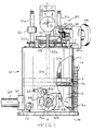
- Figure 1 is a front partial sectional view of the preferred apparatus 10 of the present invention particularly showing a mechanism 20 for moving the plate 13 in the cavity 12 and a micrometer 37 for measuring changes of the position of the plate 13.
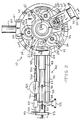
- Figure 2 is a plan view of the apparatus 10 of Figure 1 showing the mechanism 40 for moving the probe 15 in the cavity 12.
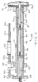
- Figure 3 is a front cross-sectional view of the apparatus of Figure 1 showing the mechanism 20.
- Figure 4 is a plan cross-sectional view of the mechanism 40 for moving the probe 15, particularly showing a micromoter 52 for measuring the changes of position of the probe 15 in the cavity 12.
- Figures 1 to 3 show the preferred radiofrequency wave generating apparatus 10 of the present invention.
- Figure 4 shows a portion of the apparatus 10.
- a circularly cross-sectioned, electrically conductive housing 11 defines a cavity 12 around longitudinal axis a-a for the radiofrequency wave along with a moveable plate 13 and a fixed plate 14 which are also electrically conductive.
- Conductive fingers (preferably metallic) 13a and 14a engage an inside wall 11a of the housing 11.
- a probe 15 ( Figure 4) is moveable into and out of the cavity 12 and couples the radiofrequency wave to the cavity 12.
- a conductive grid or screen 16 is mounted on fixed plate 14 and mounts the fingers 14a. The plate 14 can mount the fingers 14a (not shown).
- the fixed plate 14 has an opening 14a adjacent the cavity 12 and around the axis a-a to allow plasma formed in the cavity 12 to be removed.
- the cavity 12 could be closed.
- a non-conductive cup shaped member 17 (preferably quartz) sealingly covers the opening 14a of plate 14.
- a quartz tube for confining the plasma (not shown) can be inserted through the apparatus along axis a-a in place of cup shaped member 17.
- the apparatus can also be used for radiofrequency wave processing in chamber 12.
- the fixed plate 14 is secured to a vacuum source (not shown) by means of bolts 11f.
- the cup shaped member 17 and plate 14 define a plasma chamber 18 which is filled with a gas to create the plasma by a gas supply lines 19 and 19a.
- the basic system is described in U.S Patent Nos. 4,507,588; 4,585,668 and 4,630,566.
- the improvement in the present invention relates to the mechanisms 20 and 40 for moving the probe 15 and moveable plate 13 in the cavity 12.
- the mechanism 20 includes three externally threaded posts 21a, 21b and 21c attached to the plate 13 and mounted through a top portion 11b of the housing 11.
- planetary gears 22a, 22b and 22c are rotatably mounted on the top portion 11b of the housing 11 on internal cover 11c by means of support members 23a, 23b and 23c and screws 24.
- the support member 23a includes a bearing 23d and spindle 23d supporting gear 22a.
- Support members 23b and 23c are constructed in the same manner.
- Central gear 25 is rotatably mounted around the axis a-a on bracket 26 on top portion 11b by means of screws 27.
- Bracket 26 includes a bearing 26a and spindle 26b which mounts central gear 25 so as to engage each of the planetary gears 22a, 22b and 22c.
- a side gear 28 engages the central gear and is mounted on a shaft 29.
- the shaft 29 is mounted in a C-shaped member 30.
- First bevel gear 31 is mounted on shaft 29 and is engaged by second bevel gear 32 mounted on shaft 33 and rotatably supported at right angles to shaft 29 on C-shaped member 30.
- a rotatable knob 34 is secured to shaft 33 and includes indicia 35 ( Figure 2) for determining increments of position of the knob 34 relative to the C-shaped member 30.
- Stop 36 is in threaded engagement with shaft 21a to prevent movement of the plate 13 beyond a particular point in the cavity 12.
- the plate 13 is moved along axis a-a by turning knob 34 which rotates shaft 33, first and second bevel gears 31 and 32, shaft 29 side gear 28, central gear 25 and then planetary gears 22a, 22b and 22c which move posts 21a, 21b and 21c vertically and plate 13.
- the knob 34 can be controlled manually or it can be controlled by a motor (not shown).
- the central gear 25 spindle 26b has an opening 26c along the axis a-a which can be used for inserting a quartz tube (not shown) for a confining plasma or an object to be treated with the radiofrequency waves in cavity 12.
- top portions 11b and internal cover 11c have a central opening 11d and the plate 13 optionally has an internal opening 13c to provide access to cavity 12.
- a micrometer 37 with a fixed stem 32a is secured to top portion 11b and a moveable stem 37b engages the plate 14. Openings 11e are provided for sensors (not shown) to determine the electrical field strength within the cavity 12 at various positions and spacings from the axis a-a. As the plate 13 moves, the micrometer 37 measures the change in position.
- the mechanism 40 controls the probe 15.
- the probe 15 is mounted perpendicular to the axis a-a on axis b-b and is moveable into and out of the cavity 10.
- the probe 15 includes three (3) segments 15a, 15b and 15c which are secured together by threaded extensions 15d and 15e.
- Locating members 41 are mounted around the extensions 15d and 15e and mount the probe 15 inside a tube 42, thereby rigidly mounting the probe 15.
- the tube 42 has fingers 42a for electrical connection to a tubular receiver 43 for the tube 42 mounted on the housing 11 by means of block 44 so that the tube 43 slides into and out of the receiver 43.
- the tube 42 includes an electrical connector 45 with a projection 46 perpendicular to the axis b-b.
- Posts 47 and 48 are mounted parallel to the axis b-b.
- a holder 49 is mounted on the posts 47 and 48 and slideably supports the tube 42.
- a sleeve 50 mounts a rack 51 on the tube 42.
- the holder 49 supports a micrometer 52 with a fixed stem 52a and a moveable stem 52b which engages the projection 46. The position of the moveable stem 52b can be adjusted by means of adjuster 52c on support 52d of the micrometer 52.
- Gear 53 is mounted on shaft 54 ( Figure 4) to engage the rack 50.
- the shaft 54 mounts a knob 55 which is used to rotate the gear 53 and thus move the probe 15 into and out of the cavity 12. In operation the knob 55 can be controlled manually or by a motor (not shown).
- Receiver 60 provides an additional post for another probe (not shown) or for changing the position of the probe 15.
- the receiver 60 is mounted on block 61.
- the control of the probe 15 and plate 13 is by means of knobs 34 and 55.
- the result is a very simple and precise means for making micrometer adjustments of the probe 15 and plate 13 in the cavity 12. This allows the selection of the mode of the radiofrequency wave as well as adjustments to provide fine tuning within a mode.
- Micrometers with a digital readout can be used.
- Motors can be used to move the plate 13 and probe 15. The result is a very useful and commercially acceptable microwave cavity.
Landscapes
- Control Of Motors That Do Not Use Commutators (AREA)
- Plasma Technology (AREA)
- Particle Accelerators (AREA)
Abstract
Description
- The present invention relates to a radio frequency wave generating apparatus including a metallic radio frequency wave cavity which is excited in one or more of its modes of resonance, in the cavity around a central axis of the cavity, including movable plate means in the cavity mounted perpendicular to the central axis in the cavity and movable along the central axis, movable probe means connected to and extending inside the cavity for coupling the radio frequency wave to the cavity, and control means for controlling the probe means and plate means in order to select and control the mode of the radio frequency wave in the cavity, which comprises:
- (a) guiding means movably mounting the plate means in the cavity of the apparatus and providing for precise positioning of the plate means along the central axis;
- (b) support means mounted on the apparatus adjacent an opening in the cavity;
- (c) sliding means mounting the probe means and mounted on a support means so as to linearly move into and out of the opening in the cavity along a longitudinal axis of the probe means, whereby the motive means moves the sliding means; and
- (d) motive means for moving the probe means and guiding means.
- Such an apparatus is known from US-A-4,507,588 which describes the creation of disc plasmas in a chamber wherein the mode and the tuning of the radio frequency wave in a cavity around the chamber is controlled by a movable probe and plate.
- US-A-2,543,809 discloses an ultra-high frequency electrical apparatus for coupling loops for transferring electromagnetic energy to and from activity resonators. This apparatus discloses a movable plate which is movable along the central axis of a cavity, whereby the position of the plate is measured by a micrometer-type barrel.
- US-A-2,311,520 describes an electron discharge device comprising an evacuated hollow body resonator which is preferably provided with two coupling means. The coupling means comprises a cup-shaped head with a micrometer-like scale provided at its outside.
- It is an object of the present invention to provide an improved wave generating apparatus which allows fine, repeatable tuning of the probe and the plate in the cavity so as to control the mode or tuning of the mode in a cavity. Furthermore, the present invention should provide an apparatus which is relatively simple and economical to construct and use.
- The object is solved by a radio frequency wave generating apparatus which further comprises:
- (a) first micrometer means mounted between the support means and the sliding means so as to measure the position of the probe means in the cavity; and
- (b) second micrometer means mounted between a portion of the apparatus and the plate means so as to measure the position of the plate means in the cavity; and whereby
- (c) the sliding means are provided with gearing means as a motive means for movement of the sliding means and probe means together into and out of the cavity;
- (d) the guiding means comprises multiple threaded rods mounted on the plate means parallel to and equally spaced from the central axis and projecting from the apparatus, outer gears with threaded openings mounted on each of the rods outside of the apparatus and a central gear on the central axis which rotates each of the outer gears to move the plate means along the central axis in the cavity and wherein the motive means engages the central gear to move the plate means; and
- (e) the motive means provides precise positioning of the probe means and plate means in the cavity as determined by the first and second micrometer means.
- The apparatus preferably includes magnets surrounding the chamber and mounted on the sliding short in order to confine the plasma in the chamber to the extent desired. This apparatus is described in U.S. Appl. Ser. No. 849,052, filed April 7, 1986.
- The apparatus can be used to practice the method of U.S. Application Serial No. 41,291, filed April 22, 1987. The patterns of heating of materials are determined as a function of time. Further, the changing dielectric constants as a function of the heating can be determined.
- Figure 1 is a front partial sectional view of the
preferred apparatus 10 of the present invention particularly showing amechanism 20 for moving theplate 13 in thecavity 12 and amicrometer 37 for measuring changes of the position of theplate 13. - Figure 2 is a plan view of the
apparatus 10 of Figure 1 showing themechanism 40 for moving theprobe 15 in thecavity 12. - Figure 3 is a front cross-sectional view of the apparatus of Figure 1 showing the
mechanism 20. - Figure 4 is a plan cross-sectional view of the
mechanism 40 for moving theprobe 15, particularly showing amicromoter 52 for measuring the changes of position of theprobe 15 in thecavity 12. - Figures 1 to 3 show the preferred radiofrequency
wave generating apparatus 10 of the present invention. Figure 4 shows a portion of theapparatus 10. A circularly cross-sectioned, electrically conductive housing 11 defines acavity 12 around longitudinal axis a-a for the radiofrequency wave along with amoveable plate 13 and afixed plate 14 which are also electrically conductive. Conductive fingers (preferably metallic) 13a and 14a engage an inside wall 11a of the housing 11. A probe 15 (Figure 4) is moveable into and out of thecavity 12 and couples the radiofrequency wave to thecavity 12. A conductive grid orscreen 16 is mounted onfixed plate 14 and mounts thefingers 14a. Theplate 14 can mount thefingers 14a (not shown). Thefixed plate 14 has an opening 14a adjacent thecavity 12 and around the axis a-a to allow plasma formed in thecavity 12 to be removed. Thecavity 12 could be closed. Preferably a non-conductive cup shaped member 17 (preferably quartz) sealingly covers the opening 14a ofplate 14. A quartz tube for confining the plasma (not shown) can be inserted through the apparatus along axis a-a in place of cup shaped member 17. The apparatus can also be used for radiofrequency wave processing inchamber 12. Thefixed plate 14 is secured to a vacuum source (not shown) by means ofbolts 11f. The cup shaped member 17 andplate 14 define aplasma chamber 18 which is filled with a gas to create the plasma by agas supply lines - The improvement in the present invention relates to the
mechanisms probe 15 andmoveable plate 13 in thecavity 12. Themechanism 20 includes three externally threadedposts plate 13 and mounted through atop portion 11b of the housing 11. As shown in Figure 3,planetary gears top portion 11b of the housing 11 on internal cover 11c by means of support members 23a, 23b and 23c andscrews 24. The support member 23a includes a bearing 23d and spindle23d supporting gear 22a. Support members 23b and 23c are constructed in the same manner.Central gear 25 is rotatably mounted around the axis a-a onbracket 26 ontop portion 11b by means ofscrews 27. Bracket 26 includes a bearing 26a and spindle 26b which mountscentral gear 25 so as to engage each of theplanetary gears side gear 28 engages the central gear and is mounted on ashaft 29. Theshaft 29 is mounted in a C-shaped member 30.First bevel gear 31 is mounted onshaft 29 and is engaged bysecond bevel gear 32 mounted onshaft 33 and rotatably supported at right angles toshaft 29 on C-shaped member 30. Arotatable knob 34 is secured toshaft 33 and includes indicia 35 (Figure 2) for determining increments of position of theknob 34 relative to the C-shapedmember 30.Stop 36 is in threaded engagement withshaft 21a to prevent movement of theplate 13 beyond a particular point in thecavity 12. As can be seen from Figures 1 to 3, theplate 13 is moved along axis a-a by turningknob 34 which rotatesshaft 33, first andsecond bevel gears shaft 29side gear 28,central gear 25 and thenplanetary gears posts plate 13. Theknob 34 can be controlled manually or it can be controlled by a motor (not shown). Thecentral gear 25 spindle 26b has an opening 26c along the axis a-a which can be used for inserting a quartz tube (not shown) for a confining plasma or an object to be treated with the radiofrequency waves incavity 12. Thetop portions 11b and internal cover 11c have a central opening 11d and theplate 13 optionally has aninternal opening 13c to provide access tocavity 12. Amicrometer 37 with a fixed stem 32a is secured totop portion 11b and a moveable stem 37b engages theplate 14. Openings 11e are provided for sensors (not shown) to determine the electrical field strength within thecavity 12 at various positions and spacings from the axis a-a. As theplate 13 moves, themicrometer 37 measures the change in position. - The
mechanism 40 controls theprobe 15. Theprobe 15 is mounted perpendicular to the axis a-a on axis b-b and is moveable into and out of thecavity 10. Theprobe 15 includes three (3) segments 15a, 15b and 15c which are secured together by threadedextensions members 41 are mounted around theextensions probe 15 inside atube 42, thereby rigidly mounting theprobe 15. Thetube 42 hasfingers 42a for electrical connection to atubular receiver 43 for thetube 42 mounted on the housing 11 by means ofblock 44 so that thetube 43 slides into and out of thereceiver 43. Thetube 42 includes anelectrical connector 45 with aprojection 46 perpendicular to the axis b-b.Posts holder 49 is mounted on theposts tube 42. Asleeve 50 mounts arack 51 on thetube 42. Theholder 49 supports amicrometer 52 with afixed stem 52a and amoveable stem 52b which engages theprojection 46. The position of themoveable stem 52b can be adjusted by means ofadjuster 52c onsupport 52d of themicrometer 52.Gear 53 is mounted on shaft 54 (Figure 4) to engage therack 50. Theshaft 54 mounts aknob 55 which is used to rotate thegear 53 and thus move theprobe 15 into and out of thecavity 12. In operation theknob 55 can be controlled manually or by a motor (not shown).Receiver 60 provides an additional post for another probe (not shown) or for changing the position of theprobe 15. Thereceiver 60 is mounted onblock 61. - As can be seen from Figures 1 to 4, the control of the
probe 15 andplate 13 is by means ofknobs probe 15 andplate 13 in thecavity 12. This allows the selection of the mode of the radiofrequency wave as well as adjustments to provide fine tuning within a mode. Micrometers with a digital readout (not shown) can be used. Motors (not shown) can be used to move theplate 13 andprobe 15. The result is a very useful and commercially acceptable microwave cavity. - It is intended that the foregoing description be only illustrative of the present invention and that this invention be limited only by the hereinafter appended claims.
Claims (13)
- A radio frequency wave generating apparatus (10) including a metallic radio frequency wave cavity (12) which is excited in one or more of its modes of resonance in the cavity (12) around a central axis (a-a) of the cavity (12) including movable plate means (13) in the cavity (12) mounted perpendicular to the central axis (a-a) in the cavity (12) and movable along the central axis (a-a), movable probe means (15) connected to and extending inside the cavity (12) for coupling the radio frequency wave to the cavity (12) and control means for controlling the probe means (15) and plate means (13) in order to select and control the mode of the radio frequency wave in the cavity (12), the control means comprising:(a) guiding means (21,22,25) movably mounting the plate means (13) in the cavity (12) of the apparatus (10) and providing for precise positioning of the plate means (13) along the central axis (a-a);(b) support means (47,48) mounted on the apparatus (10) adjacent an opening in the cavity (12);(c) sliding means (41,42,43) mounting the probe means (15) and mounted on said support means for bringing about a linear movement;(d) first and second motive means for moving the probe means (15) and guiding means,characterized in that
the control means further comprises:(e) first micrometer means (52) mounted between the support means and the sliding means so as to measure the position of the probe means (15) in the cavity (12); and(f) second micrometer means (37) mounted between a portion of the apparatus and the plate means (13) so as to measure the position of the plate means (13) in the cavity (12); and whereby(g) the sliding means (41,42,43) are provided with first gearing means (51,53) as a first motive means for movement of the sliding means and probe means (15) together into and out of the cavity (12);(h) the guiding means comprises multiple threaded rods (21a,21b,21c) mounted on the plate means (13) parallel to and equally spaced from the central axis (a-a) and projecting from the apparatus (10), second gear means (20) including outer gears (22a,22b,22c) with threaded openings mounted on each of the rods (21a,21b,21c) outside of the apparatus (10) and a central gear (25) on the central axis (a-a) which rotates each of the outer gears (22a,22b,22c) to move the plate means (13) along the central axis (a-a) in the cavity (12) and wherein the second motive means engages the central gear (25) to move the plate means (13); and(i) the first and second motive means provides precise positioning of the probe means (15) and plate means (13) in the cavity (12) as determined by the first and second micrometer means (37,52). - The apparatus of claim 1 wherein the support means is two spaced apart posts (48,47) mounted on the apparatus (10) with the sliding means mounted between the posts (48,47) and a holder (49) mounted on the posts (48,47) with an opening for the sliding means and wherein the first micrometer means (52) is mounted on the holder (49) between the sliding means and the holder (49).
- The apparatus of claim 1 wherein the first micrometer means (52) includes a movable stem (52b) on the micrometer means (52) which engages a portion of the sliding means so that the change of position of the sliding means and probe means (15) in the opening in the support means is measured by a change of position of the stem (52b).
- The apparatus of claim 1 wherein the second micrometer means (37) is mounted on a portion of the apparatus (10) so that a movable stem (37b) of the micrometer means (37) engages the plate means (13) to thereby measure the change of position of the plate means (13) by a change of position of the movable stem (37b).
- The apparatus of claim 1 wherein the sliding means and guiding means are each controlled by a rotatable knob (55,34) as part of the motive means so that one knob (34) manually moves the plate means (13) and the other knob (55) manually moves the sliding means and probe means (15) together in the cavity.
- The apparatus of claim 5 wherein the knobs (34,55) rotate on a horizontal axis.
- The apparatus of claim 1 wherein the first and second micrometer means (52,37) have dial gauges which measure fine increments of change of position.
- The apparatus of claim 7 wherein in addition the second micrometer means (37) is provided with a linear scale measuring means for gross measurements of the position of the plate means (13) in the cavity (12).
- The apparatus of one of claims 2 to 8 wherein the sliding means are provided with:(a) spaced apart locating members (41) mounted along and around the longitudinal axis (B-B) of the probe means (15),(b) a tube (42) mounted on the locating members (41) along the longitudinal axis (b-b)so that the probe means (15) extends from one end of the tube (42), and(c) a tubular receiver (43) defining an opening into the cavity (12) wherein the tube (42) is slidably mounted in the opening with probe means (15) extending at the one end of the tube (42) into the cavity (12), and wherein the first motive means are provided with:(d) rack means (51) mounted on the tube (42) parallel to the longitudinal axis (b-b) of the probe means (15), and whereby(e) electrical connector means (45) mounted on the tube (42) at an end opposite the one end including a projection (46) away from the longitudinal axis (b-b) of the probe means (15),(f) the holder (49) mounted on the posts (48,47) with an opening slidably supporting the tube (42) between the posts (48,47) and positioning the tube (42) in the opening of the tubular receiver (43),(g) the movable stem (52b) of the first micrometer means (52) engages the projection (46) on the connector means (45),(h) the rotatable first gear means (53) is supported on the holder (49) and engages the rack means (51) to move the tube (42) and probe means (15) into and out of the cavity (12), and(i) the second micrometer means (37) measures the position of the plate means (13) along the central axis (A-A) in the cavity (12).
- The apparatus of claim 9 wherein said other knob (55) is mounted on the holder (49) and connected to the first gear means (53) and wherein said one knob (34) is mounted on the outside of the apparatus (10) and connected to the second gear means (20).
- The apparatus of claim 10 wherein said one knob (34) is connected by shafts (33) and angle gears (31,32) to the second gear means (20).
- The apparatus of claim 10 wherein said other knob (55) rotates on a rotatable shaft (54) mounted on the holder (49) which supports the first gear means (53) engaging the rack means (51).
- The apparatus of claim 9 wherein the opening in the holder (49) is spaced from the opening in the receiver means (43) along the longitudinal axis (B-B) of the probe (15).
Priority Applications (1)
| Application Number | Priority Date | Filing Date | Title |
|---|---|---|---|
| AT88907886T ATE98054T1 (en) | 1987-08-24 | 1988-08-08 | MICROWAVE. |
Applications Claiming Priority (2)
| Application Number | Priority Date | Filing Date | Title |
|---|---|---|---|
| US88377 | 1979-10-26 | ||
| US07/088,377 US4792772A (en) | 1987-08-24 | 1987-08-24 | Microwave apparatus |
Publications (3)
| Publication Number | Publication Date |
|---|---|
| EP0328618A1 EP0328618A1 (en) | 1989-08-23 |
| EP0328618A4 EP0328618A4 (en) | 1989-12-28 |
| EP0328618B1 true EP0328618B1 (en) | 1993-12-01 |
Family
ID=22211022
Family Applications (1)
| Application Number | Title | Priority Date | Filing Date |
|---|---|---|---|
| EP88907886A Expired - Lifetime EP0328618B1 (en) | 1987-08-24 | 1988-08-08 | Improved microwave apparatus |
Country Status (6)
| Country | Link |
|---|---|
| US (1) | US4792772A (en) |
| EP (1) | EP0328618B1 (en) |
| JP (1) | JPH06105843B2 (en) |
| CA (1) | CA1287666C (en) |
| DE (1) | DE3886031T2 (en) |
| WO (1) | WO1989002164A1 (en) |
Families Citing this family (15)
| Publication number | Priority date | Publication date | Assignee | Title |
|---|---|---|---|---|
| US4906900A (en) * | 1989-04-03 | 1990-03-06 | Board Of Trustees Operating Michigan State University | Coaxial cavity type, radiofrequency wave, plasma generating apparatus |
| US6020579A (en) * | 1997-01-06 | 2000-02-01 | International Business Machines Corporation | Microwave applicator having a mechanical means for tuning |
| US6020580A (en) * | 1997-01-06 | 2000-02-01 | International Business Machines Corporation | Microwave applicator having a mechanical means for tuning |
| US5191182A (en) * | 1990-07-11 | 1993-03-02 | International Business Machines Corporation | Tuneable apparatus for microwave processing |
| US5241040A (en) * | 1990-07-11 | 1993-08-31 | International Business Machines Corporation | Microwave processing |
| US6121595A (en) * | 1997-01-06 | 2000-09-19 | International Business Machines Corporation | Applicator to provide uniform electric and magnetic fields over a large area and for continuous processing |
| US5243310A (en) * | 1992-01-27 | 1993-09-07 | The United States Of America As Represented By The Administrator Of The National Aeronautics And Space Administration | Three point lead screw positioning apparatus for a cavity tuning plate |
| US5311103A (en) * | 1992-06-01 | 1994-05-10 | Board Of Trustees Operating Michigan State University | Apparatus for the coating of material on a substrate using a microwave or UHF plasma |
| US5470423A (en) * | 1994-01-25 | 1995-11-28 | Board Of Trustees Operating Michigan State University | Microwave pultrusion apparatus and method of use |
| US5406056A (en) * | 1994-05-02 | 1995-04-11 | Board Of Trustees Operating Michigan State University | Electromagnetic curing apparatus and method of use |
| US5736818A (en) * | 1996-03-15 | 1998-04-07 | Board Of Trustees Operating Michigan State University | Resonant radiofrequency wave plasma generating apparatus with improved stage |
| US6276295B1 (en) | 1997-07-30 | 2001-08-21 | Applied Materials, Inc. | Thermal reflow method employing microwave energy |
| US20030152700A1 (en) * | 2002-02-11 | 2003-08-14 | Board Of Trustees Operating Michigan State University | Process for synthesizing uniform nanocrystalline films |
| US7147810B2 (en) * | 2003-10-31 | 2006-12-12 | Fraunhofer Usa, Inc. | Drapable diamond thin films and method for the preparation thereof |
| US7034266B1 (en) | 2005-04-27 | 2006-04-25 | Kimberly-Clark Worldwide, Inc. | Tunable microwave apparatus |
Family Cites Families (11)
| Publication number | Priority date | Publication date | Assignee | Title |
|---|---|---|---|---|
| US2311520A (en) * | 1941-08-13 | 1943-02-16 | Westinghouse Electric & Mfg Co | Coupling loop |
| US2439388A (en) * | 1941-12-12 | 1948-04-13 | Sperry Corp | Resonator wave meter |
| US2605459A (en) * | 1943-10-23 | 1952-07-29 | Jackson H Cook | Monitoring apparatus for radio pulse transmission systems |
| US2543809A (en) * | 1946-01-08 | 1951-03-06 | Sperry Corp | Coupling loop |
| US2853678A (en) * | 1953-11-16 | 1958-09-23 | Sperry Rand Corp | Millimeter frequency meter |
| US3008102A (en) | 1957-01-16 | 1961-11-07 | Varian Associates | Cavity resonator methods and apparatus |
| DE2056398B2 (en) * | 1970-11-17 | 1973-02-01 | TUNED MAGNETRON | |
| US4507588A (en) * | 1983-02-28 | 1985-03-26 | Board Of Trustees Operating Michigan State University | Ion generating apparatus and method for the use thereof |
| US4585668A (en) * | 1983-02-28 | 1986-04-29 | Michigan State University | Method for treating a surface with a microwave or UHF plasma and improved apparatus |
| US4630566A (en) * | 1984-08-16 | 1986-12-23 | Board Of Trustees Operating Michigan State University | Microwave or UHF plasma improved apparatus |
| US4777336A (en) * | 1987-04-22 | 1988-10-11 | Michigan State University | Method for treating a material using radiofrequency waves |
-
1987
- 1987-08-24 US US07/088,377 patent/US4792772A/en not_active Expired - Lifetime
-
1988
- 1988-08-08 EP EP88907886A patent/EP0328618B1/en not_active Expired - Lifetime
- 1988-08-08 DE DE88907886T patent/DE3886031T2/en not_active Expired - Fee Related
- 1988-08-08 WO PCT/US1988/002673 patent/WO1989002164A1/en not_active Ceased
- 1988-08-08 JP JP63507141A patent/JPH06105843B2/en not_active Expired - Fee Related
- 1988-08-11 CA CA000574475A patent/CA1287666C/en not_active Expired - Lifetime
Also Published As
| Publication number | Publication date |
|---|---|
| US4792772A (en) | 1988-12-20 |
| EP0328618A1 (en) | 1989-08-23 |
| WO1989002164A1 (en) | 1989-03-09 |
| DE3886031D1 (en) | 1994-01-13 |
| CA1287666C (en) | 1991-08-13 |
| JPH01502794A (en) | 1989-09-21 |
| JPH06105843B2 (en) | 1994-12-21 |
| DE3886031T2 (en) | 1994-03-31 |
| EP0328618A4 (en) | 1989-12-28 |
Similar Documents
| Publication | Publication Date | Title |
|---|---|---|
| US4792772A (en) | Microwave apparatus | |
| US6208142B1 (en) | Magnetic resonance apparatus and methods with shim adjustment | |
| US4877999A (en) | Method and apparatus for producing an hf-induced noble-gas plasma | |
| EP2910278A1 (en) | Scanning system | |
| US4698595A (en) | NMR-apparatus with an adjustable RF tuning circuit | |
| WO2015048468A1 (en) | Particle beam scanning | |
| US5781011A (en) | Dielectric resonator-based electron paramagnetic resonance probe | |
| US12281995B2 (en) | System and method for characterizing bioreactor fluids | |
| JP2562289B2 (en) | Double post hollow cavity for NMR probe | |
| US3122703A (en) | Gyromagnetic resonance method and apparatus | |
| EP2249699B1 (en) | Differential tuning of quadrature modes of a magnetic resonance coil | |
| JP3983984B2 (en) | Magnet apparatus, nuclear magnetic resonance imaging apparatus using the same, and magnetic field uniformity adjustment method thereof | |
| US5406056A (en) | Electromagnetic curing apparatus and method of use | |
| Collingwood et al. | Helical resonators for spin resonance spectroscopy | |
| Halliday et al. | A nuclear magnetic resonance spectrometer using a superconducting magnet | |
| US2919419A (en) | Tunable cavity resonator | |
| Slade et al. | An esr spectrometer operating at 4 mm wavelength for the investigation of large zero field splittings | |
| US2992361A (en) | Rapidly tunable magnetron | |
| US3028594A (en) | Self-synchronous tuning system for variable frequency radar system | |
| US3098989A (en) | Serially connected course and fine inductors with continuous adjustment | |
| JP7716676B2 (en) | Nuclear magnetic resonance probe, nuclear magnetic resonance measurement device, and nuclear magnetic resonance measurement method | |
| CN217655156U (en) | Experimental tool for resonance device | |
| Noelle et al. | BPMs with precise alignment for TTF2 | |
| US3242427A (en) | Tunable microwave cavity | |
| Wolfsperger et al. | Automatic field distribution measurement inside of enclosures |
Legal Events
| Date | Code | Title | Description |
|---|---|---|---|
| PUAI | Public reference made under article 153(3) epc to a published international application that has entered the european phase |
Free format text: ORIGINAL CODE: 0009012 |
|
| AK | Designated contracting states |
Kind code of ref document: A1 Designated state(s): AT BE CH DE FR GB IT LI LU NL SE |
|
| 17P | Request for examination filed |
Effective date: 19890908 |
|
| A4 | Supplementary search report drawn up and despatched |
Effective date: 19891228 |
|
| 17Q | First examination report despatched |
Effective date: 19920609 |
|
| GRAA | (expected) grant |
Free format text: ORIGINAL CODE: 0009210 |
|
| AK | Designated contracting states |
Kind code of ref document: B1 Designated state(s): AT BE CH DE FR GB IT LI LU NL SE |
|
| REF | Corresponds to: |
Ref document number: 98054 Country of ref document: AT Date of ref document: 19931215 Kind code of ref document: T |
|
| ITF | It: translation for a ep patent filed | ||
| REF | Corresponds to: |
Ref document number: 3886031 Country of ref document: DE Date of ref document: 19940113 |
|
| ET | Fr: translation filed | ||
| EPTA | Lu: last paid annual fee | ||
| PLBE | No opposition filed within time limit |
Free format text: ORIGINAL CODE: 0009261 |
|
| STAA | Information on the status of an ep patent application or granted ep patent |
Free format text: STATUS: NO OPPOSITION FILED WITHIN TIME LIMIT |
|
| 26N | No opposition filed | ||
| EAL | Se: european patent in force in sweden |
Ref document number: 88907886.1 |
|
| PGFP | Annual fee paid to national office [announced via postgrant information from national office to epo] |
Ref country code: LU Payment date: 19950701 Year of fee payment: 8 |
|
| PGFP | Annual fee paid to national office [announced via postgrant information from national office to epo] |
Ref country code: SE Payment date: 19950713 Year of fee payment: 8 Ref country code: CH Payment date: 19950713 Year of fee payment: 8 |
|
| PGFP | Annual fee paid to national office [announced via postgrant information from national office to epo] |
Ref country code: AT Payment date: 19950720 Year of fee payment: 8 |
|
| PGFP | Annual fee paid to national office [announced via postgrant information from national office to epo] |
Ref country code: BE Payment date: 19950731 Year of fee payment: 8 |
|
| PG25 | Lapsed in a contracting state [announced via postgrant information from national office to epo] |
Ref country code: LU Free format text: LAPSE BECAUSE OF NON-PAYMENT OF DUE FEES Effective date: 19960808 Ref country code: AT Effective date: 19960808 |
|
| PG25 | Lapsed in a contracting state [announced via postgrant information from national office to epo] |
Ref country code: SE Effective date: 19960809 |
|
| PG25 | Lapsed in a contracting state [announced via postgrant information from national office to epo] |
Ref country code: LI Effective date: 19960831 Ref country code: CH Effective date: 19960831 Ref country code: BE Effective date: 19960831 |
|
| BERE | Be: lapsed |
Owner name: MICHIGAN STATE UNIVERSITY Effective date: 19960831 |
|
| REG | Reference to a national code |
Ref country code: CH Ref legal event code: PL |
|
| EUG | Se: european patent has lapsed |
Ref document number: 88907886.1 |
|
| REG | Reference to a national code |
Ref country code: GB Ref legal event code: IF02 |
|
| PGFP | Annual fee paid to national office [announced via postgrant information from national office to epo] |
Ref country code: FR Payment date: 20020717 Year of fee payment: 15 |
|
| PGFP | Annual fee paid to national office [announced via postgrant information from national office to epo] |
Ref country code: NL Payment date: 20020722 Year of fee payment: 15 |
|
| PGFP | Annual fee paid to national office [announced via postgrant information from national office to epo] |
Ref country code: GB Payment date: 20020731 Year of fee payment: 15 |
|
| PGFP | Annual fee paid to national office [announced via postgrant information from national office to epo] |
Ref country code: DE Payment date: 20020830 Year of fee payment: 15 |
|
| PG25 | Lapsed in a contracting state [announced via postgrant information from national office to epo] |
Ref country code: GB Free format text: LAPSE BECAUSE OF NON-PAYMENT OF DUE FEES Effective date: 20030808 |
|
| PG25 | Lapsed in a contracting state [announced via postgrant information from national office to epo] |
Ref country code: NL Free format text: LAPSE BECAUSE OF NON-PAYMENT OF DUE FEES Effective date: 20040301 |
|
| PG25 | Lapsed in a contracting state [announced via postgrant information from national office to epo] |
Ref country code: DE Free format text: LAPSE BECAUSE OF NON-PAYMENT OF DUE FEES Effective date: 20040302 |
|
| GBPC | Gb: european patent ceased through non-payment of renewal fee |
Effective date: 20030808 |
|
| PG25 | Lapsed in a contracting state [announced via postgrant information from national office to epo] |
Ref country code: FR Free format text: LAPSE BECAUSE OF NON-PAYMENT OF DUE FEES Effective date: 20040430 |
|
| NLV4 | Nl: lapsed or anulled due to non-payment of the annual fee |
Effective date: 20040301 |
|
| REG | Reference to a national code |
Ref country code: FR Ref legal event code: ST |
|
| PG25 | Lapsed in a contracting state [announced via postgrant information from national office to epo] |
Ref country code: IT Free format text: LAPSE BECAUSE OF NON-PAYMENT OF DUE FEES;WARNING: LAPSES OF ITALIAN PATENTS WITH EFFECTIVE DATE BEFORE 2007 MAY HAVE OCCURRED AT ANY TIME BEFORE 2007. THE CORRECT EFFECTIVE DATE MAY BE DIFFERENT FROM THE ONE RECORDED. Effective date: 20050808 |