EP0328550B1 - Injector with swirl chamber return - Google Patents
Injector with swirl chamber return Download PDFInfo
- Publication number
- EP0328550B1 EP0328550B1 EP87907560A EP87907560A EP0328550B1 EP 0328550 B1 EP0328550 B1 EP 0328550B1 EP 87907560 A EP87907560 A EP 87907560A EP 87907560 A EP87907560 A EP 87907560A EP 0328550 B1 EP0328550 B1 EP 0328550B1
- Authority
- EP
- European Patent Office
- Prior art keywords
- fuel
- injector
- piston
- passages
- metering orifice
- Prior art date
- Legal status (The legal status is an assumption and is not a legal conclusion. Google has not performed a legal analysis and makes no representation as to the accuracy of the status listed.)
- Expired - Lifetime
Links
- 239000000446 fuel Substances 0.000 claims abstract description 77
- 239000012530 fluid Substances 0.000 claims description 14
- 238000011144 upstream manufacturing Methods 0.000 claims description 3
- 239000007921 spray Substances 0.000 abstract description 10
- 238000001816 cooling Methods 0.000 abstract description 5
- 230000015572 biosynthetic process Effects 0.000 abstract description 4
- 238000004891 communication Methods 0.000 description 4
- OKTJSMMVPCPJKN-UHFFFAOYSA-N Carbon Chemical compound [C] OKTJSMMVPCPJKN-UHFFFAOYSA-N 0.000 description 2
- PXHVJJICTQNCMI-UHFFFAOYSA-N Nickel Chemical compound [Ni] PXHVJJICTQNCMI-UHFFFAOYSA-N 0.000 description 2
- 229910052799 carbon Inorganic materials 0.000 description 2
- 239000002184 metal Substances 0.000 description 2
- 229910052751 metal Inorganic materials 0.000 description 2
- 229920000642 polymer Polymers 0.000 description 2
- 241000949648 Angulus Species 0.000 description 1
- 229920002799 BoPET Polymers 0.000 description 1
- VYZAMTAEIAYCRO-UHFFFAOYSA-N Chromium Chemical compound [Cr] VYZAMTAEIAYCRO-UHFFFAOYSA-N 0.000 description 1
- 239000005041 Mylar™ Substances 0.000 description 1
- 229910000831 Steel Inorganic materials 0.000 description 1
- 239000004809 Teflon Substances 0.000 description 1
- 229920006362 Teflon® Polymers 0.000 description 1
- 230000009471 action Effects 0.000 description 1
- 230000004913 activation Effects 0.000 description 1
- 238000000889 atomisation Methods 0.000 description 1
- 238000002485 combustion reaction Methods 0.000 description 1
- 238000010276 construction Methods 0.000 description 1
- 238000005260 corrosion Methods 0.000 description 1
- 230000007797 corrosion Effects 0.000 description 1
- 239000010419 fine particle Substances 0.000 description 1
- 230000004907 flux Effects 0.000 description 1
- -1 i.e. Substances 0.000 description 1
- 230000000977 initiatory effect Effects 0.000 description 1
- XWHPIFXRKKHEKR-UHFFFAOYSA-N iron silicon Chemical compound [Si].[Fe] XWHPIFXRKKHEKR-UHFFFAOYSA-N 0.000 description 1
- 238000002955 isolation Methods 0.000 description 1
- 238000004519 manufacturing process Methods 0.000 description 1
- 239000000463 material Substances 0.000 description 1
- 230000013011 mating Effects 0.000 description 1
- 230000007246 mechanism Effects 0.000 description 1
- 238000000034 method Methods 0.000 description 1
- 238000012986 modification Methods 0.000 description 1
- 230000004048 modification Effects 0.000 description 1
- 229910052759 nickel Inorganic materials 0.000 description 1
- 239000003921 oil Substances 0.000 description 1
- 229920006395 saturated elastomer Polymers 0.000 description 1
- 238000005476 soldering Methods 0.000 description 1
- 239000010959 steel Substances 0.000 description 1
- 238000003466 welding Methods 0.000 description 1
- 238000004804 winding Methods 0.000 description 1
Images

Classifications
-
- F—MECHANICAL ENGINEERING; LIGHTING; HEATING; WEAPONS; BLASTING
- F02—COMBUSTION ENGINES; HOT-GAS OR COMBUSTION-PRODUCT ENGINE PLANTS
- F02M—SUPPLYING COMBUSTION ENGINES IN GENERAL WITH COMBUSTIBLE MIXTURES OR CONSTITUENTS THEREOF
- F02M51/00—Fuel-injection apparatus characterised by being operated electrically
- F02M51/06—Injectors peculiar thereto with means directly operating the valve needle
-
- F—MECHANICAL ENGINEERING; LIGHTING; HEATING; WEAPONS; BLASTING
- F02—COMBUSTION ENGINES; HOT-GAS OR COMBUSTION-PRODUCT ENGINE PLANTS
- F02M—SUPPLYING COMBUSTION ENGINES IN GENERAL WITH COMBUSTIBLE MIXTURES OR CONSTITUENTS THEREOF
- F02M61/00—Fuel-injectors not provided for in groups F02M39/00 - F02M57/00 or F02M67/00
- F02M61/16—Details not provided for in, or of interest apart from, the apparatus of groups F02M61/02 - F02M61/14
-
- F—MECHANICAL ENGINEERING; LIGHTING; HEATING; WEAPONS; BLASTING
- F02—COMBUSTION ENGINES; HOT-GAS OR COMBUSTION-PRODUCT ENGINE PLANTS
- F02M—SUPPLYING COMBUSTION ENGINES IN GENERAL WITH COMBUSTIBLE MIXTURES OR CONSTITUENTS THEREOF
- F02M51/00—Fuel-injection apparatus characterised by being operated electrically
- F02M51/06—Injectors peculiar thereto with means directly operating the valve needle
- F02M51/061—Injectors peculiar thereto with means directly operating the valve needle using electromagnetic operating means
- F02M51/0625—Injectors peculiar thereto with means directly operating the valve needle using electromagnetic operating means characterised by arrangement of mobile armatures
- F02M51/0664—Injectors peculiar thereto with means directly operating the valve needle using electromagnetic operating means characterised by arrangement of mobile armatures having a cylindrically or partly cylindrically shaped armature, e.g. entering the winding; having a plate-shaped or undulated armature entering the winding
- F02M51/0671—Injectors peculiar thereto with means directly operating the valve needle using electromagnetic operating means characterised by arrangement of mobile armatures having a cylindrically or partly cylindrically shaped armature, e.g. entering the winding; having a plate-shaped or undulated armature entering the winding the armature having an elongated valve body attached thereto
- F02M51/0682—Injectors peculiar thereto with means directly operating the valve needle using electromagnetic operating means characterised by arrangement of mobile armatures having a cylindrically or partly cylindrically shaped armature, e.g. entering the winding; having a plate-shaped or undulated armature entering the winding the armature having an elongated valve body attached thereto the body being hollow and its interior communicating with the fuel flow
-
- F—MECHANICAL ENGINEERING; LIGHTING; HEATING; WEAPONS; BLASTING
- F02—COMBUSTION ENGINES; HOT-GAS OR COMBUSTION-PRODUCT ENGINE PLANTS
- F02M—SUPPLYING COMBUSTION ENGINES IN GENERAL WITH COMBUSTIBLE MIXTURES OR CONSTITUENTS THEREOF
- F02M53/00—Fuel-injection apparatus characterised by having heating, cooling or thermally-insulating means
- F02M53/04—Injectors with heating, cooling, or thermally-insulating means
-
- F—MECHANICAL ENGINEERING; LIGHTING; HEATING; WEAPONS; BLASTING
- F02—COMBUSTION ENGINES; HOT-GAS OR COMBUSTION-PRODUCT ENGINE PLANTS
- F02M—SUPPLYING COMBUSTION ENGINES IN GENERAL WITH COMBUSTIBLE MIXTURES OR CONSTITUENTS THEREOF
- F02M61/00—Fuel-injectors not provided for in groups F02M39/00 - F02M57/00 or F02M67/00
- F02M61/16—Details not provided for in, or of interest apart from, the apparatus of groups F02M61/02 - F02M61/14
- F02M61/162—Means to impart a whirling motion to fuel upstream or near discharging orifices
-
- F—MECHANICAL ENGINEERING; LIGHTING; HEATING; WEAPONS; BLASTING
- F02—COMBUSTION ENGINES; HOT-GAS OR COMBUSTION-PRODUCT ENGINE PLANTS
- F02M—SUPPLYING COMBUSTION ENGINES IN GENERAL WITH COMBUSTIBLE MIXTURES OR CONSTITUENTS THEREOF
- F02M61/00—Fuel-injectors not provided for in groups F02M39/00 - F02M57/00 or F02M67/00
- F02M61/16—Details not provided for in, or of interest apart from, the apparatus of groups F02M61/02 - F02M61/14
- F02M61/18—Injection nozzles, e.g. having valve seats; Details of valve member seated ends, not otherwise provided for
Definitions
- JP-A-58 158 367 illustrate a fuel injector defining a swirl chamber substantially spaced about a needle valve. Passages are formed through the needle valve and other parts of the injector to permit superfluous fuel to flow through the injector valve to cool an associated electromagnetic windings.
- GB-A-2 090 328 illustrates another fuel injector having a housing which includes a plurality of orifices spaced about a metering orifice. The combination thereof provides for a swirling and turbulant action of the fuel that enters the housing between the needle valve and the metering orifice.
- the invention comprises:
- a high pressure vortex fuel injector comprising a hollow housing including a plurality of passages at least one of which is adapted to receive fuel through an inlet.
- a valve seat is secured to the housing and includes a metering orifice and a first surface disposed directly upstream of the metering orifice.
- the injector also includes means for guiding the piston into seating relationship with the valve seat to control the flow of fuel through the metering orifice and means for moving the piston relative to the valve seat.
- the injector further includes means upstream of the metering orifice for forming a swirl or vortex chamber in cooperation with the first surface such that upon removal of the piston from the valve seat, fuel flows out from the metering orifice in a conical spiral manner and means for receiving pressurized fuel and for causing the fuel to enter the swirl chamber in an angular manner.
- the guide means includes a conically shaped second surface which in spaced from a similarly shaped first surface of the valve seat to form in cooperation therewith a constant dimension conical, angular swirl chamber.
- this guide means further includes a plurality of obliquely oriented straight passages extending through to the second surface and oriented at oblique angles relative to the first surface.
- the vortex chamber is so constructed to angularly accelerate the fuel as it flows toward the metering orifice.
- the injector additionally includes means for permitting fuel to circulate about an electric coil thereof, thereby cooling same during instances when the metering orifice is closed.
- the injector further includes means for assisting in the rapid formation of a conical spray pattern upon the opening of the metering orifice.
- Such means includes a flow passage immediately upsteam of a valve seating surface. The flow passage is returned to a drain.
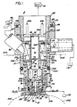
- FIGURE 1 illustrates a high pressure vortex injector 8 capable of fully atomizing and injecting fuel directly into a cylinder 202 of an engine generally shown as 204 in a full, conical spray pattern.
- the injector can also generate a hollow conical spray pattern.
- FIGURE 1 shows three embodiments of the invention, i.e. the preferred embodiment and two alternate embodiments. These alternate embodiments are directed to additional fuel carrying passages which communicate various parts of the injector to a drain and are more fully described below.
- the fuel injector 8 includes a housing 10 comprising of a upper bore 12 and a first passage 14 in communication therewith.
- An annular land 16 is situated proximate the bottom of the upper bore 12 about one end 18 of the passage 14.
- the upper bore 12 further includes an annular recess 20 formed at the bottom thereof about the land 16.
- the housing 10 further includes a stepped bore 30 situated at a second or other end 22 of the first passage 14.
- the stepped bore 30 includes a first and a second shoulder 32 and 34 respectively.
- a plurality of angled fluid passages 36a-e communicate the annual recess 20 with the upper extreme of the stepped bore 30. In the preferred embodiment of the invention, five such passages are used, it being understood that the number, size and angle of these passages 32 will vary with the specific application of the invention.
- a fuel inlet 38 is provided in the housing 10 to receive fuel and to communicate same to the upper bore 12 from a high pressure pump 40.
- the solenoid assembly 50 includes a bobbin 52 which comprises a hollow cylindrical member 54, an upper end 58a and a lower end 58b radially extending therefrom.
- An electric coil 60 is wound about the member 54 and is adapted to receive control signals generated by an ECU 55 through a plurality of terminals 62a and b. Typically the ECU will generate pulsed control signals. By varying the pulse width or duty cycle of these signals the conical spray pattern may vary such as from a fully filled pattern to a partially filled or hollow pattern.
- the second or lower end 58b of bobbin is adapted to be tightly received within the upper bore 12.
- the upper or first end 58a, as well as the exterior diameter of the electric coil 60, are of a smaller diameter than the diameter of the upper bore 12 to provide an annulus 64 between the solenoid assembly 50 and the upper bore to permit fuel to surround the electric coil 60 thereby cooling same.
- a metal stator 70 is received within the bobbin 52 and includes a top end 72 extending above the upper end 58a.
- the top end 72 of the stator 70 is receive within a blind bore 66 of an end cap 68.
- the cap 68 is received on a narrow shoulder 69 of the housing 10. This narrow shoulder in concert with the cap 68 provides a preferred reluctance path for magnetic flux and forms part of the magnetic circuit and provides for a hard metal contact therebetween. It can be shown that by using such a construction, upon activation of the coil 60, the stator 70 is desirably magnetically saturated.
- the housing and cap may be fabricated of steel (such as 430 FR). The securement of the stator 70 to the bobbin is more clearly shown by reference to FIGURES 2 and 3.
- FIGURES 2 and 3 show isolated plan views of the upper end 58a and lower end 58b respectively.
- the stator 70 is also shown.
- FIGURES 2 and 3 illustrate the outer surface of the member 54, shown in dotted line, about which the coil 60 is wound.
- the inner surface of the member 54 includes a plurality of radially directed ribs 210a, b and c.
- the ends 212a, b and c of the ribs 210a, b and c are arcuately shaped to receive and secure the stator 70 to the bobbin 52.
- the rib 210c is shown in FIGURE 1 and appears as a thickened portion of the left hand wall of the member 54.
- the solenoid assembly 50 further includes a armature assembly 74 comprising a low mass armature 76 which is loosely received within the first passage 14 and partially extends into the center of the bobbin 52 thereby improving the magnetic circuit formed between an interior portion 75 of the housing 10 and solenoid assembly.
- An upper end 77 of the armature 76 is spaced from the stator 70 thereby defining a working air gap 79. This gap 79 may typically be .097 mm (.0038 inches).
- the armature 76 and stator 70 may be of a highly magnetically permeable material such as silicon iron (Si Fe) and plated with a thin layer (.002 in., .05mm) of electrolus nickel or chrome to provide a hard, corrosion resistant, non-magnetic surface.
- the armature 76 includes a necked-down or narrow portion 78 for reducing the mass thereof.
- a rod or piston 80 extends from the armature 76.
- the rod 80 includes a first end 82 which preferably terminates in a spherically shaped valve 84.
- a second end 86 of the rod 80 may be press fit within a bore 88 of the armature 76.
- a spring 90 is positioned about the armature 76 and is located between a flanged end 92 thereof and the first shoulder 32 of the housing thereby urging the armature 76 outwardly relative to the stator 70.
- the injector 8 further includes an insert 100 comprising an axially extending cylindrical wall 102 open at one end 104.
- the insert 100 forms a substantially cup-like member which in concert with the housing 10 forms a fuel receiving chamber 116 in communication with the fluid passages 36a-e.
- Such chamber 116 provides a fuel reservoir or chamber for the pressurized fuel.
- the cylindrical wall 102 is tightly received within the stepped bore 30 and the open end 104 is forcably lodged against the second or larger diameter shoulder 34 of the housing 10.
- the insert 100 further includes a bottom element 106 integrally formed with the cylindrical wall 102 opposite the open end 104.
- the insert 100 includes a third passage 108 for guiding and for slidably receiving the rod or piston 80.
- the bottom element 106 forms a upper surface 110, interior to the stepped bore 30, and a generally concave protrusion 112 extending axially as part of a lower surface 114.
- the insert 100 further includes a plurality of non-intersecting fluid passages 120 a, b, and c which are more clearly shown in FIGURES 4a, 4b, 5a and 5b.
- the injector 8 further includes a valve seat 130 positioned below the bottom element 106 comprising a surface 132 which is spaced from and which is preferably conformal to the protrusion 112.
- the protrusion 112 is conical and the surface 132 is also conically shaped.
- the valve seat 130 further includes a metering orifice 134 preferably located at the nadir of the surface 132.
- the insert 100 and valve seat 130 are secured within the housing 10 by an end cap 128. As illustrated in FIGURE 1 the end cap 128 is threadably received onto the housing 10; however, such securement may be obtained by many equivalent known means. It can be appreciated that the end cap 128 can be fabricated as an integral portion of the housing 10.
- the injector 8 is loosely received within the cylinder 202 forming a narrow annulus 206 therebetween. After extended periods of operation carbon and other particulates will tend to accumulate in the annulus 206. If substantial amounts of carbon is deposited it makes removal of the injector 8 difficult if not impossible. It has been found that if the lower portion of the housing 10 such as the end cap 128 portion is coated with a polymer, such as a polymer in the family including polimide, Mylar and Teflon the injector can be easily withdrawn.
- a polymer such as a polymer in the family including polimide, Mylar and Teflon the injector can be easily withdrawn.
- the conically shaped space formed between the valve seat 130 and the projection 112 defines a swirl or vortex chamber 136 for receiving fuel relatively tangentially from the plurality of passages 120a-c and assists in swirling and rotationally acccelerating same prior to ejection through the metering orifice.
- the width or thickness of the vortex chamber 136 will be in the range of.076 mm (.003 in.) to 1.016 mm (.040 in.).
- the passages 120 extend from the upper surface 110 through to the lower surface 114. Such passages 120 may terminate at enlarged opening 122 proximate the surface 114.
- FIGURE 4a is a plan view of the insert 100 taken in isolation.
- FIGURE 5a is a cross-sectional view of the insert 100 taken through section 5a-5a of FIGURE 4a and more clearly illustrate the skewed angular orientation of the passages 120.
- the fluid passages 120a-c is oriented at a predetermined oblique angle relative to the axis 121 of the injector as well as to the surface 132 of the valve seat 130.
- the protrusion 112 is frusto-conically shaped having a angle of approximately 90° degrees.
- this angle may be varied within the range of 45° degrees to 150° degrees.
- the angle of the passages 120 is chosen such that fuel flows radially downward into the swirl chamber 136.
- the orientation of the passages 120 may be at 45 degrees to the axis 121 of the injector. It is not a requirement of the invention that the angle of each of the fluid passages 120a-c relative to the conical projection 112, surface 132 or axis 121 be equal.
- the preferred embodiment of the invention illustrates the utilization of a separate insert 100, it can be appreciated that the insert and its various components may be formed as an integral part of the housing 12.
- FIGURES 4b and 5b show an alternate embodiment of the insert 100.
- the passages 120 have been moved outwardly such that they terminate on a larger radius on the surface 114.
- the angle of these passages has also been increased to approximately 50 degrees. More specifically, the passages 120 terminate about a radius approxiomately equal to the radius of the shoulder 133 of the valve seat 130. In this manner fuel exiting the passages 120a, b, c flows over the shoulder 133 and is broken up or caused to flow turbulently in the swirl chamber. This added turbulence assists within the atomization of the fuel upon exit from the metering orifice 134.
- the top cap 68 includes a cylindrical cup-shaped element having a bottom 140 and cylindrical walls 142 extending therefrom.
- the cylindrical walls threadable engage the housing 10 and include a flanged end 144.
- a surface 146 of the flange end 144 is in contact with an end 147 of the housing and may include a grove 148 for securing an O-ring 150.
- the bottom 140 includes a plurality of openings 152a, b for receiving the terminals 62a and b.
- the terminals 62a and b extend through the bottom for securement to the ends of the electrical coils 60. Securement can be achieved by soldering or welding.
- the bottom 140 includes the blind bore 66 for receiving the top end 72 of the stator 70.
- the bottom 140 further includes a split angular ring 160 extending from the lower side thereof and positioned about of the stator 70 as more clearly shown in FIGURE 6, which is an isolated plan view of the cap 68. The ring 160 properly orients the bobbin.
- the bottom 140 Upon assembly of the cap 68 to the housing 10, the bottom 140 is positioned apart from the upper end 58a of the bobbin 52 thereby permitting fuel which is received within the annulus 64 to be communicated to the top portion of the bobbin.
- the bobbin 52 and stator 70 cooperate to form a plurality of a passages 56 a, b, c to communicate fuel therebetween.
- the passages 56 a, b, c are communicated to the fluid passages 36 a-e formed in the housing 10 and further enhance the cooling of the coil 60. Communication with the passages 36 a-e is achieved by forming a plurality of recesses or slots 164 a, b, c in the lower end 58b of the bobbin as shown in FIGURE 2.
- the fuel injector 8 has two operational conditions, one being an open condition and the other a closed condition.
- FIGURE 1 illustrates the fuel injector 8 in its closed condition wherein fuel is communicated from the inlet 38 to the annulus 64, through the passages 56 a, b, c the fluid passages 36 a-e and into the fuel chamber 116. Fuel is thereafter communicated through the fluid passages 120 a, b, c formed within the insert 100 to the vortex chamber 136.
- the fuel injector is designed to inject fuel directly into the cylinder of an internal combustion. This is accomplished by suppling fuel at a relatively high pressure, such as .69 ⁇ 107-1.38 ⁇ 107 N/m2 (1000-2000 psi) or higher.
- each of the various fluid carrying passages and chambers is pressurized to the input pressure. Fuel is prohibited from flowing through the metering orifice by virtue of the fact that the rod 80 and valve 84 formed thereon are positioned against a seating surface 135 of the valve seat 130 by the spring 90.
- an electrical signal such as a pulse width modulated control signal is applied to the electric coil 60 thereby repeatedly urging the armature 76 and rod 80 off from the valve seat 130.
- the rod 80 is moved off from the valve seat 130 pressurized fuel within the fuel chamber 116 flows through the fluid passages 120 against the surface 132 of the valve seat 130 thereby initiating a swirled flow.
- the swirling fluid is accelerated and exits the metering orifice in a spiral conical manner having a predefined exit cone. Simultaneous with the opening of the valve, the high pressure fuel within the fuel chamber 116 flows or, more specifically, leaks between the rod 80 and the third passage 108 and out through the metering orifice, thereby adding an axial component to the fuel flowing therefrom and assisting in the formation of a fully filled conical spray pattern.
- the leakage flow passed the rod 80 may be controlled by adding a seal between the insert 100 and the rod 80.
- FIGURE 1 illustrates alternate embodiments of the invention.
- One such alternate embodiment adds a outflow passage 170 to the housing 10.
- This passage 170 communicates the annulus 64 with a drain 172 thereby permitting a constant flow of fuel about the coil thereby further cooling the coil even during conditions when injector is closed.
- FIGURE 1 also illustrates another embodiment of the invention wherein another outflow passage 176 is provided in the valve seat 130 and cap 128 to communicate the swirl or vortex chamber 176 with the drain 172. In this manner the fuel residing in the vortex chamber is continuing swirling and upon opening of the metering orifice such swirling fluid is immediately ejected therefrom. Passages 170 and 176 need not be used together.
- the injector 8 may include an annular groove 220 and an O-ring 222 therein. Further, to control fuel leakage between the various mating parts of the injector 8, various other O-rings may be used.
- the insert 100 may include an annular groove 224 and O-ring 226.
- O-rings 230 and 232 may be provided between the insert 100 and the end cap 128 and the valve seat 130 and the end cap 128.
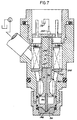
- FIGURE 7 illustrates another embodiment of the invention which provides for the continue flow of fuel within the vortex chamber 136.
- the passages 56 surrounding the stator 70 have been removed. This can be achieved by using a closely fitting cylindrical bobbin 52.
- An additional flow passage 240 is provided to communicate the angulus 64 with the passages 36 formed within the body 10.
- a seal 242 is provided to prohibit fuel from flowing from passage 240 into the solenoid assembly 50.
- the rod 80 and armature 74 are provide with an axial passage 244.
- the passage 244 does not extend throughout the entire length of the rod 80 but terminates at a cross-hole 246 immediately above the spherical valve surface 84. In this manner the cross-hole 246 is positioned as close as possible to the bottom of the swirl chamber 136.
- the stator 70 and cap 68 is also provided with an axial passage 248 which terminates at a fitting 250 which is communicated by a appropriate tubing to drain 172.
- fuel flows from annulus 64 through passages 240, 36 and 120 into the swirl chamber 136 wherein the fuel is permitted to swirl and achieve a maximum swirl rate before it is returned to drain through the passages 244, 246 and 248.
- the armature 74 is moved toward the stator 70 and the end 77 seats against an oppositely positioned surface 249 of the stator.
- the upward movement of the armature 74 seals passages 244 and 248 terminating communication therethrough.
Landscapes
- Engineering & Computer Science (AREA)
- Chemical & Material Sciences (AREA)
- Combustion & Propulsion (AREA)
- Mechanical Engineering (AREA)
- General Engineering & Computer Science (AREA)
- Physics & Mathematics (AREA)
- Electromagnetism (AREA)
- Fuel-Injection Apparatus (AREA)
Abstract
Description
- In order to shorten the time to vaporize fuel in a cyllinder of an engine it is desirable to introduce fuel having a very fine particle size. In addition, to reduce the levels of emissions in an engine, especially a two cycle engine, it is desirous to inject fuel directly into the cylinder. United States Patent 2,981,483 illustrates a low pressure fuel injector having a screw thread-like portion proximate its end. As the fuel flows through the helix of the thread it is rotated. The use of such a means to rotate or swirl the fuel does not yield a finely atomized spray and further such type of mechanism is expensive to manufacture. Patent abstracts of Japan, vol., no. 283(M-263) (1428), 16 December, 1983 and JP-A-58 158 367 illustrate a fuel injector defining a swirl chamber substantially spaced about a needle valve. Passages are formed through the needle valve and other parts of the injector to permit superfluous fuel to flow through the injector valve to cool an associated electromagnetic windings. GB-A-2 090 328 illustrates another fuel injector having a housing which includes a plurality of orifices spaced about a metering orifice. The combination thereof provides for a swirling and turbulant action of the fuel that enters the housing between the needle valve and the metering orifice.
- It is an object of the present invention to inject fuel directly into a cylinder of an engine in a defined swirl or vortex pattern. Another object of the invention is to provide an injector that can inject fuel in a fully filled or partially filled conical swirl pattern. It is yet another object of the invention to provide an injector having a vortex chamber and to continually circulate fuel therein when the injector is closed to enhance the rapid formation of the conical swirl pattern. Still another object of the invention is to provide an injector capable of injecting a variety of different types of fuels, i.e., gas, oil, keroseen etc.
- Accordingly, the invention comprises:
- A high pressure vortex fuel injector comprising a hollow housing including a plurality of passages at least one of which is adapted to receive fuel through an inlet. A valve seat is secured to the housing and includes a metering orifice and a first surface disposed directly upstream of the metering orifice. The injector also includes means for guiding the piston into seating relationship with the valve seat to control the flow of fuel through the metering orifice and means for moving the piston relative to the valve seat. The injector further includes means upstream of the metering orifice for forming a swirl or vortex chamber in cooperation with the first surface such that upon removal of the piston from the valve seat, fuel flows out from the metering orifice in a conical spiral manner and means for receiving pressurized fuel and for causing the fuel to enter the swirl chamber in an angular manner. More specifically the guide means includes a conically shaped second surface which in spaced from a similarly shaped first surface of the valve seat to form in cooperation therewith a constant dimension conical, angular swirl chamber. In addition, this guide means further includes a plurality of obliquely oriented straight passages extending through to the second surface and oriented at oblique angles relative to the first surface.
- The vortex chamber is so constructed to angularly accelerate the fuel as it flows toward the metering orifice. The injector additionally includes means for permitting fuel to circulate about an electric coil thereof, thereby cooling same during instances when the metering orifice is closed. The injector further includes means for assisting in the rapid formation of a conical spray pattern upon the opening of the metering orifice. Such means includes a flow passage immediately upsteam of a valve seating surface. The flow passage is returned to a drain. By locating the flow passage proximate the bottom of the swirl chamber the swirling fuel therein can achieve a large angular velocity even when the metering orifice is closed. Upon opening of the metering orifice this rapidly swirling fuel is immediately ejected forming the spray pattern.
- In the drawings:
- FIGURE 1 is a cross-sectional view of a fuel injector and illustrates a number of embodiments of the present invention.
- FIGURES 2 and 3 are plan views of various portions of a bobbin.
- FIGURE 4a is a plan view of an insert taken through section 4-4 of FIGURE 1 illustrating passages within an insert.
- FIGURE 5a is a cross-sectional view of the insert taken through section 5-5 of FIGURE 4.
- FIGURE 4b and 5b illustrate an alternate embodiment of the insert.
- FIGURE 6 illustrates an isolated plan view of an end cap.
- FIGURE 7 is another alternate embodiment of the invention.
- FIGURE 1 illustrates a high
pressure vortex injector 8 capable of fully atomizing and injecting fuel directly into acylinder 202 of an engine generally shown as 204 in a full, conical spray pattern. As will be seen below, subject to various minor modifications to the structure and method of control, the injector can also generate a hollow conical spray pattern. FIGURE 1 shows three embodiments of the invention, i.e. the preferred embodiment and two alternate embodiments. These alternate embodiments are directed to additional fuel carrying passages which communicate various parts of the injector to a drain and are more fully described below. Thefuel injector 8 includes ahousing 10 comprising of a upper bore 12 and a first passage 14 in communication therewith. Anannular land 16 is situated proximate the bottom of the upper bore 12 about one end 18 of the passage 14. The upper bore 12 further includes anannular recess 20 formed at the bottom thereof about theland 16. Thehousing 10 further includes astepped bore 30 situated at a second or other end 22 of the first passage 14. Thestepped bore 30 includes a first and asecond shoulder 32 and 34 respectively. A plurality of angled fluid passages 36a-e communicate theannual recess 20 with the upper extreme of thestepped bore 30. In the preferred embodiment of the invention, five such passages are used, it being understood that the number, size and angle of thesepassages 32 will vary with the specific application of the invention. Afuel inlet 38 is provided in thehousing 10 to receive fuel and to communicate same to the upper bore 12 from a high pressure pump 40. - Positioned within the upper bore 12 is a
solenoid assembly 50. Thesolenoid assembly 50 includes a bobbin 52 which comprises a hollowcylindrical member 54, anupper end 58a and a lower end 58b radially extending therefrom. Anelectric coil 60 is wound about themember 54 and is adapted to receive control signals generated by an ECU 55 through a plurality of terminals 62a and b. Typically the ECU will generate pulsed control signals. By varying the pulse width or duty cycle of these signals the conical spray pattern may vary such as from a fully filled pattern to a partially filled or hollow pattern. The second or lower end 58b of bobbin is adapted to be tightly received within the upper bore 12. The upper orfirst end 58a, as well as the exterior diameter of theelectric coil 60, are of a smaller diameter than the diameter of the upper bore 12 to provide anannulus 64 between thesolenoid assembly 50 and the upper bore to permit fuel to surround theelectric coil 60 thereby cooling same. - A
metal stator 70 is received within the bobbin 52 and includes a top end 72 extending above theupper end 58a. The top end 72 of thestator 70 is receive within ablind bore 66 of anend cap 68. Thecap 68, in turn, is received on anarrow shoulder 69 of thehousing 10. This narrow shoulder in concert with thecap 68 provides a preferred reluctance path for magnetic flux and forms part of the magnetic circuit and provides for a hard metal contact therebetween. It can be shown that by using such a construction, upon activation of thecoil 60, thestator 70 is desirably magnetically saturated. The housing and cap may be fabricated of steel (such as 430 FR). The securement of thestator 70 to the bobbin is more clearly shown by reference to FIGURES 2 and 3. - FIGURES 2 and 3 show isolated plan views of the
upper end 58a and lower end 58b respectively. In addition, for the purpose of illustration, thestator 70 is also shown. FIGURES 2 and 3 illustrate the outer surface of themember 54, shown in dotted line, about which thecoil 60 is wound. The inner surface of themember 54 includes a plurality of radially directed ribs 210a, b and c. Theends 212a, b and c of the ribs 210a, b and c are arcuately shaped to receive and secure thestator 70 to the bobbin 52. Therib 210c is shown in FIGURE 1 and appears as a thickened portion of the left hand wall of themember 54. With thestator 70 positioned within the bobbin 52, thestator 70, the interior wall of themember 54 and ribs 210a, b and c form a plurality offlow passages 56 a, b and c. Passage 56b is illustrated in FIGURE 1. - The
solenoid assembly 50 further includes aarmature assembly 74 comprising a lowmass armature 76 which is loosely received within the first passage 14 and partially extends into the center of the bobbin 52 thereby improving the magnetic circuit formed between an interior portion 75 of thehousing 10 and solenoid assembly. An upper end 77 of thearmature 76 is spaced from thestator 70 thereby defining a working air gap 79. This gap 79 may typically be .097 mm (.0038 inches). Thearmature 76 andstator 70 may be of a highly magnetically permeable material such as silicon iron (Si Fe) and plated with a thin layer (.002 in., .05mm) of electrolus nickel or chrome to provide a hard, corrosion resistant, non-magnetic surface. Thearmature 76 includes a necked-down ornarrow portion 78 for reducing the mass thereof. A rod orpiston 80 extends from thearmature 76. Therod 80 includes a first end 82 which preferably terminates in a spherically shapedvalve 84. A second end 86 of therod 80 may be press fit within a bore 88 of thearmature 76. A spring 90 is positioned about thearmature 76 and is located between aflanged end 92 thereof and thefirst shoulder 32 of the housing thereby urging thearmature 76 outwardly relative to thestator 70. - The
injector 8 further includes aninsert 100 comprising an axially extendingcylindrical wall 102 open at one end 104. As can be seen from FIGURE 1 theinsert 100 forms a substantially cup-like member which in concert with thehousing 10 forms a fuel receiving chamber 116 in communication with the fluid passages 36a-e. Such chamber 116 provides a fuel reservoir or chamber for the pressurized fuel. Thecylindrical wall 102 is tightly received within the stepped bore 30 and the open end 104 is forcably lodged against the second or larger diameter shoulder 34 of thehousing 10. Theinsert 100 further includes abottom element 106 integrally formed with thecylindrical wall 102 opposite the open end 104. Theinsert 100 includes a third passage 108 for guiding and for slidably receiving the rod orpiston 80. Thebottom element 106 forms aupper surface 110, interior to the stepped bore 30, and a generally concave protrusion 112 extending axially as part of alower surface 114. Theinsert 100 further includes a plurality of non-intersectingfluid passages 120 a, b, and c which are more clearly shown in FIGURES 4a, 4b, 5a and 5b. - The
injector 8 further includes avalve seat 130 positioned below thebottom element 106 comprising asurface 132 which is spaced from and which is preferably conformal to the protrusion 112. In the embodiment illustrated in FIGURE 1 the protrusion 112 is conical and thesurface 132 is also conically shaped. Thevalve seat 130 further includes ametering orifice 134 preferably located at the nadir of thesurface 132. Theinsert 100 andvalve seat 130 are secured within thehousing 10 by anend cap 128. As illustrated in FIGURE 1 theend cap 128 is threadably received onto thehousing 10; however, such securement may be obtained by many equivalent known means. It can be appreciated that theend cap 128 can be fabricated as an integral portion of thehousing 10. As illustrated in FIGURE 1 theinjector 8 is loosely received within thecylinder 202 forming anarrow annulus 206 therebetween. After extended periods of operation carbon and other particulates will tend to accumulate in theannulus 206. If substantial amounts of carbon is deposited it makes removal of theinjector 8 difficult if not impossible. It has been found that if the lower portion of thehousing 10 such as theend cap 128 portion is coated with a polymer, such as a polymer in the family including polimide, Mylar and Teflon the injector can be easily withdrawn. - The conically shaped space formed between the
valve seat 130 and the projection 112 defines a swirl or vortex chamber 136 for receiving fuel relatively tangentially from the plurality ofpassages 120a-c and assists in swirling and rotationally acccelerating same prior to ejection through the metering orifice. Typically, the width or thickness of the vortex chamber 136 will be in the range of.076 mm (.003 in.) to 1.016 mm (.040 in.). With reference to FIGURES 4a and 5a the passages 120 extend from theupper surface 110 through to thelower surface 114. Such passages 120 may terminate at enlarged opening 122 proximate thesurface 114. The diameter of the passages 120 may vary between .38 mm (0.15 inch) to.51 mm (.020 inch). FIGURE 4a is a plan view of theinsert 100 taken in isolation. FIGURE 5a is a cross-sectional view of theinsert 100 taken throughsection 5a-5a of FIGURE 4a and more clearly illustrate the skewed angular orientation of the passages 120. As can be seen of thefluid passages 120a-c is oriented at a predetermined oblique angle relative to theaxis 121 of the injector as well as to thesurface 132 of thevalve seat 130. In the embodiment of the invention shown in FIGURE 1 the protrusion 112 is frusto-conically shaped having a angle of approximately 90° degrees. It is felt that this angle may be varied within the range of 45° degrees to 150° degrees. Correspondingly, the angle of the passages 120 is chosen such that fuel flows radially downward into the swirl chamber 136. As an example, by using a projection 112 having an angle of 90 degrees the orientation of the passages 120 may be at 45 degrees to theaxis 121 of the injector. It is not a requirement of the invention that the angle of each of thefluid passages 120a-c relative to the conical projection 112,surface 132 oraxis 121 be equal. Further, while the preferred embodiment of the invention illustrates the utilization of aseparate insert 100, it can be appreciated that the insert and its various components may be formed as an integral part of the housing 12. - Reference is briefly made FIGURES 4b and 5b which show an alternate embodiment of the
insert 100. The passages 120 have been moved outwardly such that they terminate on a larger radius on thesurface 114. The angle of these passages has also been increased to approximately 50 degrees. More specifically, the passages 120 terminate about a radius approxiomately equal to the radius of theshoulder 133 of thevalve seat 130. In this manner fuel exiting thepassages 120a, b, c flows over theshoulder 133 and is broken up or caused to flow turbulently in the swirl chamber. This added turbulence assists within the atomization of the fuel upon exit from themetering orifice 134. - Reference is again made to FIGURE 1 and more particularly to the
top cap 68. Thetop cap 68 includes a cylindrical cup-shaped element having a bottom 140 andcylindrical walls 142 extending therefrom. The cylindrical walls threadable engage thehousing 10 and include aflanged end 144. A surface 146 of theflange end 144 is in contact with an end 147 of the housing and may include agrove 148 for securing an O-ring 150. The bottom 140 includes a plurality of openings 152a, b for receiving the terminals 62a and b. The terminals 62a and b extend through the bottom for securement to the ends of theelectrical coils 60. Securement can be achieved by soldering or welding. - The bottom 140 includes the blind bore 66 for receiving the top end 72 of the
stator 70. The bottom 140 further includes a splitangular ring 160 extending from the lower side thereof and positioned about of thestator 70 as more clearly shown in FIGURE 6, which is an isolated plan view of thecap 68. Thering 160 properly orients the bobbin. - Upon assembly of the
cap 68 to thehousing 10, the bottom 140 is positioned apart from theupper end 58a of the bobbin 52 thereby permitting fuel which is received within theannulus 64 to be communicated to the top portion of the bobbin. - A previously mentioned, the bobbin 52 and
stator 70 cooperate to form a plurality of apassages 56 a, b, c to communicate fuel therebetween. Thepassages 56 a, b, c are communicated to the fluid passages 36 a-e formed in thehousing 10 and further enhance the cooling of thecoil 60. Communication with the passages 36 a-e is achieved by forming a plurality of recesses or slots 164 a, b, c in the lower end 58b of the bobbin as shown in FIGURE 2. - The
fuel injector 8 has two operational conditions, one being an open condition and the other a closed condition. FIGURE 1 illustrates thefuel injector 8 in its closed condition wherein fuel is communicated from theinlet 38 to theannulus 64, through thepassages 56 a, b, c the fluid passages 36 a-e and into the fuel chamber 116. Fuel is thereafter communicated through thefluid passages 120 a, b, c formed within theinsert 100 to the vortex chamber 136. The fuel injector is designed to inject fuel directly into the cylinder of an internal combustion. This is accomplished by suppling fuel at a relatively high pressure, such as .69 · 10⁷-1.38 · 10⁷ N/m² (1000-2000 psi) or higher. During the closed mode of operation, each of the various fluid carrying passages and chambers is pressurized to the input pressure. Fuel is prohibited from flowing through the metering orifice by virtue of the fact that therod 80 andvalve 84 formed thereon are positioned against aseating surface 135 of thevalve seat 130 by the spring 90. When it is desired to enter the open mode of operation an electrical signal such as a pulse width modulated control signal is applied to theelectric coil 60 thereby repeatedly urging thearmature 76 androd 80 off from thevalve seat 130. As therod 80 is moved off from thevalve seat 130 pressurized fuel within the fuel chamber 116 flows through the fluid passages 120 against thesurface 132 of thevalve seat 130 thereby initiating a swirled flow. The swirling fluid is accelerated and exits the metering orifice in a spiral conical manner having a predefined exit cone. Simultaneous with the opening of the valve, the high pressure fuel within the fuel chamber 116 flows or, more specifically, leaks between therod 80 and the third passage 108 and out through the metering orifice, thereby adding an axial component to the fuel flowing therefrom and assisting in the formation of a fully filled conical spray pattern. The leakage flow passed therod 80 may be controlled by adding a seal between theinsert 100 and therod 80. - Reference is again made to FIGURE 1 which illustrates alternate embodiments of the invention. One such alternate embodiment adds a outflow passage 170 to the
housing 10. This passage 170 communicates theannulus 64 with adrain 172 thereby permitting a constant flow of fuel about the coil thereby further cooling the coil even during conditions when injector is closed. FIGURE 1 also illustrates another embodiment of the invention wherein anotheroutflow passage 176 is provided in thevalve seat 130 andcap 128 to communicate the swirl orvortex chamber 176 with thedrain 172. In this manner the fuel residing in the vortex chamber is continuing swirling and upon opening of the metering orifice such swirling fluid is immediately ejected therefrom.Passages 170 and 176 need not be used together. - In each of the above embodiments of the invention a substantial pressure differential exists across the
metering orifice 134, and as the fuel exits therefrom it is finely atomized. The spray pattern of the fuel is influenced somewhat by the L/D ratio of the metering orifice and may be varied as the application desires. - To facilitate securement to the walls of the engine's cylinder, the
injector 8 may include anannular groove 220 and an O-ring 222 therein. Further, to control fuel leakage between the various mating parts of theinjector 8, various other O-rings may be used. As an example, theinsert 100 may include anannular groove 224 and O-ring 226. In addition, O-rings 230 and 232 may be provided between theinsert 100 and theend cap 128 and thevalve seat 130 and theend cap 128. - FIGURE 7 illustrates another embodiment of the invention which provides for the continue flow of fuel within the vortex chamber 136. In this embodiment the
passages 56 surrounding thestator 70 have been removed. This can be achieved by using a closely fitting cylindrical bobbin 52. Anadditional flow passage 240 is provided to communicate theangulus 64 with the passages 36 formed within thebody 10. Aseal 242 is provided to prohibit fuel from flowing frompassage 240 into thesolenoid assembly 50. Therod 80 andarmature 74 are provide with an axial passage 244. The passage 244 does not extend throughout the entire length of therod 80 but terminates at a cross-hole 246 immediately above thespherical valve surface 84. In this manner the cross-hole 246 is positioned as close as possible to the bottom of the swirl chamber 136. Thestator 70 andcap 68 is also provided with anaxial passage 248 which terminates at a fitting 250 which is communicated by a appropriate tubing to drain 172. When theinjector 8 is closed fuel flows fromannulus 64 throughpassages 240, 36 and 120 into the swirl chamber 136 wherein the fuel is permitted to swirl and achieve a maximum swirl rate before it is returned to drain through thepassages coil 60 is activated thearmature 74 is moved toward thestator 70 and the end 77 seats against an oppositely positioned surface 249 of the stator. By virtue of the misaligned ofpassages 244 and 248 the upward movement of thearmature 74seals passages 244 and 248 terminating communication therethrough. As therod 80 is withdrawn from thevalve seat 130 fuel is ejected therefrom. In this manner upon the opening of the injector the fuel proximate themetering orifice 134 will have already achieved a substantial rotational volocity and exits therefrom immediately forming the conical spray pattern.
Claims (4)
a valve seat (130) secured to said housing (10), including a metering orifice (134), a first surface (132) surrounding said valve seat (130) and disposed directly upstream of said metering orifice;
guide means (108, 100) including a guide passage (108) therethrough for slidably receiving and for guiding a piston (80) into seating relationship with said valve seat (130) to control the flow of fuel through said metering orifice (134);
means (50) for moving said piston (80) relative to said valve seat (130) including a stator (70) and an electromagnetically movable armature (76), movable within a gap, substantially axially aligned with and movable relative to said stator;
means (120, 176, 246, 244, 248) for causing fuel flow within a swirl chamber (136) during instances when said injector is closed, said flow means including first passage means (120) which communicates with said inlet (38) and through which fuel is supplied to the swirl chamber (136), and second passage means (176, 246, 244, 248) which communicates said swirl chamber to a drain (172),
characterized in that the guide means (108, 100) includes a conically shaped second surface and said first surface (132) surrounding said valve seat (130) is similarly conically shaped and wherein the second surface of said guide means and the first surface (132) cooperate to form the annular swirl chamber (136) of constant dimensional conical shape such that upon removal of said piston (80) from said valve seat (130), fuel flows out from said metering orifice (134) in a conical manner and;
wherein the first passage means comprising a plurality of obliquely oriented straight passages (120) extending through said piston guide means (100) and second surface and oriented at oblique angles relative to the first surface (132) such that fuel exiting the plurality of passages (120) directly impacts the first surface (132) tangentially and is caused to flow within the swirl chamber (136) in a downward spiral manner towards the metering orifice (134).
Applications Claiming Priority (2)
| Application Number | Priority Date | Filing Date | Title |
|---|---|---|---|
| US92578086A | 1986-10-30 | 1986-10-30 | |
| US925780 | 1986-10-30 |
Publications (2)
| Publication Number | Publication Date |
|---|---|
| EP0328550A1 EP0328550A1 (en) | 1989-08-23 |
| EP0328550B1 true EP0328550B1 (en) | 1991-07-24 |
Family
ID=25452229
Family Applications (1)
| Application Number | Title | Priority Date | Filing Date |
|---|---|---|---|
| EP87907560A Expired - Lifetime EP0328550B1 (en) | 1986-10-30 | 1987-10-27 | Injector with swirl chamber return |
Country Status (6)
| Country | Link |
|---|---|
| EP (1) | EP0328550B1 (en) |
| JP (1) | JPH02501081A (en) |
| KR (1) | KR920010122B1 (en) |
| CA (1) | CA1302812C (en) |
| ES (1) | ES2005668A6 (en) |
| WO (1) | WO1988003226A1 (en) |
Cited By (1)
| Publication number | Priority date | Publication date | Assignee | Title |
|---|---|---|---|---|
| US6027050A (en) * | 1996-06-22 | 2000-02-22 | Robert Bosch Gmbh | Injection valve in particular for directly injecting fuel into the combustion chamber of an internal combustion engine |
Families Citing this family (1)
| Publication number | Priority date | Publication date | Assignee | Title |
|---|---|---|---|---|
| JP3478920B2 (en) * | 1996-02-14 | 2003-12-15 | 株式会社日立製作所 | In-cylinder fuel injection device and internal combustion engine equipped with the same |
Citations (1)
| Publication number | Priority date | Publication date | Assignee | Title |
|---|---|---|---|---|
| FR1535190A (en) * | 1966-08-27 | 1968-08-02 | Fuel injection installation for internal combustion combustion engines, and engines fitted with said installation |
Family Cites Families (8)
| Publication number | Priority date | Publication date | Assignee | Title |
|---|---|---|---|---|
| DE496000C (en) * | 1928-07-24 | 1930-08-27 | Motoren Werke Mannheim Ag | Nozzle for compressorless fuel injection in internal combustion engines |
| DE2460111A1 (en) * | 1974-04-13 | 1976-07-15 | Daimler Benz Ag | INJECTION VALVE |
| GB2090328B (en) * | 1978-02-07 | 1983-01-19 | Bendix Corp | A fuel injection assembly for an ic engine |
| DE2807052A1 (en) * | 1978-02-18 | 1979-08-23 | Bosch Gmbh Robert | ELECTROMAGNETIC FUEL INJECTION VALVE FOR COMBUSTION MACHINES |
| US4186883A (en) * | 1978-05-08 | 1980-02-05 | Essex Group, Inc. | Electromagnetic fuel injection valve with swirl means |
| JPS6042351B2 (en) * | 1978-11-07 | 1985-09-21 | 株式会社豊田中央研究所 | Reflux type volute injection valve |
| DE3437760A1 (en) * | 1984-10-16 | 1986-04-24 | Robert Bosch Gmbh, 7000 Stuttgart | FUEL INJECTION NOZZLE FOR INTERNAL COMBUSTION ENGINES |
| DE3516337A1 (en) * | 1985-05-07 | 1986-11-13 | Vdo Adolf Schindling Ag, 6000 Frankfurt | INJECTION VALVE |
-
1987
- 1987-10-27 WO PCT/US1987/002803 patent/WO1988003226A1/en not_active Ceased
- 1987-10-27 JP JP62507031A patent/JPH02501081A/en active Pending
- 1987-10-27 EP EP87907560A patent/EP0328550B1/en not_active Expired - Lifetime
- 1987-10-27 KR KR1019880700748A patent/KR920010122B1/en not_active Expired
- 1987-10-29 CA CA000550587A patent/CA1302812C/en not_active Expired - Lifetime
- 1987-10-30 ES ES8703111A patent/ES2005668A6/en not_active Expired
Patent Citations (1)
| Publication number | Priority date | Publication date | Assignee | Title |
|---|---|---|---|---|
| FR1535190A (en) * | 1966-08-27 | 1968-08-02 | Fuel injection installation for internal combustion combustion engines, and engines fitted with said installation |
Cited By (1)
| Publication number | Priority date | Publication date | Assignee | Title |
|---|---|---|---|---|
| US6027050A (en) * | 1996-06-22 | 2000-02-22 | Robert Bosch Gmbh | Injection valve in particular for directly injecting fuel into the combustion chamber of an internal combustion engine |
Also Published As
| Publication number | Publication date |
|---|---|
| ES2005668A6 (en) | 1989-03-16 |
| KR880701827A (en) | 1988-11-05 |
| CA1302812C (en) | 1992-06-09 |
| EP0328550A1 (en) | 1989-08-23 |
| WO1988003226A1 (en) | 1988-05-05 |
| KR920010122B1 (en) | 1992-11-16 |
| JPH02501081A (en) | 1990-04-12 |
Similar Documents
| Publication | Publication Date | Title |
|---|---|---|
| EP0359737B1 (en) | High pressure vortex injector | |
| US4805837A (en) | Injector with swirl chamber return | |
| US5108037A (en) | Fuel injection valve | |
| US7299997B2 (en) | Fuel injector with sauter-mean-diameter atomization spray of less than 70 microns | |
| KR100342093B1 (en) | A swirl generator in a fuel injector | |
| EP1236888B1 (en) | Fluid injection nozzle | |
| KR100282108B1 (en) | Fuel injection valve | |
| EP1042604B1 (en) | Flat needle for pressurized swirl fuel injector | |
| CA1132417A (en) | Electromagnetic fuel injector | |
| EP1392968B1 (en) | Spray pattern control with non-angled orifices in fuel injection metering disc | |
| US20040056114A1 (en) | Spray pattern control with angular orientation in fuel injector and method | |
| US4634055A (en) | Injection valve with upstream internal metering | |
| EP0042799A2 (en) | Electromagnetic fuel injector | |
| JPH07189868A (en) | Electromagnetically operated injection valve | |
| CA1302812C (en) | Injector with swirl chamber return | |
| US20060157595A1 (en) | Fuel injector for high fuel flow rate applications | |
| JP2004511719A (en) | Fuel injection valve | |
| EP1482170B1 (en) | Injection nozzle with an improved injection function and method for producing an injection nozzle | |
| JPH02125957A (en) | Electromagnetic type fuel injection valve | |
| JPH03275976A (en) | Fuel injection valve | |
| JPH07174058A (en) | Electromagnetic fuel injection valve | |
| JPH0979108A (en) | Fuel injection valve | |
| JPH01178763A (en) | Solenoid-controlled fuel injection valve |
Legal Events
| Date | Code | Title | Description |
|---|---|---|---|
| PUAI | Public reference made under article 153(3) epc to a published international application that has entered the european phase |
Free format text: ORIGINAL CODE: 0009012 |
|
| 17P | Request for examination filed |
Effective date: 19890418 |
|
| AK | Designated contracting states |
Kind code of ref document: A1 Designated state(s): DE FR GB IT |
|
| 17Q | First examination report despatched |
Effective date: 19891027 |
|
| RAP1 | Party data changed (applicant data changed or rights of an application transferred) |
Owner name: SIEMENS AKTIENGESELLSCHAFT |
|
| GRAA | (expected) grant |
Free format text: ORIGINAL CODE: 0009210 |
|
| AK | Designated contracting states |
Kind code of ref document: B1 Designated state(s): DE FR GB IT |
|
| REF | Corresponds to: |
Ref document number: 3771727 Country of ref document: DE Date of ref document: 19910829 |
|
| ET | Fr: translation filed | ||
| ITF | It: translation for a ep patent filed | ||
| PLBE | No opposition filed within time limit |
Free format text: ORIGINAL CODE: 0009261 |
|
| STAA | Information on the status of an ep patent application or granted ep patent |
Free format text: STATUS: NO OPPOSITION FILED WITHIN TIME LIMIT |
|
| 26N | No opposition filed | ||
| PGFP | Annual fee paid to national office [announced via postgrant information from national office to epo] |
Ref country code: DE Payment date: 19931216 Year of fee payment: 7 |
|
| PGFP | Annual fee paid to national office [announced via postgrant information from national office to epo] |
Ref country code: GB Payment date: 19940916 Year of fee payment: 8 |
|
| PGFP | Annual fee paid to national office [announced via postgrant information from national office to epo] |
Ref country code: FR Payment date: 19941024 Year of fee payment: 8 |
|
| PG25 | Lapsed in a contracting state [announced via postgrant information from national office to epo] |
Ref country code: DE Effective date: 19950701 |
|
| PG25 | Lapsed in a contracting state [announced via postgrant information from national office to epo] |
Ref country code: GB Effective date: 19951027 |
|
| GBPC | Gb: european patent ceased through non-payment of renewal fee |
Effective date: 19951027 |
|
| PG25 | Lapsed in a contracting state [announced via postgrant information from national office to epo] |
Ref country code: FR Effective date: 19960628 |
|
| REG | Reference to a national code |
Ref country code: FR Ref legal event code: ST |
|
| PG25 | Lapsed in a contracting state [announced via postgrant information from national office to epo] |
Ref country code: IT Free format text: LAPSE BECAUSE OF NON-PAYMENT OF DUE FEES Effective date: 20051027 |