EP0327617B1 - Improvements relating to noise reduction systems - Google Patents
Improvements relating to noise reduction systems Download PDFInfo
- Publication number
- EP0327617B1 EP0327617B1 EP88905991A EP88905991A EP0327617B1 EP 0327617 B1 EP0327617 B1 EP 0327617B1 EP 88905991 A EP88905991 A EP 88905991A EP 88905991 A EP88905991 A EP 88905991A EP 0327617 B1 EP0327617 B1 EP 0327617B1
- Authority
- EP
- European Patent Office
- Prior art keywords
- filter
- filter means
- high pass
- loop
- microphone
- Prior art date
- Legal status (The legal status is an assumption and is not a legal conclusion. Google has not performed a legal analysis and makes no representation as to the accuracy of the status listed.)
- Expired - Lifetime
Links
- 230000009467 reduction Effects 0.000 title claims abstract description 9
- 230000010363 phase shift Effects 0.000 claims abstract description 20
- 238000012546 transfer Methods 0.000 claims abstract description 13
- 235000021170 buffet Nutrition 0.000 claims abstract description 4
- 238000001914 filtration Methods 0.000 claims description 6
- 230000006641 stabilisation Effects 0.000 claims description 6
- 230000003019 stabilising effect Effects 0.000 claims description 2
- 238000010586 diagram Methods 0.000 description 6
- 230000005534 acoustic noise Effects 0.000 description 4
- 239000003990 capacitor Substances 0.000 description 4
- 230000007423 decrease Effects 0.000 description 3
- 230000000694 effects Effects 0.000 description 3
- 101100460844 Mus musculus Nr2f6 gene Proteins 0.000 description 2
- 230000003321 amplification Effects 0.000 description 2
- 230000002238 attenuated effect Effects 0.000 description 2
- 230000008859 change Effects 0.000 description 2
- 238000012937 correction Methods 0.000 description 2
- 238000013461 design Methods 0.000 description 2
- 238000011835 investigation Methods 0.000 description 2
- 238000003199 nucleic acid amplification method Methods 0.000 description 2
- 238000012545 processing Methods 0.000 description 2
- 230000004044 response Effects 0.000 description 2
- 230000000630 rising effect Effects 0.000 description 2
- 230000008901 benefit Effects 0.000 description 1
- 230000001364 causal effect Effects 0.000 description 1
- 230000001419 dependent effect Effects 0.000 description 1
- 239000002360 explosive Substances 0.000 description 1
- 230000000087 stabilizing effect Effects 0.000 description 1
Images



Classifications
-
- G—PHYSICS
- G10—MUSICAL INSTRUMENTS; ACOUSTICS
- G10K—SOUND-PRODUCING DEVICES; METHODS OR DEVICES FOR PROTECTING AGAINST, OR FOR DAMPING, NOISE OR OTHER ACOUSTIC WAVES IN GENERAL; ACOUSTICS NOT OTHERWISE PROVIDED FOR
- G10K11/00—Methods or devices for transmitting, conducting or directing sound in general; Methods or devices for protecting against, or for damping, noise or other acoustic waves in general
- G10K11/16—Methods or devices for protecting against, or for damping, noise or other acoustic waves in general
- G10K11/175—Methods or devices for protecting against, or for damping, noise or other acoustic waves in general using interference effects; Masking sound
- G10K11/178—Methods or devices for protecting against, or for damping, noise or other acoustic waves in general using interference effects; Masking sound by electro-acoustically regenerating the original acoustic waves in anti-phase
- G10K11/1785—Methods, e.g. algorithms; Devices
- G10K11/17853—Methods, e.g. algorithms; Devices of the filter
-
- G—PHYSICS
- G10—MUSICAL INSTRUMENTS; ACOUSTICS
- G10K—SOUND-PRODUCING DEVICES; METHODS OR DEVICES FOR PROTECTING AGAINST, OR FOR DAMPING, NOISE OR OTHER ACOUSTIC WAVES IN GENERAL; ACOUSTICS NOT OTHERWISE PROVIDED FOR
- G10K11/00—Methods or devices for transmitting, conducting or directing sound in general; Methods or devices for protecting against, or for damping, noise or other acoustic waves in general
- G10K11/16—Methods or devices for protecting against, or for damping, noise or other acoustic waves in general
- G10K11/175—Methods or devices for protecting against, or for damping, noise or other acoustic waves in general using interference effects; Masking sound
- G10K11/178—Methods or devices for protecting against, or for damping, noise or other acoustic waves in general using interference effects; Masking sound by electro-acoustically regenerating the original acoustic waves in anti-phase
- G10K11/1781—Methods or devices for protecting against, or for damping, noise or other acoustic waves in general using interference effects; Masking sound by electro-acoustically regenerating the original acoustic waves in anti-phase characterised by the analysis of input or output signals, e.g. frequency range, modes, transfer functions
- G10K11/17821—Methods or devices for protecting against, or for damping, noise or other acoustic waves in general using interference effects; Masking sound by electro-acoustically regenerating the original acoustic waves in anti-phase characterised by the analysis of input or output signals, e.g. frequency range, modes, transfer functions characterised by the analysis of the input signals only
- G10K11/17825—Error signals
-
- G—PHYSICS
- G10—MUSICAL INSTRUMENTS; ACOUSTICS
- G10K—SOUND-PRODUCING DEVICES; METHODS OR DEVICES FOR PROTECTING AGAINST, OR FOR DAMPING, NOISE OR OTHER ACOUSTIC WAVES IN GENERAL; ACOUSTICS NOT OTHERWISE PROVIDED FOR
- G10K11/00—Methods or devices for transmitting, conducting or directing sound in general; Methods or devices for protecting against, or for damping, noise or other acoustic waves in general
- G10K11/16—Methods or devices for protecting against, or for damping, noise or other acoustic waves in general
- G10K11/175—Methods or devices for protecting against, or for damping, noise or other acoustic waves in general using interference effects; Masking sound
- G10K11/178—Methods or devices for protecting against, or for damping, noise or other acoustic waves in general using interference effects; Masking sound by electro-acoustically regenerating the original acoustic waves in anti-phase
- G10K11/1787—General system configurations
- G10K11/17875—General system configurations using an error signal without a reference signal, e.g. pure feedback
-
- G—PHYSICS
- G10—MUSICAL INSTRUMENTS; ACOUSTICS
- G10K—SOUND-PRODUCING DEVICES; METHODS OR DEVICES FOR PROTECTING AGAINST, OR FOR DAMPING, NOISE OR OTHER ACOUSTIC WAVES IN GENERAL; ACOUSTICS NOT OTHERWISE PROVIDED FOR
- G10K11/00—Methods or devices for transmitting, conducting or directing sound in general; Methods or devices for protecting against, or for damping, noise or other acoustic waves in general
- G10K11/16—Methods or devices for protecting against, or for damping, noise or other acoustic waves in general
- G10K11/175—Methods or devices for protecting against, or for damping, noise or other acoustic waves in general using interference effects; Masking sound
- G10K11/178—Methods or devices for protecting against, or for damping, noise or other acoustic waves in general using interference effects; Masking sound by electro-acoustically regenerating the original acoustic waves in anti-phase
- G10K11/1787—General system configurations
- G10K11/17885—General system configurations additionally using a desired external signal, e.g. pass-through audio such as music or speech
-
- G—PHYSICS
- G10—MUSICAL INSTRUMENTS; ACOUSTICS
- G10K—SOUND-PRODUCING DEVICES; METHODS OR DEVICES FOR PROTECTING AGAINST, OR FOR DAMPING, NOISE OR OTHER ACOUSTIC WAVES IN GENERAL; ACOUSTICS NOT OTHERWISE PROVIDED FOR
- G10K2210/00—Details of active noise control [ANC] covered by G10K11/178 but not provided for in any of its subgroups
- G10K2210/10—Applications
- G10K2210/108—Communication systems, e.g. where useful sound is kept and noise is cancelled
- G10K2210/1081—Earphones, e.g. for telephones, ear protectors or headsets
-
- G—PHYSICS
- G10—MUSICAL INSTRUMENTS; ACOUSTICS
- G10K—SOUND-PRODUCING DEVICES; METHODS OR DEVICES FOR PROTECTING AGAINST, OR FOR DAMPING, NOISE OR OTHER ACOUSTIC WAVES IN GENERAL; ACOUSTICS NOT OTHERWISE PROVIDED FOR
- G10K2210/00—Details of active noise control [ANC] covered by G10K11/178 but not provided for in any of its subgroups
- G10K2210/30—Means
- G10K2210/301—Computational
- G10K2210/3028—Filtering, e.g. Kalman filters or special analogue or digital filters
-
- G—PHYSICS
- G10—MUSICAL INSTRUMENTS; ACOUSTICS
- G10K—SOUND-PRODUCING DEVICES; METHODS OR DEVICES FOR PROTECTING AGAINST, OR FOR DAMPING, NOISE OR OTHER ACOUSTIC WAVES IN GENERAL; ACOUSTICS NOT OTHERWISE PROVIDED FOR
- G10K2210/00—Details of active noise control [ANC] covered by G10K11/178 but not provided for in any of its subgroups
- G10K2210/30—Means
- G10K2210/301—Computational
- G10K2210/3039—Nonlinear, e.g. clipping, numerical truncation, thresholding or variable input and output gain
-
- G—PHYSICS
- G10—MUSICAL INSTRUMENTS; ACOUSTICS
- G10K—SOUND-PRODUCING DEVICES; METHODS OR DEVICES FOR PROTECTING AGAINST, OR FOR DAMPING, NOISE OR OTHER ACOUSTIC WAVES IN GENERAL; ACOUSTICS NOT OTHERWISE PROVIDED FOR
- G10K2210/00—Details of active noise control [ANC] covered by G10K11/178 but not provided for in any of its subgroups
- G10K2210/30—Means
- G10K2210/301—Computational
- G10K2210/3045—Multiple acoustic inputs, single acoustic output
Definitions
- This invention relates to systems for reducing the level of acoustic noise fields within ear-defenders or earphone structures worn by personnel (e.g., pilots, vehicle drivers, military personnel) in high noise environments.
- personnel e.g., pilots, vehicle drivers, military personnel
- noise pick-up microphones and noise-cancelling sound generators (usually known as loudspeakers) mounted within the internal cavities or enclosures of the respective ear-defenders.
- the noise pick-up microphones produce electrical signal outputs in response to the acoustic noise fields within the cavities and these signal outputs are phase inverted, filtered and amplified in a feedback loop and fed to the noise-cancelling sound generators which produce noise-cancelling acoustic signals of substantially the same amplitude but of opposite phase to the acoustic noise field waveforms.
- a further problem which occurs is that due to the imperfect transfer functions of both the microphone and generator, the total bandwidth for feedback signals having an appropriate phase is limited, being bounded by regions in which positive feedback occurs. It is usual to employ in feedback systems in general a lowpass first order filter operating at a high frequency in order to stabilize the loop. However such first order low pass filters are not appropriate for filtering out sound energy frequencies in ANR systems because of the large phase changes which occur in the cut-off regions which give rise to problems of positive feedback and signal enhancement.
- an active noise reduction system comprising a noise-cancelling sound generator, a microphone acoustically coupled to said generator, a feedback loop connected between said microphone and said generator, and including loop stabilisation means for inverting the phase of microphone signals and filtering the microphone signals, means for amplifying the phase inverted and filtered signals, and a first high pass frequency filter means for filtering out sound energy from high pressure sound pulses arising from low frequency buffets, characterised in that the first filter means has a gain characteristic which is relatively low in a first frequency band and then rises continuously to a relatively high value in a second frequency band, said first filter means introducing a phase shift which rises to a maximum value in a transitional region of said gain characteristic of said first high pass frequency filter means, said system further comprising a second high pass filter means coupled between the loop stabilising means and the amplifying means for increasing loop gain and/or adjusting phase shift by predetermined amounts within one or more predetermined frequency bands, wherein the second filter means has a gain characteristic which
- this aspect of the invention is based on the recognition that the major part of sound energy in high pressure pulses is present at low frequencies say below 100 Hz and thus the provision of low frequency filter means in the feedback loop can reduce a major part of the sound energy in the pulses.
- filter means is conveniently referred to as an anti-buffet filter (ABF).
- ABSF anti-buffet filter
- the filter means referred to above may be used in conjunction with a voltage limiting means, which prevents the generator from being overdriven by amplification of high pressure sound pulses.
- a voltage limiting means may comprise a non-linear amplifier or zener diode arrangement.
- second filter means increasing gain or adjusting phase shift, preferably both, prevents enhancement of the signal in the feedback loop arising from imperfect transfer functions of the microphone and generator.
- the further filter means is conveniently termed an anti-enhancement filter (AEF).
- AEF anti-enhancement filter
- This further aspect of the invention is based on our discovery that enhancement problems caused by transducer imperfections arise in a frequency region centred at about 500 Hz where the gain decreases whereas the phase lag in this area increases to about 3 ⁇ /2.
- a high pass filter which adjusts the gain in this region whilst providing a phase advance compensating phase shift can significantly reduce the problems of signal enhancement.
- the preferred speech signals are injected at a single point in the feedback loop between the AEF and the amplifying means, in order that the speech signals are substantially uncoloured by the AEF and other filters. It will be understood that the speech signals are in a frequency range which is for the most part above the frequency range in which the ANR is operative and the speech signals are not therefore reduced. They may however be affected by higher frequency filters in the feedback loop.
- the active noise reduction system illustrated comprises a generally cup-shaped circumaural earphone structure 1 arranged to enclose the wearer's ear 2.
- the rim of the structure 1 is cushioned against the side of the wearer's head 3 by means of a compliant ring cushion 4.
- the earphone structure 1 embodies a small noise pick-up microphone 5, which detects the noise within the earphone adjacent to the wearer's ear 2 and provides an electrical output dependent upon the detected noise.
- This output signal from the microphone is passed through an anti-buffet filter 6, a loop stabilisation unit 7,a low-pass filter 8, an anti-enhancement filter 10 and amplifier 12, to a noise cancelling sound generator (loudspeaker) 14 which is mounted on a baffle 16 within structure 1.
- Loop stabilisation unit 7 includes a phase inverter 72, a loop stabilizing filter 74 (which may be incorporated in low-pass filter 8 as in Figure 6) for filtering out very high frequencies, and a voltage limiting circuit 76 comprising a zener diode switching arrangement for limiting high amplitude input signals.
- Filter 6 is placed first in the feedback loop in order to minimise signal values in the loop.
- the effect of the anti-enhancement filter is to reduce noise effects arising from imperfect transfer functions of microphone 5 and generator 14.
- a speech signal is injected between anti-enhancement filter 10 and amplifier 12 at an input node 18.
- the introduction of the speech signal at this point allows the speech signal to be substantially uncoloured by the loop filters.
- the speech signals may be pre-emphasised by amplification where they may be attenuated by the ANR system.
- the ABF 6 comprises an amplifier 20 having a negative feedback loop with a resistor R1 connected to its inverting input, which receives an input signal from a resistive/capacitive network R2, R3, C1.
- the non-inverting input of the amplifier is connected through a resistor R4 to ground.
- ABF 6 The characteristics of ABF 6 are shown in Figure 3, whence it may be seen that the filter has a loss factor of about 8db up to about 100 Hz at which frequency the loss reduces continuously until at about 500Hz the filter exhibits a small gain factor.
- the phase shift introduced by the filter is an advance with increasing frequency rising in the transitional region from the base level of substantially 180° (the filter includes an inverting amplifier) to a maximum at about 200 Hz of about 215°. This phase shift must be taken into account when considering the overall loop stability.
- the effect of the ABF 6 on the overall feedback loop transfer function is to attenuate the low frequency end of the function whereby noise in the frequency range up to 200Hz is severely attenuated.
- AEF The preferred form of AEF is shown in Figure 4 as comprising two cascaded stages 21, 22, each stage comprising an amplifier 24 with a resistor R1 in a negative feedback loop and with the inverting amplifier input being connected to ground via the series combination of a resistor R2 and capacitor C1.
- the filter characteristics are shown in Figure 5 with the gain having step-form, being roughly 0db up to 100 Hz and then rising to 10db gain at 1 kHz.
- the phase shift, a phase advance with increasing frequency rises in the region in which the gain changes, from a base level of substantially 0° a maximum value of 25° at roughly 500 Hz.
- the gain reduces to a minimum value at about 500 Hz whereas the phase shift in this area rises to a maximum of about more than 3 ⁇ /2.
- the transfer functions are modified in this area to reduce phase shift and increase gain, thereby reducing signal enhancement.
- a circuit diagram of low pass filter 8 is shown in Figure 6 as comprising a transitional second order filter including an amplifier 60 having a non-inverting input connected to a filter input via resistors R1, R2 and a capacitor C1 coupled between the amplifier input and ground.
- Two feedback loops are provided from the amplifier output to the non-inverting input: a first loop including a capacitor C2 and a second loop comprising resistors R3, R4, R5 and a capacitor C3 in series with a resistor R9 connected between resistors R4, R5 and ground.
- a further feedback loop is provided comprising a resistor R7 connected between the amplifier output and the inverting amplifier input.
- a further resistor R8 is connected between resistor R7 and ground.
- the characteristics of the filter are shown in Figure 7 where the gain is close to 0db up to about 1000Hz and is about -30db around 10,000Hz. The gain decreases between these regions relatively quickly in a cut-off region.
- the phase shift across the filter is roughly 150°, (the filter includes a non-inverting amplifier) in the region below 1,000Hz and above 10,000Hz, but decreases to a minimum, (a phase lag with increasing frequency) of about 45° in the centre of the cut-off region.
- a phase change of roughly 105° is acceptable and is much smaller than 180 degrees resulting from a conventional second order low-pass filter.
- a second order filter is shown, the filter could be a higher or lower order if desired.
- a high pass filter which combines the functions of the AEF and ABF and is herein referred to as an ABEF.
- the filter is a second order filter comprising two filter sections connected in cascade, the filter sections being identical. (If desired a first order filter could be employed).
- Each filter section comprises an input port 80 coupled to the inverting input of an amplifier 82 through a resistance R1 connected in parallel with a capacitance C1 and a resistance R2.
- the non-inverting input of the amplifier is connected to ground via a resistance R3, and the output of the amplifier 86 is connected in a negative feedback loop to the inverting input of the amplifier via a resistor R4.
- the gain is slightly greater than 0db up to about 500 Hz and then rises to about 10db at a frequency of 2 kHz in a transitional region between 500Hz-2kHz.
- the phase shift changes from a constant level of about 0° to a maximum value of substantially 60° at about 1 kHz.
- the filters shown may be replaced by digital filters, and the elements of the feedback loop may be digitised by employing a micro-computer with appropriate routines.
- the invention claimed is intended to cover both analog and digital systems.
Landscapes
- Physics & Mathematics (AREA)
- Engineering & Computer Science (AREA)
- Acoustics & Sound (AREA)
- Multimedia (AREA)
- Health & Medical Sciences (AREA)
- Audiology, Speech & Language Pathology (AREA)
- General Health & Medical Sciences (AREA)
- Soundproofing, Sound Blocking, And Sound Damping (AREA)
- Electroluminescent Light Sources (AREA)
- Gas-Filled Discharge Tubes (AREA)
- Networks Using Active Elements (AREA)
- Exhaust Silencers (AREA)
- Noise Elimination (AREA)
Abstract
Description
- This invention relates to systems for reducing the level of acoustic noise fields within ear-defenders or earphone structures worn by personnel (e.g., pilots, vehicle drivers, military personnel) in high noise environments.
- Known active noise reduction (ANR) systems for reducing the acoustic noise field in ear-defenders comprise noise pick-up microphones and noise-cancelling sound generators (usually known as loudspeakers) mounted within the internal cavities or enclosures of the respective ear-defenders. The noise pick-up microphones produce electrical signal outputs in response to the acoustic noise fields within the cavities and these signal outputs are phase inverted, filtered and amplified in a feedback loop and fed to the noise-cancelling sound generators which produce noise-cancelling acoustic signals of substantially the same amplitude but of opposite phase to the acoustic noise field waveforms. The design considerations underlying such ANR systems are described in "Some transducer design considerations for earphone active noise reduction systems", Twiney et al., Vol. 7 part 2. pp.95-102, Proc. Spring Conference, 1985, York, Institute of Acoustics. A specific arrangement of an ANR-system is disclosed, for example, in EP-A-0 212 840.
- Problems arise through inherent imperfections in the pick-up microphones and sound generators, by way of unwanted phase changes producing signal enhancement or by way of failure to cope with large amplitude signals in certain frequency regions.
- One problem which occurs is that of large pressure pulses (buffets) which occur inside an ear-defender or earphone structure due to relative movement between the human head and the earphone, or propagate to the earphone from a device that causes a rapid pressure change, e.g. a gun, helicopter, vehicle, explosive device. These pulses are very high in amplitude, and create large signals in the feedback loop as a result of high system loop gain. Due to the inadequacy of the sound generator to produce enough sound output, drive voltages appear at the sound generators which are higher than the maximum input voltage, and may overdrive the sound generator and cause permanent failure.
- Another problem which arises is that of signal enhancement at certain frequencies within the bandwidth of the feedback loop wherein due to imperfect transfer functions of the noise pickup microphone and sound generator the ANR will, at certain frequencies be feeding in-phase(i.e. positive feedback) signals rather than anti-phase(i.e. negative feedback) signals to the sound generator.
- A further problem which occurs is that due to the imperfect transfer functions of both the microphone and generator, the total bandwidth for feedback signals having an appropriate phase is limited, being bounded by regions in which positive feedback occurs. It is usual to employ in feedback systems in general a lowpass first order filter operating at a high frequency in order to stabilize the loop. However such first order low pass filters are not appropriate for filtering out sound energy frequencies in ANR systems because of the large phase changes which occur in the cut-off regions which give rise to problems of positive feedback and signal enhancement.
- It was previously thought, as appears from the article referred to above, that electronic processing to overcome problems in ANR systems had limited application because of the causal relation between amplitude and phase response of electronic filters.
- Nevertheless it has now been found as a result of careful investigation into the problems arising in feedback loops of ANR systems, that electronic processing may be used to advantage.
- It is an object of the present invention to overcome one or more of the above problems.
- According to the present invention there is provided an active noise reduction system comprising a noise-cancelling sound generator, a microphone acoustically coupled to said generator, a feedback loop connected between said microphone and said generator, and including loop stabilisation means for inverting the phase of microphone signals and filtering the microphone signals, means for amplifying the phase inverted and filtered signals, and a first high pass frequency filter means for filtering out sound energy from high pressure sound pulses arising from low frequency buffets, characterised in that the first filter means has a gain characteristic which is relatively low in a first frequency band and then rises continuously to a relatively high value in a second frequency band, said first filter means introducing a phase shift which rises to a maximum value in a transitional region of said gain characteristic of said first high pass frequency filter means, said system further comprising a second high pass filter means coupled between the loop stabilising means and the amplifying means for increasing loop gain and/or adjusting phase shift by predetermined amounts within one or more predetermined frequency bands, wherein the second filter means has a gain characteristic which is relatively low in a first frequency band and then rises continuously to a relatively high value in a second frequency band, the phase shift introduced by the second filter means rises to a maximum value in the transitional region of filter gain characteristic.
- Thus this aspect of the invention is based on the recognition that the major part of sound energy in high pressure pulses is present at low frequencies say below 100 Hz and thus the provision of low frequency filter means in the feedback loop can reduce a major part of the sound energy in the pulses. Such filter means is conveniently referred to as an anti-buffet filter (ABF). The amount of ABF correction is limited because stability of the feedback loop must be maintained, the total loop gain being kept below unity where the total phase shift may cause constructive interference.
- The filter means referred to above may be used in conjunction with a voltage limiting means, which prevents the generator from being overdriven by amplification of high pressure sound pulses. Such voltage limiting means may comprise a non-linear amplifier or zener diode arrangement.
- Thus in accordance with the invention, the provision of second filter means increasing gain or adjusting phase shift, preferably both, prevents enhancement of the signal in the feedback loop arising from imperfect transfer functions of the microphone and generator. The further filter means is conveniently termed an anti-enhancement filter (AEF). The amount of AEF correction is limited by the need to maintain stability of the feedback loop (the total loop gain must be kept below unity when the total phase shift may cause constructive interference).
- This further aspect of the invention is based on our discovery that enhancement problems caused by transducer imperfections arise in a frequency region centred at about 500 Hz where the gain decreases whereas the phase lag in this area increases to about 3π/2. Thus a high pass filter which adjusts the gain in this region whilst providing a phase advance compensating phase shift can significantly reduce the problems of signal enhancement.
- In a particularly preferred form of the invention, it has been discovered as a result of careful investigation into the operability of ANR systems that the functions of the ABF and AEF, which operate at different frequencies and with different transfer functions can be accomplished by the use of a single high pass filter (ABEF) for attenuating frequencies below a predetermined frequency, the ABEF having appropriate transfer characteristics to prevent phase shifts harmful to loop stability.
- The preferred speech signals are injected at a single point in the feedback loop between the AEF and the amplifying means, in order that the speech signals are substantially uncoloured by the AEF and other filters. It will be understood that the speech signals are in a frequency range which is for the most part above the frequency range in which the ANR is operative and the speech signals are not therefore reduced. They may however be affected by higher frequency filters in the feedback loop.
- A preferred embodiment of the invention will now be described with reference to the accompanying drawing wherein:-
- Figure 1 is a schematic diagram of an active noise reduction system according to the present invention;
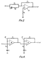
- Figure 2 is a circuit diagram of a preferred anti-buffet (ABF)filter;
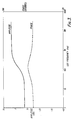
- Figure 3 is a graph of the ABF characteristics;
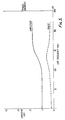
- Figure 4 is a circuit diagram of a preferred anti-enhancement filter (AEF), and Figure 5 is a graph of the filter characteristics;
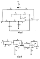
- Figure 6 is a circuit diagram of a low pass filter for defining an upper limit of the feedback loop bandwidth;
- Figure 7 is a graph of the low pass filter characteristics;
- Figure 8 is a circuit diagram of an ABEF combining both AEF and ABF characteristics;
- Figure 9 is a graph of the transfer functions of the ABEF of figure 8.
- Referring to Figure 1 of the Drawings, the active noise reduction system illustrated comprises a generally cup-shaped
circumaural earphone structure 1 arranged to enclose the wearer's ear 2. The rim of thestructure 1 is cushioned against the side of the wearer'shead 3 by means of acompliant ring cushion 4. Theearphone structure 1 embodies a small noise pick-up microphone 5, which detects the noise within the earphone adjacent to the wearer's ear 2 and provides an electrical output dependent upon the detected noise. This output signal from the microphone is passed through an anti-buffet filter 6, aloop stabilisation unit 7,a low-pass filter 8, ananti-enhancement filter 10 andamplifier 12, to a noise cancelling sound generator (loudspeaker) 14 which is mounted on abaffle 16 withinstructure 1.Loop stabilisation unit 7 includes aphase inverter 72, a loop stabilizing filter 74 (which may be incorporated in low-pass filter 8 as in Figure 6) for filtering out very high frequencies, and avoltage limiting circuit 76 comprising a zener diode switching arrangement for limiting high amplitude input signals. Filter 6 is placed first in the feedback loop in order to minimise signal values in the loop. The effect of the anti-enhancement filter is to reduce noise effects arising from imperfect transfer functions of microphone 5 andgenerator 14. - A speech signal is injected between
anti-enhancement filter 10 andamplifier 12 at aninput node 18. The introduction of the speech signal at this point allows the speech signal to be substantially uncoloured by the loop filters. If desired the speech signals may be pre-emphasised by amplification where they may be attenuated by the ANR system. - Referring to Figure 2, the ABF 6 comprises an
amplifier 20 having a negative feedback loop with a resistor R1 connected to its inverting input, which receives an input signal from a resistive/capacitive network R2, R3, C1. The non-inverting input of the amplifier is connected through a resistor R4 to ground. - The characteristics of ABF 6 are shown in Figure 3, whence it may be seen that the filter has a loss factor of about 8db up to about 100 Hz at which frequency the loss reduces continuously until at about 500Hz the filter exhibits a small gain factor.
- The phase shift introduced by the filter is an advance with increasing frequency rising in the transitional region from the base level of substantially 180° (the filter includes an inverting amplifier) to a maximum at about 200 Hz of about 215°. This phase shift must be taken into account when considering the overall loop stability. The effect of the ABF 6 on the overall feedback loop transfer function is to attenuate the low frequency end of the function whereby noise in the frequency range up to 200Hz is severely attenuated.
- The preferred form of AEF is shown in Figure 4 as comprising two
cascaded stages 21, 22, each stage comprising anamplifier 24 with a resistor R1 in a negative feedback loop and with the inverting amplifier input being connected to ground via the series combination of a resistor R2 and capacitor C1. The filter characteristics are shown in Figure 5 with the gain having step-form, being roughly 0db up to 100 Hz and then rising to 10db gain at 1 kHz. The phase shift, a phase advance with increasing frequency, rises in the region in which the gain changes, from a base level of substantially 0° a maximum value of 25° at roughly 500 Hz. - Because of the precise transfer functions of the microphone and generator, the gain reduces to a minimum value at about 500 Hz whereas the phase shift in this area rises to a maximum of about more than 3π/2. By providing AEF, the transfer functions are modified in this area to reduce phase shift and increase gain, thereby reducing signal enhancement.
- A circuit diagram of low pass filter 8 is shown in Figure 6 as comprising a transitional second order filter including an
amplifier 60 having a non-inverting input connected to a filter input via resistors R1, R2 and a capacitor C1 coupled between the amplifier input and ground. Two feedback loops are provided from the amplifier output to the non-inverting input: a first loop including a capacitor C2 and a second loop comprising resistors R3, R4, R5 and a capacitor C3 in series with a resistor R9 connected between resistors R4, R5 and ground. A further feedback loop is provided comprising a resistor R7 connected between the amplifier output and the inverting amplifier input. A further resistor R8 is connected between resistor R7 and ground. - The characteristics of the filter are shown in Figure 7 where the gain is close to 0db up to about 1000Hz and is about -30db around 10,000Hz. The gain decreases between these regions relatively quickly in a cut-off region.
- The phase shift across the filter is roughly 150°, (the filter includes a non-inverting amplifier) in the region below 1,000Hz and above 10,000Hz, but decreases to a minimum, (a phase lag with increasing frequency) of about 45° in the centre of the cut-off region. Such a phase change of roughly 105° is acceptable and is much smaller than 180 degrees resulting from a conventional second order low-pass filter. Although a second order filter is shown, the filter could be a higher or lower order if desired.
- Referring now to Figure 8, there is shown a high pass filter which combines the functions of the AEF and ABF and is herein referred to as an ABEF. The filter is a second order filter comprising two filter sections connected in cascade, the filter sections being identical. (If desired a first order filter could be employed). Each filter section comprises an
input port 80 coupled to the inverting input of anamplifier 82 through a resistance R1 connected in parallel with a capacitance C1 and a resistance R2. The non-inverting input of the amplifier is connected to ground via a resistance R3, and the output of theamplifier 86 is connected in a negative feedback loop to the inverting input of the amplifier via a resistor R4. - Referring now to Figure 9, the characteristics of the filter of Figure 8 are shown where the gain is slightly greater than 0db up to about 500 Hz and then rises to about 10db at a frequency of 2 kHz in a transitional region between 500Hz-2kHz. The phase shift changes from a constant level of about 0° to a maximum value of substantially 60° at about 1 kHz.
- It will be appreciated that although the particular embodiment specifically described is applied to a circumaural earphone structure, the invention may also be applied to other earphone structures such as the supra-aural type.
- It will also be appreciated that the filters shown may be replaced by digital filters, and the elements of the feedback loop may be digitised by employing a micro-computer with appropriate routines. The invention claimed is intended to cover both analog and digital systems.
Claims (9)
- An active noise reduction system comprising a noise-cancelling sound generator (14), a microphone (5) acoustically coupled to said generator (14), a feedback loop connected between said microphone (5) and said generator (14), and including loop stabilisation means (7) for inverting the phase of microphone signals and filtering the microphone signals, means (12) for amplifying the phase inverted and filtered signals, and a first high pass frequency filter means (6) for filtering out sound energy from high pressure sound pulses arising from low frequency buffets, characterised in that the first filter means (6) has a gain characteristic which is relatively low in a first frequency band and then rises continuously to a relatively high value in a second frequency band, said first filter means (6) introducing a phase shift which rises to a maximum value in a transitional region of said gain characteristic of said first high pass frequency filter means, said system further comprising a second high pass filter means (10) coupled between the loop stabilising means (7) and the amplifying means (12) for increasing loop gain and/or adjusting phase shift by predetermined amounts within one or more predetermined frequency bands, wherein the second filter means (10) has a gain characteristic which is relatively low in a first frequency band and then rises continuously to a relatively high value in a second frequency band, the phase shift introduced by the second filter means (10) rises to a maximum value in the transitional region of filter gain characteristic.
- A system as claimed in claim 1, wherein the second filter means (10) includes one or more stages, each stage comprising an amplifier (24) with a negative resistive feedback loop (20, 22), and a resistive capacitive path (R2, C1) to a reference potential connected to the inverting amplifier input.
- A system as claimed in claim 1 or claim 2, wherein the functions of the first (6) and second (10) filters are provided by a single high pass filter means, with the transfer characteristics selected to filter out sound energy from high pressure sound pulses and to increase loop gain and/or adjust phase shift to compensate for transfer characteristics of the microphone (5) and generator (10).
- A system as claimed in any preceding claim, and further comprising means for injecting a speech signal into the feedback loop between the filter means (10) and the amplifying means (12).
- A system as claimed in any preceding claim, wherein the second high pass filter means (10) includes one or more stages, each stage including a first order high pass active filter, the active filter network being coupled to the operational amplifier for providing a high pass characteristic.
- A system as claimed in claim 5, wherein the first filter means (6) comprises one or more stages, each stage comprising a first order high pass active filter.
- A system as claimed in claim 6, wherein the first high pass frequency filter means (6) comprises a resistive-capacitive combination (R2, R3, C1) and an amplifier (20) having inverting and non-inverting inputs with a negative feedback loop (R1), an input of the filter means being provided on one side of said resistive-capacitive combination (R2, R3, C1) and the other side of said combination being connected to said inverting input and the non-inverting input being connected to reference potential via a resistive connection (R4).
- A system as claimed in any preceding claim, wherein said loop stabilisation means (7) includes means (76) for limiting the amplitude of the signals in the feedback loop.
- A system as claimed in any preceding claim, wherein the first high pass frequency filter means (6) is connected between the microphone (5) and said loop stabilisation means (7).
Priority Applications (1)
| Application Number | Priority Date | Filing Date | Title |
|---|---|---|---|
| AT88905991T ATE82083T1 (en) | 1987-07-20 | 1988-07-20 | ARRANGEMENTS FOR NOISE REDUCTION. |
Applications Claiming Priority (6)
| Application Number | Priority Date | Filing Date | Title |
|---|---|---|---|
| GB878717042A GB8717042D0 (en) | 1987-07-20 | 1987-07-20 | Noise reduction systems |
| GB878717043A GB8717043D0 (en) | 1987-07-20 | 1987-07-20 | Noise reduction systems |
| GB8717042 | 1987-07-20 | ||
| GB878717040A GB8717040D0 (en) | 1987-07-20 | 1987-07-20 | Noise reduction systems |
| GB8717043 | 1987-07-20 | ||
| GB8717040 | 1987-07-20 |
Publications (2)
| Publication Number | Publication Date |
|---|---|
| EP0327617A1 EP0327617A1 (en) | 1989-08-16 |
| EP0327617B1 true EP0327617B1 (en) | 1992-11-04 |
Family
ID=27263515
Family Applications (1)
| Application Number | Title | Priority Date | Filing Date |
|---|---|---|---|
| EP88905991A Expired - Lifetime EP0327617B1 (en) | 1987-07-20 | 1988-07-20 | Improvements relating to noise reduction systems |
Country Status (6)
| Country | Link |
|---|---|
| EP (1) | EP0327617B1 (en) |
| AT (1) | ATE82083T1 (en) |
| AU (1) | AU608041B2 (en) |
| CA (1) | CA1299725C (en) |
| DE (1) | DE3875717T2 (en) |
| WO (1) | WO1989000746A1 (en) |
Families Citing this family (16)
| Publication number | Priority date | Publication date | Assignee | Title |
|---|---|---|---|---|
| US5091954A (en) * | 1989-03-01 | 1992-02-25 | Sony Corporation | Noise reducing receiver device |
| US5276740A (en) * | 1990-01-19 | 1994-01-04 | Sony Corporation | Earphone device |
| WO1991011078A1 (en) * | 1990-01-19 | 1991-07-25 | Sony Corporation | Earphone device |
| US5224168A (en) * | 1991-05-08 | 1993-06-29 | Sri International | Method and apparatus for the active reduction of compression waves |
| WO1994017513A1 (en) * | 1993-01-29 | 1994-08-04 | Active Noise And Vibration Technologies, Inc. | Earpiece for active noise cancelling headset |
| EP0967592B1 (en) * | 1993-06-23 | 2007-01-24 | Noise Cancellation Technologies, Inc. | Variable gain active noise cancellation system with improved residual noise sensing |
| AT403417B (en) * | 1995-04-25 | 1998-02-25 | Fritz Dr Paschke | SOUND FILTER DEVICE |
| US5675658A (en) * | 1995-07-27 | 1997-10-07 | Brittain; Thomas Paige | Active noise reduction headset |
| US20010036283A1 (en) * | 2000-03-07 | 2001-11-01 | Mark Donaldson | Active noise reduction system |
| US8077874B2 (en) | 2006-04-24 | 2011-12-13 | Bose Corporation | Active noise reduction microphone placing |
| US8054992B2 (en) * | 2006-04-24 | 2011-11-08 | Bose Corporation | High frequency compensating |
| DE102009005302B4 (en) | 2009-01-16 | 2022-01-05 | Sennheiser Electronic Gmbh & Co. Kg | Protective helmet and device for active noise suppression |
| US8085946B2 (en) | 2009-04-28 | 2011-12-27 | Bose Corporation | ANR analysis side-chain data support |
| US8345888B2 (en) | 2009-04-28 | 2013-01-01 | Bose Corporation | Digital high frequency phase compensation |
| US8553900B2 (en) * | 2010-05-14 | 2013-10-08 | Creative Technology Ltd | Noise reduction circuit with monitoring functionality |
| US11164554B2 (en) | 2020-03-06 | 2021-11-02 | Bose Corporation | Wearable active noise reduction (ANR) device having low frequency feedback loop modulation |
Family Cites Families (6)
| Publication number | Priority date | Publication date | Assignee | Title |
|---|---|---|---|---|
| US4061875A (en) * | 1977-02-22 | 1977-12-06 | Stephen Freifeld | Audio processor for use in high noise environments |
| GB2104754B (en) * | 1981-06-12 | 1985-04-24 | George Brian Barrie Chaplin | Method and apparatus for reducing repetitive noise entering the ear |
| ZA825676B (en) * | 1981-08-11 | 1983-06-29 | Sound Attenuators Ltd | Method and apparatus for low frequency active attennuation |
| DE3133107A1 (en) * | 1981-08-21 | 1983-03-10 | Michael 5440 Mayen Hofmann | Personal sound protection |
| GB2172769B (en) * | 1985-03-21 | 1988-07-06 | Topexpress Ltd | Improvements in acoustic attenuation |
| GB8517716D0 (en) * | 1985-07-13 | 1985-08-21 | Plessey Co Plc | Noise reduction arrangements |
-
1988
- 1988-07-19 CA CA000572420A patent/CA1299725C/en not_active Expired - Lifetime
- 1988-07-20 DE DE8888905991T patent/DE3875717T2/en not_active Expired - Fee Related
- 1988-07-20 EP EP88905991A patent/EP0327617B1/en not_active Expired - Lifetime
- 1988-07-20 WO PCT/GB1988/000581 patent/WO1989000746A1/en not_active Ceased
- 1988-07-20 AU AU20716/88A patent/AU608041B2/en not_active Ceased
- 1988-07-20 AT AT88905991T patent/ATE82083T1/en not_active IP Right Cessation
Also Published As
| Publication number | Publication date |
|---|---|
| AU2071688A (en) | 1989-02-13 |
| DE3875717T2 (en) | 1993-03-18 |
| WO1989000746A1 (en) | 1989-01-26 |
| CA1299725C (en) | 1992-04-28 |
| AU608041B2 (en) | 1991-03-21 |
| DE3875717D1 (en) | 1992-12-10 |
| ATE82083T1 (en) | 1992-11-15 |
| EP0327617A1 (en) | 1989-08-16 |
Similar Documents
| Publication | Publication Date | Title |
|---|---|---|
| US4953217A (en) | Noise reduction system | |
| CA1299725C (en) | Noise reduction systems | |
| US5182774A (en) | Noise cancellation headset | |
| US5452361A (en) | Reduced VLF overload susceptibility active noise cancellation headset | |
| JP2989843B2 (en) | Active noise reduction system | |
| US8948409B2 (en) | Audio headset with active noise control of the non-adaptive type for listening to an audio music source and/or for “hands-free” telephony functions | |
| GB2455821A (en) | Active noise cancellation system with split digital filter | |
| US20120014532A1 (en) | Noise-canceling headphone | |
| GB2455828A (en) | Noise cancellation system with adaptive filter and two different sample rates | |
| JPH06503897A (en) | Noise cancellation system | |
| AU3400989A (en) | Active acoustic attenuation system with differential filtering | |
| US6069959A (en) | Active headset | |
| EP0705472A1 (en) | Variable gain active noise cancellation system with improved residual noise sensing | |
| CA2170026C (en) | Digitally controlled analog cancellation system | |
| JPH03157098A (en) | Hearing aid equipped with compensation of acoustic feedback | |
| CN114787911A (en) | Noise elimination system and signal processing method of ear-wearing type playing device | |
| EP0212840B1 (en) | Noise reduction device | |
| EP0195641A2 (en) | Improvements relating to noise reduction arrangements | |
| GB2172470A (en) | Improvements relating to noise reduction arrangements | |
| GB2234881A (en) | Noise reduction system | |
| US20170127171A1 (en) | Noise reduction system | |
| US20050135646A1 (en) | Feedback compensation device and method, and hearing aid device employing same | |
| US20050226439A1 (en) | Noise cancellation using virtually lossless sensing method | |
| EP0192379B1 (en) | Improvements relating to noise reduction arrangements | |
| US5191616A (en) | Acoustic apparatus |
Legal Events
| Date | Code | Title | Description |
|---|---|---|---|
| PUAI | Public reference made under article 153(3) epc to a published international application that has entered the european phase |
Free format text: ORIGINAL CODE: 0009012 |
|
| 17P | Request for examination filed |
Effective date: 19890307 |
|
| AK | Designated contracting states |
Kind code of ref document: A1 Designated state(s): AT BE CH DE FR GB IT LI LU NL SE |
|
| RAP1 | Party data changed (applicant data changed or rights of an application transferred) |
Owner name: SIEMENS PLESSEY ELECTRONIC SYSTEMS LIMITED |
|
| 17Q | First examination report despatched |
Effective date: 19910528 |
|
| GRAA | (expected) grant |
Free format text: ORIGINAL CODE: 0009210 |
|
| AK | Designated contracting states |
Kind code of ref document: B1 Designated state(s): AT BE CH DE FR GB IT LI LU NL SE |
|
| REF | Corresponds to: |
Ref document number: 82083 Country of ref document: AT Date of ref document: 19921115 Kind code of ref document: T |
|
| ET | Fr: translation filed | ||
| ITF | It: translation for a ep patent filed | ||
| REF | Corresponds to: |
Ref document number: 3875717 Country of ref document: DE Date of ref document: 19921210 |
|
| PLBE | No opposition filed within time limit |
Free format text: ORIGINAL CODE: 0009261 |
|
| STAA | Information on the status of an ep patent application or granted ep patent |
Free format text: STATUS: NO OPPOSITION FILED WITHIN TIME LIMIT |
|
| 26N | No opposition filed | ||
| EPTA | Lu: last paid annual fee | ||
| EAL | Se: european patent in force in sweden |
Ref document number: 88905991.1 |
|
| REG | Reference to a national code |
Ref country code: FR Ref legal event code: CD |
|
| REG | Reference to a national code |
Ref country code: GB Ref legal event code: IF02 |
|
| REG | Reference to a national code |
Ref country code: CH Ref legal event code: PFA Owner name: BAE SYSTEMS (DEFENCE SYSTEMS) LIMITED Free format text: SIEMENS PLESSEY ELECTRONIC SYSTEMS LIMITED#OAKCROFT ROAD#CHESSINGTON/SURREY (GB) -TRANSFER TO- BAE SYSTEMS (DEFENCE SYSTEMS) LIMITED#WARWICK HOUSE P O BOX 87 FARNBOROUGH AEROPSPACE CENTRE#FARNBOROUGH HAMPSHIRE GU14 6YU (GB) |
|
| NLT1 | Nl: modifications of names registered in virtue of documents presented to the patent office pursuant to art. 16 a, paragraph 1 |
Owner name: BAE SYSTEMS (DEFENCE SYSTEMS) LIMITED Owner name: BRITISH AEROSPACE DEFENCE SYSTEMS LIMITED |
|
| REG | Reference to a national code |
Ref country code: FR Ref legal event code: CD |
|
| PGFP | Annual fee paid to national office [announced via postgrant information from national office to epo] |
Ref country code: AT Payment date: 20040608 Year of fee payment: 17 |
|
| PGFP | Annual fee paid to national office [announced via postgrant information from national office to epo] |
Ref country code: FR Payment date: 20040610 Year of fee payment: 17 |
|
| PGFP | Annual fee paid to national office [announced via postgrant information from national office to epo] |
Ref country code: CH Payment date: 20040611 Year of fee payment: 17 |
|
| PGFP | Annual fee paid to national office [announced via postgrant information from national office to epo] |
Ref country code: NL Payment date: 20040614 Year of fee payment: 17 Ref country code: GB Payment date: 20040614 Year of fee payment: 17 |
|
| PGFP | Annual fee paid to national office [announced via postgrant information from national office to epo] |
Ref country code: SE Payment date: 20040616 Year of fee payment: 17 Ref country code: LU Payment date: 20040616 Year of fee payment: 17 |
|
| PGFP | Annual fee paid to national office [announced via postgrant information from national office to epo] |
Ref country code: DE Payment date: 20040621 Year of fee payment: 17 |
|
| PGFP | Annual fee paid to national office [announced via postgrant information from national office to epo] |
Ref country code: BE Payment date: 20040713 Year of fee payment: 17 |
|
| PG25 | Lapsed in a contracting state [announced via postgrant information from national office to epo] |
Ref country code: LU Free format text: LAPSE BECAUSE OF NON-PAYMENT OF DUE FEES Effective date: 20050720 Ref country code: IT Free format text: LAPSE BECAUSE OF NON-PAYMENT OF DUE FEES;WARNING: LAPSES OF ITALIAN PATENTS WITH EFFECTIVE DATE BEFORE 2007 MAY HAVE OCCURRED AT ANY TIME BEFORE 2007. THE CORRECT EFFECTIVE DATE MAY BE DIFFERENT FROM THE ONE RECORDED. Effective date: 20050720 Ref country code: GB Free format text: LAPSE BECAUSE OF NON-PAYMENT OF DUE FEES Effective date: 20050720 Ref country code: AT Free format text: LAPSE BECAUSE OF NON-PAYMENT OF DUE FEES Effective date: 20050720 |
|
| PG25 | Lapsed in a contracting state [announced via postgrant information from national office to epo] |
Ref country code: SE Free format text: LAPSE BECAUSE OF NON-PAYMENT OF DUE FEES Effective date: 20050721 |
|
| PG25 | Lapsed in a contracting state [announced via postgrant information from national office to epo] |
Ref country code: LI Free format text: LAPSE BECAUSE OF NON-PAYMENT OF DUE FEES Effective date: 20050731 Ref country code: CH Free format text: LAPSE BECAUSE OF NON-PAYMENT OF DUE FEES Effective date: 20050731 Ref country code: BE Free format text: LAPSE BECAUSE OF NON-PAYMENT OF DUE FEES Effective date: 20050731 |
|
| PG25 | Lapsed in a contracting state [announced via postgrant information from national office to epo] |
Ref country code: NL Free format text: LAPSE BECAUSE OF NON-PAYMENT OF DUE FEES Effective date: 20060201 Ref country code: DE Free format text: LAPSE BECAUSE OF NON-PAYMENT OF DUE FEES Effective date: 20060201 |
|
| REG | Reference to a national code |
Ref country code: CH Ref legal event code: PL |
|
| EUG | Se: european patent has lapsed | ||
| GBPC | Gb: european patent ceased through non-payment of renewal fee |
Effective date: 20050720 |
|
| PG25 | Lapsed in a contracting state [announced via postgrant information from national office to epo] |
Ref country code: FR Free format text: LAPSE BECAUSE OF NON-PAYMENT OF DUE FEES Effective date: 20060331 |
|
| NLV4 | Nl: lapsed or anulled due to non-payment of the annual fee |
Effective date: 20060201 |
|
| REG | Reference to a national code |
Ref country code: FR Ref legal event code: ST Effective date: 20060331 |
|
| BERE | Be: lapsed |
Owner name: *BAE SYSTEMS DEFENCE SYSTEMS LTD Effective date: 20050731 |