EP0327586B1 - Food container and method of manufacturing - Google Patents
Food container and method of manufacturing Download PDFInfo
- Publication number
- EP0327586B1 EP0327586B1 EP87907488A EP87907488A EP0327586B1 EP 0327586 B1 EP0327586 B1 EP 0327586B1 EP 87907488 A EP87907488 A EP 87907488A EP 87907488 A EP87907488 A EP 87907488A EP 0327586 B1 EP0327586 B1 EP 0327586B1
- Authority
- EP
- European Patent Office
- Prior art keywords
- shield
- inches
- food
- further characterized
- container
- Prior art date
- Legal status (The legal status is an assumption and is not a legal conclusion. Google has not performed a legal analysis and makes no representation as to the accuracy of the status listed.)
- Expired - Lifetime
Links
- 235000013305 food Nutrition 0.000 title claims abstract description 180
- 238000004519 manufacturing process Methods 0.000 title claims description 4
- 230000005855 radiation Effects 0.000 claims abstract description 63
- 239000000126 substance Substances 0.000 claims abstract description 57
- 230000000694 effects Effects 0.000 claims abstract description 36
- 239000003989 dielectric material Substances 0.000 claims abstract description 19
- 239000000463 material Substances 0.000 claims description 105
- 238000010438 heat treatment Methods 0.000 claims description 65
- 238000000034 method Methods 0.000 claims description 42
- 230000005684 electric field Effects 0.000 claims description 9
- 238000012360 testing method Methods 0.000 claims description 7
- 230000004044 response Effects 0.000 claims description 3
- 230000001678 irradiating effect Effects 0.000 claims 1
- 230000013011 mating Effects 0.000 claims 1
- 238000007789 sealing Methods 0.000 claims 1
- 229910052751 metal Inorganic materials 0.000 abstract description 32
- 239000002184 metal Substances 0.000 abstract description 32
- 241001047198 Scomberomorus semifasciatus Species 0.000 description 49
- 235000012467 brownies Nutrition 0.000 description 49
- 239000011888 foil Substances 0.000 description 39
- 235000015243 ice cream Nutrition 0.000 description 31
- 229910052782 aluminium Inorganic materials 0.000 description 26
- XAGFODPZIPBFFR-UHFFFAOYSA-N aluminium Chemical compound [Al] XAGFODPZIPBFFR-UHFFFAOYSA-N 0.000 description 26
- 235000015067 sauces Nutrition 0.000 description 23
- 238000013021 overheating Methods 0.000 description 10
- 238000012937 correction Methods 0.000 description 9
- 238000002474 experimental method Methods 0.000 description 9
- 239000003990 capacitor Substances 0.000 description 7
- 229920002301 cellulose acetate Polymers 0.000 description 7
- 238000002844 melting Methods 0.000 description 7
- 230000008018 melting Effects 0.000 description 7
- 238000013459 approach Methods 0.000 description 6
- 230000008901 benefit Effects 0.000 description 5
- 239000000123 paper Substances 0.000 description 5
- 239000011248 coating agent Substances 0.000 description 4
- 238000000576 coating method Methods 0.000 description 4
- 230000015556 catabolic process Effects 0.000 description 3
- 238000010521 absorption reaction Methods 0.000 description 2
- 230000002411 adverse Effects 0.000 description 2
- 239000004020 conductor Substances 0.000 description 2
- 238000010276 construction Methods 0.000 description 2
- 238000013461 design Methods 0.000 description 2
- 230000002349 favourable effect Effects 0.000 description 2
- 238000012986 modification Methods 0.000 description 2
- 230000004048 modification Effects 0.000 description 2
- 239000005022 packaging material Substances 0.000 description 2
- 238000004806 packaging method and process Methods 0.000 description 2
- 239000004033 plastic Substances 0.000 description 2
- 239000007787 solid Substances 0.000 description 2
- QTBSBXVTEAMEQO-UHFFFAOYSA-M Acetate Chemical compound CC([O-])=O QTBSBXVTEAMEQO-UHFFFAOYSA-M 0.000 description 1
- 229920002799 BoPET Polymers 0.000 description 1
- 235000011299 Brassica oleracea var botrytis Nutrition 0.000 description 1
- 235000017647 Brassica oleracea var italica Nutrition 0.000 description 1
- 244000308180 Brassica oleracea var. italica Species 0.000 description 1
- 244000307700 Fragaria vesca Species 0.000 description 1
- 235000016623 Fragaria vesca Nutrition 0.000 description 1
- 235000011363 Fragaria x ananassa Nutrition 0.000 description 1
- 239000005041 Mylar™ Substances 0.000 description 1
- 239000004809 Teflon Substances 0.000 description 1
- 229920006362 Teflon® Polymers 0.000 description 1
- 230000009471 action Effects 0.000 description 1
- 235000015173 baked goods and baking mixes Nutrition 0.000 description 1
- 230000008859 change Effects 0.000 description 1
- 235000013351 cheese Nutrition 0.000 description 1
- 238000006243 chemical reaction Methods 0.000 description 1
- 150000001875 compounds Chemical class 0.000 description 1
- 239000012141 concentrate Substances 0.000 description 1
- 238000010411 cooking Methods 0.000 description 1
- 238000013016 damping Methods 0.000 description 1
- 230000001627 detrimental effect Effects 0.000 description 1
- 238000010586 diagram Methods 0.000 description 1
- 238000009713 electroplating Methods 0.000 description 1
- 230000002708 enhancing effect Effects 0.000 description 1
- -1 for example Substances 0.000 description 1
- 235000013611 frozen food Nutrition 0.000 description 1
- 230000009931 harmful effect Effects 0.000 description 1
- 230000001939 inductive effect Effects 0.000 description 1
- 238000002372 labelling Methods 0.000 description 1
- 238000005259 measurement Methods 0.000 description 1
- 238000005457 optimization Methods 0.000 description 1
- 238000012856 packing Methods 0.000 description 1
- 230000003071 parasitic effect Effects 0.000 description 1
- 230000008569 process Effects 0.000 description 1
- 238000012545 processing Methods 0.000 description 1
- 230000009467 reduction Effects 0.000 description 1
- 230000001105 regulatory effect Effects 0.000 description 1
- 238000000926 separation method Methods 0.000 description 1
- 238000004544 sputter deposition Methods 0.000 description 1
- 239000012780 transparent material Substances 0.000 description 1
- XLYOFNOQVPJJNP-UHFFFAOYSA-N water Substances O XLYOFNOQVPJJNP-UHFFFAOYSA-N 0.000 description 1
- 239000008256 whipped cream Substances 0.000 description 1
Images





Classifications
-
- H—ELECTRICITY
- H05—ELECTRIC TECHNIQUES NOT OTHERWISE PROVIDED FOR
- H05B—ELECTRIC HEATING; ELECTRIC LIGHT SOURCES NOT OTHERWISE PROVIDED FOR; CIRCUIT ARRANGEMENTS FOR ELECTRIC LIGHT SOURCES, IN GENERAL
- H05B6/00—Heating by electric, magnetic or electromagnetic fields
- H05B6/64—Heating using microwaves
-
- B—PERFORMING OPERATIONS; TRANSPORTING
- B65—CONVEYING; PACKING; STORING; HANDLING THIN OR FILAMENTARY MATERIAL
- B65D—CONTAINERS FOR STORAGE OR TRANSPORT OF ARTICLES OR MATERIALS, e.g. BAGS, BARRELS, BOTTLES, BOXES, CANS, CARTONS, CRATES, DRUMS, JARS, TANKS, HOPPERS, FORWARDING CONTAINERS; ACCESSORIES, CLOSURES, OR FITTINGS THEREFOR; PACKAGING ELEMENTS; PACKAGES
- B65D81/00—Containers, packaging elements, or packages, for contents presenting particular transport or storage problems, or adapted to be used for non-packaging purposes after removal of contents
- B65D81/34—Containers, packaging elements, or packages, for contents presenting particular transport or storage problems, or adapted to be used for non-packaging purposes after removal of contents for packaging foodstuffs or other articles intended to be cooked or heated within the package
- B65D81/3446—Containers, packaging elements, or packages, for contents presenting particular transport or storage problems, or adapted to be used for non-packaging purposes after removal of contents for packaging foodstuffs or other articles intended to be cooked or heated within the package specially adapted to be heated by microwaves
- B65D81/3453—Rigid containers, e.g. trays, bottles, boxes, cups
-
- B—PERFORMING OPERATIONS; TRANSPORTING
- B65—CONVEYING; PACKING; STORING; HANDLING THIN OR FILAMENTARY MATERIAL
- B65D—CONTAINERS FOR STORAGE OR TRANSPORT OF ARTICLES OR MATERIALS, e.g. BAGS, BARRELS, BOTTLES, BOXES, CANS, CARTONS, CRATES, DRUMS, JARS, TANKS, HOPPERS, FORWARDING CONTAINERS; ACCESSORIES, CLOSURES, OR FITTINGS THEREFOR; PACKAGING ELEMENTS; PACKAGES
- B65D2581/00—Containers, packaging elements, or packages, for contents presenting particular transport or storage problems, or adapted to be used for non-packaging purposes after removal of contents
- B65D2581/34—Containers, packaging elements, or packages, for contents presenting particular transport or storage problems, or adapted to be used for non-packaging purposes after removal of contents for packaging foodstuffs or other articles intended to be cooked or heated within
- B65D2581/3401—Cooking or heating method specially adapted to the contents of the package
- B65D2581/3429—Packages containing a secondary product to be cooked and discharged over the primary product
- B65D2581/3431—Packages containing a secondary product to be cooked and discharged over the primary product the secondary product, e.g. fudge, being heated over ice-cream
-
- B—PERFORMING OPERATIONS; TRANSPORTING
- B65—CONVEYING; PACKING; STORING; HANDLING THIN OR FILAMENTARY MATERIAL
- B65D—CONTAINERS FOR STORAGE OR TRANSPORT OF ARTICLES OR MATERIALS, e.g. BAGS, BARRELS, BOTTLES, BOXES, CANS, CARTONS, CRATES, DRUMS, JARS, TANKS, HOPPERS, FORWARDING CONTAINERS; ACCESSORIES, CLOSURES, OR FITTINGS THEREFOR; PACKAGING ELEMENTS; PACKAGES
- B65D2581/00—Containers, packaging elements, or packages, for contents presenting particular transport or storage problems, or adapted to be used for non-packaging purposes after removal of contents
- B65D2581/34—Containers, packaging elements, or packages, for contents presenting particular transport or storage problems, or adapted to be used for non-packaging purposes after removal of contents for packaging foodstuffs or other articles intended to be cooked or heated within
- B65D2581/3437—Containers, packaging elements, or packages, for contents presenting particular transport or storage problems, or adapted to be used for non-packaging purposes after removal of contents for packaging foodstuffs or other articles intended to be cooked or heated within specially adapted to be heated by microwaves
- B65D2581/3439—Means for affecting the heating or cooking properties
- B65D2581/344—Geometry or shape factors influencing the microwave heating properties
- B65D2581/3441—3-D geometry or shape factors, e.g. depth-wise
-
- B—PERFORMING OPERATIONS; TRANSPORTING
- B65—CONVEYING; PACKING; STORING; HANDLING THIN OR FILAMENTARY MATERIAL
- B65D—CONTAINERS FOR STORAGE OR TRANSPORT OF ARTICLES OR MATERIALS, e.g. BAGS, BARRELS, BOTTLES, BOXES, CANS, CARTONS, CRATES, DRUMS, JARS, TANKS, HOPPERS, FORWARDING CONTAINERS; ACCESSORIES, CLOSURES, OR FITTINGS THEREFOR; PACKAGING ELEMENTS; PACKAGES
- B65D2581/00—Containers, packaging elements, or packages, for contents presenting particular transport or storage problems, or adapted to be used for non-packaging purposes after removal of contents
- B65D2581/34—Containers, packaging elements, or packages, for contents presenting particular transport or storage problems, or adapted to be used for non-packaging purposes after removal of contents for packaging foodstuffs or other articles intended to be cooked or heated within
- B65D2581/3437—Containers, packaging elements, or packages, for contents presenting particular transport or storage problems, or adapted to be used for non-packaging purposes after removal of contents for packaging foodstuffs or other articles intended to be cooked or heated within specially adapted to be heated by microwaves
- B65D2581/3471—Microwave reactive substances present in the packaging material
- B65D2581/3472—Aluminium or compounds thereof
-
- B—PERFORMING OPERATIONS; TRANSPORTING
- B65—CONVEYING; PACKING; STORING; HANDLING THIN OR FILAMENTARY MATERIAL
- B65D—CONTAINERS FOR STORAGE OR TRANSPORT OF ARTICLES OR MATERIALS, e.g. BAGS, BARRELS, BOTTLES, BOXES, CANS, CARTONS, CRATES, DRUMS, JARS, TANKS, HOPPERS, FORWARDING CONTAINERS; ACCESSORIES, CLOSURES, OR FITTINGS THEREFOR; PACKAGING ELEMENTS; PACKAGES
- B65D2581/00—Containers, packaging elements, or packages, for contents presenting particular transport or storage problems, or adapted to be used for non-packaging purposes after removal of contents
- B65D2581/34—Containers, packaging elements, or packages, for contents presenting particular transport or storage problems, or adapted to be used for non-packaging purposes after removal of contents for packaging foodstuffs or other articles intended to be cooked or heated within
- B65D2581/3437—Containers, packaging elements, or packages, for contents presenting particular transport or storage problems, or adapted to be used for non-packaging purposes after removal of contents for packaging foodstuffs or other articles intended to be cooked or heated within specially adapted to be heated by microwaves
- B65D2581/3486—Dielectric characteristics of microwave reactive packaging
- B65D2581/3489—Microwave reflector, i.e. microwave shield
-
- Y—GENERAL TAGGING OF NEW TECHNOLOGICAL DEVELOPMENTS; GENERAL TAGGING OF CROSS-SECTIONAL TECHNOLOGIES SPANNING OVER SEVERAL SECTIONS OF THE IPC; TECHNICAL SUBJECTS COVERED BY FORMER USPC CROSS-REFERENCE ART COLLECTIONS [XRACs] AND DIGESTS
- Y10—TECHNICAL SUBJECTS COVERED BY FORMER USPC
- Y10S—TECHNICAL SUBJECTS COVERED BY FORMER USPC CROSS-REFERENCE ART COLLECTIONS [XRACs] AND DIGESTS
- Y10S99/00—Foods and beverages: apparatus
- Y10S99/14—Induction heating
Definitions
- the present invention is directed to a food container and a method of making the food container.
- the food container is intended for use in a microwave oven.
- the present invention relates to a package for heating a plurality of food materials in a microwave environment.
- the present invention is intended for instances where two or more different food materials are to be simultaneously heated in a microwave oven, but one food material requires more heat than another.
- the process of heating one food material more than another is referred to as "differential heating.” Differential heating could be accomplished by employing a conductive shield, if certain problems could somehow be avoided.
- sparks and popping noises would occur when the microwave oven was turned on. This is commonly called “arcing”, and has been a problem for many years--usually circumvented by avoiding use of metal in a microwave food package. Severe arcing could cause the package to burn.
- Some other problems associated with the use of a metal or conductive shield include, in addition to arcing, scorching of the product or package, melting the package, resonant retransmission, retransmission on the edges of the shield, burning the package, localized overheating, standing waves, and apparent leakage of microwaves into the package. Applicant discovered that these problems all appear to be associated with resonances in the conductive shield.
- the present invention substantially eliminates arcing and other problems associated with resonance in a food container for a microwave environment, where the food container employs metal components or a conductive shield.
- the problem of arcing has plagued the art for many years where attempts have been made to use metallic shields to accomplish differential heating of food substances by microwave energy.
- the present invention relates to the discovery that arcing can be substantially eliminated by selecting an appropriate geometry for the metallic components of the food package. This discovery allows metal shields to be conveniently used to accomplish differential heating of food material without arcing and without damaging the microwave oven.
- U.S. Patent No. 3,854,021 issued to Moore et al., discloses a metal shield which lowers over part of a tray when the tray is inserted into the microwave oven. Moore et al. recognize that the shield distorts the microwave field in the oven and that arcing can result if the shield has sharp edges or is near the conductive wall of the oven. Moore et al. propose the use of Teflon tape on the lower edge of the shield to prevent arcing. The Moore et al. system for shielding is impractical for existing conventional microwave ovens because it would require substantial modification of an existing oven.
- Mattisson et al. discloses that a traditional metallic tray is opaque to microwave radiation and is not suitable for use in microwave ovens which have no protection for the magnetron, because arcing may occur inside the oven cavity which may damage the magnetron. Mattisson et al. disclose a tray with aluminum foil laminate around the side walls of the tray.
- the wall between the compartments is punctured by a can opener or the like to mix the food substances after the food has been heated in a microwave oven and removed from the oven.
- Slangan et al. similarly ignore the problem of arcing, and fail to teach or suggest a solution to this problem.
- metal shielding Because of the problem of resonance, and associated problems and effects including arcing and other problems enumerated above, metal shielding has found little use in commercial applications. Most microwave heating is still done in containers which are substantially transparent to microwave radiation and which contain no metal shielding.
- a practical shield may be typically formed by wrapping the metal shield around a container such that the ends of the shield overlap. Such overlapping is believed to in effect create capacitance that tends to damp voltages which would otherwise result in arcing. Overlapping tends to eliminate problems of arcing for half wavelength resonances, or odd multiples thereof. This is especially significant, because odd multiples of half wavelength resonances present the greatest potential for arcing. Overlapping therefore is an especially effective technique for eliminating arcing.
- the loop formed by wrapping the shield around the container in effect creates some inductance.
- a tuned circuit may be effectively formed from this combination of inductance and capacitance to control resonances in the metal shield.
- the shield geometry should be designed to have non-resonant dimensions. It has been discovered that under circumstances where the shield becomes resonant, i.e., where the height, length, circumference, etc. of the shield is an integer multiple of a half wavelength, resonant voltages at the edges of the shield may be a prime cause of arcing.
- the discovery of the relationship between wavelength resonance of packaging materials and arcing has permitted metal shielding to be effectively used in packaging material while eliminating arcing.
- metallic shields may now be used to allow a first food substance to be heated by microwaves while substantially reducing the exposure of a second food substance to the heating effects of the microwaves. Differential heating of two different food substances may thereby be accomplished with relative ease, without requiring substantial modifications to existing conventional microwave ovens.
- the invention resides in a method and a food package as defined in the claims.
- the invention is preferably embodied in a package that includes a container containing a first food material to be heated by microwaves and a second food material to be shielded from the microwave radiation.
- a conductive shield is preferably wrapped around a portion of the container in close proximity to the location of the second food material.
- the container preferably has a conductive top which covers an end of the container near the second food material to be shielded.
- the conductive shield is wrapped around the container so that the shield is generally cylindrical in shape when attached to the container.
- the geometry of the shield is selected so that: where " ⁇ s " is the resonant wavelength of the microwaves in the shield, “h” is the height of the shield, “C” is the circumference of the shield, and “N” and “M” are each integers, for example, 0, 1, 2, 3, 4, etc.
- the wavelength “ ⁇ s " utilized in the equations expressed herein is the actual resonant wavelength of the shield. This wavelength “ ⁇ s " will typically be different from the wavelength " ⁇ 0" of microwaves in free space.
- the actual wavelength” ⁇ s " may be empirically measured, or it could be determined mathematically if the actual speed of light in the shield material is known and factors such as end effects, etc., are taken into consideration.
- a method for producing a non-arcing shielded container for differential heating of food material with microwave radiation includes the steps of providing a container for food having a first food material to be heated by microwave radiation and a second food material to be shielded from the heating effects of microwave radiation.
- the method includes the step of selecting a conductive shield so that the shield has a height which is substantially not equal to any multiple of a half wavelength of the microwave radiation, and the shield has a circumference which is substantially not equal to any multiple of a half wavelength of the microwave radiation, thereby avoiding resonance of the shield at the frequency of the microwave radiation to minimize arcing.
- the circumference and height of the shield are selected so that, when you add the circumference and height vectorially, the resulting vector is not equal to a half wavelength multiple of the wavelength " ⁇ s " of the microwaves. This is because resonance diagonally in the shield is possible, and should be avoided.
- the method also includes providing a shield around the container in the proximity of the second food material to be shielded to reduce the heating effect of the microwave radiation by substantially shielding the second food material and permitting differential heating of the food material in the container.
- the geometry of the shield is selected so that: where " ⁇ s " is the wavelength of the microwaves, "h” is the height of the shield, “w” is the width of the shield, and "N” and “M” are each integers, for example, 0, 1, 2, 3, 4, etc.
- a rectangular container may be constructed so that: where " ⁇ s " is the wavelength of the microwaves, "h” is the height of the shield, “p” is the perimeter of the shield, and "N” and “M” are each integers, for example, 0, 1, 2, 3, 4, etc.
- the invention may also be embodied in a generally cylindrical food container having two different food materials, one to be heated by microwave radiation and the other to be at least partially shielded from microwave radiation.
- a conductive shield may be wrapped around at least a portion of the food container with overlapping ends of the shield, where the ends of the shield which overlap are separated by a dielectric material.
- the amount of the overlap is selected to damp potential arcing currents, where the relative arcing potential is defined by: where “D” is the diameter of the cylindrically shaped shield, “h” is the height of the shield, “L” is the distance that the first end of the shield overlaps the second end of the shield, “K” is the dielectric constant of the dielectric material between the first and second ends of the shield, “d” is the distance that the first and second ends of the shield are spaced apart, and “ ⁇ 0” is the wavelength of the microwave radiation.
- the relative arcing potential is minimized by selecting dimensions for the shield which reduce the value of the relative arcing potential to a level where arcing is substantially avoided.
- the embodiment of the invention using a generally cylindrical food container having a conductive shield with overlapping ends may also be provided with a shield the geometry of which is selected so that: where " ⁇ s " is the wavelength of the microwaves, "h” is the height of the shield, “D” is the diameter of the shield, and "N” and “M” are each integers, for example, 0, 1, 2, 3, 4, etc.
- the invention may also be embodied in a package for differential heating of food material in a microwave environment which includes a frustoconical container having two food materials, one to be heated by microwaves and a second one to be shielded from microwaves.
- the package also includes a conductive shield wrapped around a portion of the frustoconical container so that the shield is also frustoconical in shape.
- the shield has a mean circumference and a height such that: where " ⁇ s " is the wavelength of the microwaves, "h” is the height of the shield, "C” is the mean circumference of the shield, and "N” and “M” are each integers, for example, 0, 1, 2, 3, 4, etc.
- a frustoconical shaped shield will normally have a range of circumferences from a maximum circumference to a minimum circumference. Preferably, the above relationship should hold true for all of the circumferences within that range, and not just the mean circumference. Resonance of the shield and resonant voltages at the edges of the shield are avoided to minimize arcing when the package is exposed to microwave radiation.
- a conductive top covering the frustoconical container on the end of the container near the second food material to be shielded is also preferably provided.
- a frustoconical food container having a conductive shield with overlapping ends may be utilized.
- the geometry of the shield is selected in order to damp potential arcing currents, where the relative arcing potential is defined by: where "D” is the mean diameter of the frustoconical shaped shield, “h” is the height of the shield, “L” is the distance that the first end of the shield overlaps the second end of the shield, “K” is the dielectric constant of the dielectric material between the first and second ends of the shield, “d” is the distance that the first and second ends of the shield are spaced apart, and “ ⁇ 0" is the wavelength of the microwave radiation.
- the relative arcing potential is reduced or minimized by selecting dimensions for the shield which reduce the value of the relative arcing potential to a level where no arcing occurs.
- the relative arcing potential is minimized for all values of the range of diameters in a frustoconical shaped shield.
- a frustoconical container with an overlapping shield may also be provided where: where " ⁇ s ", “h”, “D”, “N” and “M” represent the microwave wavelength, shield height, mean diameter, and integers, respectively, as described above.
- An overlapping shield may be used with any shaped container that may be desired.
- the overlapped ends of the shield when separated electrically (typically by a dielectric material), provide capacitance that can be utilized to control arcing and other problems.
- the overlapping shield will be configured to provide some inductance also, so that the shield may be in effect "tuned” to control resonance and problems associated therewith.
- the exact configuration may need to be determined using some experimentation. If the inductance and capacitance are measurable, for example, with a network analyzer, then the amount of overlap may be varied to minimize the relative arcing potential: where "w" is the frequency of the microwaves, "l” is the inductance of the shield, and “c” is the capacitance of the shield. For example, the capacitance "c" generally increases when the amount of overlap is increased.
- the nonresonant dimensions for a shield may be determined in accordance with the teachings herein for a given microwave frequency. However, if other microwave frequencies are used, the nonresonant dimensions for an effective shield will normally change accordingly.
- wavelength " ⁇ s " of the microwave is used herein, it is defined as the actual resonant wavelength for the shield. Normally, the wavelength “ ⁇ s " for the shield will be different from the wavelength “ ⁇ 0" of the microwaves in free space. This is due to differences in the speed of light through various mediums, end effects, resistivity, stray capacitances, dielectric properties, etc.
- the actual wavelength “ ⁇ s " may be empirically determined as explained more fully hereinafter.
- the present invention provides the feature of enabling use of convenient and effective metal shielding to accomplish differential heating of various food materials in a microwave oven, while solving the problem of arcing which has plagued the art for many years.
- the present invention solves the problem of resonance, and the undesirable effects thereof.
- the problems of resonance and retransmitted fields have not even been recognized by the references cited above; and it cannot be said that prior art references obviously suggest a solution to problems they do not even recognize.
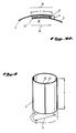
- FIGURE 1 is a cut-away side view of a preferred package including a container and three different food substances.
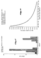
- FIGURE 2 is a perspective view of an empty container with an overlapping shield.
- FIGURE 3 is a perspective view of an overlapping conductive shield, with the container omitted, to show the geometry of the shield.
- FIGURE 3A shows a close-up cut-away top view of the overlapping portion of the shield shown in FIGURE 3.
- FIGURE 4 is a perspective view of an alternative non-overlapping conductive shield, with the container omitted, to show the geometry of the shield.
- FIGURE 5 is a graph depicting combinations of resonant geometries for a non-overlapped shield which are to be avoided.
- FIGURE 6 is a graph depicting combinations of resonant geometries for an overlapped shield which are to be avoided.
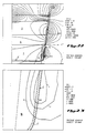
- FIGURE 7 is a graph illustrating the severity of arcing at different container heights.
- FIGURE 8 is a graph depicting the relationship between relative arcing potential and the amount of overlap of the ends of a shield.
- FIGURE 9 is a graph showing the relative heating of an overlapped shield as a function of circumference.
- FIGURE 10 is a graph illustrating field strength for a cylindrical shield as a function of the geometry of the shield.
- FIGURE 11 is a graph illustrating the field strength for a cylindrical shield as a function of the geometry of the shield.
- FIGURE 12 is a cut-away side view of an alternative embodiment using a frustoconical container, including three different food substances.
- FIGURE 13 is a side view of an empty frustoconical container with the top removed.
- FIGURE 14 is a top view of the container shown in FIGURE 13.
- FIGURE 15 is a side view of the container lid for the container illustrated in FIGURES 13 and 14.
- FIGURE 16 is a top view of the container lid illustrated in FIGURE 15.
- FIGURE 17 illustrates the dimensions for a conductive shield to be wrapped around the frustoconical container illustrated in FIGURE 13.
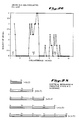
- FIGURE 18 is a computer-generated graph illustrating the electrical field around a shielded container which has various food substances present therein, and in which no gap exists between the container and the food substance at the bottom of the container.
- FIGURE 19 is a computer-generated graph illustrating a close-up view of the lower portion of the graph of FIGURE 18.
- FIGURE 20 is a computer-generated graph illustrating the electrical field around a shielded container which has a 1/16 inch gap between the container and the food substance at the bottom of the container.
- FIGURE 21 is a computer-generated graph illustrating a close-up view of the lower portion of the graph of FIGURE 20.
- FIGURE 22 is a computer-generated graph illustrating the electrical field around a shielded container where a 1/8 inch gap is provided between the container and the food substance at the bottom of the container.
- FIGURE 23 is a computer-generated graph illustrating a close-up view of the lower portion of the graph of FIGURE 22.
- FIGURE 24 is a cross-sectioned cut-away view of an alternative embodiment of a frustoconical container having air gap means at the bottom rim of the container.
- FIGURE 25 is a schematic diagram illustrating the relationship between wavelength and voltage polarities at the ends of a metal shield.
- FIGURE 26 is a graph showing the severity of arcing of a non-overlapping shielded container as a function of circumference.
- FIGURE 27 is a graph showing the relative heating of a non-overlapped shield as a function of circumference.
- FIGURE 28 is a graph showing the severity of arcing of an overlapping shielded container as a function of circumference.
- FIGURE 1 shows a cut-away view of a presently preferred package 21 including a generally cylindrical container 3 for the differential heating of food material.
- first food material 1 a second food material 2 and preferably a third food material 6.
- first food material 1 may be a brownie 1 or other baked good.
- second food material 2 may be ice cream 2 or other frozen food.
- a conductive shield 4 around the container 3.
- the container 3 should be substantially transparent to microwave radiation.
- the conductive shield 4 is preferably formed from aluminum foil 4 wrapped around the container 3. The shield 4 prevents microwaves from entering the portion of the container 3 where the second food material 2, i.e., the ice cream 2, is contained. In other words, a shielded zone 2 is created within the container 3 by the shield 4.
- Microwave radiation is allowed to enter the bottom 22 of the container 3 when the package 21 is placed in a microwave oven for heating. Microwave radiation is allowed to heat the brownie 1 which is not substantially shielded by the aluminum foil 4. In other words, the container 3 has an irradiation zone 1 which is exposed to microwave radiation.
- the package also preferably includes a top or lid 5 which fits securely over the opening in the container 3, and may be heat sealed in a manner known in the art.
- the top 5 preferably includes a conductive shielding to further shield the ice cream 2 from microwave radiation.
- the lid 5 is preferably made from foil stock with serlyn laminated to it.
- the lid 5 could be made from foil stock with paper laminated to it.
- the top 5 is preferably recessed into the container 3, as shown in FIGURE 1.
- the top 5 preferably has a conductive horizontal center 31 surrounded by a vertical wall 32 which curves into a flange 33.
- the flange 33 may mate with a lip 34 on the container 3.
- the top 5 may be sealed or fastened to the container 3 in a suitable manner known in the art.
- the top 5 may be heat sealed on the flange 33.
- a third food material 6 may be interposed between the brownie 1 and the ice cream 2.
- the third food material 6 may be a sauce 6.
- the sauce 6 may offer advantages which enhance the temperature differential between the ice cream 2 and the brownie 1.
- the sauce 6 may be chosen so that it is highly reflective of microwave energy, thereby further improving the differential heating between the brownie 1 and the ice cream 2.
- an edible reflective zone 6 may be formed inside the container 3 between the shielded zone 2 and the irradiation zone 1.
- the illustrated container or cup 3 shown in FIGURE 1 is generally cylindrical in shape, and has a height "H c " and an outside diameter "D".
- the package 21 illustrated in FIGURE 1 normally would not be suitable for use in a conventional microwave oven due to the problem of arcing, unless the geometry of the shield 4 is carefully designed in accordance with the teachings of this invention. Resonance of the shield 4 at microwave frequencies must be generally avoided in order to minimize arcing and to avoid other problems, such as melting, localized overheating, etc. Applicant has discovered that the problem of arcing can be controlled and eliminated by carefully designing the shield geometry.
- FIGURE 2 illustrates a preferred embodiment of a shield 4.
- the shield 4 may be formed by wrapping aluminum foil 4 around the container 3.
- the shield 4 is preferably formed from a rectangular piece of aluminum foil which has a length greater than the circumference of the container 3.
- the shield 4 assumes a generally cylindrical shape, and has a height "h” and a diameter "D".
- the shield 4 also has a circumference "C” equal to ⁇ multiplied times the diameter "D”. Because the shield 4 is preferably formed from a length of aluminum foil which is greater than the circumference of the container 3, the ends 23 of the shield 4 will overlap. This is an important feature in achieving non-arcing operation of the shield 4, and will be explained more fully below.
- the height "h” of the shield 4 will preferably be less than the height "H c " of the container 3. This leaves an exposed lower wall 24 of the container 3, which is transparent to microwave radiation. Thus, microwave radiation is allowed to penetrate into the lower portion of the container 3 which contains the brownie 1.
- FIGURE 3 A more detailed illustration of the overlapping shield 4 is shown in FIGURE 3.
- the shield 4 has a height "h".
- the height "h” is measured in a direction parallel to the surface of the shield 4. In the illustrated embodiment shown in FIGURE 2, the height "h” would be measured parallel to the wall of the container 3.
- the container 3 illustrated in FIGURE 2 has a circular cross-section.
- the shield 4 has a diameter "D” and a circumference "C” (equal to ⁇ multiplied by D).
- the shield 4 conforms to the shape of the container 3, and therefore has a circular cross-section.
- the shield 4 preferably has a generally cylindrical shape, conforming to the generally cylindrical shape of the preferred container 3.
- the circumference "C” and diameter "D” of the shield 4 will be substantially uniform.
- the shield 4 preferably has overlapping ends 23 which overlap a distance "L".
- the overlapping ends 23 are separated by a distance "d”. This is illustrated in more detail in FIGURE 3A.
- the ends 23 of the shield 4 may be separated by a dielectric material 25.
- the dielectric material 25 has a dielectric constant "K”.
- a non-arcing shielded package 21 for differential heating of food materials 1 and 2 with microwave radiation can be satisfactorily produced where the shield 4 has a geometry selected to avoid arcing.
- the shield 4 is selected so that the shield 4 has a height "h" which is substantially not equal to any multiple of a half wavelength of the microwave radiation.
- the shield 4 is further selected so that the shield 4 has a circumference "C" which is substantially not equal to any multiple of a half wavelength of the microwave radiation. This avoids resonance of the shield 4 at the frequency of the microwave radiation in order to minimize arcing and other problems associated with resonance.
- the shield 4' is generally cylindrical in shape, and may be formed by wrapping aluminum foil around a generally cylindrical container 3.
- the length of the foil is substantially equal to the circumference "C" of the container 3.
- M 1, 3, 5, 7, etc.
- the voltages at the ends 35 of a conductive strip 36 have opposite polarities.
- the voltages at the ends 35 of a strip 38 which is three half wavelengths will have opposite polarities.
- the voltages at the ends 35 of a strip 40 which is five half wavelengths will also be of opposite polarities.
- the greatest electrical potential difference between the ends 35 of a conductive strip 36, 38 or 40 exists when the strip 36, 38, or 40 is an odd multiple of a half wavelength.
- the ends 23 of the shield 4' will have opposite polarity voltages induced therein, and arcing will likely be a significant problem.
- a conductive strip 37 When a conductive strip 37 resonates at a full wavelength, as shown in FIGURE 25, the ends 35 of the strip 37 will have voltages of the same polarity. Similarly, when a conductive strip 39 is an even multiple of a half wavelength, voltages of the same polarity will be induced at the ends 35 of the strip 39. If the conductive strip 39 is wrapped around a container 3 to form a shield 4', as shown in FIGURE 4, the voltages on the ends 23 of the shield 4' will have the same polarity. Because like charges repel, arcing is not as likely in this instance. However, other problems associated with resonance, such as localized overheating, melting, scorching, etc., may occur and are likely to be severe.
- a non-arcing non-resonant shielded container 3 may be satisfactorily produced where the shield 4' is selected so that: Moreover, the conductive top 5 is preferably selected so that the diameter of the top is substantially not equal to any integer multiple of the half wavelength of the microwaves.
- FIGURE 5 illustrates resonant geometries of the non-overlapping shield 4' which should be avoided.
- the graph of FIGURE 5 illustrates geometries of a generally cylindrical non-overlapping shield 4' which are susceptible to arcing. The graph assumes a microwave frequency of 2450 MHz. All dimensions on the graph are expressed in multiples of 2.54 cm (inches).
- the lines drawn on the graph of FIGURE 5 illustrate a series of points where: In order to avoid arcing, combinations of shield 4' height "h” and diameter “D” which fall upon any line shown in the graph of FIGURE 5 should be avoided.
- the lines drawn on the graph of FIGURE 5 illustrate combinations of shield 4' height "h” and diameter "D” which are resonant at a typical microwave frequency of 2450 MHz. Points falling on these lines are to be avoided because those points represent instances where resonances may occur in the shield 4'.
- the shield 4' could resonate in the direction of its height "h", and also in the direction of its circumference "C” (equal to ⁇ D), if the geometry of the shield 4' is selected so that the height "h” and diameter "D" fall upon one of the curved lines in FIGURE 5.
- the graph of FIGURE 5 may be adjusted for end effects, etc. which affect the actual resonant wavelength ⁇ s for the shield 4'.
- the actual resonant wavelength ⁇ s for a particular material used for the shield 4' may be determined empirically, as will be explained more fully below. For example, if the resonant half wavelength for the actual material used for the shield 4' is 5.0 cm (2.0 inches) instead of 5.3 cm (2.1 inches), the first horizontal line on the graph of FIGURE 5 would be shifted down slightly. Similarly, the actual resonant wavelength ⁇ s could shift the Vertical lines to the left, (or to the right). The shape of the graph, however, should remain basically the same.
- FIGURE 26 provides further experimental data for selecting a preferred circumference "C" of a non-overlapped shield 4'.
- This graph shows experimental results for 1.2 cm (one-half inch) wide strips of foil, and plots severity of arcing as a function of the circumference of a shield.
- FIGURE 26 may be thought of as an experiment corresponding to the dotted line 41 shown in FIGURE 5 for a shield height "h" equal to 1.2 cm (one-half inch).
- the worst arcing occurs at odd multiples of a half wavelength. This corresponds to points where the dotted line 41 of FIGURE 5 crosses the solid vertical lines.
- the results plotted in FIGURE 26 also show arcing can be quite severe if resonance is approached.
- FIGURE 27 is a graph illustrating the effects of heating upon a non-overlapped shield 4', having a constant height "h of 1.2 cm (one-half inch), as a function of the circumference "C" of the shield 4'. Even though arcing may not occur at even multiples of a half wavelength, (as shown by FIGURE 26), the experimental data plotted in FIGURE 27 shows that heating will occur at even multiples of a half wavelength.
- the experiment plotted in FIGURE 27 used several strips of metal foil having various lengths which were formed into loops having various circumferences.
- the metal strip was adhesively attached to a strip of lossy material, such as cardboard.
- a strip of temperature indicating material was affixed so that it overlaid the length of the metal strip.
- Suitable temperature indicating material includes cellulose acetate, which is a clear plastic-like material that turns dark when its temperature exceeds 93°C (290° F).
- the graph of FIGURE 27 plots the percentage of the temperature indicating strip which exceeded 143°C (290° F), and thus turned dark.
- FIGURE 27 shows that substantial heating occurred at both even and odd multiples of a half wavelength. Such heating is undesirable, and can cause melting of the package, scorching of the package or food product, localized overheating of the food product, and other undesirable effects.
- the peaks on the graph of FIGURE 27 correspond generally to the points where the dotted line 41 on FIGURE 5 crosses the solid vertical lines, (although FIGURE 27 plots circumference and FIGURE 5 plots diameter).
- the geometry of the shield 4' should be selected to avoid these peaks of heating.
- the overlapping portion 26 of the ends 23 of the shield 4 effectively form parallel conductive plates 26 separated by a dielectric material 25.
- the ends 23 of the shield 4 in effect form a capacitor with dielectric material 25. It is believed that this capacitance tends to electrically dampen some resonant voltages which might otherwise tend to cause arcing.
- the shield 4 forms a loop, as shown in FIGURE 3, which has some inductance.
- a "tuned circuit" can be formed with the shield 4 by carefully selecting the shield geometry.
- the "tuned circuit" effectively formed by the overlapping shield 4 may be tuned to control the tendency of microwaves of a particular frequency to cause arcing by inducing voltages in the shield 4.
- the "tuned circuit” effectively formed may also be tuned to control other undesirable effects of resonance.
- the overlapping shield 4 illustrated in FIGURE 3 tends to eliminate arcing that occurs at odd multiples of half wavelengths of the microwave radiation.
- the voltages induced on the overlapping ends 23 of the shield 4 will be of opposite polarity. But the overlapping ends 23 effectively form a capacitor. As long as the field strength across the capacitor does not exceed the breakdown voltage of the capacitor, the capacitor formed by the overlapping ends 23 of the shield 4 will not allow arcing.
- the capacitor effectively formed will store and release a charge resulting from the induced currents.
- the dielectric material 25 and separation distance "d" may be selected to provide a sufficiently high breakdown voltage. The greater the distance "d", the larger the breakdown voltage.
- FIGURE 25 This may be explained in more detail with reference to FIGURE 25.
- resonant voltages induced in a metal shield 4 have opposite polarities on the ends of the metal strip.
- the strip of metal is formed into a non-overlapping loop 4', as shown in FIGURE 4, the maximum potential to arc is created.
- Overlapping the ends 23 of the shield 4, as shown in FIGURE 2 eliminates the problem of arcing at odd multiples of a half wavelength. This technique alone will substantially eliminate arcing, provided a resonant shield height "h" is avoided.
- FIGURE 28 shows that no arcing will occur with an overlapping shield 4. This may be compared with FIGURE 26, showing the results for a non-overlapped shield 4'.
- the overlapped shield 4 eliminates arcing at odd multiples of a half wavelength.
- a non-arcing shielded package 21 may be satisfactorily produced from a generally cylindrical container 3 where a preferred overlapping shield 4 is provided having a geometry selected so that: One way of expressing substantial inequality of the equation given above is that: for all integer values of N and M. A more preferred range is provided where: An even more preferred range is provided where: An especially preferred range is given where: The expression ( 2M C )2 is equivalent to the expression ( 2M ⁇ D )2 based on the relationship that the circumference "C" equals ⁇ multiplied times the diameter "D".
- FIGURE 6 illustrates resonant geometries of the shield 4 which should be avoided.
- the graph of FIGURE 6 illustrates geometries of a generally cylindrical overlapping shield 4 which are susceptible to arcing.
- the graph assumes a microwave frequency of 2450 MHz. All dimensions on the graph are expressed in multiples of 2.54 cm (inches).
- FIGURE 6 The advantage of an overlapped shield 4 are further illustrated by comparing FIGURE 6 with FIGURE 5.
- the vertical lines representative of odd multiples of half wavelengths in FIGURE 5 are eliminated from FIGURE 6 due to overlapping.
- every other curved line in FIGURE 5 is eliminated from FIGURE 6.
- the graph of FIGURE 6 also applies to frustoconical shields 4 where "D" represents the mean diameter of the shield 4.
- the shield 4 should not have any diameter within the range of minimum to maximum diameters which falls upon any point on lines 7, 8, 9, 10, 11, 12, 13, 14 or 15.
- the geometry of the shield 4 should most preferably be selected so that it has a combination of a height "h” and a diameter "D" which falls within the unshaded area 20 of the graph of FIGURE 6.
- a more preferred non-arcing package may have a height "h” within the range of 0 to 3.6 cm (0 to 1.4 inches) and a diameter "D” within the range of 0 to 2.3 cm (0 to 0.9 inch).
- a more preferred non-arcing package may have a height "h” within the range of 6.6 to 8.9 cm (2.6 to 3.5 inches) and a diameter "D" within the range of 0 to 2.3 cm (0 to 0.9 inch).
- a more preferred package may have a height "h” within the range of 0 to 3.6 cm (0 to 1.4 inches) and a diameter "D” within the range of 4.6 to 5.6 cm (1.8 to 2.2 inches).
- a more preferred package may have a height "h” within the range of 0 to 3.6 cm (0 to 1.4 inches) and a diameter "D” within the range of 7.9 to 9.1 cm (3.1 to 3.6 inches).
- Another alternative more preferred package may have a height "h” within the range of 0 to 3.6 cm (0 to 1.4 inches) and a diameter "D” within the range of 11.2 to 12.4 cm (4.4 to 4.9 inches).
- a more preferred non-arcing package with an overlapping shield 4 may have a height "h” within the range of 6.6 to 8.9 cm (2.6 to 3.5 inches), and a diameter "D” within the range of 4.6 to 5.6 cm (1.8 to 2.2 inches).
- height "h” and diameter "D” should be avoided where Alternatively, the shaded area 18 around the curve 13 should be avoided as illustrated in FIGURE 6.
- the package may have a height "h” within the range of 6.6 to 8.9 cm (2.6 to 3.5 inches), and a diameter "D” within the range of 7.9 to 9.1 cm (3.1 to 3.6 inches).
- the combination of the height "h” and the diameter "D” should be selected so that Alternatively, the shaded area 18 illustrated around the curve 14 shown in FIGURE 6 should be avoided.
- a more preferred package may alternatively have a height "h” within the range of 6.6 to 8.9 cm (2.6 to 3.5 inches) and a diameter “D” within the range of 11.2 to 12.4 cm (4.4 to 4.9 inches). Combinations of height "h” and diameter “D” should be selected such that is not equal to any value within the range of ⁇ 10% of and is not equal to any value within the range of ⁇ 10% of Alternatively, the shaded area 18 around the curves 14 and 15 illustrated in FIGURE 6 should preferably be avoided.
- FIGURE 7 illustrates graphically the severity of arcing as a function of the height of the shield 4.
- the graph illustrates that the most severe arcing occurs for shield 4 heights "h” of 5.3 cm (2.1 inches) and 10.7 cm (4.2 inches).
- 6.1 cm (2.4 inches) and 12.2 cm (4.8 inches) corresponds to one-half wavelength and a full wavelength " ⁇ 0", respectively, at that frequency in free space.
- the resonant half wavelength in the shield 4 height "h” is about 5.3 cm (2.1 inches).
- the resonant wavelength " ⁇ s " for the shield 4 height "h” is about 10.7 cm (4.2 inches).
- the resonant wavelength " ⁇ s " for the shield 4 is related to the wavelength " ⁇ 0" in free space by a constant factor "K". The relationship will be described in more detail below. It should be noted that the resonant dimensions for a shield 4 will not be the same as the theoretical wavelength " ⁇ 0" in free space.
- FIGURE 7 shows that substantially no arcing occurred for heights "h” within the range of 6.6 to 8.9 cm (2.6 to 3.5 inches).
- a relative arcing potential may be defined as: where “D” is the diameter of the shield, “h” is the height of the shield, “L” is the distance that the first end of the shield overlaps the second end of the shield, “K” is the dielectric constant of the dielectric material between the first and second ends of the shield, “d” is the distance that the first and second ends of the shield are spaced apart, and “ ⁇ 0” is the wavelength of the microwave radiation.
- the arcing potential should be minimized by selecting dimensions for the shield which reduce the value of the arcing potential to a level where arcing is substantially avoided.
- An overlap distance "L” of about 12.7 millimeters is preferred for the overlapped shield 4.
- a shield height “h” of about 75 millimeters (or about 2.95 inches) is preferred.
- a shield diameter “D” of about 70 millimeters (or about 2.75 inches) is preferred.
- wavelengths are inversely related to the frequency. As the frequency increases, the wavelength will become shorter. But the wavelength is also affected by the properties of the material through which the microwaves may travel.
- the wavelength of microwaves of a given frequency may be different in free space as compared with, for example, the effective wavelength in an aluminum foil shield.
- the above formula provides the wavelength ⁇ 0 in free space.
- the wavelength in air may be different from the wavelength ⁇ 0 in free space.
- that difference is not significant.
- the wavelength ⁇ 0 in free space is for practical purposes the same as the wavelength in air.
- the value of ⁇ s used for the wavelength in the above relationships should be determined for the specific material used for the shield 4.
- the correction fact k may be empirically determined.
- a suitable method for determining the correction factor k involves taking strips of various lengths of the material utilized for the shield 4. If aluminum foil is used for the shield 4, for example, various lengths of aluminum foil are cut into strips. Preferably, the strips of aluminum foil should be varied in length by increments of one millimeter, and should have a substantially uniform width. The width of the strips should not approach a resonant distance; otherwise the results of the method will be unduly complicated. A width of one-half inch is preferred. It is substantially less than a half wavelength. Therefore, complex resonances are of no concern.
- the strips of aluminum foil may then be taped, bonded or otherwise affixed to a lossy material, for example, cardboard.
- the lossy material will be heated by the retransmitted microwave field induced by currents in the strip of aluminum foil and will assist in determining the resonant dimensions of the strips of aluminum foil.
- An indicator of the amount of heating is placed over the top of the strip of aluminum foil.
- a temperature sensitive material or temperature indicator such as cellulose acetate has been used for this purpose with good results.
- the various length strips are then exposed to microwave radiation for identical periods of time. Exposure times of ten seconds have given good results in practice.
- the extent to which the temperature indicator changes color or otherwise indicates heating may then be observed and quantified to determine the length of foil which heats the most, and therefore is the resonant length of foil.
- the cellulose acetate temperature sensitive material indicates resonance by turning black in response to heating.
- the length of strip which provides the maximum relative indication of heating is considered to be the resonant length of aluminum foil.
- the correction factor "k" is then determined by dividing the actual resonant length as measured, i.e., determined empirically, by the theoretical wavelength in free space.
- the correction factor "k” is believed to be affected by the resistivity of the material used to form the shield 4, and by end effects.
- the correction factor “k” may also be affected by stray capacitances, and the dielectric properties of the materials around the shield 4; however, these latter factors are not believed to be significant.
- the thickness of the shield 4 does not appear to have a significant effect upon the correction factor "k", for a typical range of thicknesses.
- the correction factor "k” may vary depending upon the material. Metallized mylar susceptors were tested for resonance, and yielded a "k” factor of 0.29 for one-half wavelength, 0.27 for one wavelength, and 0.31 for one and one-half wavelengths.
- the shield's exterior geometry is not the only concern for effective differential heating using a conductive shield 4. If the interior dimensions of a shielded container 3 resonate at the microwave frequency, undesirable heating of the food substances 1, 2 or 6 may occur. If the dimensions of the internal geometry of the shield 4 are properly selected, the shield 4 may function as a waveguide. The shield 4 if it behaves as a waveguide, may control the direction of the microwaves entering the package in the interior of the container 3, which tend to heat the food material 2. The effective wavelength of microwaves in the food materials 1, 2 and 6 should be considered to determine the dimensions which will result in the interior of the shield functioning as a waveguide.
- the wavelength ⁇ 1 will be affected by the properties of the food substances 1, 2 and 6 in the container 3.
- Each food substance 1, 2 or 6 has a dielectric property. The higher the dielectric, the shorter the wavelength ⁇ 1 will be of the microwaves in the food substances 1, 2 and 6.
- the dielectric properties of the food materials 1, 2 and 6 should be measured.
- the diameter "D" and thickness of the food substance 2 should be selected to avoid resonances which would induce undesired heating of the ice cream 2.
- the dielectric properties of a food substance 1 may be measured using techniques which are known in the art. For example, a Hewlett Packard 8753A microwave network analyzer may be used. Once the dielectric of the food substance 1 or 2 has been determined, the wavelength ⁇ 1 of the microwaves within that food substance may then be calculated. Thus, in avoiding resonant dimensions, especially in the diameter and thickness of the ice cream 2, it may sometimes be necessary to account for the differences in the wavelength ⁇ 1 in the food substance 2 immediately adjacent the shield 4 to the extent that the wavelength ⁇ 1 is different from the wavelength of the microwaves in free space. In such instances, the dimensions of the container 3 may need to be-adjusted in view of the actual wavelength ⁇ 1 in the food substance 2 within the container 3, which will determine the resonant dimensions for the food substance 2.
- the brownie 1 characteristics should be selected to enhance absorption and the sauce 6 characteristics should be selected to enhance reflectance.
- the sauce 6 preferably has characteristics which cause it to function as an edible reflective layer. If the sauce 6 has a high impedance relative to a low impedance ice cream layer 2 and a low impedance brownie layer 1, this low impedance/high impedance/low impedance interface enhances the action of the sauce 6 as a reflective layer. If the thickness of the sauce layer 6 is selected to be about one-half wavelength thick, constructive interference will be enhanced between microwaves reflected on both interfaces between the sauce 6 and the ice cream 2, and between the sauce 6 and the brownie 1. Reflection of microwaves back to the brownie 1 will be enhanced. This will have a favorable effect upon the temperature differential between the brownie 1 and the ice cream 2. Enhancing reflection will reduce the amount of microwaves which reach the ice cream 2.
- Absorption of the brownie 1 may be optimized or enhanced by considering the dielectric loss factor (E'') of the brownie 1.
- Reflectance of the sauce layer 6 may be enhanced by considering the index of refraction.
- the temperature differential between the brownie 1 and the ice cream 2 may be enhanced or optimized by considering layer thickness, layer diameter, and dielectric properties of the brownie 1, ice cream 2 and sauce 6 layers.
- the ice cream 2 should have a diameter of about 72 mm and a thickness of about 48.5 mm.
- the brownie 1 should have a diameter of about 72 mm and a thickness of about 14.5 mm.
- the sauce 6 should have a diameter of about 72 mm and a thickness of about 9 mm, and should be placed between the brownie 1 and the ice cream 2 in a generally cylindrical container 3 having a diameter of 72 mm and a total container height of about 81.5 mm.
- a recessed lid or top 5 is preferably provided which is recessed about 9.5 mm, as shown in FIGURE 1.
- the recessed top 5 is formed from a conductive material or covered by a conductive material, and effectively prevents microwaves from entering the top of the container 3.
- the gap between the top 5 and the shield 4 is small enough to prevent leakage of microwaves.
- the recessed design for the lid 5 also places the edges 33 of the lid 5 at a position remote from the shielded food material 2. If the lid 5 approaches resonance, voltage nodes or retransmitted fields which occur at the edges of the lid 5 will be spaced from the ice cream 2 to minimize or reduce the heating effect upon the ice cream 2.
- the conductive top 5 preferably is circular, and has a diameter "d T ".
- the diameter "d T " is selected so that: is substantially not equal to where "N” and “M” are integers, for example, 0, 1, 2, 3, 4, etc., and " ⁇ T " is the actual resonant wavelength of the microwaves in the conductive top 5.
- a conductive aluminum foil shield 4 should be provided with a preferred height of about 75 mm.
- An exposed wall 24 at the bottom of the container 3 is provided over the lower 6.35 mm of the container 3 in the illustrated embodiment.
- a small rim 27 at the top of the container 3 of about 0.15 mm would not be covered by the shield 4. In practice, it has been found that an unshielded rim 27 of 1.6 mm (1/16 inch) or more will usually allow leakage of microwaves to occur into the shielded zone 2.
- the shield 4 preferably serves as a label for the package 21.
- the shield 4 may be imprinted with labeling information and bonded or adhesively affixed to the package in a conventional manner.
- the shield 4 could be formed, e.g., by sputter coating or electroplating, so that the shield had no seam or gap, but instead formed a continuous conductive sheet around the container 3. This arrangement is not preferred because it is too costly.
- an ice cream 2 thickness of about 3.0 centimeters is preferred.
- a brownie 1 thickness of about 1.8 centimeters is preferred.
- a sauce 6 thickness of about 0.6 centimeters is also preferred.
- FIGURE 10 illustrates the results of experiments upon a variety of cylindrical containers 3 having shields 4 wrapped around the containers 3.
- the cylinders were tested for hot spots by coating the package with cellulose acetate.
- the particular cellulose acetate compound employed turned dark at 143°C (290° F).
- the graph of FIGURE 10 illustrates the amount of blackening that occurred over the aluminum foil shielded cylinder 3, as observed by the reaction of the acetate material to heating.
- This experiment provided further information concerning the susceptibility of the package to adverse effects of resonance, retransmitted fields, and arcing. This graph may be used as a basis for selecting a favorable combination of dimensions for a package.
- FIGURE 11 illustrates the amount of arcing for various heights and circumferences in a cylindrical shield constructed from aluminum foil.
- FIGURE 13 and FIGURE 14 A suitable alternative embodiment of a frustoconical container which has given satisfactory results in practice is shown in FIGURE 13 and FIGURE 14.
- the indicated dimensions are in inches.
- This particular container 3' has a 7° taper on its side walls, thereby forming a frustoconical container 3'.
- a frustoconical shield 4' would be formed around the walls of the container 3', as illustrated in FIGURE 12.
- the shield height "h" is measured parallel to the surface of the shield 4'.
- FIGURE 15 and FIGURE 16 illustrate a suitable top 5' for the container 3'.
- the dimensions are in inches.
- a suitable shield 4' is illustrated in FIGURE 17.
- the shield 4' is formed as illustrated in FIGURE 17.
- the shield has a mean circumference "C”.
- the shield 4' has a minimum circumference “C1” and a maximum circumference “C2", with “C2” being the largest value in the range of circumferences.
- the portion 26 of the shield 4' which overlaps is not included in the measurement of the effective circumference "C" of the shield 4'.
- the circumference "C” of the shield 4' varies over a range, being larger near the top 5' of the container 3' and smaller near the bottom of the container 3'.
- the mean circumference "C” of the shield 4' may be measured at the-enter of the shield 4' in the illustrated example of FIGURE 12.
- the shield 4' will also have a mean diameter "D" when it is wrapped around the container 3'.
- the shield 4' will have a minimum diameter "d1", which in the illustrated embodiment shown in FIGURE 12 is measured at the bottom of the shield 4'.
- the shield 4' will have a maximum diameter "d2”, which is measured at the top of the shield 4' in the illustrated embodiment.
- the dimensions have been selected to optimize the temperature differential for the food materials 1 and 2.
- the height "h” dimension approaches resonance for this shield 4'. But such resonance, where optimization of temperature differential requires it, may result in melting of the container 3', scorching at the lower edge of the shield 4', etc. These undesirable effects of resonance can be controlled by an "air gap” technique described below.
- the "air gap” technique is another technique for avoiding detrimental effects of retransmitted microwave fields. It involves the use of air gaps 16 near the edges of the shield 4'. This may be best understood by referring to the graph shown in FIGURE 18. In this example, where there is no gap between the brownie 1 and the bottom of the container 3', a maximum voltage equal to 10,000 volts is assumed at the edge of the shield 4', indicated generally by the reference "MX" in FIGURE 18. A computer-generated electric field is illustrated for a shielded container 3'. In the close-up of the maximum voltage region "MX" shown in FIGURE 19, a field line equal to 6,000 gauss is shown going through the brownie 1. Thus, high strength fields are present in the brownie 1, and may cause heating of the brownie 1.
- the heating effect upon the brownie 1 is too severe, it may adversely affect both the food material 1 and the container 3'.
- the food material 1 may be scorched, the food material 1 may be overheated near the lower edge of the shield 4', the container 3' may be melted near the lower edge of the shield 4', and in extreme cases such heating can even cause burning of the container 3'.
- FIGURE 20 illustrates the effect of an air gap 16 upon the computer-generated graph of electrical field strength.
- the gap 16 is an air gap formed between the first food material 1, (i.e., the brownie 1), and the side wall of the container 3'.
- the strongest portion of the electrical field appears in the air gap 16, and does not contribute to heating of the brownie 1.
- FIGURE 21 A close-up view of this graph is shown in FIGURE 21.
- the field lines of 6,000 gauss and even 4,000 gauss cut through the air gap 16.
- the field line of 2,000 gauss barely cuts through the surface of the brownie 1.
- the tendency of the brownie 1 to become overheated in this region is greatly reduced.
- the high field strength generated near the edge of the shield 4' at the maximum voltage point "MX" does not overheat the brownie 1 due to the presence of the air gap 16.
- the field line of 6,000 gauss cuts substantially into the depth of the brownie 1 and contributes substantially to the heating of the brownie 1.
- the field line of 6,000 gauss cuts through the air gap 16 without any substantial heating effect upon the brownie 1.
- FIGURE 22 illustrates a computer-generated graph for the electrical field strength where the air gap 16 is 1/8 inch. Even more of the electrical field strength surrounding the maximum "MX" cuts through the air gap 16. This is shown by the close-up illustration of FIGURE 23. In this example, even the field lines representing a value of 2,000 gauss do not cut through the surface of the brownie 1.
- the air gap technique may be utilized in instances where the height "h" of the shield 4 approaches a resonant length.
- Air gap technique the same principle will work with any low loss, low dielectric material 16 immediately adjacent to the edge of the shield 4'. Air is the preferred material, and the most convenient.
- FIGURE 24 illustrates an alternative embodiment of a container 3'' which utilizes the air gap technique to minimize overheating of the food material in the bottom of the container 3''.
- This container 3'' uses air gap means 16' to avoid overheating of the container 3'' if the shield 4'' dimensions approach resonance sufficiently to realize substantial fields at the lower edge 30'' of the shield 4''.
- the container 3'' has a lower shoulder or rim 17 which forms an air gap 16' between the bottom 22'' of the container 3'' and the lower edge of the shield 4''.
- the bottom 22'' is preferably flat in the center and tapers upwardly over a recessed region 28'' to adjoin the sidewall 29'' of the container 3'' at a point 31'' remote from the lower edge 30'' of the shield 4''.
- the shield 4'' is wrapped around the outside of the sidewalls 29'' of the container 3''.
- an air gap 16 may be formed as in FIGURE 20 by cooking the brownie 1 in a container having a taper which is larger than the taper of the container 3'. This is not the preferred method for utilizing the air gap technique, because the sauce 6 may melt and fill the air gap 16 and thus defeat the benefits of the air gap technique.
- a tapered container 3' allows the selective use of resonant dimensions to improve the temperature differential between the first food material 1 and the second food material 2.
- a tapered container 3' allows the package to be designed to have a single horizontal diameter, for example d1, which resonates at the point where the first food material 1 is desired to be heated.
- Other diameters i.e., the diameters of the container 3' corresponding to the location of the second food material 2 in the range from d2 to d3 shown in FIGURE 12, are selected to be nonresonant diameters.
- the resonant diameter d1 at the lower edge of the shield 4' assists in heating of the brownie 1, while the diameters of the shield 4' in the area of the container 3' where the ice cream 2 is located in the range from d2 to d3 are nonresonant.
- Optimum performance of a shielded food package when heated by microwave radiation can also be affected by standing waves within the microwave cavity of the microwave oven.
- Product performance may be enhanced by utilizing standing waves generated between the floor of the oven and the food material 1 in the container 3.
- the brownie diameter for example d1
- the brownie thickness is also important. If the distance between the floor of the microwave oven and the shelf containing the package is approximately 1.2 inches, this will be equal to about one-quarter wavelength of the microwaves in air, (which is virtually the same as in free space).
- the brownie 1 should preferably be made 1.8 cm ( 0.7 inch) thick, (i.e., the brownie 1 height equals about 1.8 cm (0.7 inch)).
- the one-quarter wavelength of the microwaves in question in the brownie material 1 is about 1.8 cm (0.7 inch) due to the particular properties of the brownie 1.
- This construction is especially effective if a highly reflective sauce 6 is interposed between the brownie 1 and the ice cream 2.
- Sauce layers 6 capable of reflecting 60-80% of the microwave energy back down to the brownie 1 are theoretically attainable.
- a tapered container 3' as shown in FIGURE 12 also provides some tolerance, so that if the shield 4' does resonate for a particular diameter d n , the shield 4' will not resonate over its entire length "h", but will only resonate in one horizontal plane. This provides some tolerance for the construction of the package, which is a desirable attribute for a package intended for home use where microwave ovens may vary.
- the brownie 1 may be baked in a pan of suitable size and transferred to the container 3 for packaging. Alternatively, cost savings may be realized by breaking the brownie 1 into pieces and packing the pieces into the bottom of the container 3.
- the shield 4 should preferably have a height "h” within the range of 6.1 to 9.1 cm (2.4 inches to 3.6 inches).
- a range of heights "h” for the shield 4 between 6.4 to 8.9 cm (2.5 inches to 3.5 inches) is more preferred.
- An even more preferred range of heights “h” is between 6.6 to 8.6 cm (2.6 inches to 3.4 inches).
- a shield 4 height "h” between 7.1 to 8.1 cm (2.8 inches to 3.2 inches) is especially preferred.
- the diameter "D” for the shield 4 should preferably be within the range of 7.1 to 9.1 cm (2.8 inches to 3.6 inches). An even more preferred diameter “d” for the shield 4 is in the range of 7.4 to 8.6 cm (2.9 inches to 3.4 inches). A diameter "D” for the shield 4 within the range of 7.6 to 8.1 cm (3.0 inches to 3.2 inches) is especially preferred.
- an overlapping distance "L” of about 1.2 cm (1/2 inch) may provide satisfactory results.
- An overlapping distance “L” within the range of 0.13 to 3.8 cm (0.05 inch to 1.5 inches) is preferred.
- An amount of overlap “L” of 0.25 to 3.8 cm (0.1 inch to 1.5 inches) is more preferred.
- An amount of overlap “L” within the range of 1.2 to 3.8 cm (0.5 inch to 1.5 inches) is especially preferred.
- DhLK ⁇ 4d ⁇ 02 may be simplified to DhLK ⁇ 92.16d.
- the thickness of the brownie layer 1 is preferably 14.5 millimeters.
- a thickness for the brownie layer 1 within the range of about 11 millimeters to about 18 millimeters will provide satisfactory results.
- a thickness for the ice cream layer 2 within the range of about 40 millimeters to about 57 millimeters is preferred.
- a thickness for the ice cream layer 2 within the range of about 43 millimeters to about 54 millimeters is more preferred.
- a thickness for the ice cream layer 2 equal to about 48.5 millimeters is especially preferred.
- the sauce layer 6 may have a thickness between about 8 millimeters and about 10 millimeters. A thickness of about 9 millimeters for the sauce layer 6 is preferred.
- the shield 4 is formed by wrapping a single piece of aluminum foil around the container 3.
- the shield 4 may be constructed from two or more pieces of aluminum foil. Each piece of aluminum foil may overlap the adjoining piece, as shown in FIGURE 3 for a one-piece label 4. The use of a plurality of labels appears to provide equivalent results, and appears to behave substantially the same as a one-piece shield 4.
- strips of foil were formed into loops.
- a length of foil forming a loop one and one-half wavelengths in circumference was utilized.
- This loop was then wrapped around a paper cylinder, which was used as a lossy material to be heated by the regenerated fields induced in the foil.
- a temperature sensitive transparent paper was then placed over the foil to mark the location of the areas of the foil strip which exceeded 143°C (290° F).
- Cellulose acetate was used as the temperature sensitive transparent material.
- the strip was microwaved for 10 seconds.
- the following table summarizes the results, where the column marked "% Burn” represents the percent of the temperature sensitive material which turned dark (as a result of exceeding 143°C (290° F)).
- the test strips without an overlap, or with a slight overlap, the test strips arced and the transparent temperature sensitive paper darkened. With a larger overlap, arcing was eliminated and the retransmitted fields were reduced.
Landscapes
- Engineering & Computer Science (AREA)
- Life Sciences & Earth Sciences (AREA)
- Food Science & Technology (AREA)
- Mechanical Engineering (AREA)
- Physics & Mathematics (AREA)
- Electromagnetism (AREA)
- Cookers (AREA)
- Package Specialized In Special Use (AREA)
- General Preparation And Processing Of Foods (AREA)
- Packages (AREA)
- Seeds, Soups, And Other Foods (AREA)
- Wrappers (AREA)
- Constitution Of High-Frequency Heating (AREA)
- Electric Ovens (AREA)
- Fish Paste Products (AREA)
Abstract
Description
- The present invention is directed to a food container and a method of making the food container. The food container is intended for use in a microwave oven.
- The present invention relates to a package for heating a plurality of food materials in a microwave environment. In particular, the present invention is intended for instances where two or more different food materials are to be simultaneously heated in a microwave oven, but one food material requires more heat than another. The process of heating one food material more than another is referred to as "differential heating." Differential heating could be accomplished by employing a conductive shield, if certain problems could somehow be avoided. In the past, when attempts were made to use metal in a food package for use in a microwave oven, sparks and popping noises would occur when the microwave oven was turned on. This is commonly called "arcing", and has been a problem for many years--usually circumvented by avoiding use of metal in a microwave food package. Severe arcing could cause the package to burn.
- Some other problems associated with the use of a metal or conductive shield include, in addition to arcing, scorching of the product or package, melting the package, resonant retransmission, retransmission on the edges of the shield, burning the package, localized overheating, standing waves, and apparent leakage of microwaves into the package. Applicant discovered that these problems all appear to be associated with resonances in the conductive shield. The present invention substantially eliminates arcing and other problems associated with resonance in a food container for a microwave environment, where the food container employs metal components or a conductive shield.
- The problem of arcing has plagued the art for many years where attempts have been made to use metallic shields to accomplish differential heating of food substances by microwave energy. The present invention relates to the discovery that arcing can be substantially eliminated by selecting an appropriate geometry for the metallic components of the food package. This discovery allows metal shields to be conveniently used to accomplish differential heating of food material without arcing and without damaging the microwave oven.
- A need has long existed for a satisfactory arrangement which would permit a variety of food substances to be simultaneously heated in a microwave oven. But different food substances present significant problems in package design in order to achieve proper heating of the respective food substances. While convenience and packaging concepts indicate a need for different foods to be packaged together in a single container, this is often-times rendered impossible as a practical matter because one food substance typically requires more or less microwave heating as compared to another. For example, a need has existed for an arrangement which would permit a combination of food, such as ice cream and a sauce, to be exposed to the heating effects of a microwave oven in such a manner that the sauce would become hot while the ice cream remained substantially frozen. Strawberry shortcake with whipped cream, or pie and ice cream are other examples. Broccoli and cheese sauce is yet another example of a food combination that advantageously would benefit from a suitable package which permitted differential heating. Other examples of the need for differential heating of food substances will be readily apparent to those skilled in the art.
- In the past, it has been the general belief that metal containers should not be used to heat and cook food in microwave ovens. This general belief was recently reiterated in U.S. Patent No. 4,558,198, which issued on December 10, 1985, to Levendusky et al. Levendusky et al.'s recent disclosure included the following discussion:
"It has been the general belief that metal containers should not be used to heat and cook food in microwave ovens. Bare metal containers can reflect the electromagnetic energy toward the magnetron (that supplies the energy to the oven cavity) and thereby damage the same. In addition, when bare metal is exposed in close proximity to the metal walls of a microwave oven, arcing between the container and oven walls occurs. For these reasons, the industry has generally advocated the use of plastic or cardboard containers to heat loads, e.g., foods, in microwave ovens." - Many others have recognized the problem of arcing in a microwave oven. For example, U.S. Patent No. 4,122,324, issued to Falk, recognizes that slight imperfections in a metallic shielding film on a microwave food package may sometimes cause arcing. Falk says that arcing is "not uncommon" and can result from a scratch mark or even a small pin point in the metallic shielding film. Falk also discloses that other irregularities in the shape or edges of the shielding material can have the same effect because such irregularities, according to Falk, tend to concentrate the strength of the microwave field in those regions. Falk discloses that arcing presents a danger of fire because the temperatures generated in the region of the arc far exceed the flash point of the combustible material used to make the container or food package, which is typically made from thin cardboard, paper or the like.
- While Falk recognizes the problem of arcing, Falk attempts to address the problem by coating the cardboard package to seal the package material from air and thereby minimize the tendency of the container to burn.
- U.S. Patent No. 4,439,656, issued to Peleg, recognizes arcing as a problem. Peleg addresses the problem by proposing an aluminum tray that is placed in a microwave transparent holder with a space between the tray and holder that is filled with water.
- U.S. Patent No. 3,854,021, issued to Moore et al., discloses a metal shield which lowers over part of a tray when the tray is inserted into the microwave oven. Moore et al. recognize that the shield distorts the microwave field in the oven and that arcing can result if the shield has sharp edges or is near the conductive wall of the oven. Moore et al. propose the use of Teflon tape on the lower edge of the shield to prevent arcing. The Moore et al. system for shielding is impractical for existing conventional microwave ovens because it would require substantial modification of an existing oven.
- U.S. Patent No. 4,558,198, issued to Levendusky et al., recognizes the significant problem of arcing. But Levendusky et al. say that a combination of four structures are needed to avoid arcing: (1) coating all surfaces of the tray with an organic coating at a very high film weight; (2) providing smooth curved wrinkle-free walls for the tray; (3) providing a round or oval shape in plan view such that there are no corners of the tray that are not curved or rounded with generous radii; and (4) providing a heat resistant plastic, microwave transparent dome or lid that covers the edges of the tray such that the edges are always physically separated and electrically insulated from the metal walls of the microwave oven. This reference actually teaches away from the present invention to the extent that Levendusky et al. instruct that all four structures are required to avoid arcing.
- U.S. Patent No. 4,351,997, issued to Mattisson et al., recognizes the problem of arcing. Mattisson et al. disclose that a traditional metallic tray is opaque to microwave radiation and is not suitable for use in microwave ovens which have no protection for the magnetron, because arcing may occur inside the oven cavity which may damage the magnetron. Mattisson et al. disclose a tray with aluminum foil laminate around the side walls of the tray.
- U.S. Patent No. 3,941,967, issued to Sumi et al., recognizes that aluminum foil may cause a "spark discharge" within a microwave oven. Sumi et al. disclose the use of an insulating body to prevent the occurrence of a spark discharge as a result of contact between the heating element and the inner wall of the oven.
- Other proposals for use of metallic shielding to accomplish differential heating of food substances have been proposed. However, many older proposals have failed to even address the problem of arcing, much less solve that problem, and have not found significant commercial application to Applicant's knowledge. See, for example, U.S. Patent No. 2,600,566, issued to Moffett, Jr.; and U.S. Patent No. 2,714,070, issued to Welch. See also U.S. Patent No. 4,081,646, issued to Goltsos. The difficulties involved in differentially heating various food substances in a single package led to the disclosure in U.S. Patent No. 4,233,325, issued to Slangan et al., of a package which placed food substances in separate compartments sealed from one another. The wall between the compartments is punctured by a can opener or the like to mix the food substances after the food has been heated in a microwave oven and removed from the oven. Slangan et al. similarly ignore the problem of arcing, and fail to teach or suggest a solution to this problem.
- None of the above-discussed references recognize the problem of resonance, and the other harmful effects associated therewith, such as localized overheating, scorching of the food material or the package, melting or burning of the package, edge overheating, retransmission, apparent leakage of microwaves into the package, standing waves, etc. By failing to recognize resonance as a problem, these references fall far short of addressing the problems solved by Applicant, and fall far short of obviously suggesting the solutions discovered by Applicant which are disclosed herein.
- Because of the problem of resonance, and associated problems and effects including arcing and other problems enumerated above, metal shielding has found little use in commercial applications. Most microwave heating is still done in containers which are substantially transparent to microwave radiation and which contain no metal shielding.
- Surprisingly, it has been found that the problems associated with resonance, including arcing, can be substantially eliminated and avoided while using a metal shield to accomplish differential heating of food material if the geometry of the shield is properly designed. Applicant discovered that the relationship between the wavelength of the microwave energy in the microwave oven and the dimensions of the shield could be properly controlled to avoid and to eliminate arcing, localized overheating, retransmitted fields, and other problems associated with resonance. Applicant has discovered that a metallic shield can be effectively used to accomplish differential heating of different food substances if the dimensions of the shield are intentionally selected in accordance with Applicant's teachings herein. Induced fields and parasitic currents which may occur in a metallic shield can be controlled if the teachings of this disclosure are followed.
- Applicant also discovered that arcing and other problems can be eliminated by overlapping the ends of a metal shield in accordance with the teachings herein to effectively form an electrical damping arrangement. A practical shield may be typically formed by wrapping the metal shield around a container such that the ends of the shield overlap. Such overlapping is believed to in effect create capacitance that tends to damp voltages which would otherwise result in arcing. Overlapping tends to eliminate problems of arcing for half wavelength resonances, or odd multiples thereof. This is especially significant, because odd multiples of half wavelength resonances present the greatest potential for arcing. Overlapping therefore is an especially effective technique for eliminating arcing. The loop formed by wrapping the shield around the container in effect creates some inductance. A tuned circuit may be effectively formed from this combination of inductance and capacitance to control resonances in the metal shield.
- The shield geometry should be designed to have non-resonant dimensions. It has been discovered that under circumstances where the shield becomes resonant, i.e., where the height, length, circumference, etc. of the shield is an integer multiple of a half wavelength, resonant voltages at the edges of the shield may be a prime cause of arcing. The discovery of the relationship between wavelength resonance of packaging materials and arcing has permitted metal shielding to be effectively used in packaging material while eliminating arcing. By eliminating the problems of arcing and other problems associated with resonance, metallic shields may now be used to allow a first food substance to be heated by microwaves while substantially reducing the exposure of a second food substance to the heating effects of the microwaves. Differential heating of two different food substances may thereby be accomplished with relative ease, without requiring substantial modifications to existing conventional microwave ovens.
- The invention resides in a method and a food package as defined in the claims.
- The invention is preferably embodied in a package that includes a container containing a first food material to be heated by microwaves and a second food material to be shielded from the microwave radiation. A conductive shield is preferably wrapped around a portion of the container in close proximity to the location of the second food material. The container preferably has a conductive top which covers an end of the container near the second food material to be shielded.
- In the case of a generally cylindrical container, the conductive shield is wrapped around the container so that the shield is generally cylindrical in shape when attached to the container. The geometry of the shield is selected so that:

where "λs" is the resonant wavelength of the microwaves in the shield, "h" is the height of the shield, "C" is the circumference of the shield, and "N" and "M" are each integers, for example, 0, 1, 2, 3, 4, etc. As will be explained more fully below, the wavelength "λs" utilized in the equations expressed herein is the actual resonant wavelength of the shield. This wavelength "λs" will typically be different from the wavelength "λ₀" of microwaves in free space. The actual wavelength"λs" may be empirically measured, or it could be determined mathematically if the actual speed of light in the shield material is known and factors such as end effects, etc., are taken into consideration. - A method for producing a non-arcing shielded container for differential heating of food material with microwave radiation includes the steps of providing a container for food having a first food material to be heated by microwave radiation and a second food material to be shielded from the heating effects of microwave radiation. The method includes the step of selecting a conductive shield so that the shield has a height which is substantially not equal to any multiple of a half wavelength of the microwave radiation, and the shield has a circumference which is substantially not equal to any multiple of a half wavelength of the microwave radiation, thereby avoiding resonance of the shield at the frequency of the microwave radiation to minimize arcing. The circumference and height of the shield are selected so that, when you add the circumference and height vectorially, the resulting vector is not equal to a half wavelength multiple of the wavelength "λs" of the microwaves. This is because resonance diagonally in the shield is possible, and should be avoided. The method also includes providing a shield around the container in the proximity of the second food material to be shielded to reduce the heating effect of the microwave radiation by substantially shielding the second food material and permitting differential heating of the food material in the container.
- In the case of a rectangular shield, the geometry of the shield is selected so that:

where "λs" is the wavelength of the microwaves, "h" is the height of the shield, "w" is the width of the shield, and "N" and "M" are each integers, for example, 0, 1, 2, 3, 4, etc. - Alternatively, a rectangular container may be constructed so that:

where "λs" is the wavelength of the microwaves, "h" is the height of the shield, "p" is the perimeter of the shield, and "N" and "M" are each integers, for example, 0, 1, 2, 3, 4, etc. - The invention may also be embodied in a generally cylindrical food container having two different food materials, one to be heated by microwave radiation and the other to be at least partially shielded from microwave radiation. A conductive shield may be wrapped around at least a portion of the food container with overlapping ends of the shield, where the ends of the shield which overlap are separated by a dielectric material. The amount of the overlap is selected to damp potential arcing currents, where the relative arcing potential is defined by:

where "D" is the diameter of the cylindrically shaped shield, "h" is the height of the shield, "L" is the distance that the first end of the shield overlaps the second end of the shield, "K" is the dielectric constant of the dielectric material between the first and second ends of the shield, "d" is the distance that the first and second ends of the shield are spaced apart, and "λ₀" is the wavelength of the microwave radiation. The relative arcing potential is minimized by selecting dimensions for the shield which reduce the value of the relative arcing potential to a level where arcing is substantially avoided. - The embodiment of the invention using a generally cylindrical food container having a conductive shield with overlapping ends may also be provided with a shield the geometry of which is selected so that:

where "λs" is the wavelength of the microwaves, "h" is the height of the shield, "D" is the diameter of the shield, and "N" and "M" are each integers, for example, 0, 1, 2, 3, 4, etc. - The invention may also be embodied in a package for differential heating of food material in a microwave environment which includes a frustoconical container having two food materials, one to be heated by microwaves and a second one to be shielded from microwaves. The package also includes a conductive shield wrapped around a portion of the frustoconical container so that the shield is also frustoconical in shape. The shield has a mean circumference and a height such that:

where "λs" is the wavelength of the microwaves, "h" is the height of the shield, "C" is the mean circumference of the shield, and "N" and "M" are each integers, for example, 0, 1, 2, 3, 4, etc. A frustoconical shaped shield will normally have a range of circumferences from a maximum circumference to a minimum circumference. Preferably, the above relationship should hold true for all of the circumferences within that range, and not just the mean circumference. Resonance of the shield and resonant voltages at the edges of the shield are avoided to minimize arcing when the package is exposed to microwave radiation. A conductive top covering the frustoconical container on the end of the container near the second food material to be shielded is also preferably provided. - Similarly, a frustoconical food container having a conductive shield with overlapping ends may be utilized. The geometry of the shield is selected in order to damp potential arcing currents, where the relative arcing potential is defined by:

where "D" is the mean diameter of the frustoconical shaped shield, "h" is the height of the shield, "L" is the distance that the first end of the shield overlaps the second end of the shield, "K" is the dielectric constant of the dielectric material between the first and second ends of the shield, "d" is the distance that the first and second ends of the shield are spaced apart, and "λ₀" is the wavelength of the microwave radiation. The relative arcing potential is reduced or minimized by selecting dimensions for the shield which reduce the value of the relative arcing potential to a level where no arcing occurs. Preferably, the relative arcing potential is minimized for all values of the range of diameters in a frustoconical shaped shield. - A frustoconical container with an overlapping shield may also be provided where:

where "λs", "h", "D", "N" and "M" represent the microwave wavelength, shield height, mean diameter, and integers, respectively, as described above. - An overlapping shield may be used with any shaped container that may be desired. The overlapped ends of the shield, when separated electrically (typically by a dielectric material), provide capacitance that can be utilized to control arcing and other problems. Preferably, the overlapping shield will be configured to provide some inductance also, so that the shield may be in effect "tuned" to control resonance and problems associated therewith. For complex shapes, the exact configuration may need to be determined using some experimentation. If the inductance and capacitance are measurable, for example, with a network analyzer, then the amount of overlap may be varied to minimize the relative arcing potential:

where "w" is the frequency of the microwaves, "l" is the inductance of the shield, and "c" is the capacitance of the shield. For example, the capacitance "c" generally increases when the amount of overlap is increased. - Although the use of 915 MHz is permitted in North and South America by regulatory authorities, as well as other frequencies, most of the commercially available microwave food processing equipment is designed for operation at 2450 MHz. Virtually all home microwave ovens operate at a frequency of 2450 MHz. The nonresonant dimensions for a shield may be determined in accordance with the teachings herein for a given microwave frequency. However, if other microwave frequencies are used, the nonresonant dimensions for an effective shield will normally change accordingly.
- Where the wavelength "λs" of the microwave is used herein, it is defined as the actual resonant wavelength for the shield. Normally, the wavelength "λs" for the shield will be different from the wavelength "λ₀" of the microwaves in free space. This is due to differences in the speed of light through various mediums, end effects, resistivity, stray capacitances, dielectric properties, etc. The actual wavelength "λs" may be empirically determined as explained more fully hereinafter.
- The present invention provides the feature of enabling use of convenient and effective metal shielding to accomplish differential heating of various food materials in a microwave oven, while solving the problem of arcing which has plagued the art for many years. The present invention solves the problem of resonance, and the undesirable effects thereof. The problems of resonance and retransmitted fields have not even been recognized by the references cited above; and it cannot be said that prior art references obviously suggest a solution to problems they do not even recognize.
- FIGURE 1 is a cut-away side view of a preferred package including a container and three different food substances.
- FIGURE 2 is a perspective view of an empty container with an overlapping shield.
- FIGURE 3 is a perspective view of an overlapping conductive shield, with the container omitted, to show the geometry of the shield.
- FIGURE 3A shows a close-up cut-away top view of the overlapping portion of the shield shown in FIGURE 3.
- FIGURE 4 is a perspective view of an alternative non-overlapping conductive shield, with the container omitted, to show the geometry of the shield.
- FIGURE 5 is a graph depicting combinations of resonant geometries for a non-overlapped shield which are to be avoided.
- FIGURE 6 is a graph depicting combinations of resonant geometries for an overlapped shield which are to be avoided.
- FIGURE 7 is a graph illustrating the severity of arcing at different container heights.
- FIGURE 8 is a graph depicting the relationship between relative arcing potential and the amount of overlap of the ends of a shield.
- FIGURE 9 is a graph showing the relative heating of an overlapped shield as a function of circumference.
- FIGURE 10 is a graph illustrating field strength for a cylindrical shield as a function of the geometry of the shield.
- FIGURE 11 is a graph illustrating the field strength for a cylindrical shield as a function of the geometry of the shield.
- FIGURE 12 is a cut-away side view of an alternative embodiment using a frustoconical container, including three different food substances.
- FIGURE 13 is a side view of an empty frustoconical container with the top removed.
- FIGURE 14 is a top view of the container shown in FIGURE 13.
- FIGURE 15 is a side view of the container lid for the container illustrated in FIGURES 13 and 14.
- FIGURE 16 is a top view of the container lid illustrated in FIGURE 15.
- FIGURE 17 illustrates the dimensions for a conductive shield to be wrapped around the frustoconical container illustrated in FIGURE 13.
- FIGURE 18 is a computer-generated graph illustrating the electrical field around a shielded container which has various food substances present therein, and in which no gap exists between the container and the food substance at the bottom of the container.
- FIGURE 19 is a computer-generated graph illustrating a close-up view of the lower portion of the graph of FIGURE 18.
- FIGURE 20 is a computer-generated graph illustrating the electrical field around a shielded container which has a 1/16 inch gap between the container and the food substance at the bottom of the container.
- FIGURE 21 is a computer-generated graph illustrating a close-up view of the lower portion of the graph of FIGURE 20.
- FIGURE 22 is a computer-generated graph illustrating the electrical field around a shielded container where a 1/8 inch gap is provided between the container and the food substance at the bottom of the container.
- FIGURE 23 is a computer-generated graph illustrating a close-up view of the lower portion of the graph of FIGURE 22.
- FIGURE 24 is a cross-sectioned cut-away view of an alternative embodiment of a frustoconical container having air gap means at the bottom rim of the container.
- FIGURE 25 is a schematic diagram illustrating the relationship between wavelength and voltage polarities at the ends of a metal shield.
- FIGURE 26 is a graph showing the severity of arcing of a non-overlapping shielded container as a function of circumference.
- FIGURE 27 is a graph showing the relative heating of a non-overlapped shield as a function of circumference.
- FIGURE 28 is a graph showing the severity of arcing of an overlapping shielded container as a function of circumference.
- FIGURE 1 shows a cut-away view of a presently preferred
package 21 including a generallycylindrical container 3 for the differential heating of food material. - Inside the
container 3 is placed afirst food material 1, asecond food material 2 and preferably athird food material 6. In a preferred embodiment of the invention, thefirst food material 1 may be abrownie 1 or other baked good. Thesecond food material 2 may beice cream 2 or other frozen food. - When the
container 3 is placed in a microwave oven, it is desirable to heat thebrownie 1 without heating theice cream 2, (so that theice cream 2 may remain in a frozen state while the package is exposed to microwave radiation). This differential heating is preferably accomplished by aconductive shield 4 around thecontainer 3. Thecontainer 3 should be substantially transparent to microwave radiation. Theconductive shield 4 is preferably formed fromaluminum foil 4 wrapped around thecontainer 3. Theshield 4 prevents microwaves from entering the portion of thecontainer 3 where thesecond food material 2, i.e., theice cream 2, is contained. In other words, a shieldedzone 2 is created within thecontainer 3 by theshield 4. - Microwave radiation is allowed to enter the bottom 22 of the
container 3 when thepackage 21 is placed in a microwave oven for heating. Microwave radiation is allowed to heat thebrownie 1 which is not substantially shielded by thealuminum foil 4. In other words, thecontainer 3 has anirradiation zone 1 which is exposed to microwave radiation. - The package also preferably includes a top or
lid 5 which fits securely over the opening in thecontainer 3, and may be heat sealed in a manner known in the art. The top 5 preferably includes a conductive shielding to further shield theice cream 2 from microwave radiation. Thelid 5 is preferably made from foil stock with serlyn laminated to it. Thelid 5 could be made from foil stock with paper laminated to it. - The top 5 is preferably recessed into the
container 3, as shown in FIGURE 1. The top 5 preferably has a conductivehorizontal center 31 surrounded by avertical wall 32 which curves into aflange 33. Theflange 33 may mate with alip 34 on thecontainer 3. The top 5 may be sealed or fastened to thecontainer 3 in a suitable manner known in the art. The top 5 may be heat sealed on theflange 33. - A
third food material 6 may be interposed between thebrownie 1 and theice cream 2. For example, thethird food material 6 may be asauce 6. Thesauce 6 may offer advantages which enhance the temperature differential between theice cream 2 and thebrownie 1. For example, it will be explained more fully below that thesauce 6 may be chosen so that it is highly reflective of microwave energy, thereby further improving the differential heating between thebrownie 1 and theice cream 2. In other words, an ediblereflective zone 6 may be formed inside thecontainer 3 between the shieldedzone 2 and theirradiation zone 1. - The illustrated container or
cup 3 shown in FIGURE 1 is generally cylindrical in shape, and has a height "Hc" and an outside diameter "D". - The
package 21 illustrated in FIGURE 1 normally would not be suitable for use in a conventional microwave oven due to the problem of arcing, unless the geometry of theshield 4 is carefully designed in accordance with the teachings of this invention. Resonance of theshield 4 at microwave frequencies must be generally avoided in order to minimize arcing and to avoid other problems, such as melting, localized overheating, etc. Applicant has discovered that the problem of arcing can be controlled and eliminated by carefully designing the shield geometry. - The shield geometry may be better explained by referring to FIGURE 2, which illustrates a preferred embodiment of a
shield 4. Theshield 4 may be formed by wrappingaluminum foil 4 around thecontainer 3. For a generallycylindrical container 3, theshield 4 is preferably formed from a rectangular piece of aluminum foil which has a length greater than the circumference of thecontainer 3. When theshield 4 is wrapped around thecontainer 3, theshield 4 assumes a generally cylindrical shape, and has a height "h" and a diameter "D". Theshield 4 also has a circumference "C" equal to π multiplied times the diameter "D". Because theshield 4 is preferably formed from a length of aluminum foil which is greater than the circumference of thecontainer 3, the ends 23 of theshield 4 will overlap. This is an important feature in achieving non-arcing operation of theshield 4, and will be explained more fully below. - The height "h" of the
shield 4 will preferably be less than the height "Hc" of thecontainer 3. This leaves an exposedlower wall 24 of thecontainer 3, which is transparent to microwave radiation. Thus, microwave radiation is allowed to penetrate into the lower portion of thecontainer 3 which contains thebrownie 1. A more detailed illustration of the overlappingshield 4 is shown in FIGURE 3. - As shown in FIGURE 3, the
shield 4 has a height "h". The height "h" is measured in a direction parallel to the surface of theshield 4. In the illustrated embodiment shown in FIGURE 2, the height "h" would be measured parallel to the wall of thecontainer 3. - The
container 3 illustrated in FIGURE 2 has a circular cross-section. Thus, referring to FIGURE 3, theshield 4 has a diameter "D" and a circumference "C" (equal to π multiplied by D). When theshield 4 is wrapped around thecontainer 3, theshield 4 conforms to the shape of thecontainer 3, and therefore has a circular cross-section. - The
shield 4 preferably has a generally cylindrical shape, conforming to the generally cylindrical shape of thepreferred container 3. For a cylindrically shapedshield 4, the circumference "C" and diameter "D" of theshield 4 will be substantially uniform. - Referring to FIGURE 3, the
shield 4 preferably has overlapping ends 23 which overlap a distance "L". The overlapping ends 23 are separated by a distance "d". This is illustrated in more detail in FIGURE 3A. The ends 23 of theshield 4 may be separated by adielectric material 25. Thedielectric material 25 has a dielectric constant "K". - Applicant has discovered that a non-arcing shielded
package 21 for differential heating offood materials shield 4 has a geometry selected to avoid arcing. Theshield 4 is selected so that theshield 4 has a height "h" which is substantially not equal to any multiple of a half wavelength of the microwave radiation. Theshield 4 is further selected so that theshield 4 has a circumference "C" which is substantially not equal to any multiple of a half wavelength of the microwave radiation. This avoids resonance of theshield 4 at the frequency of the microwave radiation in order to minimize arcing and other problems associated with resonance. - For purposes of explanation, let us first consider a less preferred non-overlapping shield 4', which is illustrated in FIGURE 4. The shield 4' is generally cylindrical in shape, and may be formed by wrapping aluminum foil around a generally
cylindrical container 3. The length of the foil is substantially equal to the circumference "C" of thecontainer 3. - Applicant has discovered that resonance is most likely to occur in a cylindrical
non-overlapping shield 4 where: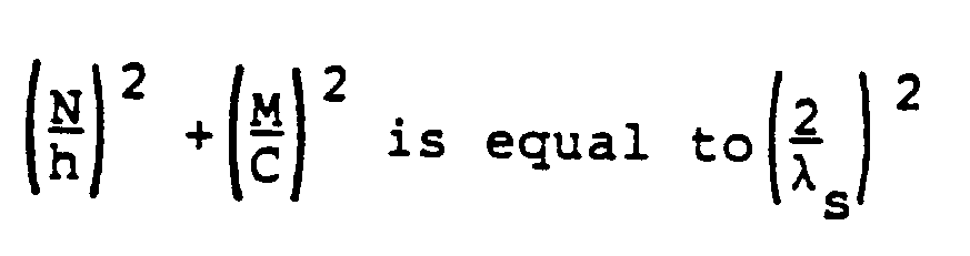
In this relationship, "h" is the height of theshield 4, "C" is the circumference of the shield 4', "λs" is the wavelength of the microwaves, and "N" and "M" are each integers, (for example, 0, 1, 2, 3, 4, etc.). - Arcing is most likely with odd multiples of "M", for example, M = 1, 3, 5, 7, etc. This may be explained with reference to FIGURE 25. At a resonant half wavelength, the voltages at the ends 35 of a conductive strip 36 have opposite polarities. Similarly, the voltages at the ends 35 of a strip 38 which is three half wavelengths will have opposite polarities. The voltages at the ends 35 of a
strip 40 which is five half wavelengths will also be of opposite polarities. Thus, the greatest electrical potential difference between the ends 35 of aconductive strip 36, 38 or 40 exists when thestrip 36, 38, or 40 is an odd multiple of a half wavelength. If, for example, the three half wavelength strip 38 is wrapped around acontainer 3 to form a shield 4' as shown in FIGURE 4, the ends 23 of the shield 4' will have opposite polarity voltages induced therein, and arcing will likely be a significant problem. - When a conductive strip 37 resonates at a full wavelength, as shown in FIGURE 25, the ends 35 of the strip 37 will have voltages of the same polarity. Similarly, when a conductive strip 39 is an even multiple of a half wavelength, voltages of the same polarity will be induced at the ends 35 of the strip 39. If the conductive strip 39 is wrapped around a
container 3 to form a shield 4', as shown in FIGURE 4, the voltages on theends 23 of the shield 4' will have the same polarity. Because like charges repel, arcing is not as likely in this instance. However, other problems associated with resonance, such as localized overheating, melting, scorching, etc., may occur and are likely to be severe. - A non-arcing non-resonant shielded
container 3 may be satisfactorily produced where the shield 4' is selected so that:
Moreover, the conductive top 5 is preferably selected so that the diameter of the top is substantially not equal to any integer multiple of the half wavelength of the microwaves. - One way of expressing substantial inequality of the equation given above is that:

for all integer values of N and M. A more preferred range is provided where:
An even more preferred range is provided where:
An especially preferred range is given where:
FIGURE 5 illustrates resonant geometries of the non-overlapping shield 4' which should be avoided. For the expression:
the graph of FIGURE 5 illustrates geometries of a generally cylindrical non-overlapping shield 4' which are susceptible to arcing. The graph assumes a microwave frequency of 2450 MHz. All dimensions on the graph are expressed in multiples of 2.54 cm (inches). - The lines drawn on the graph of FIGURE 5 illustrate a series of points where:

In order to avoid arcing, combinations of shield 4' height "h" and diameter "D" which fall upon any line shown in the graph of FIGURE 5 should be avoided. The lines drawn on the graph of FIGURE 5 illustrate combinations of shield 4' height "h" and diameter "D" which are resonant at a typical microwave frequency of 2450 MHz. Points falling on these lines are to be avoided because those points represent instances where resonances may occur in the shield 4'. For example, the shield 4' could resonate in the direction of its height "h", and also in the direction of its circumference "C" (equal to πD), if the geometry of the shield 4' is selected so that the height "h" and diameter "D" fall upon one of the curved lines in FIGURE 5. - The graph of FIGURE 5 may be adjusted for end effects, etc. which affect the actual resonant wavelength λs for the shield 4'. The actual resonant wavelength λs for a particular material used for the shield 4' may be determined empirically, as will be explained more fully below. For example, if the resonant half wavelength for the actual material used for the shield 4' is 5.0 cm (2.0 inches) instead of 5.3 cm (2.1 inches), the first horizontal line on the graph of FIGURE 5 would be shifted down slightly. Similarly, the actual resonant wavelength λs could shift the Vertical lines to the left, (or to the right). The shape of the graph, however, should remain basically the same.
- The graph of FIGURE 26 provides further experimental data for selecting a preferred circumference "C" of a non-overlapped shield 4'. This graph shows experimental results for 1.2 cm (one-half inch) wide strips of foil, and plots severity of arcing as a function of the circumference of a shield. Conceptually, FIGURE 26 may be thought of as an experiment corresponding to the dotted
line 41 shown in FIGURE 5 for a shield height "h" equal to 1.2 cm (one-half inch). The worst arcing occurs at odd multiples of a half wavelength. This corresponds to points where the dottedline 41 of FIGURE 5 crosses the solid vertical lines. The results plotted in FIGURE 26 also show arcing can be quite severe if resonance is approached. - FIGURE 27 is a graph illustrating the effects of heating upon a non-overlapped shield 4', having a constant height "h of 1.2 cm (one-half inch), as a function of the circumference "C" of the shield 4'. Even though arcing may not occur at even multiples of a half wavelength, (as shown by FIGURE 26), the experimental data plotted in FIGURE 27 shows that heating will occur at even multiples of a half wavelength.
- The experiment plotted in FIGURE 27 used several strips of metal foil having various lengths which were formed into loops having various circumferences. The metal strip was adhesively attached to a strip of lossy material, such as cardboard. A strip of temperature indicating material was affixed so that it overlaid the length of the metal strip. Suitable temperature indicating material includes cellulose acetate, which is a clear plastic-like material that turns dark when its temperature exceeds 93°C (290° F). The graph of FIGURE 27 plots the percentage of the temperature indicating strip which exceeded 143°C (290° F), and thus turned dark.
- FIGURE 27 shows that substantial heating occurred at both even and odd multiples of a half wavelength. Such heating is undesirable, and can cause melting of the package, scorching of the package or food product, localized overheating of the food product, and other undesirable effects. The peaks on the graph of FIGURE 27 correspond generally to the points where the dotted
line 41 on FIGURE 5 crosses the solid vertical lines, (although FIGURE 27 plots circumference and FIGURE 5 plots diameter). The geometry of the shield 4' should be selected to avoid these peaks of heating. - Returning now to a discussion of the preferred embodiment of the
shield 4 illustrated in FIGURE 3, significant advantages are realized by overlapping theends 23 of theshield 4. The overlappingportion 26 of theends 23 of theshield 4 effectively form parallelconductive plates 26 separated by adielectric material 25. As shown in more detail in FIGURE 3A, the ends 23 of theshield 4 in effect form a capacitor withdielectric material 25. It is believed that this capacitance tends to electrically dampen some resonant voltages which might otherwise tend to cause arcing. Theshield 4 forms a loop, as shown in FIGURE 3, which has some inductance. Thus, a "tuned circuit" can be formed with theshield 4 by carefully selecting the shield geometry. By adjusting the geometry of theshield 4, the "tuned circuit" effectively formed by the overlappingshield 4 may be tuned to control the tendency of microwaves of a particular frequency to cause arcing by inducing voltages in theshield 4. The "tuned circuit" effectively formed may also be tuned to control other undesirable effects of resonance. - The overlapping
shield 4 illustrated in FIGURE 3 tends to eliminate arcing that occurs at odd multiples of half wavelengths of the microwave radiation. The voltages induced on the overlapping ends 23 of theshield 4 will be of opposite polarity. But the overlapping ends 23 effectively form a capacitor. As long as the field strength across the capacitor does not exceed the breakdown voltage of the capacitor, the capacitor formed by the overlapping ends 23 of theshield 4 will not allow arcing. The capacitor effectively formed will store and release a charge resulting from the induced currents. Thedielectric material 25 and separation distance "d" may be selected to provide a sufficiently high breakdown voltage. The greater the distance "d", the larger the breakdown voltage. - It is believed that the polarity of the instantaneous electrical voltage which may be induced on the
ends 23 of theshield 4 in response to microwave radiation will be the same for full wavelength multiples of resonant dimensions. Due to the same polarity, and the phenomenon that like charges repel, arcing is believed to be avoided for full wavelength multiples of the circumference "C" of theshield 4. Overlapping theends 23 of theshield 4 in the manner described effectively eliminates the problem of arcing which would otherwise occur at odd multiples of a half wavelength; (see, for example, FIGURE 26). - This may be explained in more detail with reference to FIGURE 25. At odd multiples of a half wavelength, resonant voltages induced in a
metal shield 4 have opposite polarities on the ends of the metal strip. When the strip of metal is formed into a non-overlapping loop 4', as shown in FIGURE 4, the maximum potential to arc is created. Overlapping theends 23 of theshield 4, as shown in FIGURE 2, eliminates the problem of arcing at odd multiples of a half wavelength. This technique alone will substantially eliminate arcing, provided a resonant shield height "h" is avoided. This is illustrated graphically in FIGURE 28. FIGURE 28 shows that no arcing will occur with an overlappingshield 4. This may be compared with FIGURE 26, showing the results for a non-overlapped shield 4'. The overlappedshield 4 eliminates arcing at odd multiples of a half wavelength. - Applicant has discovered that a non-arcing shielded
package 21 may be satisfactorily produced from a generallycylindrical container 3 where apreferred overlapping shield 4 is provided having a geometry selected so that:
One way of expressing substantial inequality of the equation given above is that:
for all integer values of N and M. A more preferred range is provided where:
An even more preferred range is provided where:
An especially preferred range is given where:
The expression (

- FIGURE 6 illustrates resonant geometries of the
shield 4 which should be avoided. For the formula:
the graph of FIGURE 6 illustrates geometries of a generally cylindrical overlappingshield 4 which are susceptible to arcing. The graph assumes a microwave frequency of 2450 MHz. All dimensions on the graph are expressed in multiples of 2.54 cm (inches). - The advantage of an overlapped
shield 4 are further illustrated by comparing FIGURE 6 with FIGURE 5. The vertical lines representative of odd multiples of half wavelengths in FIGURE 5 are eliminated from FIGURE 6 due to overlapping. Similarly, every other curved line in FIGURE 5 is eliminated from FIGURE 6. - The line drawn on the graph of FIGURE 6 identified with
reference numeral 7 illustrates the example solution to the above formula where N = 1 and M = 0. The line illustrated and identified byreference number 8 illustrates the example where N = 2 and M = 0. Similarly,line 9 illustrates the solution for the equation where N = 0 and M = 1.Line 10 illustrates the solution for the equation where N = 0 and M = 2.Line 11 represents points where N = 0 and M = 3.Line 12 illustrates graphically the instances of acylindrical shield 4 where N = 0 and M = 4. - The curve illustrated in FIGURE 6 and identified by
reference numeral 13 illustrates the solution for the equation where N = 1 and M = 1.Curve 14 shows examples where N = 1 and M = 2. Similarly, curve 15 shows examples of acylindrical shield 4 where N = 1 and M =3. - The graph of FIGURE 6 also applies to
frustoconical shields 4 where "D" represents the mean diameter of theshield 4. Alternatively, theshield 4 should not have any diameter within the range of minimum to maximum diameters which falls upon any point onlines - To avoid problems associated with resonance, shield geometries with combinations of heights and diameters which correspond with any point on
lines shield 4 approach theresonance lines 7 through 15 should be substantially avoided by a preselected margin of error, as illustrated in FIGURE 6 by the firstshaded areas 18. An even more preferred margin of safety is provided by avoiding combinations of height "h" and diameter "D" which fall in the second broader shadedareas 19. - Another way of more specifically describing the broader shaded
areas 19 which provides a more preferred margin of safety is to specify the approximate values of height "h" and diameter "D" which bound thearea 19, assuming a microwave frequency of 2450 MHz. In a more prefer embodiment, heights "h" within the range of 3.6 to 6.6 cm (1.4 to 2.6 inches) should be avoided. Similarly, heights "h" within the range of 8.9 to 11.9 cm (3.5 to 4.7 inches) should also be avoided. In a more preferred embodiment, diameters "D" within the range of 2.3 to 4.5 cm (0.89 to 1.79 inches) should be avoided. Diameters "D" within the range of 5.7 to 8.0 cm (2.23 to 3.13 inches) should preferably be avoided. Diameters "D" within the range of 9.1 to 11.4 cm (3.57 to 4.47 inches) should preferably be avoided. Preferably, diameters "D" within the range of 12.5 to 14.8 cm (4.91 to 5.81 inches) should also be avoided. - In other words, the geometry of the
shield 4 should most preferably be selected so that it has a combination of a height "h" and a diameter "D" which falls within theunshaded area 20 of the graph of FIGURE 6. A more preferred non-arcing package may have a height "h" within the range of 0 to 3.6 cm (0 to 1.4 inches) and a diameter "D" within the range of 0 to 2.3 cm (0 to 0.9 inch). A more preferred non-arcing package may have a height "h" within the range of 6.6 to 8.9 cm (2.6 to 3.5 inches) and a diameter "D" within the range of 0 to 2.3 cm (0 to 0.9 inch). A more preferred package may have a height "h" within the range of 0 to 3.6 cm (0 to 1.4 inches) and a diameter "D" within the range of 4.6 to 5.6 cm (1.8 to 2.2 inches). Alternatively, a more preferred package may have a height "h" within the range of 0 to 3.6 cm (0 to 1.4 inches) and a diameter "D" within the range of 7.9 to 9.1 cm (3.1 to 3.6 inches). Another alternative more preferred package may have a height "h" within the range of 0 to 3.6 cm (0 to 1.4 inches) and a diameter "D" within the range of 11.2 to 12.4 cm (4.4 to 4.9 inches). - A more preferred non-arcing package with an overlapping
shield 4 may have a height "h" within the range of 6.6 to 8.9 cm (2.6 to 3.5 inches), and a diameter "D" within the range of 4.6 to 5.6 cm (1.8 to 2.2 inches). In this particular example, combinations of height "h" and diameter "D" should be avoided where
Alternatively, the shadedarea 18 around thecurve 13 should be avoided as illustrated in FIGURE 6. - In yet another more preferred embodiment the package may have a height "h" within the range of 6.6 to 8.9 cm (2.6 to 3.5 inches), and a diameter "D" within the range of 7.9 to 9.1 cm (3.1 to 3.6 inches). In such a package, the combination of the height "h" and the diameter "D" should be selected so that

Alternatively, the shadedarea 18 illustrated around thecurve 14 shown in FIGURE 6 should be avoided. - A more preferred package may alternatively have a height "h" within the range of 6.6 to 8.9 cm (2.6 to 3.5 inches) and a diameter "D" within the range of 11.2 to 12.4 cm (4.4 to 4.9 inches). Combinations of height "h" and diameter "D" should be selected such that
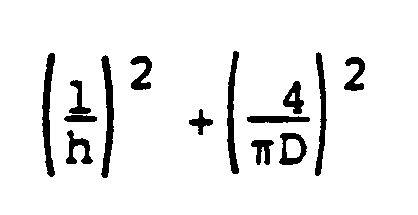
is not equal to any value within the range of ± 10% of
and
is not equal to any value within the range of ± 10% of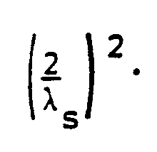
Alternatively, the shadedarea 18 around thecurves 14 and 15 illustrated in FIGURE 6 should preferably be avoided. - Of course, the diameter "D" of the shield and the circumference "C" of the shield are related by the relationship C = πD. Thus, it will be appreciated that the relationship between the height, diameter and wavelength and the relationship between the height, circumference and wavelength are equivalent.
- All of the above examples have been described with reference to a generally
cylindrical shield 4 with an overlap. The above discussion also applies to a generally frustoconical shield 4' with an overlap as shown in FIGURE 12 where the range of diameters from the smallest diameter "d₁" through the largest diameter "d₂" are all within the range specified for the diameter "D". - Reference may also be made to FIGURE 7 for heights "h" which should be avoided. FIGURE 7 illustrates graphically the severity of arcing as a function of the height of the
shield 4. The graph illustrates that the most severe arcing occurs forshield 4 heights "h" of 5.3 cm (2.1 inches) and 10.7 cm (4.2 inches). At a microwave frequency of 2450 MHz, 6.1 cm (2.4 inches) and 12.2 cm (4.8 inches) corresponds to one-half wavelength and a full wavelength "λ₀", respectively, at that frequency in free space. The resonant half wavelength in theshield 4 height "h" is about 5.3 cm (2.1 inches). The resonant wavelength "λs" for theshield 4 height "h" is about 10.7 cm (4.2 inches). The resonant wavelength "λs" for theshield 4 is related to the wavelength "λ₀" in free space by a constant factor "K". The relationship will be described in more detail below. It should be noted that the resonant dimensions for ashield 4 will not be the same as the theoretical wavelength "λ₀" in free space. FIGURE 7 shows that substantially no arcing occurred for heights "h" within the range of 6.6 to 8.9 cm (2.6 to 3.5 inches). - In the preferred embodiment utilizing Applicant's "overlapping" technique illustrated, for example, in FIGURE 3, Applicant has discovered that a relative arcing potential may be defined as:

where "D" is the diameter of the shield, "h" is the height of the shield, "L" is the distance that the first end of the shield overlaps the second end of the shield, "K" is the dielectric constant of the dielectric material between the first and second ends of the shield, "d" is the distance that the first and second ends of the shield are spaced apart, and "λ₀" is the wavelength of the microwave radiation. The arcing potential should be minimized by selecting dimensions for the shield which reduce the value of the arcing potential to a level where arcing is substantially avoided. Experiments have shown that satisfactory results may be obtained with a relative arcing potential in a range of about 0.8 to about 0. Arcing occurred for relative arcing potentials in excess of 0.8. Dimensions for an overlappingshield 4 providing a relative arcing potential of about 0.7 to about 0 give good results, and a relative arcing potential in the range of about 0.6 to about 0 provides better results. The dimensions for the shield are preferably selected so that the value for the arcing potential is in the range of about 0 to about 0.5. A range of about 0 to about 0.4 is more preferred for the arcing potential. A value for the arcing potential in the range from about 0 to about 0.3 is even more preferred. A value for the arcing potential in the range of about 0 to about 0.2 is especially preferred. A value for the arcing potential in the range of about 0 to about 0.1 is even more especially preferred. - An overlap distance "L" of about 12.7 millimeters is preferred for the overlapped
shield 4. A shield height "h" of about 75 millimeters (or about 2.95 inches) is preferred. A shield diameter "D" of about 70 millimeters (or about 2.75 inches) is preferred. - Whenever the wavelength "λs" is mentioned herein, it is to be understood that "λs" is intended to refer to the actual wavelength of the microwaves. Of course, the wavelength of the microwaves is inversely related to the frequency. As the frequency increases, the wavelength will become shorter. But the wavelength is also affected by the properties of the material through which the microwaves may travel. The wavelength of microwaves of a given frequency may be different in free space as compared with, for example, the effective wavelength in an aluminum foil shield. In free space, the wavelength λ₀ is related to the frequency "f" by the following relationship:

- Of course, the above formula provides the wavelength λ₀ in free space. The wavelength in air may be different from the wavelength λ₀ in free space. For purposes of the present invention, that difference is not significant. In other words, the wavelength λ₀ in free space is for practical purposes the same as the wavelength in air.
- For purposes of avoiding arcing due to resonant dimensions in the
shield 4, the value of λs used for the wavelength in the above relationships should be determined for the specific material used for theshield 4. The value for the actual wavelength λs may be expressed as λs = kλ₀, where λs is the actual wavelength for theshield 4, k is a correction factor, and λ₀ is the wavelength of the microwaves in free space. The correction fact k may be empirically determined. - A suitable method for determining the correction factor k involves taking strips of various lengths of the material utilized for the
shield 4. If aluminum foil is used for theshield 4, for example, various lengths of aluminum foil are cut into strips. Preferably, the strips of aluminum foil should be varied in length by increments of one millimeter, and should have a substantially uniform width. The width of the strips should not approach a resonant distance; otherwise the results of the method will be unduly complicated. A width of one-half inch is preferred. It is substantially less than a half wavelength. Therefore, complex resonances are of no concern. - The strips of aluminum foil may then be taped, bonded or otherwise affixed to a lossy material, for example, cardboard. The lossy material will be heated by the retransmitted microwave field induced by currents in the strip of aluminum foil and will assist in determining the resonant dimensions of the strips of aluminum foil. An indicator of the amount of heating is placed over the top of the strip of aluminum foil. A temperature sensitive material or temperature indicator such as cellulose acetate has been used for this purpose with good results. The various length strips are then exposed to microwave radiation for identical periods of time. Exposure times of ten seconds have given good results in practice. The extent to which the temperature indicator changes color or otherwise indicates heating may then be observed and quantified to determine the length of foil which heats the most, and therefore is the resonant length of foil. The cellulose acetate temperature sensitive material indicates resonance by turning black in response to heating. The length of strip which provides the maximum relative indication of heating is considered to be the resonant length of aluminum foil. In experiments of this type, it has been found that when a resonant length of an aluminum foil strip is tested, the cellulose acetate indicator will typically turn completely black. The resonant length is measured. The correction factor "k" is then determined by dividing the actual resonant length as measured, i.e., determined empirically, by the theoretical wavelength in free space.
- The correction factor "k" is believed to be affected by the resistivity of the material used to form the
shield 4, and by end effects. The correction factor "k" may also be affected by stray capacitances, and the dielectric properties of the materials around theshield 4; however, these latter factors are not believed to be significant. The thickness of theshield 4 does not appear to have a significant effect upon the correction factor "k", for a typical range of thicknesses. - End effects are more pronounced at smaller multiples of a half wavelength, i.e., for small integer values of "N" and "M" in the above equations. For example, aluminum foil was tested, and resonant lengths were measured and the correction factors "k" were determined. The following results were obtained:
wavelength k factor 1/2λ 0.69 1λ 0.86 3/2λ 0.88 2λ 0.88 3λ 0.87 4λ 0.90 - End effects appear to have the most effect for one-half wavelength, which yielded a "k" factor of 0.69. The "k" factor tends to generally increase for larger multiples of wavelengths, approaching a limiting value of 0.90. The slight reduction in the "k" factor observed above for 3λ is within the range of experimental error.
- The correction factor "k" may vary depending upon the material. Metallized mylar susceptors were tested for resonance, and yielded a "k" factor of 0.29 for one-half wavelength, 0.27 for one wavelength, and 0.31 for one and one-half wavelengths.
- Another aspect of resonance which should be briefly mentioned involves the phenomenon of "retransmitted fields." While arcing has been recognized in the art as a significant problem, retransmitted fields induced in the
shield 4 at resonance can cause localized overheating, scorching, melting, and other problems. - The shield's exterior geometry is not the only concern for effective differential heating using a
conductive shield 4. If the interior dimensions of a shieldedcontainer 3 resonate at the microwave frequency, undesirable heating of thefood substances shield 4 are properly selected, theshield 4 may function as a waveguide. Theshield 4 if it behaves as a waveguide, may control the direction of the microwaves entering the package in the interior of thecontainer 3, which tend to heat thefood material 2. The effective wavelength of microwaves in thefood materials - In a preferred embodiment, attention must be given to the effective wavelength of the microwaves in the
food substances container 3. For purposes of discussion, we may refer to the effective wavelength of microwaves in the food substance held within thecontainer 3, such as theice cream 2, as "λ₁". The wavelength λ₁ will be affected by the properties of thefood substances container 3. Eachfood substance food substances food materials food substance 2 should be selected to avoid resonances which would induce undesired heating of theice cream 2. - The dielectric properties of a
food substance 1 may be measured using techniques which are known in the art. For example, a Hewlett Packard 8753A microwave network analyzer may be used. Once the dielectric of thefood substance ice cream 2, it may sometimes be necessary to account for the differences in the wavelength λ₁ in thefood substance 2 immediately adjacent theshield 4 to the extent that the wavelength λ₁ is different from the wavelength of the microwaves in free space. In such instances, the dimensions of thecontainer 3 may need to be-adjusted in view of the actual wavelength λ₁ in thefood substance 2 within thecontainer 3, which will determine the resonant dimensions for thefood substance 2. - In a preferred embodiment, the
brownie 1 characteristics should be selected to enhance absorption and thesauce 6 characteristics should be selected to enhance reflectance. - The
sauce 6 preferably has characteristics which cause it to function as an edible reflective layer. If thesauce 6 has a high impedance relative to a low impedanceice cream layer 2 and a lowimpedance brownie layer 1, this low impedance/high impedance/low impedance interface enhances the action of thesauce 6 as a reflective layer. If the thickness of thesauce layer 6 is selected to be about one-half wavelength thick, constructive interference will be enhanced between microwaves reflected on both interfaces between thesauce 6 and theice cream 2, and between thesauce 6 and thebrownie 1. Reflection of microwaves back to thebrownie 1 will be enhanced. This will have a favorable effect upon the temperature differential between thebrownie 1 and theice cream 2. Enhancing reflection will reduce the amount of microwaves which reach theice cream 2. - Absorption of the
brownie 1 may be optimized or enhanced by considering the dielectric loss factor (E'') of thebrownie 1. Reflectance of thesauce layer 6 may be enhanced by considering the index of refraction. - In summary, the temperature differential between the
brownie 1 and theice cream 2 may be enhanced or optimized by considering layer thickness, layer diameter, and dielectric properties of thebrownie 1,ice cream 2 andsauce 6 layers. - The preferred dielectric properties for the
ice cream 2 are a value of dielectric constant (E') = 5.96 and a value of dielectric loss factor (E'') = 2.51. Theice cream 2 should have a diameter of about 72 mm and a thickness of about 48.5 mm. The preferred dielectric properties for thebrownie 1 are a value of E' = 3.03 (dielectric constant) and a value of E'' = 0.67 (dielectric loss factor). Thebrownie 1 should have a diameter of about 72 mm and a thickness of about 14.5 mm. The preferred dielectric properties for thesauce 6 are a value of E' = 8.41 (dielectric constant) and a value of E'' = 4.89 (dielectric loss factor). Thesauce 6 should have a diameter of about 72 mm and a thickness of about 9 mm, and should be placed between thebrownie 1 and theice cream 2 in a generallycylindrical container 3 having a diameter of 72 mm and a total container height of about 81.5 mm. - A recessed lid or top 5 is preferably provided which is recessed about 9.5 mm, as shown in FIGURE 1. The recessed
top 5 is formed from a conductive material or covered by a conductive material, and effectively prevents microwaves from entering the top of thecontainer 3. The gap between the top 5 and theshield 4 is small enough to prevent leakage of microwaves. The recessed design for thelid 5 also places theedges 33 of thelid 5 at a position remote from the shieldedfood material 2. If thelid 5 approaches resonance, voltage nodes or retransmitted fields which occur at the edges of thelid 5 will be spaced from theice cream 2 to minimize or reduce the heating effect upon theice cream 2. - The conductive top 5 preferably is circular, and has a diameter "dT". The diameter "dT" is selected so that:

is substantially not equal to
where "N" and "M" are integers, for example, 0, 1, 2, 3, 4, etc., and "λT" is the actual resonant wavelength of the microwaves in theconductive top 5. - For a rectangular top having a length "lT" and a width "wT", the dimensions are selected so that:

- A conductive
aluminum foil shield 4 should be provided with a preferred height of about 75 mm. An exposedwall 24 at the bottom of thecontainer 3 is provided over the lower 6.35 mm of thecontainer 3 in the illustrated embodiment. Asmall rim 27 at the top of thecontainer 3 of about 0.15 mm would not be covered by theshield 4. In practice, it has been found that anunshielded rim 27 of 1.6 mm (1/16 inch) or more will usually allow leakage of microwaves to occur into the shieldedzone 2. - The
shield 4 preferably serves as a label for thepackage 21. Theshield 4 may be imprinted with labeling information and bonded or adhesively affixed to the package in a conventional manner. - If desired, the
shield 4 could be formed, e.g., by sputter coating or electroplating, so that the shield had no seam or gap, but instead formed a continuous conductive sheet around thecontainer 3. This arrangement is not preferred because it is too costly. - For a frustoconical container 3', as shown in FIGURE 12, an
ice cream 2 thickness of about 3.0 centimeters is preferred. Abrownie 1 thickness of about 1.8 centimeters is preferred. Asauce 6 thickness of about 0.6 centimeters is also preferred. - FIGURE 10 illustrates the results of experiments upon a variety of
cylindrical containers 3 havingshields 4 wrapped around thecontainers 3. The cylinders were tested for hot spots by coating the package with cellulose acetate. The particular cellulose acetate compound employed turned dark at 143°C (290° F). The graph of FIGURE 10 illustrates the amount of blackening that occurred over the aluminum foil shieldedcylinder 3, as observed by the reaction of the acetate material to heating. This experiment provided further information concerning the susceptibility of the package to adverse effects of resonance, retransmitted fields, and arcing. This graph may be used as a basis for selecting a favorable combination of dimensions for a package. - FIGURE 11 illustrates the amount of arcing for various heights and circumferences in a cylindrical shield constructed from aluminum foil. The test was conducted at 2450 MHz. Approximately 140 different cylinders were tested, and the amount of arcing was rated or scored as follows: 0 = no arcing at all; 1 = a single spark was observed; 2 = intermittent sparking; 3 = continuous sparking; and 4 = the package started on fire. This experiment indicated that the most severe arcing occurred where the height of the foil was equal to approximately 5.3 cm (2.1 inches) and approximately 10.6 cm (4.2 inches).
- A suitable alternative embodiment of a frustoconical container which has given satisfactory results in practice is shown in FIGURE 13 and FIGURE 14. The indicated dimensions are in inches. This particular container 3' has a 7° taper on its side walls, thereby forming a frustoconical container 3'. A frustoconical shield 4' would be formed around the walls of the container 3', as illustrated in FIGURE 12. The shield height "h" is measured parallel to the surface of the shield 4'.
- FIGURE 15 and FIGURE 16 illustrate a suitable top 5' for the container 3'. The dimensions are in inches.
- A suitable shield 4' is illustrated in FIGURE 17. For the frustoconical container 3' illustrated in FIGURE 13, the shield 4' is formed as illustrated in FIGURE 17. The shield has a mean circumference "C". The shield 4' has a minimum circumference "C₁" and a maximum circumference "C₂", with "C₂" being the largest value in the range of circumferences. The
portion 26 of the shield 4' which overlaps is not included in the measurement of the effective circumference "C" of the shield 4'. - In the case of a tapered container 3', or frustoconical container 3', the circumference "C" of the shield 4' varies over a range, being larger near the top 5' of the container 3' and smaller near the bottom of the container 3'. The mean circumference "C" of the shield 4' may be measured at the-enter of the shield 4' in the illustrated example of FIGURE 12. The shield 4' will also have a mean diameter "D" when it is wrapped around the container 3'. The shield 4' will have a minimum diameter "d₁", which in the illustrated embodiment shown in FIGURE 12 is measured at the bottom of the shield 4'. The shield 4' will have a maximum diameter "d₂", which is measured at the top of the shield 4' in the illustrated embodiment.
- When selecting a frustoconical shield 4', a range of diameters "d₁" through "d₂" and a range of circumferences "C₁" through "C₂" must be considered. The above discussion with respect to cylindrical shields applies to a frustoconical shield 4' except that a mean circumference "C" and mean diameter "D" should be considered, and preferably arcing will be avoided for any diameter with the range "d₁" through "d₂", and for any circumference within the range "C₁" through "C₂".
- In this particular alternative embodiment, the dimensions have been selected to optimize the temperature differential for the
food materials - The "air gap" technique is another technique for avoiding detrimental effects of retransmitted microwave fields. It involves the use of
air gaps 16 near the edges of the shield 4'. This may be best understood by referring to the graph shown in FIGURE 18. In this example, where there is no gap between thebrownie 1 and the bottom of the container 3', a maximum voltage equal to 10,000 volts is assumed at the edge of the shield 4', indicated generally by the reference "MX" in FIGURE 18. A computer-generated electric field is illustrated for a shielded container 3'. In the close-up of the maximum voltage region "MX" shown in FIGURE 19, a field line equal to 6,000 gauss is shown going through thebrownie 1. Thus, high strength fields are present in thebrownie 1, and may cause heating of thebrownie 1. If the heating effect upon thebrownie 1 is too severe, it may adversely affect both thefood material 1 and the container 3'. Thefood material 1 may be scorched, thefood material 1 may be overheated near the lower edge of the shield 4', the container 3' may be melted near the lower edge of the shield 4', and in extreme cases such heating can even cause burning of the container 3'. - FIGURE 20 illustrates the effect of an
air gap 16 upon the computer-generated graph of electrical field strength. Thegap 16 is an air gap formed between thefirst food material 1, (i.e., the brownie 1), and the side wall of the container 3'. In this case, the strongest portion of the electrical field appears in theair gap 16, and does not contribute to heating of thebrownie 1. A close-up view of this graph is shown in FIGURE 21. The field lines of 6,000 gauss and even 4,000 gauss cut through theair gap 16. The field line of 2,000 gauss barely cuts through the surface of thebrownie 1. Thus, the tendency of thebrownie 1 to become overheated in this region is greatly reduced. In other words, the high field strength generated near the edge of the shield 4' at the maximum voltage point "MX" does not overheat thebrownie 1 due to the presence of theair gap 16. - In the example illustrated in FIGURE 19, the field line of 6,000 gauss cuts substantially into the depth of the
brownie 1 and contributes substantially to the heating of thebrownie 1. By comparison, in the example illustrated in FIGURE 21, the field line of 6,000 gauss cuts through theair gap 16 without any substantial heating effect upon thebrownie 1. - FIGURE 22 illustrates a computer-generated graph for the electrical field strength where the
air gap 16 is 1/8 inch. Even more of the electrical field strength surrounding the maximum "MX" cuts through theair gap 16. This is shown by the close-up illustration of FIGURE 23. In this example, even the field lines representing a value of 2,000 gauss do not cut through the surface of thebrownie 1. - The air gap technique may be utilized in instances where the height "h" of the
shield 4 approaches a resonant length. - Although the above discussion has referred to this technique as the "air gap technique", the same principle will work with any low loss, low
dielectric material 16 immediately adjacent to the edge of the shield 4'. Air is the preferred material, and the most convenient. - FIGURE 24 illustrates an alternative embodiment of a container 3'' which utilizes the air gap technique to minimize overheating of the food material in the bottom of the container 3''. This container 3'' uses air gap means 16' to avoid overheating of the container 3'' if the shield 4'' dimensions approach resonance sufficiently to realize substantial fields at the lower edge 30'' of the shield 4''. The container 3'' has a lower shoulder or rim 17 which forms an air gap 16' between the bottom 22'' of the container 3'' and the lower edge of the shield 4''. The bottom 22'' is preferably flat in the center and tapers upwardly over a recessed region 28'' to adjoin the sidewall 29'' of the container 3'' at a point 31'' remote from the lower edge 30'' of the shield 4''. The shield 4'' is wrapped around the outside of the sidewalls 29'' of the container 3''.
- Alternatively, an
air gap 16 may be formed as in FIGURE 20 by cooking thebrownie 1 in a container having a taper which is larger than the taper of the container 3'. This is not the preferred method for utilizing the air gap technique, because thesauce 6 may melt and fill theair gap 16 and thus defeat the benefits of the air gap technique. - The use of a tapered container 3' as shown in FIGURE 12 and FIGURE 13 allows the selective use of resonant dimensions to improve the temperature differential between the
first food material 1 and thesecond food material 2. A tapered container 3' allows the package to be designed to have a single horizontal diameter, for example d₁, which resonates at the point where thefirst food material 1 is desired to be heated. Other diameters, i.e., the diameters of the container 3' corresponding to the location of thesecond food material 2 in the range from d₂ to d₃ shown in FIGURE 12, are selected to be nonresonant diameters. Thus, the resonant diameter d₁ at the lower edge of the shield 4', corresponding to the position of thebrownie 1, assists in heating of thebrownie 1, while the diameters of the shield 4' in the area of the container 3' where theice cream 2 is located in the range from d₂ to d₃ are nonresonant. - Optimum performance of a shielded food package when heated by microwave radiation can also be affected by standing waves within the microwave cavity of the microwave oven. Product performance may be enhanced by utilizing standing waves generated between the floor of the oven and the
food material 1 in thecontainer 3. Not only is the brownie diameter (for example d₁) important, but the brownie thickness is also important. If the distance between the floor of the microwave oven and the shelf containing the package is approximately 1.2 inches, this will be equal to about one-quarter wavelength of the microwaves in air, (which is virtually the same as in free space). In this example, thebrownie 1 should preferably be made 1.8 cm ( 0.7 inch) thick, (i.e., thebrownie 1 height equals about 1.8 cm (0.7 inch)). This is because the one-quarter wavelength of the microwaves in question in thebrownie material 1 is about 1.8 cm (0.7 inch) due to the particular properties of thebrownie 1. This construction is especially effective if a highlyreflective sauce 6 is interposed between thebrownie 1 and theice cream 2. Sauce layers 6 capable of reflecting 60-80% of the microwave energy back down to thebrownie 1 are theoretically attainable. - A tapered container 3' as shown in FIGURE 12 also provides some tolerance, so that if the shield 4' does resonate for a particular diameter dn, the shield 4' will not resonate over its entire length "h", but will only resonate in one horizontal plane. This provides some tolerance for the construction of the package, which is a desirable attribute for a package intended for home use where microwave ovens may vary.
- The
brownie 1 may be baked in a pan of suitable size and transferred to thecontainer 3 for packaging. Alternatively, cost savings may be realized by breaking thebrownie 1 into pieces and packing the pieces into the bottom of thecontainer 3. - The
shield 4 should preferably have a height "h" within the range of 6.1 to 9.1 cm (2.4 inches to 3.6 inches). A range of heights "h" for theshield 4 between 6.4 to 8.9 cm (2.5 inches to 3.5 inches) is more preferred. An even more preferred range of heights "h" is between 6.6 to 8.6 cm (2.6 inches to 3.4 inches). Ashield 4 height "h" between 7.1 to 8.1 cm (2.8 inches to 3.2 inches) is especially preferred. There is apparently no significant effect upon the preferred height "h" of theshield 4 where thecontainer 3 is a cylindrical container, as illustrated in FIGURE 1, as compared to a frustoconical container 3', as illustrated in FIGURE 12. - The diameter "D" for the
shield 4 should preferably be within the range of 7.1 to 9.1 cm (2.8 inches to 3.6 inches). An even more preferred diameter "d" for theshield 4 is in the range of 7.4 to 8.6 cm (2.9 inches to 3.4 inches). A diameter "D" for theshield 4 within the range of 7.6 to 8.1 cm (3.0 inches to 3.2 inches) is especially preferred. - For an overlapping shield, as illustrated in FIGURE 3, an overlapping distance "L" of about 1.2 cm (1/2 inch) may provide satisfactory results. An overlapping distance "L" within the range of 0.13 to 3.8 cm (0.05 inch to 1.5 inches) is preferred. An amount of overlap "L" of 0.25 to 3.8 cm (0.1 inch to 1.5 inches) is more preferred. An amount of overlap "L" within the range of 1.2 to 3.8 cm (0.5 inch to 1.5 inches) is especially preferred.
- Where the frequency of a microwave oven is 2450 MHz, the wavelength λ₀ will be known. In such an instance, the expression DhLK ÷ 4dλ₀² may be simplified to DhLK ÷ 92.16d.
- Referring to FIGURE 1, the thickness of the
brownie layer 1 is preferably 14.5 millimeters. A thickness for thebrownie layer 1 within the range of about 11 millimeters to about 18 millimeters will provide satisfactory results. A thickness for theice cream layer 2 within the range of about 40 millimeters to about 57 millimeters is preferred. A thickness for theice cream layer 2 within the range of about 43 millimeters to about 54 millimeters is more preferred. A thickness for theice cream layer 2 equal to about 48.5 millimeters is especially preferred. Thesauce layer 6 may have a thickness between about 8 millimeters and about 10 millimeters. A thickness of about 9 millimeters for thesauce layer 6 is preferred. - In a preferred embodiment, the
shield 4 is formed by wrapping a single piece of aluminum foil around thecontainer 3. However, if desired, theshield 4 may be constructed from two or more pieces of aluminum foil. Each piece of aluminum foil may overlap the adjoining piece, as shown in FIGURE 3 for a one-piece label 4. The use of a plurality of labels appears to provide equivalent results, and appears to behave substantially the same as a one-piece shield 4. - In an experiment to compare varying amounts of overlap "L", strips of foil were formed into loops. A length of foil forming a loop one and one-half wavelengths in circumference was utilized. This loop was then wrapped around a paper cylinder, which was used as a lossy material to be heated by the regenerated fields induced in the foil. A temperature sensitive transparent paper was then placed over the foil to mark the location of the areas of the foil strip which exceeded 143°C (290° F). Cellulose acetate was used as the temperature sensitive transparent material. The strip was microwaved for 10 seconds. The following table summarizes the results, where the column marked "% Burn" represents the percent of the temperature sensitive material which turned dark (as a result of exceeding 143°C (290° F)).
Overlap Capacitance Relative Arcing Potential Arcing % Burn 0 0 F 1.00 X 60% 0.02 1.4 x 10⁻¹²F .93 X 54% 0.05 3.6 x 10⁻¹²F .86 36% 0.10 7.1 x 10⁻¹²F .74 27% 0.2 1.4 x 10⁻¹¹F .63 25% 0.5 3.6 x 10⁻¹¹F .46 16% - Arcing occurred where the amount of overlap was 0 or 0.5 mm (0.02 inch). Where the overlap was 1.3 mm (0.05 inch) or greater, no arcing occurred. In other words, where the relative arcing potential was equal to .86 or less, no arcing occurred. In summary, without an overlap, or with a slight overlap, the test strips arced and the transparent temperature sensitive paper darkened. With a larger overlap, arcing was eliminated and the retransmitted fields were reduced.
- Foil loops of different circumferences were tested in the method described above. A one-half inch overlap was used with these loops. None of the loops arced and resonances only occurred at multiples of a full wavelength, where potential differences do not exist across the capacitor formed by the overlapping ends of the shield. The results of this experiment are summarized in FIGURE 9. The effect of the amount of overlap "L" upon the relative arcing potential is summarized in FIGURE 8.
Claims (62)
- A method of substantially eliminating arcing in a food container for a microwave environment, where a food container (3) is provided having a food material (1,2) to be heated by microwave radiation and to be at least partially shielded from microwave radiation, and a conductive shield (4) is provided having a first end and a second end, characterized by the steps of:
providing the conductive shield around a part of the food container, the conductive shield being located in microwave shielding relationship to a portion of the food material, the conductive shield having a height and circumference;
overlapping the first end (23) of the shield (4) over the second end (23) of the shield to form an overlapped shield, where the first and second ends of the overlapped shield are separated by a dielectric material (25), the amount of the overlap being selected to damp potential arcing currents; and,
selecting the height (h) and circumference (C) of said shield to be not equal to any multiple of a half wavelength of the microwave radiation in the shield thereby avoiding resonance of the shield to minimize arcing. - The method according to claim 1, further characterized in that the dimensions of the shield are selected to reduce the relative arcing potential to a level where arcing is substantially avoided, the relative arcing potential being defined by:
 D is the diameter of the shield (4)h is the height of the shield (4)L is the distance that the first end (23) of the shield overlaps the second end of the shield (23)K is the dielectric constant of the dielectric material (25) between the first and second ends of the shield,d is the distance that the first and second ends (23) of the shield are spaced apart,λ₀ is the wavelength of the microwave radiation; and,reducing the relative arcing potential by selecting dimensions for the shield which reduce the value of the reflective arcing potential to a level where arcing is substantially avoided.
 - The method according to claim 1, further characterized in that the conductive shield is generally formed into an electrical loop.
- The method according to claim 2, further characterized in that the values D, h, L and d are given in inches and 4λ₀² takes on the value of 92.16.
- The method according to claim 1 or 2, further characterized in that said food container (3) and said conductive shield (4) are generally frustoconical in shape and said diameter D is the mean diameter of the frustoconical-shaped shield.
- The method according to any of the claims 2 to 5, further characterized in that the step of reducing the relative arcing potential is sufficient to produce a value for the relative arcing potential in one of the following ranges with increasing preference:
- The method according to any of the claims 1 to 6, further characterized by:
providing a conductive top (5) to seal the food container (3), the conductive top being in microwave shielding relationship with the shield, the conductive top having a diameter "dT", the diameter of the top being selected so that:
- The method according to claim 7, further characterized by:
recessing the conductive top (5) into the container, so that edges (33) of the conductive top are located remote from the portion of food material (2) to be shielded, whereby the heating effect of fields induced in the edges of the conductive top upon said portion of food material will be minimized. - The method according to claim 1 or claim 5, further characterized by:
selecting a shield (4) having a height "h" and a range of diameters from a maximum diameter "d₂" to a minimum diameter "d₁", such that:
- The method according to any of the claims 2 to 8, further characterized in that:
the height "h" of the shield and the diameter "D" of the shield are selected so that:

- The method according to any of the claims 2 to 8, further characterized in that:
the height "h" of the shield and diameter "D" of the shield are selected so that:
- The method according to claim 10, further characterized in that:
the height "h" of the shield (4) is selected to be in the range of 6,35 cm (2.5 inches) to 8,9 cm (3.5 inches). - The method according to claim 10, further characterized in that:
the height "h" of the shield (4) is selected to be in the range of 6,1 cm (2.4 inches) to 9,1 cm (3.6 inches). - The method according to any of the claims 10 to 13, further characterized in that:
the diameter "D" of the shield (4) is selected to be in the range of 7,1 cm (2.8 inches) to 9,1 cm (3.6 inches). - The method according to any of the claims 10 to 14, further characterized in that:
the portion of food material to be at least partially shielded from microwave radiation is selected to have a thickness of about 43 millimeters to about 54 millimeters to avoid resonant fields in said portion. - A method for producing a shielded container for differential heating of food material with microwave radiation, where a food container (3) is provided having a food material (1,2) to be heated by microwave radiation and to be at least partially shielded from the heating effects of microwave radiation, characterized by the steps of:
selecting a conductive shield (4') to have a height which is not equal to any multiple of a half wavelength of the microwave radiation in the shield and a circumference which is not equal to any multiple of a half wavelength of the microwave radiation in the shield, thereby avoiding resonance of the shield at the frequency of the microwave radiation to minimize arcing; and,
providing the shield (4') around the container in microwave shielding relationship to the portion of food material to be shielded to reduce the heating effect of the microwave radiation by shielding said portion and permitting differential heating of the food material in the container. - The method according to claim 16, further characterized in that said conductive shield is selected so that the shield has a height (h) which is not equal to any integer multiple of from about 5.4 centimeters to about 6.9 centimeters, and the shield has a circumference (C) which is not equal to any integer multiple of from about 5.4 centimeters to about 6.9 centimeters, thereby avoiding resonance of the shield at the frequency of the microwave radiation to minimize arcing.
- The method according to claim 16, further characterized in that said shield (4') is frustoconical in shape and is selected so that the shield has a height which is not equal to any multiple of a half wavelength of the microwave radiation, and the shield has a range of circumferences, the shield not having a circumference equal to a multiple of a half wavelength of the microwave radiation over a portion of the height of the frustoconical shield corresponding to the location of the food material to be shielded, thereby avoiding resonance of the shield at the frequency of the microwave radiation at a location which would overheat said portion.
- The method according to claim 18, further characterized by:
selecting a resonant diameter (D) for the conductive shield (4') over a section of the height of the frustoconical shield corresponding to the location of a second portion of food material to enhance heating of said second portion. - The method according to claims 18, further characterized in that:
the shield is selected so that the shield does not have a circumference (C) equal to a multiple of a half wavelength of the microwave radiation over the entire height (h) of the shield. - A package for the differential heating of food with microwave radiation, including a microwave food container (3) having a food material (1,2) to be heated by microwave radiation and to be at least partially shielded from microwave radiation and including a conductive shields (4) shielding part of the food container in proximity to the portion of food material (1) to be at least partially shielded, characterized in that:
the shield is generally electrically looped, the shield having some inductance, the shield having a first end (23) the shield having a second end (23) which overlaps the first end for a distance "L", the first end and the second end being spaced apart a distance "d", the first end and the second end being separated by dielectric material (25) having a dielectric constant "K", the shield having some capacitance, the looped shield having a diameter of "D" and a height of "h"; and,
the diameter "D" and height "h" of the shield, the amount of overlap "L" between the first and second ends of the shield, the spacing "d" between the ends of the shield, and the dielectric constant "K" of the dielectric material between the first and second ends (23) of the shield being selected to damp potential arcing currents by reducing the relative arcing potential defined by:
whereby the shield (4) is provided with a nonresonant combination of capacitance and inductance to damp potential arcing currents thereby substantially avoiding arcing. - The package according to claim 21, further characterized in that said shield is formed into a loop having inductance and said wavelength is such that 4dλ₀² takes on the value 92.16.
- The package according to claim 21 or 22, further characterized in that:
the diameter "D" and height "h" of the shield (4), the amount of overlap "L" between the first and second ends (23) of the shield, the spacing "d" between the ends of the shield, and the dielectric constant "K" of the dielectric material between the first and second ends (23) of the shield (4) are selected to produce a value for the arcing potential in one of the following ranges with increasing preference: - The package according to any of the claims 21 to 23, further characterized in that:
the diameter "D" of the shield (4) is between 7,1 cm (2.8 inches) and 9,1 cm (3.6 inches). - The package according to any of the claims 21 to 23, further characterized in that:
the diameter "D" of the shield (4) is between 7,4 cm 2.9 (inches) and 8,6 cm (3.4 inches). - The package according to any of the claims 21 to 23, further characterized in that:
the diameter "D" of the shield (4) is between 7,6 cm (3.0 inches) and 8,1 cm (3.2 inches). - The package according to any of the claims 21 to 23, further characterized in that:
the height "h" of the shield (4) is between 6,1 cm (2.4 inches) and 9,1 cm (3.6 inches). - The package according to any of the claims 21 to 23, further characterized in that:
the height "h" of the shield (4) is between 6,6 cm (2.6 inches) and 8,6 cm (3.4 inches). - The package according to any of the claims 21 to 23, further characterized in that:
the height "h" of the shield (4) is between 7,1 cm (2.8 inches) and 8,1 cm (3.2 inches). - The package according to claim 24, further characterized in that:
the height "h" of the shield (4) is between 6,1 cm (2.4 inches) and 9,1 cm (3.6 inches). - The package according to claim 25, further characterized in that:
the height "h" of the shield (4) is between 6,6 cm (2.6 inches) and 8,6 cm (3.4 inches). - The package according to claim 26, further characterized in that:
the height "h" of the shield (4) is between 7,1 cm (2.8 inches) and 8,1 cm (3.2 inches). - The package according to any of the claims 21 to 23, further characterized in that:
the amount of overlap "L" between the first and second ends (23) of the shield (4) is between 0,12 cm (0.05 inches) and 3,8 cm (1.5 inches) in particular between 0,25 cm (0.1 inch) and 3,8 (1.5 inches), and more particularly between 1,2 cm 0.5 inch and 3,8 cm 1.5 inches. - The package according to claim 27, further characterized in that:
the amount of overlap "L" between the first and second ends (23) of the shield (4) is between 0,12 cm 0.05 inches and 3,8 cm (1.5 inches), in particular between 0,25 cm 0.1 inch and 3,8 cm (1.5 inches), and more particularly between 1,2 cm (0.5 inch) and 3,8 cm (1.5 inches). - The package according to claim 27, further characterized in that:
the amount of overlap "L" between the first and second ends (23) of the shield (4) is between 0.12 cm (0.05 inches) and 3,8 cm (1.5 inches), in particular between 0,25 cm (0.1 inch) and 3,8 cm (1.5 inches), and more particularly between 1,2 cm (0.5 inch) and 3,8 cm (1.5 inches). - The package according to claim 32, further characterized in that:
the amount of overlap "L" between the first and second ends (23) of the shield is between 0,12 cm (0.05 inches) and 3,8 cm (1.5 inches) in particular between 0,25 cm 0.1 inch and 3,8 cm (1.5 inches) and more particularly between 1,2 cm (0.5 inch) and 3,8 cm (1.5 inches). - A food package for differential heating of food material (1,2) in a microwave environment including a container (3) containing a food material to be heated by microwaves and to be at least partially shielded from microwaves and a conductive shield (4'), characterized in that the shield is formed around part of the container near where the portion of food material (1) be shielded is located, the shield having a circumference (C) and a height (h), the shield having non-resonant dimensions to avoid arcing where the height and circumference are selected such that:

whereby resonance of the shield and resonant voltages at the edges of the shield are avoided to minimize arcing when the shield is exposed to microwaves; and,
the shield being operative to allow the food material to be heated by microwaves while substantially reducing the exposure of the portion of food material to the heating effects of the microwaves. - The package according to claim 37, further characterized in that said container (3) and said shield have a generally cylindrical shape.
- The package according to claim 37, further characterized in that:
said container (3) and said shield (4') have a frustoconical shape, said shield having a minimum and a maximum circumference (C₂, C₁) and said shield having nonresonant dimensions to avoid arcing where the height (h) and circumference (C) are selected such that: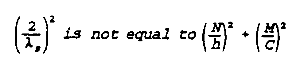
the shield (4') being operative to allow a portion of the food material (1) to be heated by microwaves while substantially reducing the exposure of a second portion of food material (2) to the heating effects of the microwaves. - The package according to the claim 38 or 39 further characterized in that:
a conductive top (5') covers the container on an end of the container near the portion of food material to be shielded. - The package according to claim 40, further characterized in that the conductive top (5') has a diameter (d₂), the top being selected so that the diameter of the top is not equal to any integer multiple of the half wavelength of the microwaves.
- The package according to any of the claims 37, 38 39, 40 or further characterized in that:
the height "h" of the shield (4') and the circumference "C" of the shield are selected so that:

- The package according to any of the claims 37 to 42, further characterized in that λs is equal to 10,7 cm (4.2 inches).
- The package according to any of the claims 37 to 42, further characterized in that:

- The package according to any of the claims 37 to 42, further characterized in that:
a conductive top having a diameter "dT" is provided to seal the container, the diameter "dT" being selected so that :
- The package according to claim 38, further characterized in - that said shield having nonresonant dimensions to avoid arcing has the height "h" and circumference "C" selected such that:

- The package according to claim 46, further characterized in that:
a conductive top (5) covers the container on an end of the container near the portion of food material (2) to be shielded. - The package according to claim 49, further characterized in that the conductive top (5) is circular and has a diameter, (dT), the top being selected so that the diameter of the top is substantially not equal to 5,3 cm (2.1 inches), or 7,5 cm (2.95 inches), or 10,7 cm (4.2) inches), or 11,9 cm (4.7 inches), or 15 cm (5.9 inches), or 16 cm (6.3 inches).
- The package according to claim 47, further characterized in that:
the conductive top has a diameter "dT", the diameter "dT" of the conductive top is selected so that:
- The food package according to claim 37, further characterized in that:
the package (21) is intended for use in a microwave oven having a frequency of 2450 MHz;
the container (3) is a generally cylindrical container, the container being essentially transparent to microwave radiation, the container having a height (h), the container having a bottom (22) and an opening remote from the bottom, the container having a diameter of about 72 millimeters;
a recessed lid (5) is provided, the lid mating with the opening in the container to sealingly engage the container, the lid having a conductive layer (4) to inhibit microwave radiation from entering the container;
the conductive shield (4) having a height of about 75 millimeters, the shield having a lower edge spaced (24) from the bottom (22) of the container, the shield having an upper edge (34) overlapping the recessed lid (5) to form a microwave resistant seal with the lid;
the food material includes a first food substance (1) filling the bottom of the container and having a thickness between about 11 millimeters and about 18 millimeters, the first food substance intended to be heated by microwave radiation;
the food material includes a second food substance (2) in the container (3), the second food substance intended to be substantially shielded from microwave radiation, the shield (3) and lid (5) substantially surrounding the top and sides of the second food substance (2);
an edible third food substance (6) is provided in the container between the first food substance (1) and the second food substance (2) the third food substance (6) having a thickness between about 8 millimeters and about 10 millimeters;
whereby the dimensions and geometry of the container, shield and food substances are selected to substantially avoid resonances and to minimize arcing. - The food package according to claim 50, further characterized in that the conductive shield (4) has overlapping ends (23) separated by a dielectric material (25) to dampen arcing voltages.
- The food package according to claim 51, further characterized in that the second food substance (2) has a thickness between about 40 millimeters and about 57 millimeters.
- The food package according to claim 52, further characterized in that the container (3) has a height (h) of about 81.5 millimeters.
- The food package according to claim 51, further characterized in that the first food substance (1) has dielectric properties including a dielectric constant E' of about 3.03 and a dielectric loss factor E'' of about 0.67.
- The food package according to claim 51 or claim 53, further characterized in that the second food substance (2) has dielectric properties including a dielectric constant E' of about 5.96 and a dielectric loss factor E'' of about 2.51.
- The food package according to any of the claims 51 to 55, further characterized in that the third food substance (6) has dielectric properties including a dielectric constant E' or about 8.41 and a dielectric loss factor E'' of about 4.89, the third food substance being generally reflective of microwave radiation.
- The food package according to claim 37, further characterized in that:
the food material includes a first food substance (1) to be heated by microwaves and a second food substance (2) to be shielded from microwaves; and,
the conductive shield (4) has an electrical loop creating inductance "l", the shield having overlapping conductive plates (26) separated by a dielectric material (25) creating capacitance "c", the amount of overlap and spacing between the conductive plates (26) being selected to reduce a relative arcing potential to substantially eliminate arcing, where:
- The food package according to claim 57, further characterized in that:
the conductive shield (4) has a height "h" which is substantially not equal to any integer multiple of a half wavelength "λs" of the actual resonant wavelength of the microwaves in the shield. - The food package according to claim 57 or 58, further characterized in that:
a recessed conductive top (5) is provided in sealing engagement with the container (3), the top being recessed where edges (33) of the top are located remote from the second food substance (2) so that electrical fields induced in the conductive top (5) by microwave radiation do not overheat the second food substance. - The method according to claim 1, further characterized by the steps of:
determining resonant lengths of the shield by constructing a laminate test strip including a length of conductive shielding material, a strip of lossy material, and a strip of temperature indicating material; and,
irradiating the laminate test strip with microwave radiation for a predetermined period of time to determine the heating response of the laminate test strip. - The method according to claim 60, further characterized in that:
a plurality of laminate test strips are constructed having a plurality of different lengths of conductive shielding material, each length of conductive shielding material being bonded to a strip of lossy material and a strip of a temperature sensitive indicator;
all said laminate test strips are irradiated with microwave radiation for a predetermined period of time; and,
evaluating relative temperature indications of the temperature sensitive indicators of the strips to determine the lengths of conductive shielding material which provide the maximum relative temperature indication. - The food package according to claim 37, further characterized in that:
the food material includes a first food substance (1) to be heated by microwaves and a second food substance (2) to be at least partially shielded from microwaves; and,
the conductive shield (4) is located in shielding relationship to the second food substance, the shield (4) having a width "w", the geometry of the shield being selected so that:
Priority Applications (1)
| Application Number | Priority Date | Filing Date | Title |
|---|---|---|---|
| AT87907488T ATE87789T1 (en) | 1986-10-23 | 1987-10-22 | FOOD CONTAINERS AND MANUFACTURING PROCESSES. |
Applications Claiming Priority (2)
| Application Number | Priority Date | Filing Date | Title |
|---|---|---|---|
| US922287 | 1978-07-06 | ||
| US06/922,287 US4851631A (en) | 1986-10-23 | 1986-10-23 | Food container for microwave heating and method of substantially eliminating arching in a microwave food container |
Publications (2)
| Publication Number | Publication Date |
|---|---|
| EP0327586A1 EP0327586A1 (en) | 1989-08-16 |
| EP0327586B1 true EP0327586B1 (en) | 1993-03-31 |
Family
ID=25446830
Family Applications (1)
| Application Number | Title | Priority Date | Filing Date |
|---|---|---|---|
| EP87907488A Expired - Lifetime EP0327586B1 (en) | 1986-10-23 | 1987-10-22 | Food container and method of manufacturing |
Country Status (12)
| Country | Link |
|---|---|
| US (1) | US4851631A (en) |
| EP (1) | EP0327586B1 (en) |
| JP (1) | JP2608082B2 (en) |
| KR (1) | KR890700301A (en) |
| AT (1) | ATE87789T1 (en) |
| AU (1) | AU8232587A (en) |
| CA (1) | CA1296678C (en) |
| DE (1) | DE3785215T2 (en) |
| DK (1) | DK341388A (en) |
| ES (1) | ES2005416A6 (en) |
| NO (1) | NO882776L (en) |
| WO (1) | WO1988003352A1 (en) |
Families Citing this family (26)
| Publication number | Priority date | Publication date | Assignee | Title |
|---|---|---|---|---|
| EP0339806A1 (en) * | 1988-04-11 | 1989-11-02 | CMB Foodcan plc | Vending systems for hot food |
| US5387404A (en) * | 1988-04-21 | 1995-02-07 | Flexiclave, Inc. | Process and apparatus for heat disinfecting soft contact lenses |
| US5003142A (en) * | 1988-06-03 | 1991-03-26 | E. I. Du Pont De Nemours And Company | Easy opening microwave pouch |
| CA2054671C (en) * | 1990-11-13 | 2001-12-25 | Marijo S. De La Cruz | Method and apparatus for use in microwave heating |
| US5230914A (en) * | 1991-05-02 | 1993-07-27 | Luigino's, Inc. | Metal foil food package for microwave cooking |
| EP0596101A4 (en) * | 1992-05-21 | 1997-01-29 | Campbell Soup Co | Metal container and use thereof in a microwave oven |
| US5419430A (en) * | 1993-02-26 | 1995-05-30 | Pacific Salmon Industries Inc. | Preserved food container and drum |
| US5593610A (en) * | 1995-08-04 | 1997-01-14 | Hormel Foods Corporation | Container for active microwave heating |
| US6222168B1 (en) | 1995-10-27 | 2001-04-24 | Medical Indicators, Inc. | Shielding method for microwave heating of infant formulate to a safe and uniform temperature |
| US5628453A (en) * | 1996-01-16 | 1997-05-13 | Packaging Resources, Inc. | Cup with thermally insulated side wall |
| US5718370A (en) * | 1996-05-23 | 1998-02-17 | Fort James Corporation | Partially shielded microwave heating container |
| US6607920B2 (en) | 2001-01-31 | 2003-08-19 | Cem Corporation | Attenuator system for microwave-assisted chemical synthesis |
| US6753517B2 (en) | 2001-01-31 | 2004-06-22 | Cem Corporation | Microwave-assisted chemical synthesis instrument with fixed tuning |
| US6886408B2 (en) * | 2001-01-31 | 2005-05-03 | Cem Corporation | Pressure measurement in microwave-assisted chemical synthesis |
| US6677563B2 (en) * | 2001-12-14 | 2004-01-13 | Graphic Packaging Corporation | Abuse-tolerant metallic pattern arrays for microwave packaging materials |
| US6777655B2 (en) * | 2002-04-09 | 2004-08-17 | Nestec S.A. | Uniform microwave heating of food in a container |
| US7144739B2 (en) * | 2002-11-26 | 2006-12-05 | Cem Corporation | Pressure measurement and relief for microwave-assisted chemical reactions |
| NL1025282C2 (en) * | 2004-01-19 | 2005-07-20 | Shieltronics B V | Method for producing container parts, container parts, method for producing a multi-layer film, multi-layer film. |
| US20060118552A1 (en) * | 2004-12-02 | 2006-06-08 | Campbell Soup Company | Use of shielding to optimize heating of microwaveable food products |
| DE202006008071U1 (en) * | 2006-05-19 | 2006-07-20 | Seda S.P.A., Arzano | Food container tub has one more external sleeves that reflect microwave energy |
| US8497455B2 (en) * | 2009-03-11 | 2013-07-30 | Bemis Company, Inc. | Microwave cooking containers with shielding |
| JP5403232B2 (en) * | 2009-05-08 | 2014-01-29 | 独立行政法人産業技術総合研究所 | Microwave irradiation method and apparatus for suppressing discharge in container |
| KR20120112688A (en) | 2009-12-30 | 2012-10-11 | 에취.제이.헤인즈캄파니 | Multi-temperature and multi-texture frozen food microwave heating tray |
| ES2616977T3 (en) * | 2012-03-12 | 2017-06-15 | Coneinn Marketing, B.V. | Packaging with field modifiers for improved microwave heating of cone-shaped products |
| HK1211555A1 (en) * | 2012-10-12 | 2016-05-27 | General Mills, Inc. | Microwavable food packaging, and related products and methods |
| US10189630B2 (en) * | 2013-02-19 | 2019-01-29 | Campbell Soup Company | Microwavable food products and containers |
Family Cites Families (26)
| Publication number | Priority date | Publication date | Assignee | Title |
|---|---|---|---|---|
| US2600566A (en) * | 1949-11-23 | 1952-06-17 | Jr Frank Wesley Moffett | Method of heating frozen food packages |
| US2714070A (en) * | 1950-04-04 | 1955-07-26 | Raytheon Mfg Co | Microwave heating apparatus and method of heating a food package |
| US3854021A (en) * | 1973-07-18 | 1974-12-10 | Chemetron Corp | Electromagnetic heating system which includes an automatic shielding mechanism and method for its operation |
| US3941967A (en) * | 1973-09-28 | 1976-03-02 | Asahi Kasei Kogyo Kabushiki Kaisha | Microwave cooking apparatus |
| US3865301A (en) * | 1973-11-15 | 1975-02-11 | Trans World Services | Partially shielded food package for dielectric heating |
| US3946187A (en) * | 1975-03-03 | 1976-03-23 | Raytheon Company | Microwave browning utensil |
| US3941968A (en) * | 1975-03-27 | 1976-03-02 | Raytheon Company | Microwave browning plate |
| US4390554A (en) * | 1975-04-28 | 1983-06-28 | Levinson Melvin L | Microwave heating of certain frozen foods |
| US4081646A (en) * | 1976-03-15 | 1978-03-28 | Teckton, Inc. | Device for microwave cooking |
| US4100302A (en) * | 1976-04-12 | 1978-07-11 | Lectrofood Corp. | Container for electrical resistance cooking |
| US4122324A (en) * | 1977-01-05 | 1978-10-24 | Teckton, Inc. | Shielding device for microwave cooking |
| US4133996A (en) * | 1977-02-15 | 1979-01-09 | Fread Ronald G | Microwave oven egg cooking apparatus |
| SE7907117L (en) * | 1979-08-27 | 1981-02-28 | Findus | PACKAGING FOR FOOD PRODUCTS |
| US4233325A (en) * | 1979-09-13 | 1980-11-11 | International Flavors & Fragrances Inc. | Ice cream package including compartment for heating syrup |
| US4439656A (en) * | 1981-04-06 | 1984-03-27 | The Stouffer Corporation | Apparatus and method for the reconstitution of frozen foods in a microwave oven |
| US4416907A (en) * | 1981-07-13 | 1983-11-22 | Golden Valley Foods Inc. | Process for preparing food packages for microwave heating |
| JPS58175725A (en) * | 1982-04-07 | 1983-10-15 | Matsushita Electric Ind Co Ltd | Microwave heater device |
| US4518651A (en) * | 1983-02-16 | 1985-05-21 | E. I. Du Pont De Nemours And Company | Microwave absorber |
| US4656325A (en) * | 1984-02-15 | 1987-04-07 | Keefer Richard M | Microwave heating package and method |
| US4558198A (en) * | 1984-12-03 | 1985-12-10 | Aluminum Company Of America | Metal container system for use in microwave ovens |
| US4560850A (en) * | 1984-12-03 | 1985-12-24 | Aluminum Company Of America | Container with steam port for use in microwave ovens |
| AU579542B2 (en) * | 1984-12-10 | 1988-11-24 | House Food Industrial Company Limited | Container heated by microwave oven |
| JPS61165526A (en) * | 1985-01-14 | 1986-07-26 | House Food Ind Co Ltd | Heat-cooking vessel for microwave oven |
| JPS62502099A (en) * | 1985-03-06 | 1987-08-20 | ザ ジヨンストン カンパニイ | Frozen food compositions and methods of making the same and methods of cooking the compositions using microwave energy |
| DE3615272C1 (en) * | 1986-05-06 | 1987-03-05 | Heraeus Gmbh W C | Microwave-proof tableware |
| US4703148A (en) * | 1986-10-17 | 1987-10-27 | General Mills, Inc. | Package for frozen foods for microwave heating |
-
1986
- 1986-10-23 US US06/922,287 patent/US4851631A/en not_active Expired - Lifetime
-
1987
- 1987-10-15 CA CA000549371A patent/CA1296678C/en not_active Expired - Lifetime
- 1987-10-22 WO PCT/US1987/002833 patent/WO1988003352A1/en not_active Ceased
- 1987-10-22 EP EP87907488A patent/EP0327586B1/en not_active Expired - Lifetime
- 1987-10-22 JP JP62506945A patent/JP2608082B2/en not_active Expired - Fee Related
- 1987-10-22 AT AT87907488T patent/ATE87789T1/en active
- 1987-10-22 AU AU82325/87A patent/AU8232587A/en not_active Abandoned
- 1987-10-22 DE DE8787907488T patent/DE3785215T2/en not_active Expired - Lifetime
- 1987-10-23 ES ES8703048A patent/ES2005416A6/en not_active Expired
-
1988
- 1988-06-22 DK DK341388A patent/DK341388A/en not_active Application Discontinuation
- 1988-06-22 NO NO882776A patent/NO882776L/en unknown
- 1988-06-23 KR KR1019880700719A patent/KR890700301A/en not_active Withdrawn
Also Published As
| Publication number | Publication date |
|---|---|
| KR890700301A (en) | 1989-03-11 |
| EP0327586A1 (en) | 1989-08-16 |
| NO882776D0 (en) | 1988-06-22 |
| DE3785215D1 (en) | 1993-05-06 |
| ATE87789T1 (en) | 1993-04-15 |
| ES2005416A6 (en) | 1989-03-01 |
| US4851631A (en) | 1989-07-25 |
| JP2608082B2 (en) | 1997-05-07 |
| NO882776L (en) | 1988-08-19 |
| WO1988003352A1 (en) | 1988-05-05 |
| DK341388D0 (en) | 1988-06-22 |
| JPH02500970A (en) | 1990-04-05 |
| DK341388A (en) | 1988-08-19 |
| AU8232587A (en) | 1988-05-25 |
| DE3785215T2 (en) | 1993-08-26 |
| CA1296678C (en) | 1992-03-03 |
Similar Documents
| Publication | Publication Date | Title |
|---|---|---|
| AU8232587A (en) | Food container and method of manufacture | |
| US5416304A (en) | Microwave-reflective device and method of use | |
| US6204492B1 (en) | Abuse-tolerant metallic packaging materials for microwave cooking | |
| EP0852558B1 (en) | "smart" microwave packaging structure and corresponding method of heating | |
| US4345133A (en) | Partially shielded microwave carton | |
| US3865301A (en) | Partially shielded food package for dielectric heating | |
| EP2287085B1 (en) | Abuse-tolerant metallic packaging materials for microwave cooking | |
| US4934829A (en) | Method of determining resonant lengths of microwave shielding material | |
| EP0340037B1 (en) | Microwave energy susceptible conformable laminate packaging materials | |
| EP0161739B1 (en) | Microwave heating package | |
| US20180170653A1 (en) | Microwave Packaging | |
| US20070210078A1 (en) | Field director assembly having arc-resistant conductive vanes | |
| US20170158408A1 (en) | Microwave package | |
| US8367988B2 (en) | Field director assembly having overheating protection | |
| HK1128580B (en) | Arc-resistant microwave susceptor assembly having overheating protection |
Legal Events
| Date | Code | Title | Description |
|---|---|---|---|
| PUAI | Public reference made under article 153(3) epc to a published international application that has entered the european phase |
Free format text: ORIGINAL CODE: 0009012 |
|
| 17P | Request for examination filed |
Effective date: 19890412 |
|
| AK | Designated contracting states |
Kind code of ref document: A1 Designated state(s): AT BE CH DE FR GB IT LI LU NL SE |
|
| 18W | Application withdrawn |
Withdrawal date: 19900327 |
|
| 17Q | First examination report despatched |
Effective date: 19900921 |
|
| D18W | Application withdrawn (deleted) | ||
| GRAA | (expected) grant |
Free format text: ORIGINAL CODE: 0009210 |
|
| AK | Designated contracting states |
Kind code of ref document: B1 Designated state(s): AT BE CH DE FR GB IT LI LU NL SE |
|
| PG25 | Lapsed in a contracting state [announced via postgrant information from national office to epo] |
Ref country code: IT Free format text: LAPSE BECAUSE OF FAILURE TO SUBMIT A TRANSLATION OF THE DESCRIPTION OR TO PAY THE FEE WITHIN THE PRE;WARNING: LAPSES OF ITALIAN PATENTS WITH EFFECTIVE DATE BEFORE 2007 MAY HAVE OCCURRED AT ANY TIME BEFORE 2007. THE CORRECT EFFECTIVE DATE MAY BE DIFFERENT FROM THE ONE RECORDED.SCRIBED TIME-LIMIT Effective date: 19930331 Ref country code: NL Effective date: 19930331 Ref country code: LI Effective date: 19930331 Ref country code: SE Effective date: 19930331 Ref country code: AT Effective date: 19930331 Ref country code: BE Effective date: 19930331 Ref country code: CH Effective date: 19930331 |
|
| REF | Corresponds to: |
Ref document number: 87789 Country of ref document: AT Date of ref document: 19930415 Kind code of ref document: T |
|
| REF | Corresponds to: |
Ref document number: 3785215 Country of ref document: DE Date of ref document: 19930506 |
|
| ET | Fr: translation filed | ||
| REG | Reference to a national code |
Ref country code: CH Ref legal event code: PL |
|
| NLV1 | Nl: lapsed or annulled due to failure to fulfill the requirements of art. 29p and 29m of the patents act | ||
| PG25 | Lapsed in a contracting state [announced via postgrant information from national office to epo] |
Ref country code: LU Free format text: LAPSE BECAUSE OF NON-PAYMENT OF DUE FEES Effective date: 19931031 |
|
| PLBE | No opposition filed within time limit |
Free format text: ORIGINAL CODE: 0009261 |
|
| STAA | Information on the status of an ep patent application or granted ep patent |
Free format text: STATUS: NO OPPOSITION FILED WITHIN TIME LIMIT |
|
| 26N | No opposition filed | ||
| REG | Reference to a national code |
Ref country code: GB Ref legal event code: IF02 |
|
| PGFP | Annual fee paid to national office [announced via postgrant information from national office to epo] |
Ref country code: DE Payment date: 20021031 Year of fee payment: 16 |
|
| PGFP | Annual fee paid to national office [announced via postgrant information from national office to epo] |
Ref country code: GB Payment date: 20030915 Year of fee payment: 17 |
|
| PGFP | Annual fee paid to national office [announced via postgrant information from national office to epo] |
Ref country code: FR Payment date: 20031003 Year of fee payment: 17 |
|
| PG25 | Lapsed in a contracting state [announced via postgrant information from national office to epo] |
Ref country code: DE Free format text: LAPSE BECAUSE OF NON-PAYMENT OF DUE FEES Effective date: 20040501 |
|
| PG25 | Lapsed in a contracting state [announced via postgrant information from national office to epo] |
Ref country code: GB Free format text: LAPSE BECAUSE OF NON-PAYMENT OF DUE FEES Effective date: 20041022 |
|
| GBPC | Gb: european patent ceased through non-payment of renewal fee |
Effective date: 20041022 |
|
| PG25 | Lapsed in a contracting state [announced via postgrant information from national office to epo] |
Ref country code: FR Free format text: LAPSE BECAUSE OF NON-PAYMENT OF DUE FEES Effective date: 20050630 |
|
| REG | Reference to a national code |
Ref country code: FR Ref legal event code: ST |