EP0327241B1 - Glass forming machine - Google Patents
Glass forming machine Download PDFInfo
- Publication number
- EP0327241B1 EP0327241B1 EP89300643A EP89300643A EP0327241B1 EP 0327241 B1 EP0327241 B1 EP 0327241B1 EP 89300643 A EP89300643 A EP 89300643A EP 89300643 A EP89300643 A EP 89300643A EP 0327241 B1 EP0327241 B1 EP 0327241B1
- Authority
- EP
- European Patent Office
- Prior art keywords
- plunger
- parison
- formation point
- glass
- gob
- Prior art date
- Legal status (The legal status is an assumption and is not a legal conclusion. Google has not performed a legal analysis and makes no representation as to the accuracy of the status listed.)
- Expired
Links
- 238000007496 glass forming Methods 0.000 title claims description 12
- 230000015572 biosynthetic process Effects 0.000 claims description 20
- 239000011521 glass Substances 0.000 claims description 20
- 238000006073 displacement reaction Methods 0.000 claims description 14
- 230000000712 assembly Effects 0.000 claims description 10
- 238000000429 assembly Methods 0.000 claims description 10
- 239000006060 molten glass Substances 0.000 claims description 10
- 238000010008 shearing Methods 0.000 claims description 4
- 230000007246 mechanism Effects 0.000 description 8
- 238000001816 cooling Methods 0.000 description 4
- 230000035515 penetration Effects 0.000 description 4
- 239000000523 sample Substances 0.000 description 4
- 210000003813 thumb Anatomy 0.000 description 3
- 239000012530 fluid Substances 0.000 description 2
- 230000001419 dependent effect Effects 0.000 description 1
- 238000000034 method Methods 0.000 description 1
- 238000003825 pressing Methods 0.000 description 1
Images

Classifications
-
- C—CHEMISTRY; METALLURGY
- C03—GLASS; MINERAL OR SLAG WOOL
- C03B—MANUFACTURE, SHAPING, OR SUPPLEMENTARY PROCESSES
- C03B9/00—Blowing glass; Production of hollow glass articles
- C03B9/13—Blowing glass; Production of hollow glass articles in gob feeder machines
- C03B9/193—Blowing glass; Production of hollow glass articles in gob feeder machines in "press-and-blow" machines
- C03B9/1932—Details of such machines, e.g. plungers or plunger mechanisms for the press-and-blow machine, cooling of plungers
- C03B9/1936—Hydraulic or pneumatic displacement means of the plunger
-
- C—CHEMISTRY; METALLURGY
- C03—GLASS; MINERAL OR SLAG WOOL
- C03B—MANUFACTURE, SHAPING, OR SUPPLEMENTARY PROCESSES
- C03B7/00—Distributors for the molten glass; Means for taking-off charges of molten glass; Producing the gob, e.g. controlling the gob shape, weight or delivery tact
- C03B7/08—Feeder spouts, e.g. gob feeders
- C03B7/086—Plunger mechanisms
Definitions
- the present invention relates to the simultaneous forming of gobs of molten glass into parisons in a multi-gob, individual section, glass forming machine.
- US-A-4551163 discloses an apparatus for simultaneously delivering discrete gobs of molten glass to mould assemblies of a multi-gob, individual section glass forming machine and comprises a feeder bowl having an orifice plate with a number of openings corresponding to the number of mould assemblies in each section, a corresponding number of needles individually displaceable to vary the volume of a stream of glass passing through each of the openings and shear means for shearing a gob from each of the streams.
- the position of each of the needles relative to its corresponding opening is mechanically adjustable, thus to adjust the volume of the stream issuing from the opening.
- US-A-4662923 discloses a plunger mechanism for use in an individual section glass forming machine in combination with a mould assembly comprising a plunger displaceable from a retracted position to a fully inserted position, means for displacing the plunger from its retracted to its fully inserted position and means for sensing the position of the plunger throughout at least the last portion of its displacement.
- the movement of the plunger is controlled in response to the sensing means so that the plunger moves according to a predetermined position against time curve.
- a signal from the sensing means indicating the operative position of the plunger may be used to control the quantity of glass introduced into the mould assembly, but no means for carrying this out is described, and the "operative position" of the plunger is indeterminate, being defined as the position in which the plunger is in engagement with the glass, which is a range of positions rather than a specified position.
- EP-A-50765 discloses a double gob glass forming machine, and for each mould assembly of such a machine shows a plunger, displaceable from a retracted position to a fully inserted position, means for displacing the plunger from the retracted to the fully inserted position, means for sensing the actual position of the plunger through at least the last portion of its displacement, means for simultaneously delivering a discrete gob of molten glass to the mould assembly comprising a feeder bowl having an orifice plate with an opening, a needle displaceable to vary the volume of a stream of glass pasing through the opening and shear means for shearing a gob from the stream. Means is provided to adjust the height of a refractory tube in the feeder bowl in response to the maximum penetration depth of the plunger into the mould assembly, thus to provide an overall control of the amount of glass provided to the moulds.
- the parison formation point is therefore a criterion of the amount of glass in the mould cavity which is independent of the cooling rate of the mould cavity, and is believed to indicate precisely when the mould cavity is filled.
- a multi-gob glass forming machine comprising; a plurality of parison mould assemblies each including a plunger displaceable from a retracted position to a fully inserted position, means for displacing each plunger from said retracted to said fully inserted position, said plungers advancing to a parison formation point where the mould cavity has become completely full and then to a fully inserted position as the formed parison cools, means for sensing the actual position of each of said plungers throughout at least the last portion of its displacement which includes the parison formation point and means for simultaneously delivering discrete gobs of molten glass to said parison mould assemblies including a feeder bowl having an orifice plate with a corresponding plurality of openings, and a corresponding plurality of needles individually displaceable to vary the volume of a stream of glass passing through the corresponding orifice, and shear means for simultaneously shearing a gobe from each of the streams, and a Positioner Controller for each plunger,
- a glassware forming machine of the individual section, multi-gob type has a number of individual sections each having a selected number (usually 2, 3 or 4) of parison mould assemblies 10 for simultaneously forming a corresponding number of parisons.
- Each of these mold assemblies 10 includes two mold halves 11 which are movable between an advanced position where they engage one another and other parts of the mold assembly to form a mold cavity 12 and a retracted position where the mold halves 11 are spaced to permit removal of a formed parison.
- a neck ring 14 cooperates with the mold halves 11 to define the cavity 12 and is arranged to grip the neck portion of a formed parison so that the parison can be transferred from the mold cavity to a blow mold.
- a baffle 16, movable into a position on top of the engaging mold halves 11, defines the upper surface of the mold cavity and is moved to a remote location prior to parison removal.
- Each mold assembly also has a plunger mechanism including a plunger 20.
- the plunger 20 is first moved from its out-of-the-way position to its intermediate position where the plunger projects upwardly into the mold cavity.
- a gob of molten glass is dropped into the mold cavity 12 and rests on the plunger 20.
- the plunger is then advanced under a variable feed pressure from this intermediate position to press the glass against the walls of the cavity 12 to form the parison.
- Figure 1 the plunger is shown during its advancement from the intermediate position to its fully advanced position.
- the plunger is then retracted to its intermediate position by cutting the feed pressure and applying a retract pressure and then retracted from the intermediate position to the out-of-the-way position to allow for removal of the parison.
- the plunger mechanism also has a cylinder 30, a piston 32 movable in the cylinder 30, and a piston rod 34 projecting from the piston 32 through a seal 36 in an upper end cap 38 of the cylinder 30.
- the plunger 20 is mounted on an upper end portion of the piston rod 34 by a clamping ring 40. Pressurized hydraulic fluid introduced into the cylinder 30 through an upper entry port 42 causes the piston 32 to move downwards in the cylinder 30, and the introduction of the fluid through port 44 causes the piston 32 to move upwardly in the cylinder 30.
- Each parison mold assembly also has a Plunger Displacement Mechanism (a valving arrangement which can alternately apply the feed and retract pressures to the appropriate cylinder ports 42, 44). The time when each pressure is applied and other control parameters such as duration of application are controlled by a Plunger Controller.
- Plunger Displacement Mechanism a valving arrangement which can alternately apply the feed and retract pressures to the appropriate cylinder ports 42, 44. The time when each pressure is applied and other control parameters such as duration of application are controlled by a Plunger Controller.
- a feeder bowl 60 contains molten glass 62 received from a forehearth (not shown).
- the molten glass 62 flows below a refractory tube 64 and is discharged through holes 66 in an orifice plate 68 as runners of molten glass. These runners are simultaneously sheared into discrete gobs by a Shear Mechanism and are delivered by a Gob Distributor to the parison mold assemblies.
- Needles 70 are individually movable upward and downward by Positioning Mechanisms driven by Positioner Motors to vary the size of the glass stream, and hence, the size of the gobs. Details of conventional, manually operable Positioning Mechanisms for raising or lowering the needles are disclosed in U.S. Patent No. 4,551,163, dated November 5, 1985.
- each Parison Mold Assembly includes a Displacement Probe Assembly having a linear potentiometer 50 ( Figure 1) secured to the plunger cylinder 30. As a plunger is displaced through this 3/8", the piston 32 of that plunger will engage and displace a probe 52 to which is secured a wiper 54 of the potentiometer. The displacement of this wiper 54 along a potentiometer element 56 changes the output of the linear potentiometer.
- Figure 3 illustrates a plot of plunger displacement (voltage), as sensed by the probe, versus time, zero seconds being when the Plunger Controller commences plunger displacement (fires "plunger-up” solenoid, for example).
- This plot reveals a linear or constant velocity region between points A and B. Since the pressure is constant during this plunger advancement, the force exerted on the glass by the plunger remains constant. It is believed that point A is the point where the mold cavity has completely filled (the parison formation point) and that from point A and B, the glass is cooling, and hence, shrinking. Point B corresponds to the time when the Plunger Controller commences plunger retraction (fires "plunger-down” solenoid, for example).
- the Positioner Motor Controller for each needle receives positional data from its associated Displacement Probe Assembly, determines when Point A has been reached (has determined that the displacement curve has become linear), compares this location to a desired Point A location inputted via thumb wheel switches or the like 72 and drives the Positioner Motor to raise or lower the associated needle 70 to change the volume of the stream of glass issuing from the hole 66 controlled by the needle 70 and hence the volume of the gob formed therefrom, to relocate the location of the actual parison formation point of the plunger to the desired Point A location inputted by the operator.
- Each Positioner Motor Controller may include a digital read out 74 of the actual Point A location.
- a thumb wheel switch or the like 76 may be provided for manually inputting needle offsets into the needle Positioner corresponding to the difference between digital read out 72 and thumb wheel switch 74 to relocate the associated needle to the desired Point A location.
- Such height adjustments to the needles 70 will maintain a constant parison weight, and will automatically adjust weights between multiple gobs such that all will be of equal value.
Landscapes
- Chemical & Material Sciences (AREA)
- Engineering & Computer Science (AREA)
- Materials Engineering (AREA)
- Organic Chemistry (AREA)
- Mechanical Engineering (AREA)
- Manufacturing & Machinery (AREA)
- Blow-Moulding Or Thermoforming Of Plastics Or The Like (AREA)
Description
- The present invention relates to the simultaneous forming of gobs of molten glass into parisons in a multi-gob, individual section, glass forming machine.
- US-A-4551163 discloses an apparatus for simultaneously delivering discrete gobs of molten glass to mould assemblies of a multi-gob, individual section glass forming machine and comprises a feeder bowl having an orifice plate with a number of openings corresponding to the number of mould assemblies in each section, a corresponding number of needles individually displaceable to vary the volume of a stream of glass passing through each of the openings and shear means for shearing a gob from each of the streams. The position of each of the needles relative to its corresponding opening is mechanically adjustable, thus to adjust the volume of the stream issuing from the opening.
- US-A-4662923 discloses a plunger mechanism for use in an individual section glass forming machine in combination with a mould assembly comprising a plunger displaceable from a retracted position to a fully inserted position, means for displacing the plunger from its retracted to its fully inserted position and means for sensing the position of the plunger throughout at least the last portion of its displacement. The movement of the plunger is controlled in response to the sensing means so that the plunger moves according to a predetermined position against time curve. It is suggested in US-A-4662923 that a signal from the sensing means indicating the operative position of the plunger may be used to control the quantity of glass introduced into the mould assembly, but no means for carrying this out is described, and the "operative position" of the plunger is indeterminate, being defined as the position in which the plunger is in engagement with the glass, which is a range of positions rather than a specified position.
- EP-A-50765 discloses a double gob glass forming machine, and for each mould assembly of such a machine shows a plunger, displaceable from a retracted position to a fully inserted position, means for displacing the plunger from the retracted to the fully inserted position, means for sensing the actual position of the plunger through at least the last portion of its displacement, means for simultaneously delivering a discrete gob of molten glass to the mould assembly comprising a feeder bowl having an orifice plate with an opening, a needle displaceable to vary the volume of a stream of glass pasing through the opening and shear means for shearing a gob from the stream. Means is provided to adjust the height of a refractory tube in the feeder bowl in response to the maximum penetration depth of the plunger into the mould assembly, thus to provide an overall control of the amount of glass provided to the moulds.
- None of the previously proposed arrangements suggest the continuous individual control of the gob delivered to each mould assembly of a multi-gob glass forming machine. But not only is it desirable to control the amount of glass fed to each mould assembly but also it is desirable to ensure that an appropriate criterion for determining the amount of glass is provided. In a multi cavity machine the final penetration of the plunger is not only dependent on the amount of glass in the cavity of the mould; different cooling rates of different mould cavities, any tendency of the mould cavity to open and other factors may also influence the final penetration.
- If the penetration of the plonger is plotted against time it is found that the plunger advance into the cavity along a curve until a parison formation point is reached, after which a small, constant velocity, movement of the plunger takes place, which is believed to result from the glass in the mould cooling, that is to say, shrinking. The parison formation point is therefore a criterion of the amount of glass in the mould cavity which is independent of the cooling rate of the mould cavity, and is believed to indicate precisely when the mould cavity is filled.
- It is an object of the present invention to increase the uniformity of the product made by a multi-gob, individual section, glass forming machine.
- According to the present invention there is provided a multi-gob glass forming machine comprising; a plurality of parison mould assemblies each including a plunger displaceable from a retracted position to a fully inserted position, means for displacing each plunger from said retracted to said fully inserted position, said plungers advancing to a parison formation point where the mould cavity has become completely full and then to a fully inserted position as the formed parison cools, means for sensing the actual position of each of said plungers throughout at least the last portion of its displacement which includes the parison formation point and means for simultaneously delivering discrete gobs of molten glass to said parison mould assemblies including a feeder bowl having an orifice plate with a corresponding plurality of openings, and a corresponding plurality of needles individually displaceable to vary the volume of a stream of glass passing through the corresponding orifice, and shear means for simultaneously shearing a gobe from each of the streams, and a Positioner Controller for each plunger, each Positioner Controller comprising (a) manually inputtable means for defining the location where the parison formation point for the associated parison mould assembly should be located: (b) means for determining the location of the actual parison formation point for its associated plunger by determining when the displacement curve for such plunger becomes linear, (c) means for comparing the location of the actual parison formation point with the manually inputted desired parison formation point, and (d) means for providing a signal to the associated needle to displace said needle to adjust the volume of the stream of glass controlled by said needle and therefore the size of the gob provided to the associated mould assembly to relocate the parison formation point to the desired parison formation point.
- The following description to be read with reference to the drawings, illustrates a presently preferred embodiment incorporating the principles of the invention.
- Referring to the drawings:
- Figure 1 is a diagrammatic view of one of the parison mould assemblies of an individual section, glass forming machine;
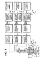
- Figure 2 is a partially schematic, partially diagrammatic illustration of a glass feeder mechanism which feeds gobs of molten glass to and receives positional data from a triple gob, individual section, glass forming machine; and
- Figure 3 is a graph illustrating the final portion of the movement of the mould assembly plunger in forming a parison.
- A glassware forming machine of the individual section, multi-gob type, has a number of individual sections each having a selected number (usually 2, 3 or 4) of parison mould assemblies 10 for simultaneously forming a corresponding number of parisons. Each of these
mold assemblies 10 includes two mold halves 11 which are movable between an advanced position where they engage one another and other parts of the mold assembly to form amold cavity 12 and a retracted position where the mold halves 11 are spaced to permit removal of a formed parison. Aneck ring 14 cooperates with the mold halves 11 to define thecavity 12 and is arranged to grip the neck portion of a formed parison so that the parison can be transferred from the mold cavity to a blow mold. Abaffle 16, movable into a position on top of the engaging mold halves 11, defines the upper surface of the mold cavity and is moved to a remote location prior to parison removal. - Each mold assembly also has a plunger mechanism including a
plunger 20. Theplunger 20 is first moved from its out-of-the-way position to its intermediate position where the plunger projects upwardly into the mold cavity. A gob of molten glass is dropped into themold cavity 12 and rests on theplunger 20. The plunger is then advanced under a variable feed pressure from this intermediate position to press the glass against the walls of thecavity 12 to form the parison. In Figure 1 the plunger is shown during its advancement from the intermediate position to its fully advanced position. The plunger is then retracted to its intermediate position by cutting the feed pressure and applying a retract pressure and then retracted from the intermediate position to the out-of-the-way position to allow for removal of the parison. - The plunger mechanism also has a
cylinder 30, apiston 32 movable in thecylinder 30, and apiston rod 34 projecting from thepiston 32 through aseal 36 in anupper end cap 38 of thecylinder 30. Theplunger 20 is mounted on an upper end portion of thepiston rod 34 by aclamping ring 40. Pressurized hydraulic fluid introduced into thecylinder 30 through anupper entry port 42 causes thepiston 32 to move downwards in thecylinder 30, and the introduction of the fluid throughport 44 causes thepiston 32 to move upwardly in thecylinder 30. - Each parison mold assembly also has a Plunger Displacement Mechanism (a valving arrangement which can alternately apply the feed and retract pressures to the
appropriate cylinder ports 42, 44). The time when each pressure is applied and other control parameters such as duration of application are controlled by a Plunger Controller. - A
feeder bowl 60 containsmolten glass 62 received from a forehearth (not shown). Themolten glass 62 flows below arefractory tube 64 and is discharged throughholes 66 in anorifice plate 68 as runners of molten glass. These runners are simultaneously sheared into discrete gobs by a Shear Mechanism and are delivered by a Gob Distributor to the parison mold assemblies.Needles 70 are individually movable upward and downward by Positioning Mechanisms driven by Positioner Motors to vary the size of the glass stream, and hence, the size of the gobs. Details of conventional, manually operable Positioning Mechanisms for raising or lowering the needles are disclosed in U.S. Patent No. 4,551,163, dated November 5, 1985. - It is within the last 3/8" of plunger pressing stroke, that the mold cavity becomes completely filled in the parison forming process. To track the displacement of each plunger throughout this portion of the stroke, each Parison Mold Assembly includes a Displacement Probe Assembly having a linear potentiometer 50 (Figure 1) secured to the
plunger cylinder 30. As a plunger is displaced through this 3/8", thepiston 32 of that plunger will engage and displace aprobe 52 to which is secured a wiper 54 of the potentiometer. The displacement of this wiper 54 along apotentiometer element 56 changes the output of the linear potentiometer. - Figure 3 illustrates a plot of plunger displacement (voltage), as sensed by the probe, versus time, zero seconds being when the Plunger Controller commences plunger displacement (fires "plunger-up" solenoid, for example). This plot reveals a linear or constant velocity region between points A and B. Since the pressure is constant during this plunger advancement, the force exerted on the glass by the plunger remains constant. It is believed that point A is the point where the mold cavity has completely filled (the parison formation point) and that from point A and B, the glass is cooling, and hence, shrinking. Point B corresponds to the time when the Plunger Controller commences plunger retraction (fires "plunger-down" solenoid, for example).
- The Positioner Motor Controller for each needle receives positional data from its associated Displacement Probe Assembly, determines when Point A has been reached (has determined that the displacement curve has become linear), compares this location to a desired Point A location inputted via thumb wheel switches or the like 72 and drives the Positioner Motor to raise or lower the
associated needle 70 to change the volume of the stream of glass issuing from thehole 66 controlled by theneedle 70 and hence the volume of the gob formed therefrom, to relocate the location of the actual parison formation point of the plunger to the desired Point A location inputted by the operator. Each Positioner Motor Controller may include a digital read out 74 of the actual Point A location. In a semi-automatic system, a thumb wheel switch or the like 76 may be provided for manually inputting needle offsets into the needle Positioner corresponding to the difference between digital read out 72 andthumb wheel switch 74 to relocate the associated needle to the desired Point A location. Such height adjustments to theneedles 70 will maintain a constant parison weight, and will automatically adjust weights between multiple gobs such that all will be of equal value.
Claims (2)
means (32, 34) for displacing each plunger (20) from said retracted to said fully inserted position, said plungers advancing to a parison formation point where the mould cavity has become completely full and then to a fully inserted position as the formed parison cools,
means (50) for sensing the actual position of each of said plungers (20) throughout at least the last portion of its displacement which includes the parison formation point and
means for simultaneously delivering discrete gobs of molten glass to said parison mould assemblies including a feeder bowl (60) having an orifice plate (68) with a corresponding plurality of openings (66), and a corresponding plurality of needles (70) individually displaceable to vary the volume of a stream of glass passing through the corresponding orifice, and shear means for simultaneously shearing a gob from each of the streams, and a Positioner Controller for each plunger, each Positioner Controller comprising
Applications Claiming Priority (2)
| Application Number | Priority Date | Filing Date | Title |
|---|---|---|---|
| US152686 | 1988-02-05 | ||
| US07/152,686 US4816057A (en) | 1988-02-05 | 1988-02-05 | Glass press forming machine |
Publications (2)
| Publication Number | Publication Date |
|---|---|
| EP0327241A1 EP0327241A1 (en) | 1989-08-09 |
| EP0327241B1 true EP0327241B1 (en) | 1992-07-15 |
Family
ID=22543966
Family Applications (1)
| Application Number | Title | Priority Date | Filing Date |
|---|---|---|---|
| EP89300643A Expired EP0327241B1 (en) | 1988-02-05 | 1989-01-24 | Glass forming machine |
Country Status (4)
| Country | Link |
|---|---|
| US (1) | US4816057A (en) |
| EP (1) | EP0327241B1 (en) |
| JP (1) | JP2701914B2 (en) |
| DE (1) | DE68902061T2 (en) |
Families Citing this family (6)
| Publication number | Priority date | Publication date | Assignee | Title |
|---|---|---|---|---|
| JP2541873B2 (en) * | 1990-11-28 | 1996-10-09 | 石塚硝子株式会社 | Glass bottle molding machine |
| DE10254654A1 (en) * | 2002-11-22 | 2004-06-09 | Heinz-Glas Gmbh | Device and method for processing glass items of different masses and feeding device |
| US10618831B2 (en) | 2018-01-10 | 2020-04-14 | Owens-Brockway Glass Container Inc. | Parison plunger actuation |
| EP3915949B1 (en) * | 2020-05-29 | 2024-07-03 | Emhart Glass S.A. | Glass forming machine with individually controlled plunger end positions |
| ES2969576T3 (en) | 2021-08-05 | 2024-05-21 | Emhart Glass Sa | Glass forming machine comprising a cleaning device and method |
| US20250019288A1 (en) * | 2021-11-23 | 2025-01-16 | Corning Incorporated | Mold release coatings for glass forming or processing equipment and related methods |
Family Cites Families (6)
| Publication number | Priority date | Publication date | Assignee | Title |
|---|---|---|---|---|
| US1532254A (en) * | 1921-11-21 | 1925-04-07 | William J Miller | Process and apparatus for controlling the feeding of glass |
| US3192027A (en) * | 1961-07-03 | 1965-06-29 | Owens Illinois Glass Co | Apparatus for measuring plunger penetration in glass forming machines |
| DE3151521C2 (en) * | 1981-12-24 | 1984-04-26 | Veba-Glas Ag, 4300 Essen | Method and apparatus for measuring the position of a ram of a glassware molding machine |
| DE3401465C1 (en) * | 1984-01-18 | 1985-01-31 | Fa. Hermann Heye, 3063 Obernkirchen | Transducer for the position verification of a press stamp |
| US4551163A (en) * | 1984-06-04 | 1985-11-05 | Emhart Industries, Inc. | Electronic glass feeder plunger operating mechanism |
| GB2159813B (en) * | 1984-06-06 | 1987-12-31 | Emhart Ind | Forming a gob of molten glass into a parison |
-
1988
- 1988-02-05 US US07/152,686 patent/US4816057A/en not_active Expired - Lifetime
-
1989
- 1989-01-24 EP EP89300643A patent/EP0327241B1/en not_active Expired
- 1989-01-24 DE DE8989300643T patent/DE68902061T2/en not_active Expired - Lifetime
- 1989-02-03 JP JP1025620A patent/JP2701914B2/en not_active Expired - Lifetime
Also Published As
| Publication number | Publication date |
|---|---|
| EP0327241A1 (en) | 1989-08-09 |
| US4816057A (en) | 1989-03-28 |
| DE68902061T2 (en) | 1992-12-03 |
| JPH01242425A (en) | 1989-09-27 |
| DE68902061D1 (en) | 1992-08-20 |
| JP2701914B2 (en) | 1998-01-21 |
Similar Documents
| Publication | Publication Date | Title |
|---|---|---|
| CA1266979A (en) | Forming a gob of molten glass into a parison | |
| EP1426160B1 (en) | Hot runner co-injection nozzle | |
| CZ293829B6 (en) | Method of forming a gob of molten glass into a hollow article and apparatus for making the same | |
| US4867778A (en) | Individual section glass forming machine | |
| US5236485A (en) | Process and device for shaping a gob | |
| US4816057A (en) | Glass press forming machine | |
| CZ570187A3 (en) | Process of luminescent screen moulding and apparatus for making the same | |
| US4052187A (en) | Apparatus for producing glass parison by the press-and-blow process | |
| EP1129039B1 (en) | Method and device for pressing a gob | |
| JPS6353013B2 (en) | ||
| US4518409A (en) | Method of and apparatus for making a parison | |
| US4786306A (en) | Individual section glass forming machine | |
| EP1765561B1 (en) | Apparatuses for producing objects | |
| JP2594447B2 (en) | Method and apparatus for forming a glass block | |
| EP1565410B1 (en) | Installation for the production of glass stoppers used for sealing bottles | |
| US3434821A (en) | Apparatus for pressing articles of thermoplastic material | |
| US20060213226A1 (en) | Method and device for regulating the glass gob mass during the production of hollow glass containers | |
| DE3025333A1 (en) | Punch for making parisons in glass moulding machine - where punch is located on hydraulic cylinder, which is reciprocated in rigid guide sleeve to provide accurate punch stroke | |
| WO1999014166A1 (en) | Apparatus for handling molten glass | |
| US3446611A (en) | Apparatus for centrifugally casting glass articles | |
| US3413108A (en) | Glass forming machine having molds with movable bottom sections | |
| JPS5920606B2 (en) | glass product forming machine | |
| EP3915949B1 (en) | Glass forming machine with individually controlled plunger end positions | |
| JPH0679758B2 (en) | Casting machine | |
| JPS60187514A (en) | Parison thickness adjuster |
Legal Events
| Date | Code | Title | Description |
|---|---|---|---|
| PUAI | Public reference made under article 153(3) epc to a published international application that has entered the european phase |
Free format text: ORIGINAL CODE: 0009012 |
|
| AK | Designated contracting states |
Kind code of ref document: A1 Designated state(s): DE FR GB IT |
|
| RAP1 | Party data changed (applicant data changed or rights of an application transferred) |
Owner name: EMHART INDUSTRIES, INC. |
|
| 17P | Request for examination filed |
Effective date: 19900111 |
|
| 17Q | First examination report despatched |
Effective date: 19910313 |
|
| RAP1 | Party data changed (applicant data changed or rights of an application transferred) |
Owner name: EMHART GLASS MACHINERY INC., |
|
| RAP1 | Party data changed (applicant data changed or rights of an application transferred) |
Owner name: EMHART GLASS MACHINERY INVESTMENTS INC. |
|
| GRAA | (expected) grant |
Free format text: ORIGINAL CODE: 0009210 |
|
| AK | Designated contracting states |
Kind code of ref document: B1 Designated state(s): DE FR GB IT |
|
| REF | Corresponds to: |
Ref document number: 68902061 Country of ref document: DE Date of ref document: 19920820 |
|
| ET | Fr: translation filed | ||
| PLBI | Opposition filed |
Free format text: ORIGINAL CODE: 0009260 |
|
| ITF | It: translation for a ep patent filed | ||
| 26 | Opposition filed |
Opponent name: HERRMANN HEYE Effective date: 19920909 |
|
| PLBN | Opposition rejected |
Free format text: ORIGINAL CODE: 0009273 |
|
| STAA | Information on the status of an ep patent application or granted ep patent |
Free format text: STATUS: OPPOSITION REJECTED |
|
| 27O | Opposition rejected |
Effective date: 19940523 |
|
| REG | Reference to a national code |
Ref country code: FR Ref legal event code: TP |
|
| REG | Reference to a national code |
Ref country code: GB Ref legal event code: IF02 |
|
| PGFP | Annual fee paid to national office [announced via postgrant information from national office to epo] |
Ref country code: IT Payment date: 20080129 Year of fee payment: 20 Ref country code: GB Payment date: 20080129 Year of fee payment: 20 |
|
| PGFP | Annual fee paid to national office [announced via postgrant information from national office to epo] |
Ref country code: DE Payment date: 20080229 Year of fee payment: 20 Ref country code: FR Payment date: 20080117 Year of fee payment: 20 |
|
| REG | Reference to a national code |
Ref country code: GB Ref legal event code: PE20 Expiry date: 20090123 |
|
| PG25 | Lapsed in a contracting state [announced via postgrant information from national office to epo] |
Ref country code: GB Free format text: LAPSE BECAUSE OF EXPIRATION OF PROTECTION Effective date: 20090123 |