EP0327012B1 - Variable speed pressure energy translating device with an arcuate reinforced polymer bearing - Google Patents
Variable speed pressure energy translating device with an arcuate reinforced polymer bearing Download PDFInfo
- Publication number
- EP0327012B1 EP0327012B1 EP89101613A EP89101613A EP0327012B1 EP 0327012 B1 EP0327012 B1 EP 0327012B1 EP 89101613 A EP89101613 A EP 89101613A EP 89101613 A EP89101613 A EP 89101613A EP 0327012 B1 EP0327012 B1 EP 0327012B1
- Authority
- EP
- European Patent Office
- Prior art keywords
- set forth
- openings
- device set
- perforations
- bearing
- Prior art date
- Legal status (The legal status is an assumption and is not a legal conclusion. Google has not performed a legal analysis and makes no representation as to the accuracy of the status listed.)
- Expired - Lifetime
Links
Images


Classifications
-
- F—MECHANICAL ENGINEERING; LIGHTING; HEATING; WEAPONS; BLASTING
- F16—ENGINEERING ELEMENTS AND UNITS; GENERAL MEASURES FOR PRODUCING AND MAINTAINING EFFECTIVE FUNCTIONING OF MACHINES OR INSTALLATIONS; THERMAL INSULATION IN GENERAL
- F16C—SHAFTS; FLEXIBLE SHAFTS; ELEMENTS OR CRANKSHAFT MECHANISMS; ROTARY BODIES OTHER THAN GEARING ELEMENTS; BEARINGS
- F16C17/00—Sliding-contact bearings for exclusively rotary movement
- F16C17/02—Sliding-contact bearings for exclusively rotary movement for radial load only
-
- F—MECHANICAL ENGINEERING; LIGHTING; HEATING; WEAPONS; BLASTING
- F04—POSITIVE - DISPLACEMENT MACHINES FOR LIQUIDS; PUMPS FOR LIQUIDS OR ELASTIC FLUIDS
- F04B—POSITIVE-DISPLACEMENT MACHINES FOR LIQUIDS; PUMPS
- F04B1/00—Multi-cylinder machines or pumps characterised by number or arrangement of cylinders
- F04B1/12—Multi-cylinder machines or pumps characterised by number or arrangement of cylinders having cylinder axes coaxial with, or parallel or inclined to, main shaft axis
- F04B1/20—Multi-cylinder machines or pumps characterised by number or arrangement of cylinders having cylinder axes coaxial with, or parallel or inclined to, main shaft axis having rotary cylinder block
- F04B1/2014—Details or component parts
- F04B1/2078—Swash plates
- F04B1/2085—Bearings for swash plates or driving axles
-
- F—MECHANICAL ENGINEERING; LIGHTING; HEATING; WEAPONS; BLASTING
- F16—ENGINEERING ELEMENTS AND UNITS; GENERAL MEASURES FOR PRODUCING AND MAINTAINING EFFECTIVE FUNCTIONING OF MACHINES OR INSTALLATIONS; THERMAL INSULATION IN GENERAL
- F16C—SHAFTS; FLEXIBLE SHAFTS; ELEMENTS OR CRANKSHAFT MECHANISMS; ROTARY BODIES OTHER THAN GEARING ELEMENTS; BEARINGS
- F16C33/00—Parts of bearings; Special methods for making bearings or parts thereof
- F16C33/02—Parts of sliding-contact bearings
- F16C33/04—Brasses; Bushes; Linings
- F16C33/20—Sliding surface consisting mainly of plastics
-
- F—MECHANICAL ENGINEERING; LIGHTING; HEATING; WEAPONS; BLASTING
- F05—INDEXING SCHEMES RELATING TO ENGINES OR PUMPS IN VARIOUS SUBCLASSES OF CLASSES F01-F04
- F05C—INDEXING SCHEME RELATING TO MATERIALS, MATERIAL PROPERTIES OR MATERIAL CHARACTERISTICS FOR MACHINES, ENGINES OR PUMPS OTHER THAN NON-POSITIVE-DISPLACEMENT MACHINES OR ENGINES
- F05C2253/00—Other material characteristics; Treatment of material
- F05C2253/12—Coating
-
- F—MECHANICAL ENGINEERING; LIGHTING; HEATING; WEAPONS; BLASTING
- F16—ENGINEERING ELEMENTS AND UNITS; GENERAL MEASURES FOR PRODUCING AND MAINTAINING EFFECTIVE FUNCTIONING OF MACHINES OR INSTALLATIONS; THERMAL INSULATION IN GENERAL
- F16C—SHAFTS; FLEXIBLE SHAFTS; ELEMENTS OR CRANKSHAFT MECHANISMS; ROTARY BODIES OTHER THAN GEARING ELEMENTS; BEARINGS
- F16C2208/00—Plastics; Synthetic resins, e.g. rubbers
- F16C2208/20—Thermoplastic resins
- F16C2208/30—Fluoropolymers
- F16C2208/32—Polytetrafluorethylene [PTFE]
-
- F—MECHANICAL ENGINEERING; LIGHTING; HEATING; WEAPONS; BLASTING
- F16—ENGINEERING ELEMENTS AND UNITS; GENERAL MEASURES FOR PRODUCING AND MAINTAINING EFFECTIVE FUNCTIONING OF MACHINES OR INSTALLATIONS; THERMAL INSULATION IN GENERAL
- F16C—SHAFTS; FLEXIBLE SHAFTS; ELEMENTS OR CRANKSHAFT MECHANISMS; ROTARY BODIES OTHER THAN GEARING ELEMENTS; BEARINGS
- F16C2220/00—Shaping
- F16C2220/20—Shaping by sintering pulverised material, e.g. powder metallurgy
-
- F—MECHANICAL ENGINEERING; LIGHTING; HEATING; WEAPONS; BLASTING
- F16—ENGINEERING ELEMENTS AND UNITS; GENERAL MEASURES FOR PRODUCING AND MAINTAINING EFFECTIVE FUNCTIONING OF MACHINES OR INSTALLATIONS; THERMAL INSULATION IN GENERAL
- F16C—SHAFTS; FLEXIBLE SHAFTS; ELEMENTS OR CRANKSHAFT MECHANISMS; ROTARY BODIES OTHER THAN GEARING ELEMENTS; BEARINGS
- F16C2220/00—Shaping
- F16C2220/80—Shaping by separating parts, e.g. by severing, cracking
- F16C2220/84—Shaping by separating parts, e.g. by severing, cracking by perforating; by punching; by stamping-out
-
- F—MECHANICAL ENGINEERING; LIGHTING; HEATING; WEAPONS; BLASTING
- F16—ENGINEERING ELEMENTS AND UNITS; GENERAL MEASURES FOR PRODUCING AND MAINTAINING EFFECTIVE FUNCTIONING OF MACHINES OR INSTALLATIONS; THERMAL INSULATION IN GENERAL
- F16C—SHAFTS; FLEXIBLE SHAFTS; ELEMENTS OR CRANKSHAFT MECHANISMS; ROTARY BODIES OTHER THAN GEARING ELEMENTS; BEARINGS
- F16C2240/00—Specified values or numerical ranges of parameters; Relations between them
- F16C2240/40—Linear dimensions, e.g. length, radius, thickness, gap
- F16C2240/60—Thickness, e.g. thickness of coatings
-
- F—MECHANICAL ENGINEERING; LIGHTING; HEATING; WEAPONS; BLASTING
- F16—ENGINEERING ELEMENTS AND UNITS; GENERAL MEASURES FOR PRODUCING AND MAINTAINING EFFECTIVE FUNCTIONING OF MACHINES OR INSTALLATIONS; THERMAL INSULATION IN GENERAL
- F16C—SHAFTS; FLEXIBLE SHAFTS; ELEMENTS OR CRANKSHAFT MECHANISMS; ROTARY BODIES OTHER THAN GEARING ELEMENTS; BEARINGS
- F16C2240/00—Specified values or numerical ranges of parameters; Relations between them
- F16C2240/40—Linear dimensions, e.g. length, radius, thickness, gap
- F16C2240/70—Diameters; Radii
-
- F—MECHANICAL ENGINEERING; LIGHTING; HEATING; WEAPONS; BLASTING
- F16—ENGINEERING ELEMENTS AND UNITS; GENERAL MEASURES FOR PRODUCING AND MAINTAINING EFFECTIVE FUNCTIONING OF MACHINES OR INSTALLATIONS; THERMAL INSULATION IN GENERAL
- F16C—SHAFTS; FLEXIBLE SHAFTS; ELEMENTS OR CRANKSHAFT MECHANISMS; ROTARY BODIES OTHER THAN GEARING ELEMENTS; BEARINGS
- F16C2360/00—Engines or pumps
Definitions
- the invention relates to a variable speed pressure energy translating device according to the preamble of claim 1.
- a variable speed pressure energy translating device is e.g. known from US-A-3 991 658.
- Hydraulic pumps and motors of the piston type utilize a plurality of axially extending pistons and associated cylinders and a yoke engaged by the pistons and pivoted by annular bearings in a housing.
- the bearing form is that of a partial journal bearing often termed a "saddle bearing".
- the use of this bearing form gives the advantage of a reduction in overall size and in utilizing fewer parts in the bearing area thereby making it more reliable, easier to maintain, involving less deflection on the yoke.
- the saddle bearing can be either a rolling element or a non-rolling element bearing format. This invention deals with a non-rolling element form of saddle bearing.
- journal bearings In hydraulic pumps and motors journal bearings generally function through hydrodynamic, hydrostatic or hybrid oil film generation processes. There are, however, circumstances when normal lubrication mechanics are insufficient to correctly form a fluid film for the journal bearing to function, typical cases are extreme load, quasi-steady state operation or poor lubrication. Such is the case with a non hydrostatic form of a saddle bearing. Under these circumstances surface to surface contact can and does occur with resulting high coefficients of friction and wear rates. In an attempt to overcome this problem a self lubricated material is used for one of the surfaces in contact. Self lubricated bearings, thus formed however, do have limitations; temperature, load, speed of operation, etc. Many of the self lubricated bearing forms utilize a polymer as the self lubricated material.
- a bearing material is known (DE-A 3 304 141) comprising a layer of polymeric material and a reinforcing member embedded in the polymeric material and having a plurality of openings or perforations through which that polymeric material extends, filling out such openings or perforations. Furthermore, the cross section of such opening or perforations varies to create a good adherence between metal body and polymeric material.
- a further bearing material covering sheet is known (DE-C-2 205 008) consisting of woven metal wires and fluoropolymer material where the wires are thermally bonded together.
- the problem to be solved by invention is to provide a variable speed pressure energy translating device of the type referred to above which has a non-rolling element saddle type bearing of increased load capacity, which would withstand the normal forces on the bearing and which can be relatively easily manufactured.
- the invention relates particularly to a pressure energy translating device in the form of a pump or motor that is of generally well known construction and comprises a housing 20 with a housing cover 21.
- a drive shaft 22 is mounted in the pump housing and cover and supports a rotor 23 which houses an annular series of pump cylinders 24, each of which incorporates an axially movable pump piston 25.
- Each pump cylinder 24 has an opening 26 and these openings function, as the rotor turns, in a manner like that of a slide valve with the pump housing cover 21.
- the pistons 25 in the cylinders 24 work in unison with an obliquely set yoke 27 in such a manner that as the rotor revolves, the pistons produce an axial back-and-forth motion.
- the yoke 27 has arcuate bearing surfaces of seats 28 that are engaged by arcuate saddle bearings 30 mounted in recesses 31 in the housing 20.
- a spring 33 yieldingly urges the yoke 27 to an oblique position, as shown, when under no pressure.
- the yoke 27 can be moved under pressure from a piston 34 to vary the pump displacement. Pressure regulators and other controls are provided in the head 21 as is well known in the art.
- the bearing 30 comprises an arcuate body of thermoplastic material, preferably polytetrafluoroethylene, and an arcuate reinforcing member at least partially embedded in the plastic body.
- a preferred form of bearing comprises the plastic body 35, an arcuate metal shim 36 having openings 37 through which a portion of the plastic extends, and an arcuate metal backing member 38 adhered to the shim and plastic by adhesive 39.
- the bearing is made initially in flat form.
- the three piece bearing can be formed into one unit by the application of pressure in a heat box.
- the plastic 35 is formed through the openings 37 and the metal member 36 is adhered to the backing member 38.
- the bearing is formed to the required shape.
- the body 35 and metal member 36 may be formed and shaped prior to applying to the previously curved backing member 38.
- the thickness of the thin member 36 is 0.381 mm
- the assembled thickness of the bearing is 3.00 mm
- the thickness of the backing member 38 is 1.9 mm.
- the openings in the thin member 36 have a diameter of 1.00 mm and are provided in rows spaced apart 2.00 mm.
- the openings 37 in metal member 38 are preferably formed such that they are not of the same cross section in order to increase the shear strength. More specifically, if the openings 37 are photochemically etched, they have an hourglass shape, as shown in Fig. 16, including a narrow intermediate portion 37a, and flared end portions 37b, 37c which serve to more effectively lock the plastic body 35 and metal member 36. This increases the shear strength. If the openings 37 are formed by punching, the punching operation results in a narrow portion 37d, a sharp edge 37e at one end and a flared portion 37f at the other end. This also serves to increase the shear strength.
- the bearing comprises an embedded member 36a in the form of a specially fabricated metal wire mesh which has interwoven wires 40, 41 and openings therebetween.
- the wires 40, 41 are flattened as at 42 by passing through rollers and are sintered to one another so that the wires 40, 41 are bonded and fixed relative to one another prior to embedding in the body 35a, 35b, body part 35b forming a layer of polymeric material.
- the bearing can be utilized with or without a backing member 38 (Fig. 10) adherent to the layer 35b.
- the body is first fabricated in flat form and then rolled and curved to the desired arcuate configuration as shown in Fig. 13.
- the backing member 38 comprises a rather coarse screen having wires 45 and openings 46.
- the wires 45 are flattened and sintered to one another and to the wire mesh 40, 41 as by sintering.
- the bearing obtained is compliant.
- a backing plate 38c also has openings 46 through which the plastic of the body extends to form a compliant bearing which will accommodate tolerances in the outer surfaces of layers 35a and 38b.
- the effective yield strength of the plastic polymer is increased by utilization of an embedded thin member which has the effect of minimizing the yielding under load by mechanically locking the polymer in place.
- the welding or bonding of the strands together with the flattening of the strands increases the mechanical bonding and prevents the strands from sliding relative to one another.
Landscapes
- Engineering & Computer Science (AREA)
- General Engineering & Computer Science (AREA)
- Mechanical Engineering (AREA)
- Reciprocating Pumps (AREA)
- Details Of Reciprocating Pumps (AREA)
- Hydraulic Motors (AREA)
- Sliding-Contact Bearings (AREA)
- Shafts, Cranks, Connecting Bars, And Related Bearings (AREA)
- Control Of Fluid Gearings (AREA)
- Structures Of Non-Positive Displacement Pumps (AREA)
Description
- The invention relates to a variable speed pressure energy translating device according to the preamble of claim 1. Such a device is e.g. known from US-A-3 991 658.
- Hydraulic pumps and motors of the piston type utilize a plurality of axially extending pistons and associated cylinders and a yoke engaged by the pistons and pivoted by annular bearings in a housing.
- In another type of hydraulic pump or motor, the bearing form is that of a partial journal bearing often termed a "saddle bearing". The use of this bearing form gives the advantage of a reduction in overall size and in utilizing fewer parts in the bearing area thereby making it more reliable, easier to maintain, involving less deflection on the yoke. The saddle bearing can be either a rolling element or a non-rolling element bearing format. This invention deals with a non-rolling element form of saddle bearing.
- In hydraulic pumps and motors journal bearings generally function through hydrodynamic, hydrostatic or hybrid oil film generation processes. There are, however, circumstances when normal lubrication mechanics are insufficient to correctly form a fluid film for the journal bearing to function, typical cases are extreme load, quasi-steady state operation or poor lubrication. Such is the case with a non hydrostatic form of a saddle bearing. Under these circumstances surface to surface contact can and does occur with resulting high coefficients of friction and wear rates. In an attempt to overcome this problem a self lubricated material is used for one of the surfaces in contact. Self lubricated bearings, thus formed however, do have limitations; temperature, load, speed of operation, etc. Many of the self lubricated bearing forms utilize a polymer as the self lubricated material. While these polymers impart a low coefficient of friction for the bearing pair they have a relatively low load capacity due to the yield strength of the polymer. Other materials possessing a higher yield strength cannot achieve a suitably low coefficient of friction. Attempts have been made to increase the yield strength of the polymer by the use of a filler material intimately mixed with the polymer to form a composite material. These composites have, however, failed due to an increase in the coefficients of friction. These higher coefficients of friction are due to the wear process exposing the filler material so that the mating surface no longer rides on a true polymer interface. Another technique, which has been used to attempt to increase the yield strength of the polymer is the incorporation of a woven metal screen to form a composite. This also fails as the friction between the metal threads is insufficient to prevent yielding of both the polymer and the lateral movement of the screen wires across each other. Further, the yielding of the screen wire can be preferential depending on the direction of the shear force and the "lay" or "bias" of the woven screen. Attempts to further increase the strength of the composite by adhesively bonding the screen to a metal backing has failed as the area open to bonding is small due to the roundness of the screen wires and the fill of the polymer in the mesh.
- A bearing material is known (DE-A 3 304 141) comprising a layer of polymeric material and a reinforcing member embedded in the polymeric material and having a plurality of openings or perforations through which that polymeric material extends, filling out such openings or perforations. Furthermore, the cross section of such opening or perforations varies to create a good adherence between metal body and polymeric material.
- A further bearing material covering sheet is known (DE-C-2 205 008) consisting of woven metal wires and fluoropolymer material where the wires are thermally bonded together.
- The problem to be solved by invention is to provide a variable speed pressure energy translating device of the type referred to above which has a non-rolling element saddle type bearing of increased load capacity, which would withstand the normal forces on the bearing and which can be relatively easily manufactured.
- The solution to this problem can be found in claim 1;
further developments are characterized in the further claims. - Embodiments of the invention are shown in the drawings in which:
- Fig. 1 is a longitudinal part sectional view of a positive displacement pump or motor embodying the invention.
- Fig. 2 is a sectional view taken along the line 2-2 in Fig. 1, parts taking taken away.
- Fig. 3 is a sectional view similar to Fig. 1, parts being taken away.
- Fig. 4 is a plan view of the yoke of the pump or motor.
- Fig. 5 is a plan view of the bearing.
- Fig. 6 is a side view of the bearing.
- Fig. 7 is a fragmentary sectional view on a greatly enlarged scale taken along the line 7-7 in Fig. 6.
- Fig. 8 is a plan view of a portion of the bearing.
- Fig. 9 is an exploded view of the parts of the bearing prior to their being assembled.
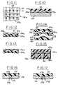
- Fig. 10 is a fragmentary sectional view of a modified form of bearing.
- Fig. 11 is a fragmentary plan view on an enlarged scale of a portion of the bearing shown in Fig. 12.
- Fig. 12 is a fragmentary sectional view on enlarged scale of another portion of the bearing shown in Fig. 10.
- Fig. 13 is a fragmentary sectional view showing the bearing portion of Fig. 12 after it is formed to arcuate form.
- Fig. 14 is a further modified form of bearing.
- Fig. 15 is another form of the bearing.
- Fig. 16 is a fragmentary sectional view on an enlarged scale of a portion of the bearing shown in Fig. 7.
- Fig. 17 is a fragmentary sectional view on an enlarged scale of a modified form of bearing.
- Referring to Figs. 1-4, the invention relates particularly to a pressure energy translating device in the form of a pump or motor that is of generally well known construction and comprises a
housing 20 with ahousing cover 21. Adrive shaft 22 is mounted in the pump housing and cover and supports arotor 23 which houses an annular series ofpump cylinders 24, each of which incorporates an axiallymovable pump piston 25. Eachpump cylinder 24 has anopening 26 and these openings function, as the rotor turns, in a manner like that of a slide valve with thepump housing cover 21. Thepistons 25 in thecylinders 24 work in unison with an obliquelyset yoke 27 in such a manner that as the rotor revolves, the pistons produce an axial back-and-forth motion. Theyoke 27 has arcuate bearing surfaces ofseats 28 that are engaged byarcuate saddle bearings 30 mounted inrecesses 31 in thehousing 20. Aspring 33 yieldingly urges theyoke 27 to an oblique position, as shown, when under no pressure. Theyoke 27 can be moved under pressure from apiston 34 to vary the pump displacement. Pressure regulators and other controls are provided in thehead 21 as is well known in the art. - In accordance with the invention, the
bearing 30 comprises an arcuate body of thermoplastic material, preferably polytetrafluoroethylene, and an arcuate reinforcing member at least partially embedded in the plastic body. - Referring to Figs. 5-9, a preferred form of bearing comprises the
plastic body 35, anarcuate metal shim 36 havingopenings 37 through which a portion of the plastic extends, and an arcuatemetal backing member 38 adhered to the shim and plastic byadhesive 39. - The bearing is made initially in flat form. By using a film form of adhesive that is cured by heat and pressure, the three piece bearing can be formed into one unit by the application of pressure in a heat box. In this process, the
plastic 35 is formed through theopenings 37 and themetal member 36 is adhered to thebacking member 38. After curing, the bearing is formed to the required shape. Alternatively, thebody 35 andmetal member 36 may be formed and shaped prior to applying to the previouslycurved backing member 38. In a typical example, the thickness of thethin member 36 is 0.381 mm, the assembled thickness of the bearing is 3.00 mm and the thickness of thebacking member 38 is 1.9 mm. The openings in thethin member 36 have a diameter of 1.00 mm and are provided in rows spaced apart 2.00 mm. - The
openings 37 inmetal member 38 are preferably formed such that they are not of the same cross section in order to increase the shear strength. More specifically, if theopenings 37 are photochemically etched, they have an hourglass shape, as shown in Fig. 16, including a narrowintermediate portion 37a, and flared end portions 37b, 37c which serve to more effectively lock theplastic body 35 andmetal member 36. This increases the shear strength. If theopenings 37 are formed by punching, the punching operation results in anarrow portion 37d, a sharp edge 37e at one end and a flaredportion 37f at the other end. This also serves to increase the shear strength. - In the form shown in Figs. 10-13 the bearing comprises an embedded
member 36a in the form of a specially fabricated metal wire mesh which has interwovenwires wires wires body body part 35b forming a layer of polymeric material. The bearing can be utilized with or without a backing member 38 (Fig. 10) adherent to thelayer 35b. As shown in Fig. 12, the body is first fabricated in flat form and then rolled and curved to the desired arcuate configuration as shown in Fig. 13. - In the form shown in Fig. 14, the backing
member 38 comprises a rather coarsescreen having wires 45 andopenings 46. Thewires 45 are flattened and sintered to one another and to thewire mesh - In the form shown in Fig. 15, a
backing plate 38c also hasopenings 46 through which the plastic of the body extends to form a compliant bearing which will accommodate tolerances in the outer surfaces oflayers 35a and 38b. - It can thus be seen that in each of the forms of the invention, the effective yield strength of the plastic polymer is increased by utilization of an embedded thin member which has the effect of minimizing the yielding under load by mechanically locking the polymer in place.
- In the form where the embedded member comprises woven metal screening, the welding or bonding of the strands together with the flattening of the strands increases the mechanical bonding and prevents the strands from sliding relative to one another.
Claims (15)
- A variable speed pressure energy translating device which includes a plurality of axially extending pistons (25) and associated cylinders (24) and a yoke (27) engaged by the pistons (25) and pivoted on a transverse axis for varying the displacement of the pump or motor, comprising
a housing (20) having spaced saddle bearing seats (31), said yoke (27) having spaced complementary saddle bearing engaging portions (28),
and an arcuate bearing (30) comprising an arcuate body (35) of polymeric material seated in each of said seats (31),
characterized in that
each said bearing (30) comprises an arcuate reinforcing member (36) embedded in said body and has a plurality of openings (43) or perforations (37) extending therethrough, said openings or perforations (37) have a cross section which varies longitudinally thereof, and said polymeric material filling and extending throughout said openings (43) or perforations (37). - The device set forth in claim 1,
wherein said polymeric material extends entirely through said openings (43) or perforations (37) and forms a layer (35b, 38b) of polymeric material adjacent to said seat (31). - The device set forth in claim 1 or 2
wherein said reinforcing member comprises a thin metal sheet (36) having said perforations (37) therein, said perforations (37) being arranged in rows through said thin metal sheet (36). - The device set forth in any of claims 1 to 3,
wherein said openings or perforations are photochemically etched. - The device set forth in any of claims 1 to 3,
wherein said openings or perforations are made by punching. - The device set forth in any of claims 3 to 5,
wherein said openings or perforations (37d) include at least an outwardly flared end (37f). - The device set forth in any of claims 1 to 6,
including a metal backing member (38) interposed between said seats (31) and said reinforcing member (36) and adhered to said metal reinforcing member (36). - The device set forth in claim 1 or 2,
wherein said reinforcing member (36) comprises a woven metal body (36a) defining said openings (43), said woven body (36a) comprising strands (40, 41) which are interlineated, said strands being flattened at the overlapping portions (42) and directly bonded to one another at said overlapping portions. - The device set forth in any of claims 1 to 8,
wherein said reinforcing member (36) is provided adjacent one surface of said polymeric body. - The device set forth in any of claims 1 to 9,
wherein said bearing comprises a metal body (38) interposed between said seat (31) and said arcuate body (35) and adhered to said arcuate body (35). - The device set forth in claim 8 or 9,
including a second reinforcing member comprising a woven body (45) defining openings (46), said second woven body (45) comprising strands which are interlineated, said strands of said second woven body (45) being flattened at the overlapping portions and directly bonded to one another at said overlapping portions. - The device set forth in claim 11,
wherein said polymeric material extends entirely through said openings (46) and forms a layer (38b) of polymeric material adjacent said seat (31). - The device set forth in claim 11 or 12,
wherein said second woven body (45) is directly bonded to said first woven body (36a). - The device set forth in claim 13,
including a reinforcing member comprising a thin metal sheet (38c) having openings (46) therein embedded in said body. - The device set forth in claim 14,
wherein said polymeric material extends entirely through said openings or perforations and forms a layer (38b) of polymeric material adjacent said seat (31).
Applications Claiming Priority (2)
| Application Number | Priority Date | Filing Date | Title |
|---|---|---|---|
| US150933 | 1988-02-01 | ||
| US07/150,933 US4862789A (en) | 1988-02-01 | 1988-02-01 | Positive displacement pump or motor utilizing a self-lubricated bearing |
Publications (3)
| Publication Number | Publication Date |
|---|---|
| EP0327012A2 EP0327012A2 (en) | 1989-08-09 |
| EP0327012A3 EP0327012A3 (en) | 1990-06-27 |
| EP0327012B1 true EP0327012B1 (en) | 1994-06-29 |
Family
ID=22536612
Family Applications (1)
| Application Number | Title | Priority Date | Filing Date |
|---|---|---|---|
| EP89101613A Expired - Lifetime EP0327012B1 (en) | 1988-02-01 | 1989-01-31 | Variable speed pressure energy translating device with an arcuate reinforced polymer bearing |
Country Status (8)
| Country | Link |
|---|---|
| US (1) | US4862789A (en) |
| EP (1) | EP0327012B1 (en) |
| JP (2) | JPH029953A (en) |
| CN (1) | CN1017367B (en) |
| AU (1) | AU619243B2 (en) |
| CA (1) | CA1327915C (en) |
| DE (1) | DE68916445T2 (en) |
| ES (1) | ES2056128T3 (en) |
Families Citing this family (17)
| Publication number | Priority date | Publication date | Assignee | Title |
|---|---|---|---|---|
| US5017095A (en) * | 1988-02-01 | 1991-05-21 | Vickers, Incorporated | Power transmission |
| JP2624015B2 (en) * | 1990-05-21 | 1997-06-25 | 株式会社日立製作所 | Constant velocity joint and axial piston pump / motor device using the joint |
| US5094590A (en) * | 1990-10-09 | 1992-03-10 | General Motors Corporation | Variable displacement compressor with shaft end play compensation |
| US5229198A (en) * | 1992-05-18 | 1993-07-20 | Pacific Bearing Co. | Bearing material having a matrix impregnated with polymeric resin |
| DE4303177A1 (en) * | 1993-02-04 | 1994-08-11 | Freudenberg Carl Fa | Guide sleeve |
| WO1995001903A1 (en) * | 1993-07-07 | 1995-01-19 | Macor Marine Systems International Gmbh | Slide bearing, in particular for hatchway covers on board of ships |
| US5434178A (en) * | 1993-11-30 | 1995-07-18 | G.D. Searle & Co. | 1,3,5 trisubstituted pyrazole compounds for treatment of inflammation |
| US5630352A (en) * | 1996-03-08 | 1997-05-20 | Vickers, Incorporated | Variable displacement hydrualic piston machine saddle bearing |
| US5730042A (en) * | 1996-12-04 | 1998-03-24 | Caterpillar Inc. | Retaining device for axial piston machines |
| US6209825B1 (en) | 1998-02-27 | 2001-04-03 | Lockheed Martin Corporation | Low power loss electro hydraulic actuator |
| DE19816926C2 (en) | 1998-04-16 | 2000-03-23 | Brueninghaus Hydromatik Gmbh | Axial piston machine with a swash plate pivotally mounted in a swivel bearing |
| JP2003278742A (en) * | 2002-03-26 | 2003-10-02 | Daido Metal Co Ltd | Both surface sliding thrust bearing |
| CN100394047C (en) * | 2002-10-14 | 2008-06-11 | 圣戈班性能塑料帕姆普斯有限公司 | Plain bearing material |
| CN1302207C (en) * | 2004-04-06 | 2007-02-28 | 胡世璇 | Hydraulic motor using self-lubricating composite material as friction assistant |
| CN100385125C (en) * | 2005-01-10 | 2008-04-30 | 胡世璇 | High Precision Hydraulic Synchronous Proportional Divider-Collector |
| FR2988142B1 (en) * | 2012-03-14 | 2014-04-18 | Peugeot Citroen Automobiles Sa | HYDRAULIC MACHINE WITH VARIABLE CYLINDER, IN PARTICULAR FOR A MOTOR VEHICLE |
| US10428874B2 (en) * | 2014-12-19 | 2019-10-01 | Saint-Gobain Performance Plastics Pampus Gmbh | Sliding component and method of forming the same |
Citations (1)
| Publication number | Priority date | Publication date | Assignee | Title |
|---|---|---|---|---|
| US3991658A (en) * | 1972-06-20 | 1976-11-16 | Bobier Wilfred S | Fluid device having sintered metal components |
Family Cites Families (17)
| Publication number | Priority date | Publication date | Assignee | Title |
|---|---|---|---|---|
| US3124008A (en) * | 1964-03-10 | firth etal | ||
| DE1049165B (en) * | 1954-01-22 | 1959-01-22 | Walter Goebel | Heavy-duty plain bearing shell with emergency running properties |
| US2989355A (en) * | 1958-05-29 | 1961-06-20 | Terhorst Willis | Combined plastic and metal sleeve-type bearings |
| GB1073032A (en) * | 1964-02-18 | 1967-06-21 | Vyzk Ustav Prislusenstvi Motor | Improvements in or relating to the manufacturing of plain bearings |
| DE1750773A1 (en) * | 1968-06-04 | 1971-03-11 | Poschmann Ind Plastic Kg | Bearing bush |
| US3722375A (en) * | 1969-04-07 | 1973-03-27 | Automatic Sprinkler Corp | Synthetic plastic sleeve bearing having improved heat transfer characteristics |
| CA1013798A (en) * | 1973-01-17 | 1977-07-12 | James W. Cairns | Composite bearings |
| JPS5224907A (en) * | 1975-08-21 | 1977-02-24 | Komatsu Ltd | Bearing material |
| US4459047A (en) * | 1979-04-27 | 1984-07-10 | The Garrett Corporation | Foil bearing surfaces and method of making same |
| US4654939A (en) * | 1979-04-27 | 1987-04-07 | The Garrett Corporation | Foil bearing surfaces and method of making same |
| US4289077A (en) * | 1979-05-24 | 1981-09-15 | Dayco Corporation | Railway center bearing wear liner |
| US4331496A (en) * | 1980-03-10 | 1982-05-25 | The B. F. Goodrich Company | Bearing assembly and method for making same |
| JPS6033685B2 (en) * | 1980-05-31 | 1985-08-05 | 極東開発工業株式会社 | dump truck |
| JPS58146318A (en) * | 1982-02-25 | 1983-08-31 | 株式会社タチエス | Molding of frame of vehicle seat |
| DE3304141C2 (en) * | 1983-02-08 | 1985-02-21 | Pampus GmbH, 4156 Willich | Method for producing a bearing material |
| DE3308838A1 (en) * | 1983-03-12 | 1984-09-13 | Karl Schmidt Gmbh, 7107 Neckarsulm | STORAGE MATERIAL FILM |
| JPS6145347U (en) * | 1984-08-27 | 1986-03-26 | 時男 湯澤 | Cap for quantitative discharge |
-
1988
- 1988-02-01 US US07/150,933 patent/US4862789A/en not_active Expired - Lifetime
-
1989
- 1989-01-31 DE DE68916445T patent/DE68916445T2/en not_active Expired - Lifetime
- 1989-01-31 EP EP89101613A patent/EP0327012B1/en not_active Expired - Lifetime
- 1989-01-31 ES ES89101613T patent/ES2056128T3/en not_active Expired - Lifetime
- 1989-01-31 CA CA000589620A patent/CA1327915C/en not_active Expired - Fee Related
- 1989-02-01 JP JP1023606A patent/JPH029953A/en active Pending
- 1989-02-01 AU AU29518/89A patent/AU619243B2/en not_active Ceased
- 1989-02-01 CN CN89101630A patent/CN1017367B/en not_active Expired
-
1999
- 1999-03-15 JP JP1999001501U patent/JP2607842Y2/en not_active Expired - Lifetime
Patent Citations (1)
| Publication number | Priority date | Publication date | Assignee | Title |
|---|---|---|---|---|
| US3991658A (en) * | 1972-06-20 | 1976-11-16 | Bobier Wilfred S | Fluid device having sintered metal components |
Also Published As
| Publication number | Publication date |
|---|---|
| EP0327012A3 (en) | 1990-06-27 |
| US4862789A (en) | 1989-09-05 |
| AU619243B2 (en) | 1992-01-23 |
| JPH029953A (en) | 1990-01-12 |
| CN1017367B (en) | 1992-07-08 |
| CA1327915C (en) | 1994-03-22 |
| CN1036812A (en) | 1989-11-01 |
| JP2607842Y2 (en) | 2003-03-31 |
| JPH11134U (en) | 1999-11-05 |
| ES2056128T3 (en) | 1994-10-01 |
| DE68916445D1 (en) | 1994-08-04 |
| DE68916445T2 (en) | 1995-01-26 |
| EP0327012A2 (en) | 1989-08-09 |
| AU2951889A (en) | 1989-08-03 |
Similar Documents
| Publication | Publication Date | Title |
|---|---|---|
| US4862789A (en) | Positive displacement pump or motor utilizing a self-lubricated bearing | |
| US5017095A (en) | Power transmission | |
| KR101461375B1 (en) | Steering yoke | |
| US9599158B2 (en) | Maintenance-free bearing with tolerance compensation properties against wear and misalignment | |
| US4983240A (en) | Method of making a flanged braided bearing | |
| EP3056749B1 (en) | Combination spherical and laminated bearing assembly | |
| DE69211880T2 (en) | Ultrasonic motor with a vibrating body and thereby moving body | |
| DE10049913A1 (en) | Master cylinder for a clutch or brake mechanism of a motor vehicle comprises an axially dispaceable piston and its sealing means which are rotated relative to one another when the cylinder is operated | |
| KR20150132079A (en) | Thrust washer | |
| US3769672A (en) | Method of making an improved teflon-lined spherical bearing | |
| US5499826A (en) | Anti-extrusion lip seal | |
| EP4033099A2 (en) | Diaphragm pump | |
| US5670189A (en) | Compression molding two or more polytetrafluoroethylene resin layers to form a pressure pad | |
| KR920000239B1 (en) | Method for manufacturing a crankshaft assembled by expanding the sleeve disposed in the separated journal | |
| EP0969217A2 (en) | Composite spherical bearing and method of producing same | |
| US3913990A (en) | Polytetrafluoroethylene-lined bearing improvement | |
| EP4006375B1 (en) | Piston cap | |
| JP3635608B2 (en) | Swash plate compressor | |
| WO2020109772A1 (en) | Gears | |
| US6578687B2 (en) | Pressure plate assembly for a friction clutch | |
| KR20230027259A (en) | Elastomer sealing rings for improved sealing systems in electrically actuable automotive disc brakes | |
| JP5169352B2 (en) | Sealing device | |
| DE102009015981A1 (en) | Hydrostatic volumetric machine e.g. radial piston machine, for use as pump, has pistons assembled by rolling units using smooth hydrostatic discharge bearing, and frontal zone of rolling units and circulation path comprising sectioned edge | |
| DE102013225569A1 (en) | Swash plate machine | |
| JPH05256280A (en) | Fluid compressor |
Legal Events
| Date | Code | Title | Description |
|---|---|---|---|
| PUAI | Public reference made under article 153(3) epc to a published international application that has entered the european phase |
Free format text: ORIGINAL CODE: 0009012 |
|
| AK | Designated contracting states |
Kind code of ref document: A2 Designated state(s): DE ES FR GB IT SE |
|
| PUAL | Search report despatched |
Free format text: ORIGINAL CODE: 0009013 |
|
| AK | Designated contracting states |
Kind code of ref document: A3 Designated state(s): DE ES FR GB IT SE |
|
| 17P | Request for examination filed |
Effective date: 19901210 |
|
| 17Q | First examination report despatched |
Effective date: 19920622 |
|
| ITF | It: translation for a ep patent filed | ||
| GRAA | (expected) grant |
Free format text: ORIGINAL CODE: 0009210 |
|
| AK | Designated contracting states |
Kind code of ref document: B1 Designated state(s): DE ES FR GB IT SE |
|
| REF | Corresponds to: |
Ref document number: 68916445 Country of ref document: DE Date of ref document: 19940804 |
|
| ET | Fr: translation filed | ||
| REG | Reference to a national code |
Ref country code: ES Ref legal event code: FG2A Ref document number: 2056128 Country of ref document: ES Kind code of ref document: T3 |
|
| PGFP | Annual fee paid to national office [announced via postgrant information from national office to epo] |
Ref country code: SE Payment date: 19941221 Year of fee payment: 7 |
|
| PGFP | Annual fee paid to national office [announced via postgrant information from national office to epo] |
Ref country code: ES Payment date: 19950119 Year of fee payment: 7 |
|
| EAL | Se: european patent in force in sweden |
Ref document number: 89101613.1 |
|
| PLBE | No opposition filed within time limit |
Free format text: ORIGINAL CODE: 0009261 |
|
| STAA | Information on the status of an ep patent application or granted ep patent |
Free format text: STATUS: NO OPPOSITION FILED WITHIN TIME LIMIT |
|
| 26N | No opposition filed | ||
| PG25 | Lapsed in a contracting state [announced via postgrant information from national office to epo] |
Ref country code: SE Effective date: 19960201 Ref country code: ES Free format text: LAPSE BECAUSE OF NON-PAYMENT OF DUE FEES Effective date: 19960201 |
|
| REG | Reference to a national code |
Ref country code: ES Ref legal event code: FD2A Effective date: 19990405 |
|
| REG | Reference to a national code |
Ref country code: GB Ref legal event code: IF02 |
|
| PGFP | Annual fee paid to national office [announced via postgrant information from national office to epo] |
Ref country code: GB Payment date: 20071212 Year of fee payment: 20 |
|
| PGFP | Annual fee paid to national office [announced via postgrant information from national office to epo] |
Ref country code: IT Payment date: 20080115 Year of fee payment: 20 Ref country code: DE Payment date: 20080131 Year of fee payment: 20 |
|
| PGFP | Annual fee paid to national office [announced via postgrant information from national office to epo] |
Ref country code: FR Payment date: 20080107 Year of fee payment: 20 |
|
| REG | Reference to a national code |
Ref country code: GB Ref legal event code: PE20 Expiry date: 20090130 |
|
| PG25 | Lapsed in a contracting state [announced via postgrant information from national office to epo] |
Ref country code: GB Free format text: LAPSE BECAUSE OF EXPIRATION OF PROTECTION Effective date: 20090130 |