EP0326870B1 - Method and machine for compacting foundry sand - Google Patents
Method and machine for compacting foundry sand Download PDFInfo
- Publication number
- EP0326870B1 EP0326870B1 EP89100932A EP89100932A EP0326870B1 EP 0326870 B1 EP0326870 B1 EP 0326870B1 EP 89100932 A EP89100932 A EP 89100932A EP 89100932 A EP89100932 A EP 89100932A EP 0326870 B1 EP0326870 B1 EP 0326870B1
- Authority
- EP
- European Patent Office
- Prior art keywords
- press
- phase
- sand
- frame
- housing
- Prior art date
- Legal status (The legal status is an assumption and is not a legal conclusion. Google has not performed a legal analysis and makes no representation as to the accuracy of the status listed.)
- Expired - Lifetime
Links
Images


Classifications
-
- B—PERFORMING OPERATIONS; TRANSPORTING
- B22—CASTING; POWDER METALLURGY
- B22C—FOUNDRY MOULDING
- B22C15/00—Moulding machines characterised by the compacting mechanism; Accessories therefor
- B22C15/28—Compacting by different means acting simultaneously or successively, e.g. preliminary blowing and finally pressing
- B22C15/30—Compacting by different means acting simultaneously or successively, e.g. preliminary blowing and finally pressing by both pressing and jarring devices
Definitions
- the invention relates to a method and a device for carrying out the method for compacting foundry molding sand, in which a progressive compression takes place in the vibratory pressing method, with a vibrating table, a molding frame, a filling frame that absorbs the excess sand, a multi-stamp consisting of a press housing with a large number of press dies. Press head and a vibration unit supported by springs and equipped with unbalance motors.
- the most advantageous method with a satisfactory degree of compaction for each model form has proven to be the vibrating press method, as a combination of two methods in which the advantages of a mechanical vibrating device are paired with the advantages of a compaction head.
- the machine comprises a frame construction through which a horizontal conveyor leads, which serves as a feeder and guide for the objects to be treated by the machine.
- the frame construction carries a ramming device at the top with a so-called compression head consisting of a plurality of fluid cylinders and a vibration device at the bottom.
- the vibrating device has an anvil supported on springs, which can be brought into engagement with the mold-making station by a lifting means and is effectively connected to a shock-vibrating device also supported on springs.
- the vibrating device is switched on and the vertical oscillating movements are transmitted to the anvil or to the mold production station.
- a disadvantage of the latter is that the shaking movement is generated by the impact of the anvil or hammer on the underside of the press table, which results in a very strong impact delay and considerable noise.
- a disadvantage of both known devices is that the compacting head, which consists of a large number of press cylinders, compresses the sand, particularly in the area of the compacting heads, while unpressed and partially loose sand predominates between the individual compacting heads and around the compacting heads themselves. It has also been shown that most known devices for the production of casting molds cannot take full account of the given sand properties.
- the invention is therefore based on the object of improving the inadequate consideration of the sand properties in various operating sands and to propose a method and a device for carrying out the method for compacting foundry mold sand for the production of mold parts, with which a procedural and operational optimization of the sand-dependent shape parameters is achieved can be so that there is both a sufficient mold hardness and an ideal gas permeability of the molded parts.
- the advantages achieved by the invention are essentially to be seen in the fact that a flexible adjustment of the compression parameters in the case of changing sand properties, in accordance with a hardness of the shape determined beforehand on a standard test specimen using the ball indentation method using the Brinell method, and uniformity in the case of widely varying model contours Compression is also possible with molded parts with very different model contours that overpressing or underpressing in extreme areas and the so-called bridging are prevented and clean and small casting puddles can be carried out.
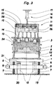
- 1, 2, 3, 4 and 5, 1 denotes a vibrating table.
- a model plate carrier 4 with a model 5, a molding frame 2 and a filling frame 3 is fastened on the vibration table 1.
- the model plate carrier 4 is used to hold a positive or a negative model plate 22.
- molding sand 24 is filled in the molding frame 2 and in the filling frame 3.
- the vibrating table 1 is supported on prestressed reactor springs 8 on an exciter frame 6.
- the excitation frame 6 itself is supported on insulation springs 7 which rest on a machine foundation 19.
- two unbalance motors 9 are arranged with opposite directions of rotation. At least one solid is on the machine foundation 19
- Stop bar 10 constructed with a support plate 20, which interacts with a support chuck 21 of the vibration table 1.
- a vertically movable multi-punch press head 11 is provided above the vibrating table 1.
- the multi-die press head 11 consists of three press units, the press housing 12, a mother plate 13 and a number of press dies 14. Each of these press units can be actuated individually and independently of the others.
- the press housing 12 has an outer piston / cylinder unit 16 with a pressure cylinder 17 and a pressure piston 18 and can be moved in the vertical direction.
- the mother plate 13 is slidably guided in the press housing 12 on the inner walls and is moved parallel to the direction of movement of the press housing by a plurality of inner pistons / cylinder units 25 installed in the press housing 12.
- the press punches 14 are slidably guided in the mother plate 13 parallel to the direction of movement of the mother plate 13 and are likewise moved by an inner piston / cylinder unit 26 installed in the press housing 12.
- the supply lines 27, 28 for a pressure medium to the inner piston / cylinder units 25, 26 of the press housing 12 are integrated in the cover 15 of the press housing 12.
- the sand metering device moves and the multi-stamp press head 11 moves in its place.
- a sinusoidal force acts on the vibration system consisting of the vibrating table 1, exciter frame 6, insulation springs 7 and reactor springs 8, which resonates with the rhythm of the force acting and the forced frequency, with a linear, vertical oscillating movement from the exciter frame 6 to the Vibration table 1 is transmitted.
- the ideal oscillation deflection can be set by adjusting the pretensioning force of the reactor springs 8 and the rotational speed of the unbalance motors 9 which can be infinitely regulated by means of a frequency converter, not shown.
- the molding sand 24 is fluidized by the vibration and distributed evenly in the molding frame 2, in the filling frame 3 and along the contours of the model 5.
- the complete multi-punch press head 11 is lowered in the vertical direction with the aid of the piston / cylinder unit 16 and moved into the sand, the press housing 12, the mother plate 13 and the Die 14 lie in a common press plane and thus form a contour press head.
- the molding sand 24 is uniformly pre-compressed and deaerated in the press housing 12 by the multi-stamp press head 11 with an increasing pressure force of the outer piston / cylinder unit 16 with the same internal pressure of the inner piston / cylinder units 25, 26.
- the pressure forces of the hydraulic systems are set so that the resulting total deflection of the insulation springs 7 and the reactor springs 8 of the vibration system is less than the distance between the support plate 20 of the stop beam 10 and the support chuck 21 of the vibrating table 1, ie the oscillating system vibrates freely at a high frequency without colliding with the stop beam 10.
- the frame of the press housing 12 is immersed further in the molding sand 24 with the help of the outer piston / cylinder unit 16 and the press rams 14 with the aid of the inner piston / cylinder unit 26, while the mother plate 13 remains and the associated inner piston / cylinder units 25 are gradually compressed at a balanced pressure.
- the immersion depth of the individual press punches 14 depends on the contour of the model 5, on the characteristics of the molding sand 24 and on the inner contour of the molding box 2.
- the vibration system vibrates with compressed insulation springs 7 and reactor springs 8 still free.
- a fourth phase the press-compression phase (see FIG. 4), the pressure in the outer piston / cylinder unit 16 and in the inner piston / cylinder units 25 assigned to the mother plate 13 is further increased, the frame of the press housing 12 and the mother plate 13 further compress the molding sand 24.
- the vibration system is based on the stop bar 10 and the frequency of the geared motors 9 is reduced; the pressing phase begins.
- a fifth phase the final compression phase (see FIG. 5)
- the back of the mold is pressed through the frame of the press housing with the help of the outer piston / cylinder unit 16 and the inner piston / cylinder units 25 at an optimal contact pressure with the vibration table 1 resting on the stop beam 12 and the mother plate 13 pressed up finally the lower edge of the frame of the press housing 12 falls below the parting line between the molding frame 2 and the filling frame 3 and the pressure in the outer piston / cylinder unit 16 is released via a drain valve, not shown.
- Suitable risers and pouring pits are either molded into the sand or cut into the molding sand after compaction.
- the determination of the respective amount of molding sand, the setting of the various compressive forces for the individual pressing phases, the setting of the preload of the reactor springs 8 and the changes in the drive frequencies for the unbalance motors are coordinated with the respective molding sand properties, which are carried out before each start of work using a standard test specimen using the ball impression method according to Brinell method is determined.
- press housing 12 such that individual press punches 14 or groups of press punches 14 can be acted upon separately.
- the press heads known as multi-rams, equipped with directly adjacent press rams work after a short press travel through the teeth of the sand grains (cutting angle) same as a flat press.
Abstract
Description
Die Erfindung betrifft ein Verfahren und eine Vorrichtung zur Durchführung des Verfahrens zum Verdichten von Giessereiformsand, bei welchem eine Progressionsverdichtung im Rüttelpressverfahren stattfindet, mit einem Vibrationstisch, einem Formrahmen, einem den Überschussand aufnehmenden Füllrahmen, einem aus einem Pressgehäuse mit einer Vielzahl von Pressstempeln bestehenden Multistempel-Presskopf und einer durch Federn abgestützten, mit Unwuchtmotoren bestückten Vibrationseinheit.The invention relates to a method and a device for carrying out the method for compacting foundry molding sand, in which a progressive compression takes place in the vibratory pressing method, with a vibrating table, a molding frame, a filling frame that absorbs the excess sand, a multi-stamp consisting of a press housing with a large number of press dies. Press head and a vibration unit supported by springs and equipped with unbalance motors.
Zum Verdichten von Giessereiformsand für die Herstellung von Sandformen in Formkasten, als auch für kastenlose Giessformteile, gibt es eine ganze Reihe bekannter Verfahren, welche alle das gleiche Ziel verfolgen, eine möglichst gleichmässige Härteverteilung im Formsand über den ganzen Bereich, insbesondere in den Randzonen der Sandform und unabhängig von der Form des Modellkörpers zu erreichen, um beim späteren Abgiessen der Form einen einwandfreien Guss zu erhalten.There is a whole series of known processes for compacting foundry mold sand for the production of sand molds in mold boxes, as well as for boxless mold parts, all of which have the same goal, the most uniform possible distribution of hardness in the mold sand over the entire area, especially in the edge zones of the sand mold and regardless of the shape of the model body, in order to obtain a perfect cast when the mold is subsequently poured off.
Neben dem bewährten Stampfen von Hand sind vor allem für die automatische Serienfertigung mechanisches Pressen, insbesondere Hochdruckpressen, mechanisches Rütteln mit Nachpressen, Vakuumpressen und das sogenannte Schiessverfahren, bei dem der Formsand unter Überdruck in den Formkasten geschossen wird, bekannt.In addition to the tried and tested tamping by hand, mechanical presses, in particular high-pressure presses, mechanical shaking with post-presses, vacuum presses and the so-called shooting process, in which the molding sand is shot into the molding box under excess pressure, are known above all for automatic series production.
Als vorteilhaftestes Verfahren mit befriedigendem Verdichtungsgrad bei jeder Modellform hat sich das Rüttelpressverfahren erwiesen, als Kombination von zwei Verfahren, bei welchem die Vorteile einer mechanischen Rütteleinrichtung mit den Vorteilen eines Verdichtungskopfes gepaart sind.The most advantageous method with a satisfactory degree of compaction for each model form has proven to be the vibrating press method, as a combination of two methods in which the advantages of a mechanical vibrating device are paired with the advantages of a compaction head.
Ein solches Verfahren und eine solche Einrichtung für die Herstellung von Giessereiformen in Formkästen ist mit der GB-A-2 130 511 bekannt geworden. Die Einrichtung umfasst einen auf Federn ruhenden Vibrationstisch mit Unwuchtmotoren, für die Aufnahme eines Formkastens, und einer über dem Vibrationstisch an einem Joch befestigten Presseinrichtung mit einer Vielzahl in der Höhe verstellbaren Pressstempeln. Die Pressstempel ruhen, einzeln vertikal verschiebbar angeordnet, in einer durch Kolben-Zylindereinheiten in der Höhe verstellbaren Tragplatte. Sie hängen lose in der Tragplatte und wirken durch ihr Eigengewicht auf die Oberfläche des in den Formkasten eingefüllten Formsandes, wenn die Tragplatte nach unten verschoben wird.
- In einer ersten Stufe wird ein Modell in einen Formkasten auf dem Vibrationstisch eingelegt;
- in einer zweiten Stufe wird Formsand mit einem Bindemittel bis an den oberen Rand des Formkastens eingefüllt;
- in einer dritten Stufe wird die Tragplatte mit den Pressstempeln nach unten verschoben, bis die Pressstempel auf der Oberfläche des Formsandes lose aufliegen;
- in einer vierten Stufe werden die Unwuchtmotoren eingeschaltet, wobei der Formsand durch die Vibration und die lose durch ihr Eigengewicht auf dem Formsand aufliegenden Pressstempel gefestigt wird.
- Sobald die gewünschte Festigung des Formsandes erreicht ist, werden die Unwuchtmotoren stillgesetzt, die Pressstempel hochgehoben und der Formkasten kann weggeführt werden.
- In a first stage, a model is placed in a molding box on the vibration table;
- in a second stage molding sand is filled with a binder up to the top of the molding box;
- in a third stage the support plate with the press rams is moved downwards until the press rams lie loosely on the surface of the molding sand;
- In a fourth stage, the unbalance motors are switched on, the molding sand being fixed by the vibration and the press rams lying loosely on the molding sand due to their own weight.
- As soon as the desired strengthening of the molding sand is achieved, the unbalance motors are stopped, the press rams are raised and the molding box can be removed.
Mit der CH-PS Nr. 662 072 A5 ist eine weitere Maschine für die Herstellung von Giessformen bekanntgeworden, welche ebenfalls dieses Rüttelpressverfahren vorsieht. Die Maschine umfasst eine Rahmenkonstruktion, durch die eine horizontale Fördereinrichtung hindurchführt, die als Zubringer und Wegführer für die von der Maschine zu behandelnden Gegenstände dient. Die Rahmenkonstruktion trägt oben eine Stampfeinrichtung mit einem aus einer Vielzahl von Fluidzylindern bestehenden, sogenannten Verdichtungskopf und unten eine Vibrationseinrichtung. Die Vibrationseinrichtung weist einen auf Federn abgestützen Amboss auf, der durch ein Hubmittel mit der Formherstellungsstation in Eingriff gebracht werden kann und wirkungsmässig mit einer ebenfalls auf Federn abgestützten Stossschwingeinrichtung verbunden ist. Beim Betrieb werden über die Fördereinrichtung die zur Formherstellung nötigen Gegenstände und Werkstoffe zugeführt. Sobald diese die richtige Lage in der Formherstellungsstation eingenommen haben, wird die Vibrationseinrichtung eingeschaltet und die vertikalen Schwingbewegungen auf den Amboss bzw. auf die Formherstellungsstation übertragen.With CH-PS No. 662 072 A5, another machine for the production of casting molds has become known, which also provides this vibratory pressing method. The machine comprises a frame construction through which a horizontal conveyor leads, which serves as a feeder and guide for the objects to be treated by the machine. The frame construction carries a ramming device at the top with a so-called compression head consisting of a plurality of fluid cylinders and a vibration device at the bottom. The vibrating device has an anvil supported on springs, which can be brought into engagement with the mold-making station by a lifting means and is effectively connected to a shock-vibrating device also supported on springs. During operation, the objects and materials required for mold production are fed in via the conveyor. As soon as they have taken the correct position in the mold production station, the vibrating device is switched on and the vertical oscillating movements are transmitted to the anvil or to the mold production station.
Ein Nachteil der letztgenannten liegt darin, dass die Rüttelbewegung durch den Aufprall des Ambosses oder des Hammers auf die Unterseite des Presstisches erzeugt wird, wobei eine sehr starke Schlagverzögerung und erheblicher Lärm ensteht.A disadvantage of the latter is that the shaking movement is generated by the impact of the anvil or hammer on the underside of the press table, which results in a very strong impact delay and considerable noise.
Ein Nachteil von beiden bekannten vorrichtungen liegt darin, dass der aus einer Vielzahl von presszylindern bestehende Verdichtungskopf beim Pressen vor allem im Bereich der Verdichtungsköpfe den Sand verdichtet, während zwischen den einzelnen Verdichtungsköpfen und um die Verdichtungsköpfe selbst ungepresster und teilweise loser Sand vorherrschen. Es hat sich zudem gezeigt, dass die meisten bekannten Vorrichtungen zum Herstellen von Giessformen den gegebenen Sandeigenschaften nicht vollumfänglich Rechnung tragen können.A disadvantage of both known devices is that the compacting head, which consists of a large number of press cylinders, compresses the sand, particularly in the area of the compacting heads, while unpressed and partially loose sand predominates between the individual compacting heads and around the compacting heads themselves. It has also been shown that most known devices for the production of casting molds cannot take full account of the given sand properties.
Der Erfindung liegt deshalb die Aufgabe zugrunde, die ungenügende Berücksichtigung der Sandeigenschaft bei verschiedenen Betriebssanden zu verbessern und ein Verfahren und eine Vorrichtung zur Durchführung des Verfahrens zum Verdichten von Giessereiformsand für die Herstellung von Giessformteilen vorzuschlagen, mit denen eine verfahrensmässige und betriebliche Optimierung der sandabhängigen Formkenngrössen erwirkt werden kann, damit sich sowohl eine genügende Formhärte als auch eine ideale Gasdurchlässigkeit der Formteile ergibt.The invention is therefore based on the object of improving the inadequate consideration of the sand properties in various operating sands and to propose a method and a device for carrying out the method for compacting foundry mold sand for the production of mold parts, with which a procedural and operational optimization of the sand-dependent shape parameters is achieved can be so that there is both a sufficient mold hardness and an ideal gas permeability of the molded parts.
Diese Aufgabe wird durch die in den Ansprüchen 1 und 2 gekennzeichnete Erfindung gelöst.This object is achieved by the invention characterized in
Die durch die Erfindung erreichten Vorteile sind im wesentlichen darin zu sehen, dass durch eine flexible Einstellung der Verdichtungsparameter bei sich ändernden Sandeigenschaften, gemäss einer im voraus an einem Normprüfkörper mit dem Kugeleindruckverfahren nach der Brinell-Methode bestimmten Formhärte, und bei stark variierenden Modellkonturen eine gleichmässige Verdichtung auch bei Giessformteilen mit stark unterschiedlichen Modellkonturen möglich ist, dass ein Überpressen oder Unterpressen in Extrembereichen und die sogenannte Brückenbildung verhindert werden und saubere und kleine Eingusstümpel ausführbar sind.The advantages achieved by the invention are essentially to be seen in the fact that a flexible adjustment of the compression parameters in the case of changing sand properties, in accordance with a hardness of the shape determined beforehand on a standard test specimen using the ball indentation method using the Brinell method, and uniformity in the case of widely varying model contours Compression is also possible with molded parts with very different model contours that overpressing or underpressing in extreme areas and the so-called bridging are prevented and clean and small casting puddles can be carried out.
Mit der über einen Frequenzumformer stufenlos einstellbaren Frequenz der Unwuchtmotoren der Vibrationseinheit ist es zudem möglich, die bei herkömmlichen Rüttelpressmaschinen bekannten, geräuschintensiven Ambossschläge durch eine beinahe lautlose und wirksamere Vibro-Erregung des Erfindungsgegenstandes zu ersetzen. Durch das Zurücknehmen der Vibrationsfrequenz während der Endpressphase, wenn die Vibrationseinheit auf den Stopbalken aufsetzt, können die Unwuchtmotoren kontinuierlich durchgefahren werden, was neben den praktisch lautlosen Übergängen auch eine rationelle Taktfolge ermöglicht.With the frequency of the unbalance motors of the vibration unit, which can be infinitely adjusted via a frequency converter, it is also possible to replace the noise-intensive anvil strokes known from conventional vibratory press machines with an almost silent and more effective vibro excitation of the subject matter of the invention. By reducing the vibration frequency during the final pressing phase, when the vibration unit is placed on the stop bar, the unbalance motors can be run continuously, which besides the practically silent transitions also enables a rational clock sequence.
Auf beiliegenden Zeichnungen ist ein Ausführungsbeispiel der Erfindung dargestellt, das im folgenden näher erläutert wird.On the accompanying drawings, an embodiment of the invention is shown, which is explained in more detail below.
Es zeigen:
- Fig. 1 einen Aufriss einer Vorrichtung zur Herstellung von Giessformteilen im Schnitt dargestellt, in einer ersten Phase, der Vorvibrierphase,
- Fig. 2 einen Aufriss der Vorrichtung wie Fig. 1, in einer zweiten Phase, der Konsolidierungs- und Entlüftungsphase,
- Fig. 3 einen Aufriss der Vorrichtung wie Fig. 1 in einer dritten Phase, der Vorverdichtungsphase,
- Fig. 4 einen Aufriss der Vorrichtung wie Fig. 1 in einer vierten Phase, der Press-Verdichtungsphase,
- Fig. 5 einen Aufriss der Vorrichtung wie Fig. 1 in einer fünften Phase, der Endverdichtungsphase.
- 1 shows an elevation of a device for the production of mold parts in section, in a first phase, the pre-vibrating phase,
- 2 shows an elevation of the device as in FIG. 1, in a second phase, the consolidation and venting phase,
- 3 shows an elevation of the device like FIG. 1 in a third phase, the pre-compression phase,
- 4 shows an elevation of the device as in FIG. 1 in a fourth phase, the press-compression phase,
- Fig. 5 is an elevation of the device like Fig. 1 in a fifth phase, the final compression phase.
In den Fig. 1, 2, 3, 4 und 5 ist mit 1 ein Vibrationstisch bezeichnet. Auf dem Vibrationstisch 1 ist ein Modellplattenträger 4 mit einem Modell 5, einem Formrahmen 2 und einem Füllrahmen 3 befestigt. Der Modellplattenträger 4 dient zur Aufnahme einer Positiv- oder einer Negativmodellplatte 22. Über dem Modell 5 ist im Formrahmen 2 und im Füllrahmen 3 Formsand 24 aufgefüllt. Der Vibrationstisch 1 ist auf vorgespannten Reaktorfedern 8 auf einem Erregerrahmen 6 gelagert. Der Erregerrahmen 6 selbst ist auf Isolationsfedern 7 abgestützt, welche auf einem Maschinenfundament 19 aufliegen. Am Erregerrahmen 6 sind zwei Unwuchtmotoren 9 mit gegenläufigem Drehsinn angeordnet. Auf dem Maschinenfundament 19 ist mindestens ein fester Stopbalken 10 aufgebaut mit einer Auflageplatte 20, welche mit einem Auflagefutter 21 des Vibrationstisches 1 zusammenspielt. Über dem Vibrationstisch 1 ist ein vertikal bewegbarer Multistempel-Presskopf 11 vorgesehen. Der Multistempel-Presskopf 11 besteht aus drei Presseinheiten, dem Pressgehäuse 12, einer Mutterplatte 13 und einer Anzahl von Pressstempeln 14. Jede dieser Presseinheiten ist einzeln und unabhängig von den andern hydraulisch betätigbar. Das Pressgehäuse 12 besitzt eine äussere Kolben/Zylinder-Einheit 16 mit einem Druckzylinder 17 und einem Druckkolben 18 und ist in vertikaler Richtung bewegbar. Die Mutterplatte 13 ist im Pressgehäuse 12 an den Innenwänden gleitend geführt und wird durch mehrere im Pressgehäuse 12 eingebaute innere Kolben/Zylindereinheiten 25 parallel zur Bewegungsrichtung des Pressgehäuses bewegt. Die Pressstempel 14 sind in der Mutterplatte 13 parallel zur Bewegungsrichtung der Mutterplatte 13 gleitend geführt und werden ebenfalls durch je eine im Pressgehäuse 12 eingebaute innere Kolben/Zylindereinheit 26 bewegt. Die Zuleitungen 27, 28 für ein Druckmedium zu den inneren Kolben/Zylinder-Einheiten 25, 26 des Pressgehäuses 12 sind im Deckel 15 des Pressgehäuses 12 integriert.1, 2, 3, 4 and 5, 1 denotes a vibrating table. A
Die vorstehend beschriebene Vorrichtung zum Verdichten von Giessereiformsand für die Herstellung von Giessformteilen arbeitet wie folgt:The device described above for compacting foundry mold sand for the production of mold parts works as follows:
In einer ersten Phase, der Vorvibrierphase (siehe Fig. 1), wird durch ein nicht dargestelltes Sand-Dosiergerät eine auf die Eigenschaften des Formsandes 24 und auf die Form und Grösse des Modelles 5 ausgerichtete, vorbestimmte Menge Formsand 24, bei verfahrenem Multistempel-Presskopf 11 und bei eingeschalteten Unwuchtmotoren 9, über das auf der Modellplatte 22 angeordnete Modell 5 in den Formrahmen 2 bzw. in den Füllrahmen 3 eingefüllt. Nach der Beendigung des Auffüllvorganges verfährt das Sand-Dosiergerät und an dessen Stelle fährt der Multistempel-Presskopf 11 ein. Durch den gegenläufigen Drehsinn der Unwuchtmotoren 9 wirkt eine sinusförmige Kraft auf das aus Vibrationstisch 1, Erregerrahmen 6, Isolationsfedern 7 und Reaktorfedern 8 bestehende Schwingsystem ein, welches im Rhythmus der einwirkenden Kraft und der aufgezwungenen Frequenz mitschwingt, wobei eine lineare, vertikale Schwingbewegung vom Erregerrahmen 6 auf den Vibrationstisch 1 übertragen wird. Durch die Einstellung der Vorspannkraft der Reaktorfedern 8 und die mittels eines nicht dargestellten Frequenzumformers stufenlos regulierbare Drehzahl der Unwuchtmotoren 9 lässt sich der ideale Schwingausschlag einstellen. Der Formsand 24 wird durch die Vibration fluidisiert und gleichmässig im Formrahmen 2, im Füllrahmen 3 und entlang der Konturen des Modells 5 verteilt. Die im wesentlichen vom Feuchtigkeitsgehalt abhängigen inneren Reibungs- und Haftkräfte des zu verdichtenden Formsandes werden unter der Einwirkung der Schwingbewegungen verringert, so dass sich die einzelnen Sandkörner unter der Wirkung der Schwerkraft nach unten bewegen und sich das Schüttgut verdichtet. Gleichzeitig werden Brückenbildungen des Formsandes auch bei komplizierten Modellen ausgeschlossen.In a first phase, the pre-vibrating phase (see FIG. 1), a predetermined amount of
In einer zweiten Phase, der Konsolidierungs- und Entlüftungsphase (siehe Fig. 2) wird der komplette Multistempel-Presskopf 11 mit Hilfe der Kolben/Zylindereinheit 16 in vertikaler Richtung abgesenkt und in den Sand eingefahren, wobei das Pressgehäuse 12, die Mutterplatte 13 und die Pressstempel 14 in einer gemeinsamen Pressebene liegen und so einen Konturenpresskopf bilden. In diesem Zustand wird der Formsand 24 mit dem Multistempel-Presskopf 11 mit einer ansteigenden Druckkraft der äusseren Kolben/Zylindsereinheit 16 bei gleichem Innendruck der inneren Kolben/Zylindereinheiten 25, 26 im Pressgehäuse 12 gleichmässig vorverdichtet und entlüftet. Die Druckkräfte der Hydraulik-Systeme sind so eingestellt, dass die dabei entstehende Gesamteinfederung der Isolationsfedern 7 und der Reaktorfedern 8 des Schwingsystemes kleiner ist als der Abstand zwischen der Auflageplatte 20 des Stopbalkens 10 und dem Auflagefutter 21 des Vibrationstisches 1, d.h. das Schwingsystem schwingt bei grosser Frequenz frei, ohne auf den Stopbalken 10 aufzufahren.In a second phase, the consolidation and venting phase (see FIG. 2), the complete
In einer dritten Phase, der Vorverdichtungsphase (siehe Fig. 3), tauchen der Rahmen des Pressgehäuses 12 mit Hilfe der äusseren Kolben/Zylindereinheit 16 und die Pressstempel 14 mit Hilfe der inneren Kolben/Zylindereinheiten 26 weiter in den Formsand 24 ein, während die Mutterplatte 13 stehen bleibt und die zugehörigen inneren Kolben/Zylindereinheiten 25 bei ausgeglichenem Druck allmählich zusammengedrückt werden. Die Eintauchtiefe der einzelnen Pressstempel 14 richtet sich nach der Kontur des Modells 5, nach der Charakteristik des Formsandes 24 und nach der Innenkontur des Formkastens 2. Trotz zunehmendem Druck in der äusseren Kolben/Zylindereinheit 16 und in den inneren Kolben/Zylindereinheiten 26 schwingt das Schwingsystem bei zusammengepressten Isolations- 7 und Reaktorfedern 8 noch frei mit.In a third phase, the pre-compression phase (see FIG. 3), the frame of the
In einer vierten Phase, der Press-Verdichtungs-Phase (siehe Fig. 4), wird der Druck in der äusseren Kolben/Zylindereinheit 16 und in den der Mutterplatte 13 zugeordneten inneren Kolben/Zylindereinheiten 25 weiter erhöht, wobei der Rahmen des Pressgehäuses 12 und die Mutterplatte 13 den Formsand 24 weiter verdichten. Das Schwingsystem setzt auf dem Stopbalken 10 auf und die Frequenz der Getriebemotoren 9 wird zurückgenommen; die Pressphase beginnt.In a fourth phase, the press-compression phase (see FIG. 4), the pressure in the outer piston /
In einer fünften Phase, der Endverdichtungs-Phase (siehe Fig. 5), wird der Formrücken bei einem optimalen Anpressdruck bei auf den Stopbalken aufliegendem Vibrationstisch 1 mit Hilfe der äusseren Kolben/Zylindereinheit 16 und der inneren Kolben/Zylindereinheiten 25 durch den Rahmen des Pressgehäuses 12 und die Mutterplatte 13 nachgepresst bis schlussendlich die Unterkante des Rahmens des Pressgehäuses 12 die Trennfuge zwischen dem Formrahmen 2 und dem Füllrahmen 3 unterschreitet und der Druck in der äusseren Kolben/Zylindereinheit 16 über ein nicht dargestelltes Ablassventil abgelassen wird.In a fifth phase, the final compression phase (see FIG. 5), the back of the mold is pressed through the frame of the press housing with the help of the outer piston /
Geeignete Steiger und Eingusstümpel werden entweder in den Sand eingeformt oder nach der Verdichtung in den Formsand geschnitten. Die Bestimmung der jeweiligen Formsandmenge, die Einstellung der verschiedenen Druckkräfte für die einzelnen Pressphasen, die Einstellung der Vorspannung der Reaktorfedern 8 sowie die Änderungen der Antriebsfrequenzen für die Unwuchtmotoren werden abgestimmt auf die jeweilige Formsandeigenschaft, welche vor jeder Arbeitsaufnahme anhand eines Normprüfkörpers mit dem Kugeleindruckverfahren nach der Brinell-Methode festgestellt wird.Suitable risers and pouring pits are either molded into the sand or cut into the molding sand after compaction. The determination of the respective amount of molding sand, the setting of the various compressive forces for the individual pressing phases, the setting of the preload of the reactor springs 8 and the changes in the drive frequencies for the unbalance motors are coordinated with the respective molding sand properties, which are carried out before each start of work using a standard test specimen using the ball impression method according to Brinell method is determined.
Es ist ohne weiteres denkbar, das Pressgehäuse 12 so auszubilden, dass einzelne Pressstempel 14 oder Gruppen von Pressstempeln 14 separat beaufschlagbar sind. Durch einen gewissen Abstand zwischen den einzelnen Pressstempeln oder durch das wahlweise Auslassen einzelner Pressstempel beim Pressen ist ein weit besseres Verdichten des Formsandes möglich, wirken doch die als Mehrstempel bekannten, mit unmittelbar aneinandergereihten Pressstempeln ausgerüsteten Presshäupter nach kurzem Pressweg durch die Verzahnung der Sandkörner (Schnittwinkel) gleich wie eine Flachpresse.It is readily conceivable to design the
Claims (6)
characterised by a stepwise preliminary compaction, which is preprogrammed matched to the respective state of the moulding sand (24) ascertained at a test body by the Brinell method and in which
characterised thereby,
that the multi-die press head (11) displays three press units each independent of the other and that a steplessly regulable frequency converter is associated with the eccentric motors (9).
characterised thereby,
that the three press units display a press housing (12), which is movable in vertical direction by an external piston-cylinder unit (16), a mother matrix plate (13), which is borne to be displaceable at the inward walls in the press housing (12) and parallelly to the direction of movement of the press housing (12) and which is movable by internal piston-cylinder units (25), and the press dies (14), which are borne in the mother matrix plate (13) to be displaceable parallelly to the direction of movement of the press housing (12) and movable by further internal piston-cylinder units (26).
characterised thereby,
that a separate feed (28) for a pressure medium to the press dies (14) is associated with each individual internal piston-cylinder unit (26) or a group of internal piston-cylinder units (26).
characterised thereby,
that in the third phase, groups of press dies (14) and/or individual press dies (14) are impressed into the moulding sand (24) in alternation by the same pressure force or by different pressure forces.
characterised thereby,
that in the third phase, groups of press dies (14) and/or individual press dies (14) are impressed into the moulding sand (24) in alternation to an equal adjustable depth or to different adjustable depths.
Priority Applications (1)
| Application Number | Priority Date | Filing Date | Title |
|---|---|---|---|
| AT89100932T ATE76341T1 (en) | 1988-02-04 | 1989-01-20 | METHOD AND DEVICE FOR CARRYING OUT THE METHOD OF COMPACTION OF FOUNDRY MOLDING SAND. |
Applications Claiming Priority (2)
| Application Number | Priority Date | Filing Date | Title |
|---|---|---|---|
| CH396/88 | 1988-02-04 | ||
| CH39688 | 1988-02-04 |
Publications (2)
| Publication Number | Publication Date |
|---|---|
| EP0326870A1 EP0326870A1 (en) | 1989-08-09 |
| EP0326870B1 true EP0326870B1 (en) | 1992-05-20 |
Family
ID=4186062
Family Applications (1)
| Application Number | Title | Priority Date | Filing Date |
|---|---|---|---|
| EP89100932A Expired - Lifetime EP0326870B1 (en) | 1988-02-04 | 1989-01-20 | Method and machine for compacting foundry sand |
Country Status (4)
| Country | Link |
|---|---|
| EP (1) | EP0326870B1 (en) |
| AT (1) | ATE76341T1 (en) |
| DE (1) | DE58901439D1 (en) |
| ES (1) | ES2033024T3 (en) |
Cited By (2)
| Publication number | Priority date | Publication date | Assignee | Title |
|---|---|---|---|---|
| CN108856656A (en) * | 2018-07-18 | 2018-11-23 | 安徽宏华铸造有限公司 | A kind of box moulding equipment for electric motor end cap casting |
| CN110744015A (en) * | 2019-11-08 | 2020-02-04 | 象山旭雯钢铁科技有限公司 | Sand casting mould is with filling device fast |
Families Citing this family (6)
| Publication number | Priority date | Publication date | Assignee | Title |
|---|---|---|---|---|
| WO2005056279A1 (en) * | 2003-12-14 | 2005-06-23 | GEDIB Ingenieurbüro und Innovationsberatung GmbH | Device for compacting granulated moulding materials |
| CN100464896C (en) * | 2006-06-07 | 2009-03-04 | 陈岳海 | Mold press for sand-cast and method for producing sand-cast using the mold press |
| DE102014001515A1 (en) * | 2014-02-07 | 2015-08-13 | Schenck Process Gmbh | vibrating machine |
| CN108500218A (en) * | 2018-06-14 | 2018-09-07 | 临海市微能铸机有限公司 | A kind of multiple contact compacting full-automatic boxless moulding machine of horizontal parting |
| CN109175266A (en) * | 2018-10-09 | 2019-01-11 | 禹州市毛吕铸造有限公司 | A kind of sand casting compaction apparatus |
| CN115871081B (en) * | 2022-11-16 | 2023-09-01 | 福建群峰机械有限公司 | Brick making process of brick making machine pressing head and double-layer pavement brick |
Family Cites Families (6)
| Publication number | Priority date | Publication date | Assignee | Title |
|---|---|---|---|---|
| DE271903C (en) * | ||||
| US2959828A (en) * | 1958-06-30 | 1960-11-15 | Herman Pneumatic Machine Co | Foundry mold forming |
| US2985927A (en) * | 1958-10-16 | 1961-05-30 | Herman Pneumatic Machine Co | Foundry mold forming apparatus |
| US3385347A (en) * | 1966-01-24 | 1968-05-28 | Osborn Mfg Co | Jolt molding machine |
| AU567107B2 (en) * | 1982-11-12 | 1987-11-12 | General Kinematics Corporation | Mould for metal casting using vibration and gravity head |
| CA1221811A (en) * | 1983-02-02 | 1987-05-19 | General Kinematics Corporation | Mold forming machine for a foundry |
-
1989
- 1989-01-20 AT AT89100932T patent/ATE76341T1/en not_active IP Right Cessation
- 1989-01-20 DE DE8989100932T patent/DE58901439D1/en not_active Expired - Fee Related
- 1989-01-20 EP EP89100932A patent/EP0326870B1/en not_active Expired - Lifetime
- 1989-01-20 ES ES198989100932T patent/ES2033024T3/en not_active Expired - Lifetime
Cited By (2)
| Publication number | Priority date | Publication date | Assignee | Title |
|---|---|---|---|---|
| CN108856656A (en) * | 2018-07-18 | 2018-11-23 | 安徽宏华铸造有限公司 | A kind of box moulding equipment for electric motor end cap casting |
| CN110744015A (en) * | 2019-11-08 | 2020-02-04 | 象山旭雯钢铁科技有限公司 | Sand casting mould is with filling device fast |
Also Published As
| Publication number | Publication date |
|---|---|
| EP0326870A1 (en) | 1989-08-09 |
| ATE76341T1 (en) | 1992-06-15 |
| DE58901439D1 (en) | 1992-06-25 |
| ES2033024T3 (en) | 1993-03-01 |
Similar Documents
| Publication | Publication Date | Title |
|---|---|---|
| DE2832627A1 (en) | VIBRATING ROCKING DEVICE FOR MOLDING CONCRETE BLOCK | |
| WO2011127928A1 (en) | Device and method for producing pre-cast concrete blocks and corresponding mold | |
| EP0326870B1 (en) | Method and machine for compacting foundry sand | |
| DE102005002497B3 (en) | Method and device for producing hollow building blocks | |
| DE3638207A1 (en) | Process for producing purpose-made concrete blocks, and apparatus for carrying out the process | |
| DE2843598A1 (en) | METHOD AND DEVICE FOR COMPRESSING FOUNDRY SAND | |
| DE2508074B2 (en) | Method and device for shaping products from semi-dry, pourable masses | |
| DE648303C (en) | Ruettelforming machine | |
| DE3004642A1 (en) | Concrete-block material-compacting mechanism - has vibrator adjustable for height, actuated by lifting mechanism | |
| DE2552852C3 (en) | Method for compacting molded bodies made of concrete or the like. plastic masses | |
| DE1097622B (en) | Method and device for uniform compression of the molding sand in compression molding machines | |
| DE102011054488A1 (en) | Device for manufacturing e.g. paving stones in sequential manufacturing cycles, has load lower part connected with mold upper part, load upper part connected with machine, and control device variably controlling fluid pressures in bellows | |
| DE2453634A1 (en) | Machine for vibration-compaction of concrete castings - applies forced vibration from below and sympathetic vibration from above | |
| DE3342314C2 (en) | ||
| DE1963640C3 (en) | Vibrating system for the production of moldings by compression | |
| DE3048181C2 (en) | Device for producing compacted molded bodies made of concrete or the like. | |
| CH671897A5 (en) | Moulding machine for producing sand-filled moulds - in which distribution and compaction of the sand is improved in a vibrating and compression process | |
| DE102004063272A1 (en) | Equipment consolidating concrete mixture, compares actual- and reference profiles of pressure variation to control applied mechanical pressure and vibration | |
| EP1281492A1 (en) | Compaction device | |
| DE3329585C2 (en) | ||
| EP0285821A2 (en) | Process and device for compacting moulding materials for foundry moulds | |
| EP1375098A2 (en) | Method and filling station for closing cores | |
| DE923659C (en) | Method and device for producing sugar strips, plates or cubes by means of pressing devices set in vibration | |
| DE10061449A1 (en) | Compacting device for compacting product bodies consisting of granular mass | |
| DE19601352C2 (en) | Device for compacting earth-moist concrete |
Legal Events
| Date | Code | Title | Description |
|---|---|---|---|
| PUAI | Public reference made under article 153(3) epc to a published international application that has entered the european phase |
Free format text: ORIGINAL CODE: 0009012 |
|
| AK | Designated contracting states |
Kind code of ref document: A1 Designated state(s): AT CH DE ES FR GB IT LI SE |
|
| 17P | Request for examination filed |
Effective date: 19891216 |
|
| 17Q | First examination report despatched |
Effective date: 19910807 |
|
| GRAA | (expected) grant |
Free format text: ORIGINAL CODE: 0009210 |
|
| AK | Designated contracting states |
Kind code of ref document: B1 Designated state(s): AT CH DE ES FR GB IT LI SE |
|
| REF | Corresponds to: |
Ref document number: 76341 Country of ref document: AT Date of ref document: 19920615 Kind code of ref document: T |
|
| REF | Corresponds to: |
Ref document number: 58901439 Country of ref document: DE Date of ref document: 19920625 |
|
| GBT | Gb: translation of ep patent filed (gb section 77(6)(a)/1977) | ||
| ET | Fr: translation filed | ||
| ITF | It: translation for a ep patent filed |
Owner name: MODIANO & ASSOCIATI S.R.L. |
|
| PGFP | Annual fee paid to national office [announced via postgrant information from national office to epo] |
Ref country code: GB Payment date: 19921207 Year of fee payment: 5 |
|
| PGFP | Annual fee paid to national office [announced via postgrant information from national office to epo] |
Ref country code: FR Payment date: 19921215 Year of fee payment: 5 |
|
| PGFP | Annual fee paid to national office [announced via postgrant information from national office to epo] |
Ref country code: SE Payment date: 19921216 Year of fee payment: 5 |
|
| PGFP | Annual fee paid to national office [announced via postgrant information from national office to epo] |
Ref country code: DE Payment date: 19921221 Year of fee payment: 5 |
|
| PGFP | Annual fee paid to national office [announced via postgrant information from national office to epo] |
Ref country code: ES Payment date: 19930115 Year of fee payment: 5 |
|
| PGFP | Annual fee paid to national office [announced via postgrant information from national office to epo] |
Ref country code: AT Payment date: 19930121 Year of fee payment: 5 |
|
| REG | Reference to a national code |
Ref country code: ES Ref legal event code: FG2A Ref document number: 2033024 Country of ref document: ES Kind code of ref document: T3 |
|
| PLBE | No opposition filed within time limit |
Free format text: ORIGINAL CODE: 0009261 |
|
| STAA | Information on the status of an ep patent application or granted ep patent |
Free format text: STATUS: NO OPPOSITION FILED WITHIN TIME LIMIT |
|
| PGFP | Annual fee paid to national office [announced via postgrant information from national office to epo] |
Ref country code: CH Payment date: 19930416 Year of fee payment: 5 |
|
| 26N | No opposition filed | ||
| PG25 | Lapsed in a contracting state [announced via postgrant information from national office to epo] |
Ref country code: GB Effective date: 19940120 Ref country code: AT Effective date: 19940120 |
|
| PG25 | Lapsed in a contracting state [announced via postgrant information from national office to epo] |
Ref country code: SE Effective date: 19940121 Ref country code: ES Free format text: LAPSE BECAUSE OF NON-PAYMENT OF DUE FEES Effective date: 19940121 |
|
| PG25 | Lapsed in a contracting state [announced via postgrant information from national office to epo] |
Ref country code: LI Effective date: 19940131 Ref country code: CH Effective date: 19940131 |
|
| GBPC | Gb: european patent ceased through non-payment of renewal fee |
Effective date: 19940120 |
|
| PG25 | Lapsed in a contracting state [announced via postgrant information from national office to epo] |
Ref country code: FR Effective date: 19940930 |
|
| REG | Reference to a national code |
Ref country code: CH Ref legal event code: PL |
|
| PG25 | Lapsed in a contracting state [announced via postgrant information from national office to epo] |
Ref country code: DE Effective date: 19941001 |
|
| REG | Reference to a national code |
Ref country code: FR Ref legal event code: ST |
|
| EUG | Se: european patent has lapsed |
Ref document number: 89100932.6 Effective date: 19940810 |
|
| REG | Reference to a national code |
Ref country code: ES Ref legal event code: FD2A Effective date: 19990201 |
|
| PG25 | Lapsed in a contracting state [announced via postgrant information from national office to epo] |
Ref country code: IT Free format text: LAPSE BECAUSE OF NON-PAYMENT OF DUE FEES;WARNING: LAPSES OF ITALIAN PATENTS WITH EFFECTIVE DATE BEFORE 2007 MAY HAVE OCCURRED AT ANY TIME BEFORE 2007. THE CORRECT EFFECTIVE DATE MAY BE DIFFERENT FROM THE ONE RECORDED. Effective date: 20050120 |