EP0326859B1 - Table equipment - Google Patents
Table equipment Download PDFInfo
- Publication number
- EP0326859B1 EP0326859B1 EP89100820A EP89100820A EP0326859B1 EP 0326859 B1 EP0326859 B1 EP 0326859B1 EP 89100820 A EP89100820 A EP 89100820A EP 89100820 A EP89100820 A EP 89100820A EP 0326859 B1 EP0326859 B1 EP 0326859B1
- Authority
- EP
- European Patent Office
- Prior art keywords
- counterweight
- frame
- equipment according
- movable table
- guide
- Prior art date
- Legal status (The legal status is an assumption and is not a legal conclusion. Google has not performed a legal analysis and makes no representation as to the accuracy of the status listed.)
- Expired - Lifetime
Links
- 230000007246 mechanism Effects 0.000 claims description 18
- 239000012530 fluid Substances 0.000 claims description 16
- 230000005540 biological transmission Effects 0.000 claims description 6
- 230000008878 coupling Effects 0.000 claims description 3
- 238000010168 coupling process Methods 0.000 claims description 3
- 238000005859 coupling reaction Methods 0.000 claims description 3
- 230000001133 acceleration Effects 0.000 description 6
- 230000000694 effects Effects 0.000 description 3
- 230000005484 gravity Effects 0.000 description 3
- 230000002706 hydrostatic effect Effects 0.000 description 3
- 239000004065 semiconductor Substances 0.000 description 3
- 238000010276 construction Methods 0.000 description 2
- 230000004044 response Effects 0.000 description 2
- 230000008859 change Effects 0.000 description 1
- 238000010586 diagram Methods 0.000 description 1
- 238000003754 machining Methods 0.000 description 1
- 238000000034 method Methods 0.000 description 1
- 238000003801 milling Methods 0.000 description 1
- 230000004048 modification Effects 0.000 description 1
- 238000012986 modification Methods 0.000 description 1
- 230000000630 rising effect Effects 0.000 description 1
Images
Classifications
-
- B—PERFORMING OPERATIONS; TRANSPORTING
- B23—MACHINE TOOLS; METAL-WORKING NOT OTHERWISE PROVIDED FOR
- B23Q—DETAILS, COMPONENTS, OR ACCESSORIES FOR MACHINE TOOLS, e.g. ARRANGEMENTS FOR COPYING OR CONTROLLING; MACHINE TOOLS IN GENERAL CHARACTERISED BY THE CONSTRUCTION OF PARTICULAR DETAILS OR COMPONENTS; COMBINATIONS OR ASSOCIATIONS OF METAL-WORKING MACHINES, NOT DIRECTED TO A PARTICULAR RESULT
- B23Q1/00—Members which are comprised in the general build-up of a form of machine, particularly relatively large fixed members
- B23Q1/25—Movable or adjustable work or tool supports
-
- B—PERFORMING OPERATIONS; TRANSPORTING
- B23—MACHINE TOOLS; METAL-WORKING NOT OTHERWISE PROVIDED FOR
- B23Q—DETAILS, COMPONENTS, OR ACCESSORIES FOR MACHINE TOOLS, e.g. ARRANGEMENTS FOR COPYING OR CONTROLLING; MACHINE TOOLS IN GENERAL CHARACTERISED BY THE CONSTRUCTION OF PARTICULAR DETAILS OR COMPONENTS; COMBINATIONS OR ASSOCIATIONS OF METAL-WORKING MACHINES, NOT DIRECTED TO A PARTICULAR RESULT
- B23Q11/00—Accessories fitted to machine tools for keeping tools or parts of the machine in good working condition or for cooling work; Safety devices specially combined with or arranged in, or specially adapted for use in connection with, machine tools
- B23Q11/001—Arrangements compensating weight or flexion on parts of the machine
- B23Q11/0017—Arrangements compensating weight or flexion on parts of the machine compensating the weight of vertically moving elements, e.g. by balancing liftable machine parts
-
- B—PERFORMING OPERATIONS; TRANSPORTING
- B23—MACHINE TOOLS; METAL-WORKING NOT OTHERWISE PROVIDED FOR
- B23Q—DETAILS, COMPONENTS, OR ACCESSORIES FOR MACHINE TOOLS, e.g. ARRANGEMENTS FOR COPYING OR CONTROLLING; MACHINE TOOLS IN GENERAL CHARACTERISED BY THE CONSTRUCTION OF PARTICULAR DETAILS OR COMPONENTS; COMBINATIONS OR ASSOCIATIONS OF METAL-WORKING MACHINES, NOT DIRECTED TO A PARTICULAR RESULT
- B23Q3/00—Devices holding, supporting, or positioning work or tools, of a kind normally removable from the machine
- B23Q3/18—Devices holding, supporting, or positioning work or tools, of a kind normally removable from the machine for positioning only
Definitions
- This invention relates to a table equipment having a table which moves in a line inclined to the horizontal plane.
- the table equipment used in machine tools or other machines has a table which moves along a horizontal plane.
- a type of table equipment having a table which can move in the vertical direction is required for some machining methods.
- the driving force to move the table varies with its moving direction since the table is subjected to the effect of gravitational acceleration. More specifically, to raise the movable table, a driving force which is the frictional force plus its gravity is required. To lower the movable table, a driving force which is the frictional force less its gravity is required.
- the table equipment requires a motor which outputs force great enough to raise the table.
- the greater the output force of a motor the larger the motor, and the more expensive the motor.
- the table equipment must inevitably be relatively large as a whole and comparatively expensive.
- a motor which generates a large driving force has a large inertia during its operation and has a poor response to operation signals. Therefore, it is impossible to position the movable table at high speed.
- Table equipment which solves the above problem is disclosed in Japanese Patent Laid-Open Nos, 62-68207, 62-68208, 62-68209 62-68210, all filed by the assignee of the present application.
- table equipment is known from DE-C-633 122 defining the closest prior art.
- a movable table is connected with a counterweight equal to the total weight thereof in such a way that the counterweight can move vertically, thereby eliminating the effect of the gravity acting on the movable table. This makes it possible to position the movable table accurately at high speed and in short-time cycles.
- the equipment is large in overall size because the weight of the counterweight needs to be equal to that of the movable table and the members fixed thereon.
- This invention has been made to solve the above problem and has as its object to provide a compact table equipment capable of moving, at high speed and by a relatively small driving force, a movable table, the moving vector of which includes a component in the direction of gravitational acceleration and also capable of positioning the movable table accurately and in short-time cycles.
- table equipment comprises a frame; a table for supporting an object, and movable relative to said frame; a guide for guiding said table on said frame, in a line inclined to the horizontal plane, a power source mechanically coupled relative to the table for driving said table along said guide; a counterweight coupled to said table to counterbalance the total weight of said table (2) and said object supported thereon; and a transmission mechanism coupling said counterweight and the table for counterbalancing the total weight of said table and said object supported thereon with the counterweight lighter than said total weight, said transmission mechanism includes a vertical fluid chamber mounted on said frame for dampening the vibration generated by the transmission mechanism and containing a viscous fluid for movingly receiving said counterweight, thereby causing said tabled to move smoothly.
- the force applying means includes elongated flexible members and pulley mechanisms to guide the flexible members, the said flexible member having a first part thereof connected to the counterweight and a second part connected to the movable table. Therefore, the force applying means can be formed in a compact and relatively simple construction.
- the table equipment As shown in Figs. 1 and 2, the table equipment according to an embodiment of this invention has frame 1 and movable table 2 is mounted to frame 1 in such a way that movable table 2 can move in the vertical direction.
- this movable table 2 is guided by vertical guide 3 constututed by a hydrostatic bearing in this embodiment.
- the hydrostatic bearing constituting guide 3 has, between the guideway of frame 1 and the slideway of table 2, a pocket into which a pressure fluid is supplied from a pressure fluid source (not shown) and thereby movable table 2 is moved vertically. Pocket 3a of this hydrostatic bearing is sealed liquid-tightly.
- Table 2 is drivingly connected through connecting means to the driving power source.
- the connecting means has screw receiving member 5 provided in Table 2 and driving screw 4 rotatably supported through screw bearing 6 by frame 1 and drivingly engaging with screw receiving member 5.
- driving screw 4 is directly connected with a DC motor which is the driving power source.
- Driving motor 7 is controlled by tachometer-generator 8. When driving motor 7 rotates as its operation is controlled by tachometer-generator 8, movable table 2 is moved vertically via driving screw 4 and screw receiving member 5.
- the angle of rotation of driving screw 4 is detected by rotary encoder 10 connected to driving motor and tachometer-generator 8 through coupling 9.
- the rotating direction and angle of driving motor 7 are selected by a drive control system (not shown) such that movable table 2 can be moved to the raised position a, the mid-position b and the lowered position c shown in Fig. 2.
- the moved position of movable table 2 is detected by linear encoder 12.
- the position information of movable table 2 detected by linear encoder 12 is sent to the above-mentioned drive control system.
- force applying means is connected to movable table 2, the said force applying means being used to apply to movable table 2 a force which, acting in the opposite direction, counterbalances the force effected by gravitational acceleration to the total weight of movable table 2 and other members mounted thereon, e.g. screw holding member 5 and the article to be moved.
- pulley mechanisms 13 provided at the upper left and upper right (as seen in Figs. 1 and 3) of frame 1, counterweights 14 and enlongated flexible members connecting movable table 2 with counterweights 14.
- pulley mechanisms 13 each have two stepped pulleys 15 and 16 fixed to the upper position of the frame and aligned in the front-rear direction.
- first flexible wire 19 which is at one end connected to movable table 2, is wound around small-diameter portion 17 of stepped pulley 15 shown at left in this figure and is fixed at the other end to small-diameter portion 18 of stepped pulley 16 at right. Therefore, stepped pulleys 15 and 16 rotate simultaneously as small-diameter portions 17 and 18 are driven by first wire 19.
- Wire 22, which is at one end connected to counterweight 14, is wound around large-diameter portion 20 of stepped pulley 16 at right and is fixed at the other end to large-diameter portion 20.
- pulleys 15 and 16 are rotatably mounted to support plates 25 at the upper position of frame 1.
- guide plates 27 are mounted to the top surface of counterweight 14.
- Each guide plate 17 has formed therein a guide hole 26 into which guide rod 28 is inserted and guide rod 28 is fixed to frame 1 and extends in the vertical direction. Therefore, when counterweight 14 moves up and down, it is guided by guide rod 28, so that it is prevented from swinging.
- the weight Ww of counterweight 14 can be made smaller than the total weight WT of movable table 2.
- the table equipment described above can be used for machine tools such as milling machines. Also, it can be used for the table equipment of semiconductor wafer aligners. When this table equipment is used for a semi-conductor wafer aligner, mounting base 2a to mount a semiconductor wafer on movable table 2 is fixed in operative relation to an aligner.
- each pulley mechanism 13 incorporates two stepped pulleys 15 and 16, but a suitable mechanism such as differential pulleys may be used instead of the stepped pulleys.
- fluid chamber 1a containing a viscous fluid in frame 1 it is possible to install fluid chamber 1a containing a viscous fluid in frame 1 and let counterweight 14 move in the fluid in the chamber.
- counterweight 14 and fluid chamber 1a are formed as described, they serve as a fluid damper when counterweight 14 moves in fluid chamber 1a, lessening or preventing the vibration of counterweight 14 and wire 22 when counterweight 14 goes up and down and allowing movable table 2 to move smoothly.
- DC servo motor 7 is used as a driving power source, but a suitable driving power source such as a linear motor or an ordinary friction drive mechanism may be used.
Landscapes
- Engineering & Computer Science (AREA)
- Mechanical Engineering (AREA)
- Machine Tool Units (AREA)
- Auxiliary Devices For Machine Tools (AREA)
- Details Of Measuring And Other Instruments (AREA)
Description
- This invention relates to a table equipment having a table which moves in a line inclined to the horizontal plane.
- Generally, the table equipment used in machine tools or other machines has a table which moves along a horizontal plane.
- A type of table equipment having a table which can move in the vertical direction is required for some machining methods.
- When a table is moved in the vertical direction, the driving force to move the table varies with its moving direction since the table is subjected to the effect of gravitational acceleration. More specifically, to raise the movable table, a driving force which is the frictional force plus its gravity is required. To lower the movable table, a driving force which is the frictional force less its gravity is required.
- Hence, the table equipment requires a motor which outputs force great enough to raise the table. The greater the output force of a motor, the larger the motor, and the more expensive the motor. The table equipment must inevitably be relatively large as a whole and comparatively expensive. A motor which generates a large driving force has a large inertia during its operation and has a poor response to operation signals. Therefore, it is impossible to position the movable table at high speed.
- Further, it is difficult to precisely control the operation of the driving motor since the load on the motor varies in the rising and lowering of the movable table. To take an example, when a DC servo motor is used as a driving motor, it is necessary to change the gain of the control loop in the control device such as a servo amplifier according to the moving direction of the movable table. Control such as this is extremely difficult when moving the movable table at high speed and position it in short cycles.
- Table equipment which solves the above problem is disclosed in Japanese Patent Laid-Open Nos, 62-68207, 62-68208, 62-68209 62-68210, all filed by the assignee of the present application. In addition such a table equipment is known from DE-C-633 122 defining the closest prior art. In each of them, a movable table is connected with a counterweight equal to the total weight thereof in such a way that the counterweight can move vertically, thereby eliminating the effect of the gravity acting on the movable table. This makes it possible to position the movable table accurately at high speed and in short-time cycles.
- In any of the above inventions, however, the equipment is large in overall size because the weight of the counterweight needs to be equal to that of the movable table and the members fixed thereon.
- This invention has been made to solve the above problem and has as its object to provide a compact table equipment capable of moving, at high speed and by a relatively small driving force, a movable table, the moving vector of which includes a component in the direction of gravitational acceleration and also capable of positioning the movable table accurately and in short-time cycles.
- In order to achieve the above object, table equipment comprises
a frame;
a table for supporting an object, and movable relative to said frame;
a guide for guiding said table on said frame, in a line inclined to the horizontal plane,
a power source mechanically coupled relative to the table for driving said table along said guide;
a counterweight coupled to said table to counterbalance the total weight of said table (2) and said object supported thereon; and
a transmission mechanism coupling said counterweight and the table for counterbalancing the total weight of said table and said object supported thereon with the counterweight lighter than said total weight,
said transmission mechanism includes a vertical fluid chamber mounted on said frame for dampening the vibration generated by the transmission mechanism and containing a viscous fluid for movingly receiving said counterweight, thereby causing said tabled to move smoothly. - In a preferred embodiment of this invention, the force applying means includes elongated flexible members and pulley mechanisms to guide the flexible members, the said flexible member having a first part thereof connected to the counterweight and a second part connected to the movable table. Therefore, the force applying means can be formed in a compact and relatively simple construction.
- The other features and advantages of this invention will be readily appreciated by reading the following detailed description with reference to the accompanying drawings.
- This invention can be more fully understood from the following detailed description when taken in conjunction with the accompanying drawings, in which:
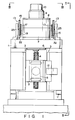
- Fig. 1 is a schematic elevation of the table equipment according to an embodiment of this invention;
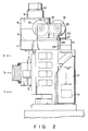
- Fig. 2 is a schematic side view as seen in the direction of the line II-II of Fig. 1;
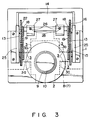
- Fig. 3 is a schematic plan view as seen in the direction of the line III-III of Fig. 1; and
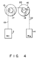
- Fig. 4 is a diagram to explain the principle of the force applying means.
- As shown in Figs. 1 and 2, the table equipment according to an embodiment of this invention has frame 1 and movable table 2 is mounted to frame 1 in such a way that movable table 2 can move in the vertical direction.
- As illustrated in Fig. 3, this movable table 2 is guided by
vertical guide 3 constututed by a hydrostatic bearing in this embodiment. The hydrostatic bearing constitutingguide 3 has, between the guideway of frame 1 and the slideway of table 2, a pocket into which a pressure fluid is supplied from a pressure fluid source (not shown) and thereby movable table 2 is moved vertically.Pocket 3a of this hydrostatic bearing is sealed liquid-tightly. - Table 2 is drivingly connected through connecting means to the driving power source.
- Referring to Fig. 1, the connecting means has screw receiving
member 5 provided in Table 2 and driving screw 4 rotatably supported through screw bearing 6 by frame 1 and drivingly engaging withscrew receiving member 5. In this embodiment, driving screw 4 is directly connected with a DC motor which is the driving power source.Driving motor 7 is controlled by tachometer-generator 8. When drivingmotor 7 rotates as its operation is controlled by tachometer-generator 8, movable table 2 is moved vertically via driving screw 4 andscrew receiving member 5. - The angle of rotation of driving screw 4 is detected by
rotary encoder 10 connected to driving motor and tachometer-generator 8 throughcoupling 9. The rotating direction and angle of drivingmotor 7 are selected by a drive control system (not shown) such that movable table 2 can be moved to the raised position a, the mid-position b and the lowered position c shown in Fig. 2. The moved position of movable table 2 is detected bylinear encoder 12. The position information of movable table 2 detected bylinear encoder 12 is sent to the above-mentioned drive control system. - On the other hand, force applying means is connected to movable table 2, the said force applying means being used to apply to movable table 2 a force which, acting in the opposite direction, counterbalances the force effected by gravitational acceleration to the total weight of movable table 2 and other members mounted thereon, e.g.
screw holding member 5 and the article to be moved. - As shown in Figs. 1 and 3, there are provided in this
embodiment pulley mechanisms 13 provided at the upper left and upper right (as seen in Figs. 1 and 3) of frame 1,counterweights 14 and enlongated flexible members connecting movable table 2 withcounterweights 14. - As indicated in Fig. 4 schematically illustrating the principle of the force applying means,
pulley mechanisms 13 each have twostepped pulleys flexible wire 19, which is at one end connected to movable table 2, is wound around small-diameter portion 17 ofstepped pulley 15 shown at left in this figure and is fixed at the other end to small-diameter portion 18 of steppedpulley 16 at right. Therefore, steppedpulleys diameter portions first wire 19.Wire 22, which is at one end connected tocounterweight 14, is wound around large-diameter portion 20 ofstepped pulley 16 at right and is fixed at the other end to large-diameter portion 20. - These
pulleys plates 25 at the upper position of frame 1. - Referring to Fig. 2,
guide plates 27 are mounted to the top surface ofcounterweight 14. Eachguide plate 17 has formed therein aguide hole 26 into whichguide rod 28 is inserted andguide rod 28 is fixed to frame 1 and extends in the vertical direction. Therefore, whencounterweight 14 moves up and down, it is guided byguide rod 28, so that it is prevented from swinging. - If the total weight of whole movable table 2 including movable table 2 and the members mounted thereon is denoted by WT, the weight of
counterweight 14 by Ww, the radius of small-diameter pulley 18 by r1 and the radius of large-diameter pulley 20 by r2, the followings equality will be established inpulley mechanism 13.

Assuming, for example, the radius r1 of above-mentionedpulley 18 is 22mm and the radius r2 of large-diameter pulley 20 is 55mm, the following relation should hold between WT and Ww.

- Therefore, the weight Ww of
counterweight 14 can be made smaller than the total weight WT of movable table 2. - The table equipment described above can be used for machine tools such as milling machines. Also, it can be used for the table equipment of semiconductor wafer aligners. When this table equipment is used for a semi-conductor wafer aligner, mounting base 2a to mount a semiconductor wafer on movable table 2 is fixed in operative relation to an aligner.
- In the above-mentioned table equipment, the total weight of movable table 2 and the members mounted thereon is balanced through
pulley mechanism 13 withcounterweight 14. Therefore, when movable table moves upwards, through a load due to gravitational acceleration acts in its moving direction, the load is offset bycounterweight 14. When movable table 4 moves downwards, the load due to gravitational acceleration acts oncounterweight 14 but this load is offset by the load of movable table 2 moving in the opposite direction. Thus, when movable table 2 moves up or down, the effect of gravitational acceleration is always prevented. Hence, it is possible to move movable table 2 with a small force of the same magnitude both in raising and lowering it. - Therefore, according to this invention, it is not necessary to use an expensive, high-output driving motor to cope with a large load that occurs in raising movable table 2.
Counterweight 14 of a small size can be used. Accordingly, table equipment can be manufactured in a compact size and with low cost. Generally, when a motor with a capacity to generate a large driving force is used, the large inertia during operation and the low response velocity of this type of motor make it impossible to position the movable table at high speed. In contrast, in the table equipment according to the above-mentioned embodiment, a motor with a relatively small driving force can be used for the driving power source. Further, since the rise characteristics of the motor can be maintained equal even when its rotational direction is changed, the motor operation can be controlled easily and, therefore, the table equipment can be made to operate accurately and at high speed. - Further, because the force applying means of the above-mentioned table equipment has
pulley mechanism 13 and thispulley mechanism 13 balances the movable table withcounterweight 14 throughwires pulley mechanism 13 incorporates two steppedpulleys - As shown in Fig. 2, it is possible to install fluid chamber 1a containing a viscous fluid in frame 1 and let
counterweight 14 move in the fluid in the chamber. In this case, it is desirable to provide space betweencounterweight 14 and the internal walls of fluid chamber 1a to ensure that the fluid can move through the space whencounterweight 14 moves. Ifcounterweight 14 and fluid chamber 1a are formed as described, they serve as a fluid damper whencounterweight 14 moves in fluid chamber 1a, lessening or preventing the vibration ofcounterweight 14 andwire 22 whencounterweight 14 goes up and down and allowing movable table 2 to move smoothly. - In the above embodiment,
DC servo motor 7 is used as a driving power source, but a suitable driving power source such as a linear motor or an ordinary friction drive mechanism may be used. - Though movable table 2 of the above-described table equipment moves vertically, this invention is obviously applicable to table equipment having a movable table that moves tilted with respect to the vertical direction.
- It is to be understood that this invention is not limited to the above preferred embodiment but it is obvious that various changes and modifications may be made in the invention without departing from the scope of the appended claims.
Claims (7)
- Table equipment having a table for supporting an object, comprising:
a frame (1);
a table (2) for supporting an object, and movable relative to said frame (1);
a guide (3) for guiding said table (2) on said frame (1), in a line inclined to the horizontal plane,
a power source (7) mechanically coupled relative to the table (2) for driving said table (2) along said guide (3);
a counterweight (14) coupled to said table (2) to counterbalance the total weight of said table (2) and said object supported thereon; and
a transmission mechanism (15, 16, 19, 20, 1a) coupling said counterweight (14) and the table (2) for counterbalancing the total weight of said table (2) and said object supported thereon with the counterweight (14) lighter than said total weight,
characterized in that
said transmission mechanism (15, 16, 19, 20, 1a) includes a vertical fluid chamber (1a) mounted on said frame (1) for dampening the vibration generated by the transmission mechanism (15, 16, 19, 20, 1a) and containing a viscous fluid for movingly receiving said counterweight (14), thereby causing said table (2) to move smoothly. - The table equipment according to claim 1, characterized in that said force applying means includes an elongated flexible member (19, 20) and a pulley mechanism to guide said flexible member, said elongated flexible member having a first part (22) connected to said counterweight (14) and a second part (19) connected to said table (2).
- The table equipment according to claim 2, characterized in that said pulley mechanism (13) comprises a pulley (15, 16) having a large-diameter portion (20) around which said first part (22) is wound, and small-diameter portion (17, 18) around which said second part (19) is wound, said large-diameter portion and small-diameter portion being rotable together will each other.
- The table equipment according to claim 3, characterized in that said frame (1) has a guide rod (28) provided extending in the vertical direction for guiding said counterweight (14), and said counterweight (14) has a plate member (27) slidable on said guide rod (28).
- The table equipment according to any one of claims 1 to 4, characterized in that said fluid chamber (1a) is formed in dimensions such that there is space around said counterweight through which the viscous fluid flows.
- The table equipment according to any one of claims 1 to 5, characterized in that said movable table (2) can move in a horizontal plane.
- The table equipment according to claim 6, characterized in that said frame (1) is supported movably on a horizontal table.
Applications Claiming Priority (2)
| Application Number | Priority Date | Filing Date | Title |
|---|---|---|---|
| JP21214/88 | 1988-02-02 | ||
| JP63021214A JPH01199740A (en) | 1988-02-02 | 1988-02-02 | Table device |
Publications (3)
| Publication Number | Publication Date |
|---|---|
| EP0326859A2 EP0326859A2 (en) | 1989-08-09 |
| EP0326859A3 EP0326859A3 (en) | 1990-07-11 |
| EP0326859B1 true EP0326859B1 (en) | 1993-03-31 |
Family
ID=12048751
Family Applications (1)
| Application Number | Title | Priority Date | Filing Date |
|---|---|---|---|
| EP89100820A Expired - Lifetime EP0326859B1 (en) | 1988-02-02 | 1989-01-18 | Table equipment |
Country Status (5)
| Country | Link |
|---|---|
| US (1) | US4958815A (en) |
| EP (1) | EP0326859B1 (en) |
| JP (1) | JPH01199740A (en) |
| KR (1) | KR930004838B1 (en) |
| DE (1) | DE68905624T2 (en) |
Families Citing this family (5)
| Publication number | Priority date | Publication date | Assignee | Title |
|---|---|---|---|---|
| US5788018A (en) * | 1997-02-07 | 1998-08-04 | Otis Elevator Company | Traction elevators with adjustable traction sheave loading, with or without counterweights |
| SE515304C2 (en) * | 1999-11-08 | 2001-07-09 | Hydropulsor Ab | Easily mountable and removable machine |
| CN100418681C (en) * | 2006-10-25 | 2008-09-17 | 四川东风电机厂有限公司 | Pulley drive type inclined vertical trepanation drill and using method thereof |
| CN111795664B (en) * | 2020-07-23 | 2025-04-08 | 江苏立导科技有限公司 | Measuring device and curved surface workpiece measuring system |
| CN114535953B (en) * | 2022-02-25 | 2023-09-15 | 安徽耀达电机股份有限公司 | Rotor lifting device for motor assembly |
Family Cites Families (19)
| Publication number | Priority date | Publication date | Assignee | Title |
|---|---|---|---|---|
| US359437A (en) * | 1887-03-15 | Eldeidge m | ||
| US224862A (en) * | 1880-02-24 | Water-elevator | ||
| DE633122C (en) * | 1935-07-21 | 1936-07-20 | Raboma Maschinenfabrik Hermann | Device for counterbalancing machine parts that can be moved vertically by means of a rack and pinion |
| CH203756A (en) * | 1937-01-14 | 1939-03-31 | Deckel Fa Friedrich | Method for changing the size of the output force, which remains constant during operation, in devices with a deforming element having a helical part. |
| DE1180957B (en) * | 1957-08-21 | 1964-11-05 | Dresden Feinmess | Precision length part and measuring machine |
| US3495798A (en) * | 1967-12-09 | 1970-02-17 | Innocenti Soc Generale | Safety device for hanging counterweight |
| JPS5229048A (en) * | 1975-08-28 | 1977-03-04 | Mitsubishi Electric Corp | Lateral elevator |
| US4179947A (en) * | 1977-08-15 | 1979-12-25 | James Robert G | Counterbalanced pumping system |
| ATE3618T1 (en) * | 1979-12-04 | 1983-06-15 | Oerlikon Buehrle Ag | DEVICE FOR POSITIONING A WORKPIECE. |
| FR2494615A1 (en) * | 1980-11-24 | 1982-05-28 | Line Sa | DEVICE FOR BALANCING A MACHINING HEAD MOVING ON A MILLING ROPE AT A SINGLE AMOUNT |
| DE3108934C1 (en) * | 1981-03-10 | 1983-01-27 | Scharmann GmbH & Co, 4050 Mönchengladbach | Horizontal drilling and milling device with a headstock moved up and down on guides |
| NL8102616A (en) * | 1981-05-29 | 1982-12-16 | Philips Nv | GAMMATOMOGRAPH WITH PARALLELOGRAM SUSPENSION. |
| EP0068929A3 (en) * | 1981-06-10 | 1983-10-19 | Thomson-Csf | Device for balancing a vertically shiftable element, in particular a telescopic x-ray tube support |
| JPS6268210A (en) * | 1985-09-19 | 1987-03-28 | Toshiba Corp | Vertical type moving table device |
| JPS6268209A (en) * | 1985-09-19 | 1987-03-28 | Toshiba Corp | Vertical type moving table device |
| JP2510978B2 (en) * | 1985-09-19 | 1996-06-26 | 株式会社東芝 | Vertical movement table device |
| JPS6268208A (en) * | 1985-09-19 | 1987-03-28 | Toshiba Corp | Vertical type moving table device |
| JPS62157708A (en) * | 1985-12-27 | 1987-07-13 | Miki Puurii Kk | Vibration absorber of milling machine |
| US4835871A (en) * | 1986-10-31 | 1989-06-06 | Brown & Sharpe Manufacturing Co. | Counterweight for coordinate measuring machine |
-
1988
- 1988-02-02 JP JP63021214A patent/JPH01199740A/en active Granted
-
1989
- 1989-01-18 DE DE8989100820T patent/DE68905624T2/en not_active Expired - Fee Related
- 1989-01-18 EP EP89100820A patent/EP0326859B1/en not_active Expired - Lifetime
- 1989-01-23 US US07/300,596 patent/US4958815A/en not_active Expired - Fee Related
- 1989-01-31 KR KR1019890001041A patent/KR930004838B1/en not_active Expired - Fee Related
Also Published As
| Publication number | Publication date |
|---|---|
| DE68905624D1 (en) | 1993-05-06 |
| US4958815A (en) | 1990-09-25 |
| EP0326859A3 (en) | 1990-07-11 |
| JPH01199740A (en) | 1989-08-11 |
| JPH0523891B2 (en) | 1993-04-06 |
| DE68905624T2 (en) | 1993-07-29 |
| KR890012747A (en) | 1989-09-19 |
| KR930004838B1 (en) | 1993-06-09 |
| EP0326859A2 (en) | 1989-08-09 |
Similar Documents
| Publication | Publication Date | Title |
|---|---|---|
| US4909701A (en) | Articulated arm transfer device | |
| US4964221A (en) | Counterbalanced coordinate-measuring instrument | |
| US4666366A (en) | Articulated arm transfer device | |
| CA1231357A (en) | Articulated arm transfer device | |
| US5518550A (en) | Stage apparatus for an exposure apparatus including a contant tension spring for canceling out a gravitational force of a movable stage by a tensile force | |
| KR101677020B1 (en) | Torch angle adjustment equipment and Cutting device having the same | |
| US9789578B2 (en) | Counterforce mechanism and methods of operation thereof | |
| US5587637A (en) | Robot arm device capable of conveying an article in circumferential and radial directions | |
| US6766996B1 (en) | Manipulator | |
| US4958815A (en) | Table equipment | |
| CN105817776A (en) | Laser processing machine with weight compensation | |
| US6398098B1 (en) | Wire bonding head involving minimized tip skid | |
| JPH04372318A (en) | X, Y, Z drive device | |
| US5717138A (en) | Arrangement for driving a measuring spindle of a balancing machine | |
| EP0386590A1 (en) | A device for counter-balancing the weight and moment induced in operation by the moving head of a machine tool | |
| US4446628A (en) | Device for determining angle of inclination of ship | |
| ES2200993T3 (en) | GEMELA RECTIFIER. | |
| JPH052309Y2 (en) | ||
| US20040223824A1 (en) | Machine with X-axis double speed mechanism | |
| KR102401305B1 (en) | Single type scribe head device | |
| CN115683555B (en) | Center of gravity adaptive adjustment device | |
| JP3014003B2 (en) | Vertical XY stage | |
| CN215580841U (en) | Motor rotor dynamic balance supporting device | |
| JPH0128955Y2 (en) | ||
| CA1322050C (en) | Magnetic disc unit |
Legal Events
| Date | Code | Title | Description |
|---|---|---|---|
| PUAI | Public reference made under article 153(3) epc to a published international application that has entered the european phase |
Free format text: ORIGINAL CODE: 0009012 |
|
| 17P | Request for examination filed |
Effective date: 19890215 |
|
| AK | Designated contracting states |
Kind code of ref document: A2 Designated state(s): CH DE GB LI |
|
| PUAL | Search report despatched |
Free format text: ORIGINAL CODE: 0009013 |
|
| RHK1 | Main classification (correction) |
Ipc: B23Q 11/00 |
|
| AK | Designated contracting states |
Kind code of ref document: A3 Designated state(s): CH DE GB LI |
|
| 17Q | First examination report despatched |
Effective date: 19910814 |
|
| GRAA | (expected) grant |
Free format text: ORIGINAL CODE: 0009210 |
|
| AK | Designated contracting states |
Kind code of ref document: B1 Designated state(s): CH DE GB LI |
|
| REF | Corresponds to: |
Ref document number: 68905624 Country of ref document: DE Date of ref document: 19930506 |
|
| PLBE | No opposition filed within time limit |
Free format text: ORIGINAL CODE: 0009261 |
|
| STAA | Information on the status of an ep patent application or granted ep patent |
Free format text: STATUS: NO OPPOSITION FILED WITHIN TIME LIMIT |
|
| 26N | No opposition filed | ||
| PGFP | Annual fee paid to national office [announced via postgrant information from national office to epo] |
Ref country code: GB Payment date: 19960109 Year of fee payment: 8 |
|
| PGFP | Annual fee paid to national office [announced via postgrant information from national office to epo] |
Ref country code: DE Payment date: 19960126 Year of fee payment: 8 |
|
| PGFP | Annual fee paid to national office [announced via postgrant information from national office to epo] |
Ref country code: CH Payment date: 19960212 Year of fee payment: 8 |
|
| PG25 | Lapsed in a contracting state [announced via postgrant information from national office to epo] |
Ref country code: GB Effective date: 19970118 |
|
| PG25 | Lapsed in a contracting state [announced via postgrant information from national office to epo] |
Ref country code: LI Effective date: 19970131 Ref country code: CH Effective date: 19970131 |
|
| GBPC | Gb: european patent ceased through non-payment of renewal fee |
Effective date: 19970118 |
|
| REG | Reference to a national code |
Ref country code: CH Ref legal event code: PL |
|
| PG25 | Lapsed in a contracting state [announced via postgrant information from national office to epo] |
Ref country code: DE Effective date: 19971001 |