EP0325280A1 - Flexible suction cup for delicate objects - Google Patents
Flexible suction cup for delicate objects Download PDFInfo
- Publication number
- EP0325280A1 EP0325280A1 EP89100979A EP89100979A EP0325280A1 EP 0325280 A1 EP0325280 A1 EP 0325280A1 EP 89100979 A EP89100979 A EP 89100979A EP 89100979 A EP89100979 A EP 89100979A EP 0325280 A1 EP0325280 A1 EP 0325280A1
- Authority
- EP
- European Patent Office
- Prior art keywords
- suction
- suction plate
- plate according
- vacuum
- channel
- Prior art date
- Legal status (The legal status is an assumption and is not a legal conclusion. Google has not performed a legal analysis and makes no representation as to the accuracy of the status listed.)
- Withdrawn
Links
Images


Classifications
-
- B—PERFORMING OPERATIONS; TRANSPORTING
- B66—HOISTING; LIFTING; HAULING
- B66C—CRANES; LOAD-ENGAGING ELEMENTS OR DEVICES FOR CRANES, CAPSTANS, WINCHES, OR TACKLES
- B66C1/00—Load-engaging elements or devices attached to lifting or lowering gear of cranes or adapted for connection therewith for transmitting lifting forces to articles or groups of articles
- B66C1/02—Load-engaging elements or devices attached to lifting or lowering gear of cranes or adapted for connection therewith for transmitting lifting forces to articles or groups of articles by suction means
- B66C1/0231—Special lip configurations
-
- B—PERFORMING OPERATIONS; TRANSPORTING
- B65—CONVEYING; PACKING; STORING; HANDLING THIN OR FILAMENTARY MATERIAL
- B65G—TRANSPORT OR STORAGE DEVICES, e.g. CONVEYORS FOR LOADING OR TIPPING, SHOP CONVEYOR SYSTEMS OR PNEUMATIC TUBE CONVEYORS
- B65G47/00—Article or material-handling devices associated with conveyors; Methods employing such devices
- B65G47/74—Feeding, transfer, or discharging devices of particular kinds or types
- B65G47/90—Devices for picking-up and depositing articles or materials
- B65G47/91—Devices for picking-up and depositing articles or materials incorporating pneumatic, e.g. suction, grippers
-
- B—PERFORMING OPERATIONS; TRANSPORTING
- B66—HOISTING; LIFTING; HAULING
- B66C—CRANES; LOAD-ENGAGING ELEMENTS OR DEVICES FOR CRANES, CAPSTANS, WINCHES, OR TACKLES
- B66C1/00—Load-engaging elements or devices attached to lifting or lowering gear of cranes or adapted for connection therewith for transmitting lifting forces to articles or groups of articles
- B66C1/02—Load-engaging elements or devices attached to lifting or lowering gear of cranes or adapted for connection therewith for transmitting lifting forces to articles or groups of articles by suction means
- B66C1/0212—Circular shape
-
- B—PERFORMING OPERATIONS; TRANSPORTING
- B66—HOISTING; LIFTING; HAULING
- B66C—CRANES; LOAD-ENGAGING ELEMENTS OR DEVICES FOR CRANES, CAPSTANS, WINCHES, OR TACKLES
- B66C1/00—Load-engaging elements or devices attached to lifting or lowering gear of cranes or adapted for connection therewith for transmitting lifting forces to articles or groups of articles
- B66C1/02—Load-engaging elements or devices attached to lifting or lowering gear of cranes or adapted for connection therewith for transmitting lifting forces to articles or groups of articles by suction means
- B66C1/0287—Other shapes, e.g. triangular or oval
-
- Y—GENERAL TAGGING OF NEW TECHNOLOGICAL DEVELOPMENTS; GENERAL TAGGING OF CROSS-SECTIONAL TECHNOLOGIES SPANNING OVER SEVERAL SECTIONS OF THE IPC; TECHNICAL SUBJECTS COVERED BY FORMER USPC CROSS-REFERENCE ART COLLECTIONS [XRACs] AND DIGESTS
- Y10—TECHNICAL SUBJECTS COVERED BY FORMER USPC
- Y10S—TECHNICAL SUBJECTS COVERED BY FORMER USPC CROSS-REFERENCE ART COLLECTIONS [XRACs] AND DIGESTS
- Y10S209/00—Classifying, separating, and assorting solids
- Y10S209/905—Feeder conveyor holding item by suction
-
- Y—GENERAL TAGGING OF NEW TECHNOLOGICAL DEVELOPMENTS; GENERAL TAGGING OF CROSS-SECTIONAL TECHNOLOGIES SPANNING OVER SEVERAL SECTIONS OF THE IPC; TECHNICAL SUBJECTS COVERED BY FORMER USPC CROSS-REFERENCE ART COLLECTIONS [XRACs] AND DIGESTS
- Y10—TECHNICAL SUBJECTS COVERED BY FORMER USPC
- Y10T—TECHNICAL SUBJECTS COVERED BY FORMER US CLASSIFICATION
- Y10T428/00—Stock material or miscellaneous articles
- Y10T428/24—Structurally defined web or sheet [e.g., overall dimension, etc.]
- Y10T428/24273—Structurally defined web or sheet [e.g., overall dimension, etc.] including aperture
- Y10T428/24298—Noncircular aperture [e.g., slit, diamond, rectangular, etc.]
- Y10T428/24314—Slit or elongated
-
- Y—GENERAL TAGGING OF NEW TECHNOLOGICAL DEVELOPMENTS; GENERAL TAGGING OF CROSS-SECTIONAL TECHNOLOGIES SPANNING OVER SEVERAL SECTIONS OF THE IPC; TECHNICAL SUBJECTS COVERED BY FORMER USPC CROSS-REFERENCE ART COLLECTIONS [XRACs] AND DIGESTS
- Y10—TECHNICAL SUBJECTS COVERED BY FORMER USPC
- Y10T—TECHNICAL SUBJECTS COVERED BY FORMER US CLASSIFICATION
- Y10T428/00—Stock material or miscellaneous articles
- Y10T428/24—Structurally defined web or sheet [e.g., overall dimension, etc.]
- Y10T428/24273—Structurally defined web or sheet [e.g., overall dimension, etc.] including aperture
- Y10T428/24322—Composite web or sheet
Definitions
- the invention relates to elastic suction plates for vacuum systems.
- Suction cups or suction plates made of elastically deformable material, which are connected to a vacuum system with the aid of rigid, mostly metallic parts, are particularly suitable for lifting and transporting compact objects with an essentially flat surface. If such a suction plate rests on the object to be transported or lifted and a negative pressure is generated in the cavity between the suction plate and the object, considerable forces can be transmitted. In particular, it is possible in this way to lift relatively heavy objects and to transport them to a desired place, where the objects are deposited by releasing the negative pressure.
- the suction cup has a resilient lip along its outer contour ensures a good seal between the suction cup and the object to be lifted.
- a suction cup with a metallic connector and an elastomer body attached to it is known.
- This elastomer body has a total of three sealing lips of different diameters arranged concentrically to one another.
- a suction plate for concrete composite blocks which has a vacuum connection piece and an elastomer body attached to it.
- the sealing lip of this elastomer body follows the outer contour of the stones to be transported.
- This known suction plate lies with its circumferential sealing lip and with a large number of rubber knobs which are formed in the inner surface of the known suction plate on the surface of the stones to be transported. These rubber knobs serve to support the suction plate in many places on the stone surface.
- the surface area of the suction plate occupied by these rubber knobs must not be too large, since the negative pressure is only effective in the cavities between the circumferential sealing lip and the knobs.
- the distances between the individual rubber knobs should be relatively small, because otherwise the sensitive "fresh” stone surface will be slightly damaged.
- Such damage can consist, for example, of "tearing out” concrete parts, especially in the area of the vacuum connection points; “Blistering” between and under the knobs; “Sliding marks” due to lateral displacement of the circumferential sealing lip when sucking in.
- the invention has for its object to provide a vacuum suction plate made of elastically deformable material for lifting and transporting sensitive objects, especially freshly made concrete blocks of the type specified in the preamble of claim 1, that there is a multi-stage sealing effect and the risk of tearing out of particles from the surface of the object to be lifted and transported is significantly reduced.
- the invention aims to counter the formation of harmful air currents when evacuating the suction space, since excessive air currents can cause damage to the surfaces of the object to be transported.
- the specific surface load of the objects to be transported should also be kept low, and yet a good support of the suction plate on the surface of the object to be transported should be ensured.
- the suction plates according to the invention are distinguished by the following features: -
- the suction chamber is divided into numerous suction chambers, each of which forms a lockable suction chamber;
- Each of the chambers is connected to at least one connection to the suction connection, ie to the vacuum source, a main connection channel being expediently provided between a plurality of vacuum connection points because of the pressure or flow compensation;
- the air connections reaching from the vacuum connection to the individual suction spaces are branched in such a way that their free flow cross-section is adapted to the number of suction chambers or connections that are to be supplied by the respective air connection.
- each of the connecting channels has the largest possible length dimension; -
- Each connecting channel between the individual suction spaces and the main vacuum connection has at least one, but preferably several strong changes in direction in its course;
- the connecting channels preferably have a rectangular cross-section, the dimensions in the width direction and in the height direction being chosen significantly different from one another;
- the sealing lip has a great flexibility perpendicular to the surface of the transporting object (stone surface) with such a stable design of the lip base that the lip is under vacuum not shifted sideways on the stone surface; -
- the contour of this sealing lip follows an annular chamber in the form of a circumferential depression, which, however, cannot be connected to the vacuum system;
- Within the foot of the sealing lip and the outer contour essentially following a circumferential suction space is provided, which is advantageously divided into a plurality of suction chambers, each of which suction chamber has at least one connecting channel to the vacuum connection; -
- the technical progress achievable with the aid of the invention results primarily from the fact that - A multi-stage sealing effect is achieved; - There is no harmful air flow at any point on the surface of the object to be transported; - The formation of harmful air currents is counteracted by the strong changes in direction of the flow connection channels, so that no particles from the Surface of the objects to be transported (grains of sand in the case of freshly made concrete blocks) are torn out; - In the locations of the change in direction in the connecting channels, entrained foreign particles may still be caught; - A blockage of the connecting channels by the possibly entrained particles is prevented, since the connecting channels have rectangular cross sections, whereas the particles generally have a round shape; - The flanks of the suction chambers or their webs are inclined at angles of significantly less than 90 ° relative to the stone surface, which makes undesired deposits and blockages difficult and cleaning work easier; - The suction plate according to the invention is supported on a multiplicity of comparatively large-area webs which the individual suction chambers take
- the required vacuum connection piece which is made of metal or plastic, can be added subsequently without permanent mechanical connection to the elastomer suction cup.
- the seal between the elastomer suction cup and the vacuum connection part takes place without any special measures simply by connecting the connection piece to the vacuum system.
- the undercut area in the elastomer body serves to accommodate the vacuum connection piece. An additional sealing effect occurs automatically when the negative pressure is applied.
- the suction plate according to the invention can be manufactured extremely inexpensively despite its very special shape.
- the known suction cup shown in Fig. 1 according to the Swedish utility model GM 80-0078 consists of a vacuum connector 1 made of metal and a vulcanized or otherwise attached airtight Elastomer body 2. This has a total of three circular concentric sealing lips 3, 4 and 5, which means that the suction space is sealed with a high degree of certainty. In addition, because of the two inner sealing lips 4 and 5, each of which has a smaller diameter, curved surfaces can be better sealed.
- Fig. 2 shows a known suction plate for concrete composite blocks, with a metal connector 6 and an airtight connected elastomer body 7.
- This body 7 has a sealing lip which is adapted to the substantially rectangular outer contour of the stones, this sealing lip everywhere is dimensioned somewhat smaller than the flat stone surface.
- numerous rubber knobs 9 are provided in the interior of the suction space, with which the suction plate is supported on the stones to be lifted and transported.
- a multiplicity of interconnected suction spaces 10 is formed in the interior of the suction space between the suction nubs 8.
- FIGS. 3 to 9, which explain the invention, are described in more detail below.
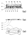
- Fig. 3 shows a section through an elastomer body 11 along the line III-III in Fig. 6.
- the elastomer body 11 comprises a circumferential sealing lip 12, an outer ring web 13, an inner ring web 14 and a plurality of longitudinal webs 15 and transverse webs 16 (Fig 6).
- an outer ring channel 17, which, however, cannot be connected to a vacuum source an inner ring channel 18, which is preferably divided by transverse webs 16 and can be connected to the vacuum source, not shown, and numerous elongate suction chambers 19 are formed.
- these elongate suction chambers 19 run parallel to one another within the inner ring channel 18.
- These suction chambers 19, like the ring channel 18, have inclined flanks 20 of low steepness. For example the preferred angle of inclination of these flanks is 45 ° with respect to the stone surface.
- These connecting channels 21 are divided into a first vertically running section 21a and a second section 21b, which runs horizontally, as best can be seen in Fig. 7.
- the boundary plane between the horizontally running section 21b and the vertically running section 21a of the connecting channels 21 is given by the parting plane of a vulcanization mold, not shown in FIG.
- At least one connecting channel 22 extends from each suction chamber 19 and is divided into a vertically running section 22a and a horizontally running section 22b.
- the vertically running connecting channel sections 21a and 22a are best shown in FIGS. 3 and 6, whereas the horizontally running connecting channel sections 21b and 22b are best seen in FIGS. 3 and 7.
- the boundary plane between the vertically running sections 22a and the horizontally running sections 22b runs through the parting plane 23 of the vulcanizing mold, not shown, in FIG. 3.
- the undercut area 25 is formed by a relatively thick circumferential, elastic lip 24 in the elastomer body 11. If the vacuum connection piece 26 shown in FIG. 4 is buttoned into the undercut area 25, the circumferential lip 24 forms a seal. Two threaded connections 28 are formed in the connecting piece 26, with the help of which the connector can be connected to a vacuum source, not shown. If a vacuum is built up in the suction plate according to the invention, a rigid, strip-like projection 29 (FIG. 5) of the connecting piece 26 provides both guidance and a limitation against excessive compression of the elastic lip 24.
- the above-mentioned parting plane 23 runs through the full elastomer cross section, as shown in FIG. 3.
- This parting plane essentially coincides with the bottom of the horizontally extending connecting channels 22b. Since these horizontal connecting channels have a depth of 2 to 6 mm, preferably of approximately 4 mm, based on the surface of the elastomer body 11 shown in FIGS. 7 and 9, the mold parting plane 23 runs at a depth of 2 to 6 mm, preferably about 4 mm, below the surface of the elastomer body. It goes without saying that the surface of the elastomer body in question is the surface forming the lower end of the undercut region 25 in FIG. 3.
- Fig. 6 shows a bottom view of a first embodiment of the suction plate according to the invention.
- Fig. 7 shows a plan view of the suction plate shown in Fig. 6, but in Fig. 7 the circumferential lip 24 has been cut away. 7 is thus specifically a section through the elastomer body 11, the section plane running at the level of the undercut region 25.
- the first embodiment according to FIGS. 6 and 7 has two vacuum connection points 30 which are connected to one another by a horizontally extending main channel 31 formed in the surface of the elastomer body. As shown in the drawing, the main channel 31 extends beyond the two connection points 30. All horizontally extending connecting channel sections 21b and 22b branch off from this main channel.
- the vertical connecting channel sections mün the vertical connecting channel sections 21a and 22a, which extend perpendicular to these channels, as best shown in FIGS. 6 and 7.
- the vertical connecting duct sections preferably open into the horizontally running sections 21b and 22b as far as possible from the main duct 31.
- the locations in which the vertically running duct sections open into the horizontally running duct sections are places of a strong change of direction for the air flows sucked out of the suction space.
- All sections of the connecting channels, including the main channel, are created during vulcanization.
- one half of the vulcanization form has strip-like projections.
- pin-like projections are provided in the other half of the vulcanization mold. The strip-like projections and the pin-like projections of the two mold halves touch one another in the mold parting plane 23 (FIG. 3).
- a cross-section which is as rectangular as possible is provided for the connecting channels, insofar as this can be achieved in terms of molding technology with little effort.
- FIGS. 6 and 7 corresponds essentially to the shape of a concrete block in terms of its outer shape, as does the conventional suction plate shown in FIG. 2.
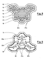
- Figures 8 and 9 show a differently designed embodiment of the invention, the shape of which is pronounced of a three-leaf clover.
- the bottom view of the suction plate lower surface shown in FIG. 8 shows, in the manner described with reference to the first embodiment, a multiplicity of vertically running connecting channels 21a and 22a, which, by means of horizontally running connecting channel sections 21b, 22b and connect with the help of a horizontally running main channel 33 to a vacuum source, not shown.
- the embodiment according to FIGS. 8 and 9 has a three-armed, star-shaped, horizontally running main channel 33, in the vicinity of the end sections of which a vacuum connection point 32 is formed.
- the horizontal sections 21b and 22b of the connecting channels branch off from this star-shaped main channel 33, as described with reference to FIGS. 6 and 7.
- the parting plane 23 shown in FIG. 3 forms the boundary plane between the horizontally running channels or channel sections 21b, 22b and 33 and the vertically running channel sections 21a and 22a.
- the elongated suction chambers 19 are provided with at least one vertical channel section 22a, which is connected to the vacuum source, not shown. Only the shortest of the suction chambers 19 have only one such flow connection with the vacuum source. All other suction chambers 19 are provided with two flow connections to the vacuum source in the form of the vertically extending connecting channel sections, which after a strong change in direction change into the horizontally running channel sections or the main channels and from there via the vacuum connection points 30 (FIG. 7) and 32 (Fig. 9) are connected to a vacuum source. According to FIG. 8, the suction spaces formed with the aid of the crosspieces 16 in the annular channel 18 are provided with only a single connecting channel 21a.
- the horizontally running connecting channel sections 21b, 22b are arranged as far apart as possible in order to supply the entire area of the suction space as evenly as possible.
- the horizontally extending duct sections branching off from the main ducts 31 and 33 are oriented in such a way that, in addition to the 90 ° change in direction already mentioned, there are further changes in direction for the air streams flowing through the ducts when changing from a vertical duct section to a horizontal duct section.
- the mentioned further direction changes also take place when flowing through the horizontal channels in the region of the mold parting plane 23.
- none of the vertical connecting duct sections opens directly onto one of the main ducts 31 or 32. In this way it is avoided that one which is not characterized by a change in direction Flow connection between a main channel and the surface of an object to be transported, such as a fresh concrete block surface. Due to the changes in direction in their flow channels, the air masses extracted from the suction space experience a reduction in their speed, so that the probability is reduced that particles are entrained, for example, by a stone surface.
- the total suction space present in the suction plate according to the invention within the circumferential sealing lip is divided into a large number of individual suction chambers which, because of their webs 15, 16, develop a suction effect independently of one another.
- the suction plate according to the invention provides a practically “crossing-free” air duct in different planes, with no complicated measures, such as undercuts, being required in the vulcanization molds to produce the air channels in the elastomer body of the suction plate according to the invention.
- the width of the suction chambers 19 is significantly smaller than the length of these suction chambers and is preferably less than 20 mm. The same applies to the suction chambers formed in the annular channel 18 by means of the crosspieces 16.
- suction cups according to the invention show signs of wear on the elastomer body, this can be easily replaced with a new elastomer body.
- the vacuum connector 26 does not need to be replaced.
Abstract
Description
Die Erfindung bezieht sich auf elastische Saugteller für Vakuumsysteme. Saugnäpfe bzw. Saugteller aus elastisch verformbarem Werkstoff, die mit Hilfe von starren, meist metallischen Teilen an ein Unterdrucksystem angeschlossen werden, eignen sich speziell zum Anheben und Transportieren kompakter Objekte mit im wesentlichen ebener Oberfläche. Wenn ein solcher Saugteller an dem zu transportierenden bzw. anzuhebenden Objekt anliegt und in dem Hohlraum zwischen dem Saugteller und dem Objekt ein Unterdruck erzeugt wird, so lassen sich erhebliche Kräfte übertragen. Insbesondere ist es auf diese Weise möglich, relativ schwere Objekte anzuheben und zu einem gewünschten Platz zu transportieren, wo die Objekte durch Aufheben des Unterdruckes abgesetzt werden.The invention relates to elastic suction plates for vacuum systems. Suction cups or suction plates made of elastically deformable material, which are connected to a vacuum system with the aid of rigid, mostly metallic parts, are particularly suitable for lifting and transporting compact objects with an essentially flat surface. If such a suction plate rests on the object to be transported or lifted and a negative pressure is generated in the cavity between the suction plate and the object, considerable forces can be transmitted. In particular, it is possible in this way to lift relatively heavy objects and to transport them to a desired place, where the objects are deposited by releasing the negative pressure.
Bei unempfindlichen Objekten treten hierbei keine besondere Probleme auf. Erforderlich ist lediglich, daß der Saugnapf entlang seiner Außenkontur eine nachgiebige Lippe besitzt, die eine gute Abdichtung zwischen dem Saugnapf und dem anzuhebenden Objekt gewährleistet.There are no particular problems with insensitive objects. All that is required is that the suction cup has a resilient lip along its outer contour ensures a good seal between the suction cup and the object to be lifted.
Schwierigkeiten ergeben sich aber, wenn empfindliche Objekte, insbesondere solche mit wenig widerstandsfähiger Oberfläche, durch Saugteller angehoben werden sollen. So ist es beispielsweise wünschenswert, "frische" Beton-Verbundsteine unmittelbar nach der Herstellung handhaben zu können, obgleich derartige frisch hergestellte Steine erst nach einigen Tagen eine hinreichend hohe Festigkeit aufweisen. Probleme treten insbesondere bei Verbundsteinen mit "Vorsatzbeton" auf, also bei Betonsteinen, die in ihrem oberen Bereich aus einer relativ dünnen, meist feinkörnigen Deckschicht bestehen, welche mit dem darunterliegenden "Kernbeton" nicht immer ganz oder noch nicht ganz homogen verbunden ist.Difficulties arise, however, when sensitive objects, in particular those with a surface that is not very resistant, are to be lifted by suction plates. For example, it is desirable to be able to handle "fresh" concrete composite blocks immediately after production, although such freshly produced stones only have a sufficiently high strength after a few days. Problems occur in particular with composite blocks with "facing concrete", that is to say with concrete blocks which consist in their upper area of a relatively thin, mostly fine-grained surface layer which is not always or not entirely homogeneously connected to the underlying "core concrete".
Aus dem schwedischen Gebrauchsmuster GM 80-0078 ist beispielsweise ein Saugnapf mit einem metallischen Anschlußstück und einem daran befestigten Elastomerkörper bekannt. Dieser Elastomerkörper besitzt insgesamt drei konzentrisch zueinander angeordnete Dichtlippen unterschiedlichen Durchmessers.From the Swedish utility model GM 80-0078, for example, a suction cup with a metallic connector and an elastomer body attached to it is known. This elastomer body has a total of three sealing lips of different diameters arranged concentrically to one another.
Es ist bereits ein Saugteller für Beton-Verbundsteine bekannt, der ein Unterdruck-Anschlußstück und einen daran befestigten Elastomer-Körper aufweist. Die Dichtlippe dieses Elastomerkörpers folgt der äußeren Kontur der zu transportierenden Steine. An der Oberfläche der zu transportierenden Steine liegt dieser bekannte Saugteller mit seiner umlaufenden Dichtlippe sowie mit einer Vielzahl von Gumminoppen an, die in der Innenoberfläche des bekannten Saugtellers ausgebildet sind. Diese Gumminoppen dienen dazu, den Saugteller an vielen Stellen auf der Steinoberfläche abzustützen. Die von diesen Gumminoppen eingenommene Oberfläche des Saugtellers darf nicht zu groß sein, da der Unterdruck lediglich in den Hohlräumen zwischen der umlaufenden Dichtlippe und den Noppen wirksam ist. Andererseits jedoch sollten die Abstände zwischen den einzelnen Gumminoppen relativ klein sein, da sonst die empfindliche "frische" Steinoberfläche leicht beschädigt wird. Solche Beschädigungen können beispielsweise bestehen in einem "Herausreißen" von Betonteilen, vor allem im Bereich der Unterdruck-Anschlußstellen; "Blasenbildung" zwischen den Noppen und unter diesen; "Schiebespuren" durch seitliche Verschiebung der umlaufenden Dichtlippe beim Ansaugen.A suction plate for concrete composite blocks is already known, which has a vacuum connection piece and an elastomer body attached to it. The sealing lip of this elastomer body follows the outer contour of the stones to be transported. This known suction plate lies with its circumferential sealing lip and with a large number of rubber knobs which are formed in the inner surface of the known suction plate on the surface of the stones to be transported. These rubber knobs serve to support the suction plate in many places on the stone surface. The surface area of the suction plate occupied by these rubber knobs must not be too large, since the negative pressure is only effective in the cavities between the circumferential sealing lip and the knobs. On the other hand, however, the distances between the individual rubber knobs should be relatively small, because otherwise the sensitive "fresh" stone surface will be slightly damaged. Such damage can consist, for example, of "tearing out" concrete parts, especially in the area of the vacuum connection points; "Blistering" between and under the knobs; "Sliding marks" due to lateral displacement of the circumferential sealing lip when sucking in.
Ferner besteht bei diesem bekannten Saugteller die Gefahr, daß bei Undichtigkeiten der erforderliche Unterdruck nicht in der benötigten Höhe aufgebracht werden kann, so daß nicht nur ein einzelner Stein, sondern eine ganze Steinlage nicht abgehoben und abtransportiert werden kann. In einem solchen Fall wird nicht nur eine beträchtliche Menge an Ausschuß produziert, sondern wird eine gravierende Störung des gesamten Betriebsablaufes hervorgerufen.Furthermore, in this known suction plate there is a risk that the necessary vacuum cannot be applied at the required height in the event of leaks, so that not only a single stone but an entire layer of stones cannot be lifted off and transported away. In such a case, not only is a considerable amount of rejects produced, but a serious disruption to the entire course of operations is brought about.
Der Erfindung liegt die Aufgabe zugrunde, einen Unterdruck-Saugteller aus elastisch verformbaren Werkstoff zum Anheben und Transportieren empfindlicher Objekte, insbesondere von frisch hergestellten Beton-Verbundsteinen der im Oberbebriff des Anspruchs 1 angegebenen Gattung so auszubilden, daß eine mehrstufige Dichtwirkung vorliegt und die Gefahr des Herausreißens von Teilchen aus der Oberfläche des anzuhebenden und zu transportierenden Objektes wesentlich herabgesetzt ist. Innerhalb dieser Aufgabe verfolgt die Erfindung das Ziel, der Bildung schädlicher Luftströmungen beim Evakuieren des Saugraumes zu begegnen, da zu starke Luftströmungen Schäden in den Oberflächen des zu transportierenden Objektes hervorrufen können. Auch soll die spezifische Oberflächenbelastung der zu transportierenden Objekte gering gehalten und doch eine gute Abstützung des Saugtellers auf der Oberfläche des zu transportierenden Objektes gewährleistet werden.The invention has for its object to provide a vacuum suction plate made of elastically deformable material for lifting and transporting sensitive objects, especially freshly made concrete blocks of the type specified in the preamble of
Diese Aufgabe wird bei der im Anspruch 1 angegebenen Erfindung durch die im kennzeichnenden Teil des Anspruchs 1 angegebenen Merkmale gelöst.This object is achieved in the invention specified in
Bevorzugte Ausführungsformen und weitere Ausgestaltungen der Erfindung sind in den Unteransprüchen beschrieben.Preferred embodiments and further refinements of the invention are described in the subclaims.
Die erfindungsgemäßen Saugteller zeichnen sich in ihren bevorzugten Ausführungsformen durch die folgenden Merkmale aus:
- Der Ansaugraum ist in zahlreiche Saugkammern unterteilt, die jede für sich einen abschließbaren Saugraum bilden;
- jede der Kammern ist mit wenigstens einer Verbindung zum Absauganschluß, d.h. zur Unterdruckquelle, verbunden, wobei zweckmäßigerweise wegen des Druck- bzw. Strömungsausgleiches ein Haupt-Verbindungskanal zwischen mehreren Unterdruck-Anschlußstellen vorgesehen ist;
- die von dem Unterdruckanschluß zu den einzelnen Saugräumen reichenden Luftverbindungen sind derart verästelt, daß deren freier Strömungsquerschnitt an die Anzahl der Saugkammern bzw. Anschlüsse angepaßt ist, die von der jeweiligen Luftverbindung zu versorgen sind. Ferner ist dafür Sorge getragen, daß jeder der Anschlußkanäle (Verbindungskanäle) eine möglichst große Längenabmessung aufweist;
- jeder Verbindungskanal zwischen den einzelnen Saugräumen und dem Haupt-Unterdruckanschluß weist in seinem Verlauf wenigstens eine, vorzugsweise jedoch mehrere starke Richtungsänderungen auf;
- die Verbindungskanäle besitzen vorzugsweise einen rechteckigen Querschnitt, wobei die Abmessungen in Breitenrichtung und in Höhenrichtung deutlich unterschiedlich voneinander gewählt sind;
- die Dichtlippe besitzt eine große Nachgiebigkeit senkrecht zur Oberfläche des transportierenden Objektes (Steinoberfläche) mit einer derart stabilen Ausbildung des Lippenfußes, daß sich die Lippe bei Vakuum-Beaufschlagung nicht seitlich auf der Steinoberfläche verschiebt;
- auf der Innenseite der eigentlichen Dichtlippe verläuft der Kontur dieser Dichtlippe folgend eine Ringkammer in Form einer umlaufenden Vertiefung, die jedoch nicht an das Unterdrucksystem anschließbar ist;
- innerhalb des Fußes der Dichtlippe und der Außenkontur im wesentlichen folgend ist ein umlaufender Saugraum vorgesehen, der vorteilhafterweise in eine Vielzahl von Saugkammern unterteilt ist, von welchen jede Saugkammer wenigstens einen Verbindungskanal zum Unterdruck-Anschluß besitzt;
- der im Inneren des vorstehend genannten umlaufenden Saugraums verbleibende Innenraum des gesamten Ansaugraums ist in eine Vielzahl, vorzugsweise länglich ausgebildeter Saugkammern unterteilt, welche jeweils mindestens einen Verbindungskanal zum Unterdruck-Anschluß besitzen;
- diese länglichen Saugkammern haben vorzugsweise eine Breite von weniger als 20 mm und ihre Begrenzungsstege haben einen Flankenwinkel von vorzugsweise etwa 45°, wobei die Auflagefläche der Stege, mit welchen sich dieselben auf der Oberfläche des zu transportierenden Objektes abstützen, vorzugsweise eine Breite von 1 bis 4 mm aufweisen.In their preferred embodiments, the suction plates according to the invention are distinguished by the following features:
- The suction chamber is divided into numerous suction chambers, each of which forms a lockable suction chamber;
- Each of the chambers is connected to at least one connection to the suction connection, ie to the vacuum source, a main connection channel being expediently provided between a plurality of vacuum connection points because of the pressure or flow compensation;
- The air connections reaching from the vacuum connection to the individual suction spaces are branched in such a way that their free flow cross-section is adapted to the number of suction chambers or connections that are to be supplied by the respective air connection. Care is also taken to ensure that each of the connecting channels (connecting channels) has the largest possible length dimension;
- Each connecting channel between the individual suction spaces and the main vacuum connection has at least one, but preferably several strong changes in direction in its course;
- The connecting channels preferably have a rectangular cross-section, the dimensions in the width direction and in the height direction being chosen significantly different from one another;
- The sealing lip has a great flexibility perpendicular to the surface of the transporting object (stone surface) with such a stable design of the lip base that the lip is under vacuum not shifted sideways on the stone surface;
- On the inside of the actual sealing lip, the contour of this sealing lip follows an annular chamber in the form of a circumferential depression, which, however, cannot be connected to the vacuum system;
- Within the foot of the sealing lip and the outer contour essentially following a circumferential suction space is provided, which is advantageously divided into a plurality of suction chambers, each of which suction chamber has at least one connecting channel to the vacuum connection;
- The interior of the entire suction space remaining inside the aforementioned circumferential suction space is divided into a plurality, preferably elongate suction chambers, each of which has at least one connecting channel for the vacuum connection;
- These elongated suction chambers preferably have a width of less than 20 mm and their boundary webs have a flank angle of preferably about 45 °, the bearing surface of the webs, with which they are supported on the surface of the object to be transported, preferably a width of 1 to 4 mm.
Der mit Hilfe der Erfindung erzielbare technische Fortschritt ergibt sich in erster Linie daraus, daß
- eine mehrstufige Dichtungswirkung erreicht wird;
- an keiner Stelle der Oberfläche des zu transportierenden Objektes ein schädlicher Luftstrom entsteht;
- der Ausbildung schädlicher Luftströme durch die starke Richtungsänderungen der Strömungs-Verbindungskanäle entgegengewirkt ist, so daß keine Partikel aus der Oberfläche des zu transportierenden Objekte (Sandkörner im Falle von frisch hergestellten Beton-Verbundsteinen) herausgerissen werden;
- in den Orten der Richtungsänderung in den Verbindungskanälen gegebenenfalls dennoch mitgerissene Fremdpartikel aufgefangen werden;
- eine Verstopfung der Verbindungskanäle durch die gegebenenfalls dennoch mitgerissene Partikel verhindert wird, da die Verbindungskanäle rechteckige Querschnitte besitzen, wohingegen die Partikel in der Regel eine runde Gestalt aufweisen;
- die Flanken der Saugkammern bzw. derer Stege in Winkeln von deutlich weniger als 90° relativ zur Steinoberfläche geneigt sind, wodurch unerwünschte Ablagerungen und Verstopfungen erschwert und Reinigungsarbeiten erleichtert werden;
- sich der erfindungsgemäße Saugteller auf eine Vielzahl von vergleichsweise großflächigen Stegen, welche die einzelnen Saugkammern voneinander erfolgen, abstützt, wodurch die spezifische Oberflächenbelastung auf der Oberfläche des zu transportierenden Objekte gering gehalten ist, aber dennoch die Gesamt-Ansaugfläche des Saugtellers recht groß ist;
- sich Objekte mit empfindlicher Oberfläche, wie frisch hergestellte Betonsteine, schonend ansaugen und transportieren lassen;
- trotz rauher oder poröser Oberfläche der Objekte, wie die rauhe, poröse Oberfläche von Betonsteinen, eine gute Dichtwirkung erreicht wird, und
- bei örtlicher Undichtigkeit, d.h. bei Undichtigkeit in einer oder mehreren Saugkammern, der Unterdruck im gesamten Saugraum nicht stark beeinträchtigt wird (vgl. Schotten bei Seeschiffen), sondern daß selbst bei örtlichen Undichtigkeiten ein hinreichend starker Unterdruck in den dicht gebliebenen Bereichen des Saugraumes erhalten bleibt, so daß Einzelsteine bzw. ganze Steinlagen erfolgreich angehoben und transportiert werden können.The technical progress achievable with the aid of the invention results primarily from the fact that
- A multi-stage sealing effect is achieved;
- There is no harmful air flow at any point on the surface of the object to be transported;
- The formation of harmful air currents is counteracted by the strong changes in direction of the flow connection channels, so that no particles from the Surface of the objects to be transported (grains of sand in the case of freshly made concrete blocks) are torn out;
- In the locations of the change in direction in the connecting channels, entrained foreign particles may still be caught;
- A blockage of the connecting channels by the possibly entrained particles is prevented, since the connecting channels have rectangular cross sections, whereas the particles generally have a round shape;
- The flanks of the suction chambers or their webs are inclined at angles of significantly less than 90 ° relative to the stone surface, which makes undesired deposits and blockages difficult and cleaning work easier;
- The suction plate according to the invention is supported on a multiplicity of comparatively large-area webs which the individual suction chambers take from one another, as a result of which the specific surface load on the surface of the objects to be transported is kept low, but the total suction area of the suction plate is nevertheless quite large;
- Objects with a sensitive surface, such as freshly made concrete blocks, can be gently sucked in and transported;
- despite the rough or porous surface of the objects, such as the rough, porous surface of concrete blocks, a good sealing effect is achieved, and
- In the event of local leakage, ie if there is a leak in one or more suction chambers, the negative pressure in the entire suction chamber is not significantly affected (cf. Bulkheads on seagoing ships), but that even with local leaks, a sufficiently strong negative pressure is maintained in the tightly sealed areas of the suction chamber so that individual stones or entire stone layers can be successfully lifted and transported.
Die erwähnten, absichtlich herbeigeführten starken Umlenkungen des Luftstroms in den Verbindungskanälen werden, ebenso wie die Formgebung aller Kammern und Stege usw. ausschließlich durch eine entsprechende Ausgestaltung der zur Herstellung des Elastomerkörpers benutzten Vulkanisationsform erreicht, insbesondere durch eine zweckmäßige Ortslage der Trennebene, welche die obere und die untere Formhälfte der Vulkanisationsform voneinander trennt. Die Formhälften sind auf einfache Weise so bearbeitet, daß nennenswerte nachträgliche Arbeiten an dem Elastomerkörper nicht nötig sind. Wird an dem Elastomerkörper ein hinterschnittener Bereich vorgesehen, so kann ein reines Gummiformteil als eigentlicher Saugnapf verwendet werden. Um diesen Saugnapf zu einem Saugteller zu komplettieren, kann das benötigte Unterdruck-Anschlußstück, welches aus Metall oder Kunststoff besteht, nachträglich ohne dauerhafte mechanische Verbindung mit dem Elastomer-Saugnapf hinzugefügt werden. Die Abdichtung zwischen dem Elastomer-Saugnapf und dem Unterdruck-Anschlußteil erfolgt ohne besondere weitere Maßnahmen allein durch den Anschluß des Anschlußstückes am Unterdrucksystem. Der hinterschnittene Bereich im Elastomerkörper dient zur Aufnahme des Unterdruck-Anschlußstückes. Eine zusätzliche Dichtwirkung stellt sich beim Aufbringen des Unterdruckes von selbst ein. Aus den vorstehend genannten Gründen läßt sich der erfindungsgemäße Saugteller trotz seiner sehr speziellen Formgebung äußerst preisgünstig herstellen.The aforementioned, deliberately induced strong deflections of the air flow in the connecting channels, as well as the shape of all chambers and webs, etc., are achieved exclusively by a corresponding configuration of the vulcanization mold used to produce the elastomer body, in particular by an appropriate location of the parting plane, which the upper and separates the lower mold half of the vulcanization mold. The mold halves are machined in a simple manner so that significant subsequent work on the elastomer body is not necessary. If an undercut area is provided on the elastomer body, a pure molded rubber part can be used as the actual suction cup. In order to complete this suction cup into a suction plate, the required vacuum connection piece, which is made of metal or plastic, can be added subsequently without permanent mechanical connection to the elastomer suction cup. The seal between the elastomer suction cup and the vacuum connection part takes place without any special measures simply by connecting the connection piece to the vacuum system. The undercut area in the elastomer body serves to accommodate the vacuum connection piece. An additional sealing effect occurs automatically when the negative pressure is applied. For the reasons mentioned above, the suction plate according to the invention can be manufactured extremely inexpensively despite its very special shape.
Die Erfindung wird im folgenden anhand von Ausführungsbeispielen unter Bezug auf die Zeichnung (Figuren 3 bis 9) näher beschrieben. In dieser zeigt:
- Fig. 1 einen Schnitt durch einen herkömmlichen Saugteller mit drei konzentrisch zueinander angeordneten Dichtlippen, wobei diese Dichtlippen unterschiedliche Durchmesser aufweisen und der Dichtteller außerdem ein anvulkanisiertes Unterdruck-Anschlußstück aufweist,
- Fig. 2 einen Schnitt durch einen anderen herkömmlichen Saugteller mit lediglich einer kontinuierlichen Dichtlippe sowie mit zahlreichen Noppen und einem anvulkanisierten Unterdruck-Anschlußstück in Form einer Metallplatte,
- Fig. 3 einen Schnitt durch den Elastomerkörper des Saugtellers nach der Erfindung entlang Linie III-III in Fig. 6,
- Fig. 4 einen Schnitt durch ein starres Unterdruck-Anschlußstück für den Saugteller gemäß Fig. 3,
- Fig. 5 eine Aufsicht auf das in Fig. 4 dargestellte Anschlußstück,
- Fig. 6 eine erste Ausführungsform eines Saugtellers in einer Unteransicht,
- Fig. 7 eine Aufsicht auf den in Fig. 5 dargestellten Saugteller, wobei das Anschlußstück weggeschnitten ist,
- Fig. 8 eine andere Ausführungsform des Saugtellers in einer Unteransicht und
- Fig. 9 eine Aufsicht auf den in Fig. 8 dargestellten Saugteller, wobei das Anschlußstück weggeschnitten ist.
- 1 shows a section through a conventional suction plate with three sealing lips arranged concentrically to one another, these sealing lips having different diameters and the sealing plate also having a vulcanized vacuum connection piece,
- 2 shows a section through another conventional suction plate with only one continuous sealing lip and with numerous knobs and a vulcanized vacuum connection piece in the form of a metal plate,
- 3 shows a section through the elastomer body of the suction plate according to the invention along line III-III in FIG. 6,
- 4 shows a section through a rigid vacuum connection piece for the suction plate according to FIG. 3,
- 5 is a plan view of the connector shown in FIG. 4,
- 6 shows a first embodiment of a suction plate in a bottom view,
- 7 is a plan view of the suction plate shown in FIG. 5, the connector being cut away,
- Fig. 8 shows another embodiment of the suction plate in a bottom view and
- Fig. 9 is a plan view of the suction plate shown in Fig. 8, wherein the connector is cut away.
Der in Fig. 1 dargestellte bekannte Saugnapf nach dem schwedischen Gebrauchsmuster GM 80-0078 besteht aus einem Unterdruck-Anschlußstück 1 aus Metall und einem daran anvulkanisierten oder in anderer Weise luftdicht befestigten Elastomerkörper 2. Dieser besitzt insgesamt drei kreisförmige konzentrische Dichtlippen 3, 4 und 5, wodurch mit hoher Sicherheit eine Abdichtung des Saugraumes erreicht wird. Außerdem können wegen der beiden inneren Dichtlippen 4 und 5, die jeweils einen kleineren Durchmesser aufweisen, gewölbte Oberflächen besser abgedichtet werden.The known suction cup shown in Fig. 1 according to the Swedish utility model GM 80-0078 consists of a
Fig. 2 zeigt einen bekannten Saugteller für Beton-Verbundsteine, mit einem aus Metall bestehenden Anschlußstück 6 und einen damit luftdicht verbundenen Elastomerkörper 7. Dieser Köper 7 besitzt eine Dichtlippe, welche der im wesentlichen rechteckigen äußeren Kontur der Steine angepaßt ist, wobei diese Dichtlippe überall etwas kleiner dimensioniert ist als die ebene Steinoberfläche. Im Inneren des Saugraums sind bei dem bekannten Saugteller zahlreiche Gumminoppen 9 vorgesehen, mit welcher sich der Saugteller auf den zu hebenden und zu transportierenden Steinen abstützt. Im Inneren des Saugraums ist zwischen den Saugnoppen 8 eine Vielzahl von miteinander verbundenen Saugräumen 10 ausgebildet.Fig. 2 shows a known suction plate for concrete composite blocks, with a metal connector 6 and an airtight
Im folgenden werden die die Erfindung erläuternden Figuren 3 bis 9 näher beschrieben.FIGS. 3 to 9, which explain the invention, are described in more detail below.
Fig. 3 zeigt einen Schnitt durch einen Elastomerkörper 11 entlang der Linie III-III in Fig. 6. Der Elastomerkörper 11 umfaßt eine umlaufende Dichtlippe 12, einen äußeren Ringsteg 13, einen inneren Ringsteg 14 sowie eine Vielzahl von Längsstegen 15 und Querstegen 16 (Fig. 6). Dadurch werden ein äußerer Ringkanal 17, der jedoch nicht an eine Unterdruckquelle anschließbar ist, ein vorzugsweise durch Querstege 16 geteilter innerer Ringkanal 18, der an die nicht dargestellte Unterdruckquelle anschließbar ist, sowie zahlreiche längliche Saugkammern 19 gebildet. Wie den Figuren 3 und 6 zu entnehmen, verlaufen diese längliche Saugkammern 19 parallel zueinander innerhalb des inneren Ringkanals 18. Diese Saugkammern 19 besitzen, ebenso wie der Ringkanal 18, geneigte Flanken 20 von geringer Steilheit. Beispielsweise beträgt der bevorzugte Neigungswinkel dieser Flanken 45° in bezug auf die Steinoberfläche. Vom Ringkanal 18 verlaufen in Richtung auf einen hinterschnittenen Bereich 25, welcher zur Aufnahme eines Unterdruck-Anschlußstückes 26 dient, Verbindungskanäle 21. Diese Verbindungskanäle 21 sind unterteilt in einen ersten vertikal verlaufenden Abschnitt 21a und einen zweiten Abschnitt 21b, der horizontal verläuft, wie am besten in Fig. 7 zu erkennen. Die Grenzebene zwischen dem horizontal verlaufenden Abschnitt 21b und dem vertikal verlaufenden Abschnitt 21a der Verbindungskanäle 21 ist durch die in Fig. 3 mit dem Bezugszeichen 23 bezeichnete Trennebene einer nicht dargestellten Vulkanisationsform gegeben. In gleicher Weise geht von jeder Saugkammer 19 wenigstens ein Verbindungskanal 22 aus, der in einen vertikal verlaufenden Abschnitt 22a und einen horizontal verlaufenden Abschnitt 22b unterteilt ist. Die vertikal verlaufenden Verbindungskanalabschnitte 21a und 22a sind am besten in den Figuren 3 und 6 dargestellt, wohingegen die horizontal verlaufenden Verbindungskanalabschnitte 21b und 22b am besten in den Figuren 3 und 7 zu erkennen sind. Auch bei den Verbindungskanälen 22 verläuft die Grenzebene zwischen den vertikal verlaufenden Abschnitten 22a und den horizontal verlaufenden Abschnitten 22b durch die in Fig. 3 dargestellte Trennebene 23 der nicht dargestellten Vulkanisierform. Dadurch, daß die von der Unterdruckquelle angesaugte Luft aus den Saugkammern 19 zunächst durch die vertikal verlaufenden Verbindungskanalabschnitte strömt und sodann durch die horizontal verlaufenden Verbindungskanalabschnitte strömt, wird die Luftströmung einer starken Umlenkung (Richtungsänderung) in etwa im Bereich 25 der Formtrennebene 23 unterworfen.Fig. 3 shows a section through an
Der hinterschnittene Bereich 25 ist durch eine relativ dicke umlaufende, elastische Lippe 24 im Elastomerkörper 11 gebildet. Wird das in Fig. 4 dargestellte Unterdruck-Anschlußstück 26 in den hinterschnittenen Bereich 25 hineingeknöpft, so bildet die umlaufende Lippe 24 eine Abdichtung. In dem Anschlußstück 26 sind zwei Gewindeanschlüsse 28 ausgebildet, mit deren Hilfe das Anschlußstück mit einer nicht dargestellten Unterdruckquelle verbunden werden kann. Wird in dem erfindungsgemäßen Saugteller ein Unterdruck aufgebaut, so sorgt ein starrer, leistenartiger Vorsprung 29 (Fig. 5) des Anschlußstückes 26 sowohl für eine Führung als auch für eine Begrenzung gegen ein zu starkes Zusammenpressen der elastischen Lippe 24.The undercut
Die vorstehend erwähnte Trennebene 23 verläuft durch den vollen Elastomer-Querschnitt, wie in Fig. 3 dargestellt. Diese Trennebene stimmt im wesentlichen mit dem Boden der horizontal verlaufenden Verbindungskanäle 22b überein. Da diese horizontalen Verbindungskanäle eine Tiefe von 2 bis 6 mm, vorzugsweise von ca. 4 mm, bezogen auf die in den Figuren 7 und 9 dargestellte Oberfläche des Elastomerkörpers 11, aufweisen, verläuft die Formtrennebene 23 in einer Tiefe von 2 bis 6 mm, vorzugsweise etwa 4 mm, unterhalb der Oberfläche des Elastomerkörpers. Es versteht sich, daß es sich bei der in Rede stehenden Oberfläche des Elastomerkörpers um die in Fig. 3 den unteren Abschluß des hinterschnittenen Bereiches 25 bildende Oberfläche handelt.The above-mentioned
Fig. 6 zeigt eine Unteransicht einer ersten Ausführungsform des erfindungsgemäßen Saugtellers. Fig. 7 zeigt eine Aufsicht auf den in Fig. 6 dargestellten Saugteller, wobei jedoch in Fig. 7 die umlaufende Lippe 24 weggeschnitten worden ist. Es handelt sich somit bei Fig. 7 speziell um einen Schnitt durch den Elastomerkörper 11, wobei die Schnittebene in Höhe des hinterschnittenen Bereiches 25 verläuft. Die erste Ausführungsform gemäß Figuren 6 und 7 weist zwei Unterdruckanschlußstellen 30 auf, die durch einen in der Elastomerkörper-Oberfläche ausgebildeten, horizontal verlaufenden Hauptkanal 31 miteinander verbunden sind. Wie in der Zeichnung dargestellt, reicht der Hauptkanal 31 über die beiden Anschlußstellen 30 hinaus. Von diesem Hauptkanal zweigen sämtliche horizontal verlaufenden Verbindungskanalabschnitte 21b und 22b ab. In diese horizontal verlaufende Verbindungskanalabschnitte mün den die sich senkrecht zu diesen Kanälen erstreckenden vertikalen Verbindungskanalabschnitte 21a und 22a, wie am besten den Fig. 6 und 7 zu entnehmen. Vorzugsweise münden die vertikalen Verbindungskanalabschnitte soweit wie möglich vom Hauptkanal 31 entfernt in die horizontal verlaufenden Abschnitte 21b und 22b. Die Stellen, in welchen die vertikal verlaufenden Kanalabschnitte in die horizontal verlaufenden Kanalabschnitte einmünden, sind Orte einer starken Richtungsänderung für die aus dem Saugraum herausgesaugten Luftströme.Fig. 6 shows a bottom view of a first embodiment of the suction plate according to the invention. Fig. 7 shows a plan view of the suction plate shown in Fig. 6, but in Fig. 7 the
Sämtliche Abschnitte der Verbindungskanäle einschließlich des Hauptkanals werden bei der Vulkanisation erzeugt. Zum Ausbilden der horizontal verlaufenden Kanalabschnitte 21b, 22b sowie 31 beim Vulkanisieren besitzt die eine Hälte der nicht dargestellten Vulkanisationsform leistenartige Vorsprünge. Für die vertikalen Kanalabschnitte 21a, 22a sind in der anderen Hälte der Vulkanisationsform stiftartige Vorsprünge vorgesehen. Die leistenartige Vorsprünge und die stiftartigen Vorsprünge der beiden Formhälften berühren einander in der Formtrennebene 23 (Fig. 3).All sections of the connecting channels, including the main channel, are created during vulcanization. In order to form the horizontally running
Für die Verbindungskanäle wird ein möglichst rechteckiger Querschnitt vorgesehen, soweit dieses formtechnisch mit nicht zu hohem Aufwand erreichbar ist.A cross-section which is as rectangular as possible is provided for the connecting channels, insofar as this can be achieved in terms of molding technology with little effort.
Fig. 6 zeigt deutlich die umlaufende Dichtlippe 12, den äußeren Ringsteg 13, den inneren Ringsteg 14 sowie die Längsstege 15 und Querstege 16. Ferner sind der äußere Ringkanal 17, der nicht an die Verbindungskanäle angeschlossen ist, sowie ein durch Querstege 16 unterteilter innerer Ringkanal zu erkennen. Dieser innere Ringkanal 18 ist durch die Querstege 16 in eine Vielzahl länglicher Saugkammern unterteilt.6 clearly shows the circumferential sealing
Es ist zu beachten, daß sich keiner der vertikalen Kanalabschnitte 21a, 22a direkt in den Hauptkanal 31 öffnet. Alle vertikalen Verbindungskanalabschnitte münden in die vom Hauptkanal 31 abzweigenden, horizontal verlaufenden Kanalabschnitte.It should be noted that none of the
Die in den Figuren 6 und 7 dargestellte Ausführungsform der Erfindung entspricht ihrer äußeren Form nach im wesentlichen der Form eines Betonsteines, wie auch der in Fig. 2 dargestellte herkömmliche Saugteller. Die Figuren 8 und 9 zeigen eine andersgestaltete Ausführungsform der Erfindung, deren Gestalt an ein dreiblättriges Kleeblatt erinnert. Die in Fig. 8 dargestellte Untersicht auf die Saugteller-Unterfläche läßt in der anhand der ersten Ausführungsform beschriebenen Weise eine Vielzahl von vertikal verlaufenden Verbindungskanälen 21a und 22a erkennen, die die länglichen Saugräume vermittels von in Fig. 9 dargestellten horizontal verlaufenden Verbindungskanalabschnitten 21b, 22b sowie mit Hilfe eines horizontal verlaufenden Hauptkanals 33 mit einer nicht dargestellten Unterdruckquelle verbinden.The embodiment of the invention shown in FIGS. 6 and 7 corresponds essentially to the shape of a concrete block in terms of its outer shape, as does the conventional suction plate shown in FIG. 2. Figures 8 and 9 show a differently designed embodiment of the invention, the shape of which is reminiscent of a three-leaf clover. The bottom view of the suction plate lower surface shown in FIG. 8 shows, in the manner described with reference to the first embodiment, a multiplicity of vertically running connecting
Die Ausführungsform gemäß Figuren 8 und 9 besitzt einen dreiarmigen, sternförmigen, horizontal verlaufenden Hauptkanal 33, in der Nähe von deren Endabschnitten jeweils eine Unterdruck-Anschlußstelle 32 ausgebildet ist. Von diesem sternförmig ausgebildeten Hauptkanal 33 zweigen die horizontalen Abschnitte 21b und 22b der Verbindungskanäle ab, wie anhand von Figuren 6 und 7 beschrieben. Was die Querschnittsgestalt und die Tiefe der Verbindungskanäle sowie die Gestalt der Stege und Flanken angeht, so gilt für die Ausführungsform gemäß Figuren 8 und 9 das bereits anhand der Ausführungsformen gemäß Figuren 6 und 7 Gesagte. Auch bei der Ausführungsform gemäß Figuren 8 und 9 bildet die in Fig. 3 dargestellte Trennebene 23 die Grenzebene zwischen den horizontal verlaufenden Kanälen bzw. Kanalabschnitten 21b, 22b und 33 und den vertikal verlaufenden Kanalabschnitten 21a und 22a.The embodiment according to FIGS. 8 and 9 has a three-armed, star-shaped, horizontally running
Bei allen Ausführungsformen sind die länglichen Saugkammern 19 mit wenigstens einem vertikalen Kanalabschnitt 22a versehen, der mit der nicht dargestellten Unterdruckquelle in Verbindung steht. Lediglich die kürzesten der Saugkammern 19 haben nur eine einzige derartige Strömungsverbindung mit der Unterdruckquelle. Alle übrigen Saugkammern 19 sind mit zwei Strömungsverbindungen zur Unterdruckquelle in Form der vertikal verlaufenden Verbindungskanalabschnitte versehen, welche nach einer starken Richtungsänderung in die horizontal verlaufenden Kanalabschnitte bzw. die Hauptkanäle übergehen und von dort über die Unterdruck-Anschlußstellen 30 (Fig. 7) bzw. 32 (Fig. 9) mit einer Unterdruckquelle in Verbindung sind. Gemäß Fig. 8 sind die mit Hilfe der Querstege 16 im Ringkanal 18 gebildeten Saugräume mit nur einem einzigen Verbindungskanal 21a versehen.In all embodiments, the
Den Figuren 7 und 9 ist zu entnehmen, daß die horizontal verlaufenden Verbindungskanalabschnitte 21b, 22b möglichst weit voneinander entfernt angeordnet sind, um die Gesamtfläche des Saugraumes möglichst gleichmäßig zu versorgen. Außerdem sind die von den Hauptkanälen 31 und 33 abzweigenden, horizontal verlaufenden Kanalabschnitte so orientiert, daß sich außer der bereits erwähnten 90°-Richtungsänderung beim Übergang von einem vertikalen Kanalabschnitt in einen horizontalen Kanalabschnitt noch weitere Richtungsänderungen für die die Kanäle durchströmenden Luftströme ergeben. Wie bei den bereits erwähnten 90°-Richtungsänderungen beim Übergang von einem Vertikalkanal in einen Horizontalkanal, erfolgt auch die erwähnten weiteren Richtungsänderungen beim Durchströmen der Horizontalkanäle im Bereich der Formtrennebene 23.It can be seen from FIGS. 7 and 9 that the horizontally running connecting
Wie den Figuren 6 bis 9 zu entnehmen, mündet keiner der vertikalen Verbindungskanalabschnitte direkt an einen der Hauptkanäle 31 oder 32. Auf diese Weise wird vermieden, daß eine nicht durch eine Richtungsänderung gekennzeichnete Strömungsverbindung zwischen einem Hauptkanal und der Oberfläche eines zu transportierenden Objektes, wie einer frischen Betonsteinoberfläche besteht. Durch die Richtungsänderungen in ihren Strömungskanälen erfahren die aus dem Saugraum abgesaugten Luftmassen eine Verminderung ihrer Geschwindigkeit, so daß die Wahrscheinlichkeit verringert wird, daß Partikel beispielsweise von einer Steinoberfläche mitgerissen werden. Der bei dem erfindungsgemäßen Saugteller innerhalb der umlaufenden Dichtungslippe vorhandene Gesamt-Saugraum ist in eine Vielzahl von einzelnen Saugkammern unterteilt, die wegen ihrer Stege 15, 16 unabhängig voneinander eine Saugwirkung entfalten.As can be seen in FIGS. 6 to 9, none of the vertical connecting duct sections opens directly onto one of the
Ferner ist zu unterstreichen, daß bei dem erfindungsgemäßen Saugteller eine praktisch "kreuzungsfreie" Luftführung in verschiedenen Ebenen vorgesehen ist, wobei es zum Hervorbringen der Luftkanäle in dem Elastomerkörper der erfindungsgemäßen Saugteller keiner komplizierten Maßnahmen, wie Hinterschneidungen, in den Vulkanisationsformen bedarf.Furthermore, it should be emphasized that the suction plate according to the invention provides a practically “crossing-free” air duct in different planes, with no complicated measures, such as undercuts, being required in the vulcanization molds to produce the air channels in the elastomer body of the suction plate according to the invention.
Die Breite der Saugkammern 19 ist deutlich geringer als die Länge dieser Saugkammern und beträgt vorzugsweise weniger als 20 mm. Entsprechendes gilt für die im Ringkanal 18 mittels der Querstege 16 gebildeten Saugkammern.The width of the
Kommt es bei den Saugtellern nach der Erfindung durch Gebrauch zu Verschleißerscheinungen am Elastomerkörper, so kann dieser mühelos gegen einen neuen Elastomerkörper ausgetauscht werden. Das Unterdruck-Anschlußstück 26 braucht dabei nicht ausgetauscht zu werden.If the suction cups according to the invention show signs of wear on the elastomer body, this can be easily replaced with a new elastomer body. The
Claims (18)
dadurch gekennzeichnet,
daß die Gesamtheit des von der Dichtlippe (12) umschlossenen Saugraums in eine Vielzahl von vorzugsweise länglichen Saugkammern (18, 19) unterteilt ist, von denen jede eine umlaufende Abdichtung besitzt und daß jede Saugkammer durch mindestens einen Verbindungskanal (21, 22) mit einer Unterdruckquelle in Strömungsverbindung steht.1. Vacuum suction plate made of elastically deformable material for lifting and transporting sensitive objects, for example freshly made concrete blocks, with an elastomer body and a rigid vacuum connection piece connected to this elastomer body, as well as a circumferential sealing lip formed on the elastomer body,
characterized by
that the entirety of the suction space enclosed by the sealing lip (12) is divided into a plurality of preferably elongate suction chambers (18, 19), each of which has a circumferential seal, and that each suction chamber is connected to a vacuum source by at least one connecting channel (21, 22) is in flow connection.
Applications Claiming Priority (2)
| Application Number | Priority Date | Filing Date | Title |
|---|---|---|---|
| DE3801666A DE3801666A1 (en) | 1988-01-21 | 1988-01-21 | ELASTIC SUCTION PLATE FOR SENSITIVE OBJECTS |
| DE3801666 | 1988-01-21 |
Publications (1)
| Publication Number | Publication Date |
|---|---|
| EP0325280A1 true EP0325280A1 (en) | 1989-07-26 |
Family
ID=6345703
Family Applications (1)
| Application Number | Title | Priority Date | Filing Date |
|---|---|---|---|
| EP89100979A Withdrawn EP0325280A1 (en) | 1988-01-21 | 1989-01-20 | Flexible suction cup for delicate objects |
Country Status (3)
| Country | Link |
|---|---|
| US (1) | US4931341A (en) |
| EP (1) | EP0325280A1 (en) |
| DE (1) | DE3801666A1 (en) |
Cited By (4)
| Publication number | Priority date | Publication date | Assignee | Title |
|---|---|---|---|---|
| GB2248223A (en) * | 1990-09-06 | 1992-04-01 | Smc Kk | Suction pad |
| EP0483552A2 (en) * | 1990-11-02 | 1992-05-06 | KCI Konecranes International Corporation | Vacuum hoisting device |
| FR2756264A1 (en) * | 1996-11-28 | 1998-05-29 | Applic Procedes Electronique | OBLONG PREFERENCE SOLDER |
| FR3109549A1 (en) * | 2020-04-28 | 2021-10-29 | Joulin Cemma | Foam body suction gripper |
Families Citing this family (23)
| Publication number | Priority date | Publication date | Assignee | Title |
|---|---|---|---|---|
| DE4005401A1 (en) * | 1990-02-21 | 1991-08-22 | Continental Ag | GRIP AND TRANSPORT DEVICE FOR A TAPE DRUM TO BE SUPPLIED |
| DE59406900D1 (en) * | 1993-02-08 | 1998-10-22 | Sez Semiconduct Equip Zubehoer | Carrier for disc-shaped objects |
| US5704673A (en) * | 1994-05-25 | 1998-01-06 | Avery Dennison Corporation | Large area support label carrier |
| US5888247A (en) | 1995-04-10 | 1999-03-30 | Cardiothoracic Systems, Inc | Method for coronary artery bypass |
| US6852075B1 (en) * | 1996-02-20 | 2005-02-08 | Cardiothoracic Systems, Inc. | Surgical devices for imposing a negative pressure to stabilize cardiac tissue during surgery |
| US6279976B1 (en) * | 1999-05-13 | 2001-08-28 | Micron Technology, Inc. | Wafer handling device having conforming perimeter seal |
| DE10009108A1 (en) * | 2000-02-26 | 2001-09-06 | Schmalz J Gmbh | Vacuum handling device |
| US6638004B2 (en) * | 2001-07-13 | 2003-10-28 | Tru-Si Technologies, Inc. | Article holders and article positioning methods |
| US6893070B2 (en) * | 2002-10-17 | 2005-05-17 | Delaware Capital Formation, Inc. | Integrated end effector |
| US8083664B2 (en) | 2005-05-25 | 2011-12-27 | Maquet Cardiovascular Llc | Surgical stabilizers and methods for use in reduced-access surgical sites |
| CA2678960A1 (en) * | 2009-04-16 | 2010-10-16 | Greenpath Eco Group Inc. | Paving stone device and method |
| US8251422B2 (en) * | 2010-03-29 | 2012-08-28 | Asm Assembly Automation Ltd | Apparatus for transferring electronic components in stages |
| EP2579785B1 (en) | 2010-06-14 | 2016-11-16 | Maquet Cardiovascular LLC | Surgical instruments, systems and methods of use |
| MX2017004595A (en) * | 2014-10-13 | 2017-07-17 | Schmalz J Gmbh | Battery gripper. |
| US9993925B2 (en) * | 2015-08-25 | 2018-06-12 | The Boeing Company | End effector apparatus and methods for handling composite structures |
| SE539408C2 (en) * | 2015-10-21 | 2017-09-19 | Rollquett Patent Ab | Label picking arrangement and method for picking labels |
| US9919432B1 (en) * | 2016-04-22 | 2018-03-20 | David Paul Morin | Hand-held, self-powered paver moving tool with an operator-supported rechargeable vacuum power pack |
| US10160169B1 (en) * | 2017-06-26 | 2018-12-25 | General Electric Company | Systems and methods of forming a composite layup structure |
| US10195747B1 (en) * | 2017-08-03 | 2019-02-05 | General Electric Company | Multi-faced apparatus and system for automated handling of components |
| GB2572016A (en) * | 2018-03-16 | 2019-09-18 | Maxwell Wade Colin | Vacuum plate |
| CN110329774A (en) * | 2018-03-30 | 2019-10-15 | 广州米贺智能科技有限公司 | A kind of automatic delivery device |
| US11648738B2 (en) | 2018-10-15 | 2023-05-16 | General Electric Company | Systems and methods of automated film removal |
| JP2022550100A (en) | 2019-09-27 | 2022-11-30 | ピルキントン グループ リミテッド | vacuum cup |
Citations (14)
| Publication number | Priority date | Publication date | Assignee | Title |
|---|---|---|---|---|
| FR521267A (en) * | 1919-10-17 | 1921-07-09 | Pilkington Brothers Ltd | Improvements to pneumatic gripping devices |
| FR1181030A (en) * | 1957-08-09 | 1959-06-11 | Renault | Improvements to suction cups, in particular for the automatic handling of parts |
| FR1206644A (en) * | 1956-11-30 | 1960-02-10 | Kodak Pathe | New handling device |
| FR1207351A (en) * | 1957-11-12 | 1960-02-16 | Unilever Nv | Handling device |
| US3602543A (en) * | 1968-12-18 | 1971-08-31 | Munck Int As | Arrangement in suction cup for vacuum lifting |
| US3698755A (en) * | 1971-04-29 | 1972-10-17 | Diebold Inc | Vacuum head magnetic valve construction for pallet loader |
| US3720433A (en) * | 1970-09-29 | 1973-03-13 | Us Navy | Manipulator apparatus for gripping submerged objects |
| FR2182787A1 (en) * | 1972-05-01 | 1973-12-14 | Dem Ind Ltd | |
| DE2330204A1 (en) * | 1973-06-14 | 1975-01-09 | Thermak Gmbh & Co Kg | Fibre boards suction transporter - has suction devices on underside of reservoir exhausted by fans |
| FR2273748A1 (en) * | 1974-06-06 | 1976-01-02 | Joulin Sema Sa | Valveless suction grip - has seals forming series of cells outside perforated plate |
| DE2629160A1 (en) * | 1976-06-29 | 1978-01-05 | Freudenberg Carl Fa | Suction lifting plate - comprises impermeable soft elastic block with stiffening sheet steel backplate capable of curvature |
| US4162018A (en) * | 1976-02-17 | 1979-07-24 | General Atomic Company | Method for container loading and unloading |
| FR2495592A1 (en) * | 1980-12-05 | 1982-06-11 | Joulin Sema | GRIPPING DEVICE OPERATING BY SUCCION |
| FR2576004A1 (en) * | 1985-01-14 | 1986-07-18 | Lerm | Vacuum gripping system for wide-opening containers |
Family Cites Families (1)
| Publication number | Priority date | Publication date | Assignee | Title |
|---|---|---|---|---|
| US2853333A (en) * | 1955-09-07 | 1958-09-23 | Littell Machine Co F J | Vacuum cup |
-
1988
- 1988-01-21 DE DE3801666A patent/DE3801666A1/en not_active Withdrawn
-
1989
- 1989-01-18 US US07/298,134 patent/US4931341A/en not_active Expired - Fee Related
- 1989-01-20 EP EP89100979A patent/EP0325280A1/en not_active Withdrawn
Patent Citations (14)
| Publication number | Priority date | Publication date | Assignee | Title |
|---|---|---|---|---|
| FR521267A (en) * | 1919-10-17 | 1921-07-09 | Pilkington Brothers Ltd | Improvements to pneumatic gripping devices |
| FR1206644A (en) * | 1956-11-30 | 1960-02-10 | Kodak Pathe | New handling device |
| FR1181030A (en) * | 1957-08-09 | 1959-06-11 | Renault | Improvements to suction cups, in particular for the automatic handling of parts |
| FR1207351A (en) * | 1957-11-12 | 1960-02-16 | Unilever Nv | Handling device |
| US3602543A (en) * | 1968-12-18 | 1971-08-31 | Munck Int As | Arrangement in suction cup for vacuum lifting |
| US3720433A (en) * | 1970-09-29 | 1973-03-13 | Us Navy | Manipulator apparatus for gripping submerged objects |
| US3698755A (en) * | 1971-04-29 | 1972-10-17 | Diebold Inc | Vacuum head magnetic valve construction for pallet loader |
| FR2182787A1 (en) * | 1972-05-01 | 1973-12-14 | Dem Ind Ltd | |
| DE2330204A1 (en) * | 1973-06-14 | 1975-01-09 | Thermak Gmbh & Co Kg | Fibre boards suction transporter - has suction devices on underside of reservoir exhausted by fans |
| FR2273748A1 (en) * | 1974-06-06 | 1976-01-02 | Joulin Sema Sa | Valveless suction grip - has seals forming series of cells outside perforated plate |
| US4162018A (en) * | 1976-02-17 | 1979-07-24 | General Atomic Company | Method for container loading and unloading |
| DE2629160A1 (en) * | 1976-06-29 | 1978-01-05 | Freudenberg Carl Fa | Suction lifting plate - comprises impermeable soft elastic block with stiffening sheet steel backplate capable of curvature |
| FR2495592A1 (en) * | 1980-12-05 | 1982-06-11 | Joulin Sema | GRIPPING DEVICE OPERATING BY SUCCION |
| FR2576004A1 (en) * | 1985-01-14 | 1986-07-18 | Lerm | Vacuum gripping system for wide-opening containers |
Cited By (9)
| Publication number | Priority date | Publication date | Assignee | Title |
|---|---|---|---|---|
| GB2248223A (en) * | 1990-09-06 | 1992-04-01 | Smc Kk | Suction pad |
| US5192070A (en) * | 1990-09-06 | 1993-03-09 | Smc Kabushiki Kaisha | Suction pad |
| GB2248223B (en) * | 1990-09-06 | 1994-11-23 | Smc Kk | Suction pad |
| EP0483552A2 (en) * | 1990-11-02 | 1992-05-06 | KCI Konecranes International Corporation | Vacuum hoisting device |
| EP0483552A3 (en) * | 1990-11-02 | 1992-11-19 | Bartholomy & Co. | Vacuum hoisting device |
| FR2756264A1 (en) * | 1996-11-28 | 1998-05-29 | Applic Procedes Electronique | OBLONG PREFERENCE SOLDER |
| EP0845434A1 (en) * | 1996-11-28 | 1998-06-03 | Société d'Application De Procédés Electroniques et Mécaniques SAPELEM | Oblong vacuum cup with bellows |
| FR3109549A1 (en) * | 2020-04-28 | 2021-10-29 | Joulin Cemma | Foam body suction gripper |
| EP3904019A1 (en) * | 2020-04-28 | 2021-11-03 | Joulin Cemma | Head for gripping by suction with foam body |
Also Published As
| Publication number | Publication date |
|---|---|
| US4931341A (en) | 1990-06-05 |
| DE3801666A1 (en) | 1989-07-27 |
Similar Documents
| Publication | Publication Date | Title |
|---|---|---|
| EP0325280A1 (en) | Flexible suction cup for delicate objects | |
| DE2852108A1 (en) | PIPE FOUNTAIN FILTER | |
| EP0724486B1 (en) | Spraying-tool head | |
| DE7721055U1 (en) | Sheet metal duct joint with flange connection | |
| DE2746353A1 (en) | VACUUM LOAD CARRIERS FOR PLATE TRANSPORT | |
| DE3331719A1 (en) | DIFFUSER, METHOD FOR ITS PRODUCTION AND USE OF THE DIFFUSER | |
| DE102013207269A1 (en) | Stator element for a Holweckpumpstufe, vacuum pump with a Holweckpumpstufe and method for producing a stator element for a Holweckpumpstufe | |
| EP0611545A1 (en) | Vacuum cleaner nozzle | |
| DE3041542A1 (en) | EXTRUDING HEAD AND METHOD FOR THE PRODUCTION THEREOF | |
| WO2008043531A1 (en) | Injection mold for the production of a window unit comprising a window and a frame | |
| EP0943037B1 (en) | Tire for rollers designed for compacting soil | |
| DE2900775A1 (en) | SUCTION FILTER BELT DEVICE | |
| EP0142160B1 (en) | Method and sealing device for sealing a cover on its support | |
| DE2252408C3 (en) | Process and devices for the production of a prefabricated wall part from glass blocks | |
| CH618504A5 (en) | ||
| EP0590121A1 (en) | Mould for concrete block moulding machines | |
| EP0126258B1 (en) | Flask for vacuum moulding | |
| DE2436657B2 (en) | DEVICE FOR THE PRODUCTION OF VACUUM CASTING FORMS | |
| DE102015108185A1 (en) | conveyor line | |
| DE3818672C2 (en) | ||
| DE102015010357B3 (en) | Composite modules, alignment device and complementary composite module | |
| DE7801417U1 (en) | MULTILAYER TRANSPORT DEVICE | |
| DE3009580A1 (en) | Heavy item lifting equipment - has flat chambers on underside of suction head lifting several items simultaneously | |
| DE3340520A1 (en) | Cable duct and a base for its production | |
| DE4005349A1 (en) | Device for holding and conveying plates - has openings and perforations and associates suction devices |
Legal Events
| Date | Code | Title | Description |
|---|---|---|---|
| PUAI | Public reference made under article 153(3) epc to a published international application that has entered the european phase |
Free format text: ORIGINAL CODE: 0009012 |
|
| AK | Designated contracting states |
Kind code of ref document: A1 Designated state(s): BE ES FR GB IT NL |
|
| 17P | Request for examination filed |
Effective date: 19890829 |
|
| 17Q | First examination report despatched |
Effective date: 19901228 |
|
| STAA | Information on the status of an ep patent application or granted ep patent |
Free format text: STATUS: THE APPLICATION IS DEEMED TO BE WITHDRAWN |
|
| 18D | Application deemed to be withdrawn |
Effective date: 19920804 |