EP0324591B1 - Adjustable cervical collar - Google Patents
Adjustable cervical collar Download PDFInfo
- Publication number
- EP0324591B1 EP0324591B1 EP89300200A EP89300200A EP0324591B1 EP 0324591 B1 EP0324591 B1 EP 0324591B1 EP 89300200 A EP89300200 A EP 89300200A EP 89300200 A EP89300200 A EP 89300200A EP 0324591 B1 EP0324591 B1 EP 0324591B1
- Authority
- EP
- European Patent Office
- Prior art keywords
- strap
- section
- sections
- cervical collar
- collar
- Prior art date
- Legal status (The legal status is an assumption and is not a legal conclusion. Google has not performed a legal analysis and makes no representation as to the accuracy of the status listed.)
- Expired - Lifetime
Links
- 239000000463 material Substances 0.000 claims description 14
- 210000005069 ears Anatomy 0.000 claims description 6
- 210000003484 anatomy Anatomy 0.000 claims description 5
- 229920001903 high density polyethylene Polymers 0.000 claims description 4
- 239000004700 high-density polyethylene Substances 0.000 claims description 4
- 210000004373 mandible Anatomy 0.000 claims description 3
- 229920003023 plastic Polymers 0.000 description 8
- 239000004033 plastic Substances 0.000 description 8
- 239000006260 foam Substances 0.000 description 3
- 239000004698 Polyethylene Substances 0.000 description 2
- 238000010276 construction Methods 0.000 description 2
- -1 polyethylene Polymers 0.000 description 2
- 229920000573 polyethylene Polymers 0.000 description 2
- 208000028373 Neck injury Diseases 0.000 description 1
- 208000027418 Wounds and injury Diseases 0.000 description 1
- 210000000038 chest Anatomy 0.000 description 1
- 230000006378 damage Effects 0.000 description 1
- 230000003670 easy-to-clean Effects 0.000 description 1
- 208000014674 injury Diseases 0.000 description 1
- 238000004519 manufacturing process Methods 0.000 description 1
- 238000012986 modification Methods 0.000 description 1
- 230000004048 modification Effects 0.000 description 1
- 230000003387 muscular Effects 0.000 description 1
- 210000005036 nerve Anatomy 0.000 description 1
- 230000007935 neutral effect Effects 0.000 description 1
- 230000000284 resting effect Effects 0.000 description 1
- 210000001562 sternum Anatomy 0.000 description 1
- 210000000115 thoracic cavity Anatomy 0.000 description 1
- 238000009423 ventilation Methods 0.000 description 1
Images

Classifications
-
- A—HUMAN NECESSITIES
- A61—MEDICAL OR VETERINARY SCIENCE; HYGIENE
- A61F—FILTERS IMPLANTABLE INTO BLOOD VESSELS; PROSTHESES; DEVICES PROVIDING PATENCY TO, OR PREVENTING COLLAPSING OF, TUBULAR STRUCTURES OF THE BODY, e.g. STENTS; ORTHOPAEDIC, NURSING OR CONTRACEPTIVE DEVICES; FOMENTATION; TREATMENT OR PROTECTION OF EYES OR EARS; BANDAGES, DRESSINGS OR ABSORBENT PADS; FIRST-AID KITS
- A61F5/00—Orthopaedic methods or devices for non-surgical treatment of bones or joints; Nursing devices ; Anti-rape devices
- A61F5/01—Orthopaedic devices, e.g. long-term immobilising or pressure directing devices for treating broken or deformed bones such as splints, casts or braces
-
- A—HUMAN NECESSITIES
- A61—MEDICAL OR VETERINARY SCIENCE; HYGIENE
- A61F—FILTERS IMPLANTABLE INTO BLOOD VESSELS; PROSTHESES; DEVICES PROVIDING PATENCY TO, OR PREVENTING COLLAPSING OF, TUBULAR STRUCTURES OF THE BODY, e.g. STENTS; ORTHOPAEDIC, NURSING OR CONTRACEPTIVE DEVICES; FOMENTATION; TREATMENT OR PROTECTION OF EYES OR EARS; BANDAGES, DRESSINGS OR ABSORBENT PADS; FIRST-AID KITS
- A61F5/00—Orthopaedic methods or devices for non-surgical treatment of bones or joints; Nursing devices ; Anti-rape devices
- A61F5/01—Orthopaedic devices, e.g. long-term immobilising or pressure directing devices for treating broken or deformed bones such as splints, casts or braces
- A61F5/04—Devices for stretching or reducing fractured limbs; Devices for distractions; Splints
- A61F5/05—Devices for stretching or reducing fractured limbs; Devices for distractions; Splints for immobilising
- A61F5/055—Cervical collars
-
- Y—GENERAL TAGGING OF NEW TECHNOLOGICAL DEVELOPMENTS; GENERAL TAGGING OF CROSS-SECTIONAL TECHNOLOGIES SPANNING OVER SEVERAL SECTIONS OF THE IPC; TECHNICAL SUBJECTS COVERED BY FORMER USPC CROSS-REFERENCE ART COLLECTIONS [XRACs] AND DIGESTS
- Y10—TECHNICAL SUBJECTS COVERED BY FORMER USPC
- Y10S—TECHNICAL SUBJECTS COVERED BY FORMER USPC CROSS-REFERENCE ART COLLECTIONS [XRACs] AND DIGESTS
- Y10S128/00—Surgery
- Y10S128/23—Cervical collars
Definitions
- This invention relates to cervical collars, and has to do more particularly with an adjustable cervical collar particularly suited for use in pre-hospital care applications.
- cervical collars Numerous types of cervical collars have hitherto been proposed for treating neck injuries which result in muscular strain or nerve pressure in the cervical area. Extrication collars have become extremely important in field rescue operations to immobilize and maintain the cervical spine in a neutral position until a suspected injury can be diagnosed and treated.
- One such collar is the subject of US-A-4 520 801.
- the cervical collar has front and rear halves for resting on the shoulders and extending around the neck to support the chin and rear of the patient's head.
- the front half through an angle, is split into upper and lower sections hinged relative to each other.
- the upper section has a U-shaped portion conforming to the shape of the patient's chin and extending along opposite sides of the lower jaw.
- a U-shaped bridge member on the upper section extends downwardly below the lower jaw and across the front of the neck region.
- the lower section extends around the lower front portion of the patient's neck and overlies the collarbone region and the central portion of the upper chest region.
- Fasteners extend through guide slots in the bridge member to provide means for guiding angular travel between the upper and lower sections.
- the fasteners can be loosened to permit angular travel and tightened to hold the upper and lower sections in a preset angular position to conform to different neck sizes.
- the bridge member bridges the space between the chin-supporting upper section and the lower section to add rigidity to the chin-supporting portion of the collar.
- Flexible straps with Velcro fasteners on the rear half are attached to cooperating Velcro fasteners on the front half to hold the collar in place around the patient's neck.
- an adjustable cervical collar comprising an anterior section, a posterior section, one elongate strap extending between and interconnecting the said sections, the said sections being substantially rigid, attachment means connecting the strap to one of the said sections, and fastener means connecting the opposite end of the strap to the other of the said sections, whereby to adjust the position of the said sections relative to each other and to the anatomy of the wearer, characterized in that the elongate strap slidably interconnects the said sections, the said sections and the strap are relatively stiff yet flexible, e.g.
- the attachment means slidably connect the strap to the said one of the sections with one end of the strap projecting freely outwardly beyond that section, stop means are provided on the strap to prevent its detachment from that section to which it is slidably connected, and securement means are provided on the free end of the strap for securing the collar round the wearer's neck.
- the collar is of one-piece design, being composed of a series of interconnected high density polyethylene parts covered in all critical anatomy contacting areas with polyethylene foam, the parts being joined together by plastic rivets.
- a Velcro fastening system may be provided to facilitate rapid application of the collar, as well as provide for easy removal.
- An all plastic construction makes the collar easy to clean, and also makes it compatible with MRI, CT, and X-ray machines, as well as providing a collar which is useable over a wide temperature range.
- the collar of the present invention provides a thin side profile which allows it to be easily slipped behind the wearer's neck and also permits the collars to be readily stored in an emergency vehicle either in flat condition or folded to fit into a small storage compartment.
- Being adjustable to accommodate a number of sizes eliminates the necessity for carrying an assortment of collars of different sizes and hence further reduces the storage space requirements in the rescue vehicle.
- a collar constructed in accordance with a preferred embodiment of the present invention is simple and inexpensive to manufacture in that it comprises a series of die-cut parts which are readily assembled utilizing plastic rivets and hence there are minimum tooling requirements.
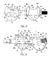
- Figure 1 is a front elevational view of an adjustable cervical collar in accordance with the invention.
- Figure 2 is a rear elevational view thereof.
- Figure 3 is a rear elevational view similar to Figure 2 but with the foam padding removed to illustrate the underlying construction of the parts.
- Figure 4 is a front elevational view similar to Figure 1 illustrating the collar in an adjusted position of use.
- a cervical collar in accordance with the invention comprises an anterior section, indicated generally at 1, a posterior section, indicated generally at 2, the two sections being interconnected by an elongated strap 3. All three of these parts are preferably formed from sheets of 1.59mm (1/16") high density polyethylene which is relatively stiff yet flexible.
- the sections 1 and 2 are covered on their rear surfaces with areas of cushioning material 4 and 5, respectively, the cushioning material being attached to the sections by means of plastic rivets 6.
- the cushioning material will be formed from pieces of 4.76-6.35mm (3/16"-1/4") close-celled polyethylene foam which is die-cut to conform to the configuration of the sections 1 and 2, including the throat exposing cut-out 7 in the anterior section and the ventilation cut-outs 8 in the posterior section.
- the anterior section 1 is also provided with a chin receiving cut-out 9 which also defines an opposing pair of mandible supports 10, 10a designed to control flexion, extension and rotation of the lower jaw.
- the cushioning material 4 is provided with an integral seat 11 adapted to fold outwardly over the lower edge of the cut-out 9 to provide padding along the edge of the cut-out 9 which contacts the wearer's lower jaw.
- the lowermost edge of the anterior section 1 is of outwardly curved configuration, indicated at 12, which provides for bracing between the underside of the mandible and the sternum.
- the lowermost edge of the cushioning material 4 is extended downwardly beyond the curved edge 12, as indicated at 13, again for the purpose of providing padding along an edge of the collar which contacts the wearer's body.
- the posterior section 2 of the collar is configured to provide an integral opposing pair of extensions 14, 14a which coact to provide right and left lateral support for the occipital support 15 extending along the upper edge of the posterior section 2 between the extension 14, 14a.
- the cushioning material 5 will extend upwardly beyond the occipital support 15 and the extensions 14, 14a in the areas where the uppermost portions of the posterior section contact the wearer's head, such extended areas being indicated at 16.
- the lowermost edge of the posterior section 2 is also of outwardly curved configuration, indicated at 17, to provide posterior thoracic spine support which, together with the occipital support, act to control extension.
- the cushioning 5 also extends downwardly beyond the curved edge 17, as indicated at 18, to provide padding where the posterior section of the collar contacts the wearer's body.
- the outermost ends of the curved lowermost edge 12 of the anterior section 1 terminates at its opposite ends in reversely curved areas 19, 19a which find counterparts 20, 20a at the outermost ends of the curved lowermost edge 17 of posterior section 2.
- the areas 19, 20 and 19a, 20a coact to provide right and left trapezius support which act to control lateral flexion.
- the anterior and posterior sections of the collar are adjustably interconnected by means of the elongated strap 3 which, as best seen in Figure 3, extends through a slot 21 in the anterior section 1, the strap having an opposing pair of ears 22 and 23 projecting laterally from the strap 3, the ears each having an opening 24 therein adapted to receive one of the plastic rivets 6 to thereby fixedly secure the strap 3 to the anterior section 1.
- the strap 3 also has an extension 25 of a size to lie between the chin receiving cut-out 9 and the underlying throat exposing cut-out 7, the strap terminating at its end in oppositely directed enlargements 26, 27 having openings 28 adapted to receive corresponding plastic rivets 6.
- the ears 22, 23, the extension 25, and the enlargements 26, 27 thus serve to reinforce and strengthen the anterior section 1 and serve as a means to securely fasten the strap 3 to the anterior section 1.
- the opposite end of the strap 3 extends through pairs of spaced apart slots 29, 29a and 30,30a formed in the opposite sides of posterior section 2, the pairs of slots defining webs 31 and 31a therebetween which act to slidably mount the posterior section 2 relative to the strap 3.
- the posterior section 2 mounts a pair of vertically extending braces 32 and 32a which serve to reinforce the posterior section in the areas of the extensions 14,14a and the webs 31 and 31a, the strap 3 slidably passing between the braces and the rear surface of the posterior section.
- the braces are provided with rivet receiving openings 24a and 28a which are adapted to receive the correspondingly positioned plastic rivets 6 which interconnect the parts.
- the braces 32 and 32a will be formed from the same material as the sections and strap.
- the strap 3 Adjacent its distal end the strap 3 is provided with a pair of plastic rivets 6a which serve as stops to establish the fully extended position of the posterior section 2 relative to the anterior section 1, the rivets 6a additionally serving to anchor an attachment tongue 33 the inner end of which extends through a slot 34 immediately adjacent the distal end of strap 3, the tongue 33 preferably comprising a strip of flexible material having a Velcro (registered trade mark) "eye" 35 (seen in Figure 2) on its rear surface, the tongue being engageable with an adhesively backed Velcro (registered trade mark) "hook” 36 adhesively secured to the outer surface of anterior section 1, as seen in Figure 1.
- Velcro registered trade mark
- the anterior and posterior sections are adjusted relative to each other by sliding the posterior section 2 along the strap 3 relative to the anterior section 1.
- printed indicia in the form of a series of dots or similar calibrations are provided on the outer surface of the strap 3 at equally spaced part intervals, such as 3.18mm (1/8"), by means of which rescue personnel may be guided in adjusting the distance between the anterior and posterior sections of the collar in accordance with the size of the wearer.
- the web 31 may be of a predetermined width, such as 25.4mm (1"), to further identify for rescue personnel the relative positions of the anterior and posterior sections as they encircle the wearer's neck, the sections of the collar being moveable from the fully extended position illustrated in Figure 1 to the fully contracted position illustrated in Figure 4, which may be on the order of 76.2mm (3") between the fully retracted and fully extended positions.
- the collar may be readily fitted to persons of different sizes with the assurance that all of the desired contact points will be properly positioned and utilized to immobilize the spine with control over extension, flexion, including lateral flexion, and also rotation.
Landscapes
- Health & Medical Sciences (AREA)
- Nursing (AREA)
- Orthopedic Medicine & Surgery (AREA)
- Engineering & Computer Science (AREA)
- Biomedical Technology (AREA)
- Heart & Thoracic Surgery (AREA)
- Vascular Medicine (AREA)
- Life Sciences & Earth Sciences (AREA)
- Animal Behavior & Ethology (AREA)
- General Health & Medical Sciences (AREA)
- Public Health (AREA)
- Veterinary Medicine (AREA)
- Orthopedics, Nursing, And Contraception (AREA)
Description
- This invention relates to cervical collars, and has to do more particularly with an adjustable cervical collar particularly suited for use in pre-hospital care applications.
- Numerous types of cervical collars have hitherto been proposed for treating neck injuries which result in muscular strain or nerve pressure in the cervical area. Extrication collars have become extremely important in field rescue operations to immobilize and maintain the cervical spine in a neutral position until a suspected injury can be diagnosed and treated. One such collar is the subject of US-A-4 520 801. The cervical collar has front and rear halves for resting on the shoulders and extending around the neck to support the chin and rear of the patient's head. The front half, through an angle, is split into upper and lower sections hinged relative to each other. The upper section has a U-shaped portion conforming to the shape of the patient's chin and extending along opposite sides of the lower jaw. A U-shaped bridge member on the upper section extends downwardly below the lower jaw and across the front of the neck region. The lower section extends around the lower front portion of the patient's neck and overlies the collarbone region and the central portion of the upper chest region. Fasteners extend through guide slots in the bridge member to provide means for guiding angular travel between the upper and lower sections. The fasteners can be loosened to permit angular travel and tightened to hold the upper and lower sections in a preset angular position to conform to different neck sizes. The bridge member bridges the space between the chin-supporting upper section and the lower section to add rigidity to the chin-supporting portion of the collar. Flexible straps with Velcro fasteners on the rear half are attached to cooperating Velcro fasteners on the front half to hold the collar in place around the patient's neck.
- While surgical collars are presently available which are intended for field rescue use, such devices have left much to be desired with regard to their ease of application as well as their ability to meet other criteria which have been found desirable in a device intended for field use. The present invention overcomes these difficulties by providing a cervical collar specifically designed for rescue uses which not only provides the structural relationships necessary to achieve immobilization of the cervical spine but also provides a structure which may be readily adjusted to accommodate persons of different sizes.
- Accordingly, the invention provides an adjustable cervical collar comprising an anterior section, a posterior section, one elongate strap extending between and interconnecting the said sections, the said sections being substantially rigid, attachment means connecting the strap to one of the said sections, and fastener means connecting the opposite end of the strap to the other of the said sections, whereby to adjust the position of the said sections relative to each other and to the anatomy of the wearer, characterized in that the elongate strap slidably interconnects the said sections, the said sections and the strap are relatively stiff yet flexible, e.g. high density polyethylene, and therefore capable of being conformed to the contours of the wearer's anatomy, the attachment means slidably connect the strap to the said one of the sections with one end of the strap projecting freely outwardly beyond that section, stop means are provided on the strap to prevent its detachment from that section to which it is slidably connected, and securement means are provided on the free end of the strap for securing the collar round the wearer's neck.
- Preferably, the collar is of one-piece design, being composed of a series of interconnected high density polyethylene parts covered in all critical anatomy contacting areas with polyethylene foam, the parts being joined together by plastic rivets.
- A Velcro fastening system may be provided to facilitate rapid application of the collar, as well as provide for easy removal.
- An all plastic construction makes the collar easy to clean, and also makes it compatible with MRI, CT, and X-ray machines, as well as providing a collar which is useable over a wide temperature range.
- In addition to its utility in the field, the collar of the present invention provides a thin side profile which allows it to be easily slipped behind the wearer's neck and also permits the collars to be readily stored in an emergency vehicle either in flat condition or folded to fit into a small storage compartment. Being adjustable to accommodate a number of sizes eliminates the necessity for carrying an assortment of collars of different sizes and hence further reduces the storage space requirements in the rescue vehicle.
- A collar constructed in accordance with a preferred embodiment of the present invention is simple and inexpensive to manufacture in that it comprises a series of die-cut parts which are readily assembled utilizing plastic rivets and hence there are minimum tooling requirements.
- Figure 1 is a front elevational view of an adjustable cervical collar in accordance with the invention.
- Figure 2 is a rear elevational view thereof.
- Figure 3 is a rear elevational view similar to Figure 2 but with the foam padding removed to illustrate the underlying construction of the parts.
- Figure 4 is a front elevational view similar to Figure 1 illustrating the collar in an adjusted position of use.
- Referring first to Figure 1 of the drawings, a cervical collar in accordance with the invention comprises an anterior section, indicated generally at 1, a posterior section, indicated generally at 2, the two sections being interconnected by an
elongated strap 3. All three of these parts are preferably formed from sheets of 1.59mm (1/16") high density polyethylene which is relatively stiff yet flexible. - As best seen in Figure 2, the
sections 1 and 2 are covered on their rear surfaces with areas ofcushioning material plastic rivets 6. Preferably the cushioning material will be formed from pieces of 4.76-6.35mm (3/16"-1/4") close-celled polyethylene foam which is die-cut to conform to the configuration of thesections 1 and 2, including the throat exposing cut-out 7 in the anterior section and the ventilation cut-outs 8 in the posterior section. The anterior section 1 is also provided with a chin receiving cut-out 9 which also defines an opposing pair ofmandible supports 10, 10a designed to control flexion, extension and rotation of the lower jaw. Since the lower jaw will rest on the chin receiving cut-out 9, thecushioning material 4 is provided with an integral seat 11 adapted to fold outwardly over the lower edge of the cut-out 9 to provide padding along the edge of the cut-out 9 which contacts the wearer's lower jaw. - The lowermost edge of the anterior section 1 is of outwardly curved configuration, indicated at 12, which provides for bracing between the underside of the mandible and the sternum. Preferably, the lowermost edge of the
cushioning material 4 is extended downwardly beyond thecurved edge 12, as indicated at 13, again for the purpose of providing padding along an edge of the collar which contacts the wearer's body. - The
posterior section 2 of the collar is configured to provide an integral opposing pair ofextensions occipital support 15 extending along the upper edge of theposterior section 2 between theextension cushioning material 5 will extend upwardly beyond theoccipital support 15 and theextensions - The lowermost edge of the
posterior section 2 is also of outwardly curved configuration, indicated at 17, to provide posterior thoracic spine support which, together with the occipital support, act to control extension. Thecushioning 5 also extends downwardly beyond thecurved edge 17, as indicated at 18, to provide padding where the posterior section of the collar contacts the wearer's body. - It also will be noted that the outermost ends of the curved
lowermost edge 12 of the anterior section 1 terminates at its opposite ends in reverselycurved areas counterparts 20, 20a at the outermost ends of the curvedlowermost edge 17 ofposterior section 2. Theareas - As previously indicated, the anterior and posterior sections of the collar are adjustably interconnected by means of the
elongated strap 3 which, as best seen in Figure 3, extends through aslot 21 in the anterior section 1, the strap having an opposing pair ofears strap 3, the ears each having anopening 24 therein adapted to receive one of theplastic rivets 6 to thereby fixedly secure thestrap 3 to the anterior section 1. Thestrap 3 also has an extension 25 of a size to lie between the chin receiving cut-out 9 and the underlying throat exposing cut-out 7, the strap terminating at its end in oppositely directedenlargements openings 28 adapted to receive correspondingplastic rivets 6. Theears enlargements strap 3 to the anterior section 1. - The opposite end of the
strap 3 extends through pairs of spaced apartslots posterior section 2, the pairs ofslots defining webs posterior section 2 relative to thestrap 3. On its rear surface theposterior section 2 mounts a pair of vertically extendingbraces extensions webs strap 3 slidably passing between the braces and the rear surface of the posterior section. As is the case of theears enlargements openings plastic rivets 6 which interconnect the parts. Preferably thebraces - Adjacent its distal end the
strap 3 is provided with a pair ofplastic rivets 6a which serve as stops to establish the fully extended position of theposterior section 2 relative to the anterior section 1, therivets 6a additionally serving to anchor anattachment tongue 33 the inner end of which extends through aslot 34 immediately adjacent the distal end ofstrap 3, thetongue 33 preferably comprising a strip of flexible material having a Velcro (registered trade mark) "eye" 35 (seen in Figure 2) on its rear surface, the tongue being engageable with an adhesively backed Velcro (registered trade mark) "hook" 36 adhesively secured to the outer surface of anterior section 1, as seen in Figure 1. - In applying the collar to an injured person and depending upon the person's size, the anterior and posterior sections are adjusted relative to each other by sliding the
posterior section 2 along thestrap 3 relative to the anterior section 1. To this end, printed indicia in the form of a series of dots or similar calibrations are provided on the outer surface of thestrap 3 at equally spaced part intervals, such as 3.18mm (1/8"), by means of which rescue personnel may be guided in adjusting the distance between the anterior and posterior sections of the collar in accordance with the size of the wearer. To this end, theweb 31 may be of a predetermined width, such as 25.4mm (1"), to further identify for rescue personnel the relative positions of the anterior and posterior sections as they encircle the wearer's neck, the sections of the collar being moveable from the fully extended position illustrated in Figure 1 to the fully contracted position illustrated in Figure 4, which may be on the order of 76.2mm (3") between the fully retracted and fully extended positions. With this arrangement, the collar may be readily fitted to persons of different sizes with the assurance that all of the desired contact points will be properly positioned and utilized to immobilize the spine with control over extension, flexion, including lateral flexion, and also rotation. - Modifications of detail may be made in the invention without departing from its scope.
Claims (11)
- An adjustable cervical collar comprising an anterior section (1), a posterior section (2), one elongate strap (3) extending between and interconnecting the said sections (1,2), the said sections (1,2) being substantially rigid, attachment means (29,29a,30,30a,31,31a) connecting the strap (3) to one of the said sections (2), and fastener means (24,28) connecting the opposite end of the strap (3) to the other of the said sections (1), whereby to adjust the position of the said sections (1,2) relative to each other and to the anatomy of the wearer, characterized in that the elongate strap slidably interconnects the said sections, the said sections (1,2) and the strap (3) are relatively stiff yet flexible, e.g. high density polyethylene, and therefore capable of being conformed to the contours of the wearer's anatomy, the attachment means slidably connect the strap (3) to the said one of the sections (2) with one end (33) of the strap (3) projecting freely outwardly beyond that section (2), stop means (6a) are provided on the strap (3) to prevent its detachment from that section (2) to which it is slidably connected, and securement means (35,36) are provided on the free end (33) of the strap (3) for securing the collar around the wearer's neck.
- A cervical collar as claimed in Claim 1 wherein the means slidably connecting said strap (3) to one of said sections (2) comprises pairs of spaced apart slots (29,29a,30,30a) in said last named section defining webs (31,31a) in said section (2) beneath which said strap (3) extends, and stop means (6a) on said strap (3) positioned to engage one of said webs (31a) to establish the fully extended position of said last named section relative to said strap (3).
- A cervical collar as claimed in Claim 1 or 2 wherein the rear surface of each section is covered with a cushioning material (4,5), and wherein said attachment means (6) also serve to secure said cushioning material (4,5) to said surface.
- A cervical collar as claimed in Claim 3 wherein said anterior section (1) is configured to provide a centrally disposed chin receiving opening (9) extending downward from its upper edge, and wherein said cushioning material (4) includes an integral seat (11) in the area of said chin receiving opening (9) adapted to be folded outwardly over the lowermost edge of said opening (9).
- A cervical collar as claimed in Claim 4 including an opposing pair of mandible supports (10,10a) extending inwardly from the opposite sides of said chin receiving opening (9).
- A cervical collar as claimed in Claim 3, 4, or 5 wherein the lowermost edge of said anterior section (1) is of outwardly curved configuration (12), and wherein said cushioning material (4) projects downwardly beyond said lowermost edge (12).
- A cervical collar as claimed in any of Claims 3-6 wherein said posterior section (2) is configured to provide a centrally disposed occipital support (15) on its uppermost edge, said occipital support terminating at its opposite ends in a pair of upwardly projecting extensions (14), and wherein said cushioning material (5) extends upwardly beyond said occipital support and said extensions.
- A cervical collar as claimed in any one of Claims 3-7 wherein the lowermost edge (17) of said posterior section (2) is of outwardly curved configuration, and wherein said cushioning material (5) extends downwardly beyond said lowermost edge (17).
- A cervical collar as claimed in any preceding Claim wherein said strap (3) is secured to the other of said sections (1) by means of a slot (21) in that section through which said strap (3) passes, and a pair of laterally projecting ears (22,23) on said strap (3) lying immediately beyond said slot (21).
- A cervical collar as claimed in Claim 9 wherein the other of said sections comprises the anterior section (1) and has a centrally disposed chin receiving cut-out (9) extending downwardly from its upper edge, wherein said strap (3) includes an extension (25), the upper edge of which coincides with the lowermost edge of said cut-out (9), and wherein said extension (25) terminates in upper and lower enlargements (26,27) lying beyond said cut-out, said strap (3) being secured to said anterior section by means of fasteners (24,28) connecting said ears (22,23) and said enlargements (26,27) to said anterior section.
- A cervical collar as claimed in Claim 2 wherein said strap (3) is slidably connected to said posterior section (2) and wherein said posterior section (2) has a spaced apart pair of braces (32,32a) secured to its rear surface in the areas of said webs (31,31a), said strap (3) extending between said braces (32,32a) and the rear surface of said posterior section.
Applications Claiming Priority (2)
| Application Number | Priority Date | Filing Date | Title |
|---|---|---|---|
| US07/143,362 US5058572A (en) | 1988-01-12 | 1988-01-12 | Adjustable cervical collar |
| US143362 | 1988-01-12 |
Publications (2)
| Publication Number | Publication Date |
|---|---|
| EP0324591A1 EP0324591A1 (en) | 1989-07-19 |
| EP0324591B1 true EP0324591B1 (en) | 1993-05-05 |
Family
ID=22503742
Family Applications (1)
| Application Number | Title | Priority Date | Filing Date |
|---|---|---|---|
| EP89300200A Expired - Lifetime EP0324591B1 (en) | 1988-01-12 | 1989-01-11 | Adjustable cervical collar |
Country Status (8)
| Country | Link |
|---|---|
| US (1) | US5058572A (en) |
| EP (1) | EP0324591B1 (en) |
| JP (1) | JPH01268552A (en) |
| KR (1) | KR890011576A (en) |
| AU (1) | AU613139B2 (en) |
| CA (1) | CA1320880C (en) |
| DE (2) | DE68906272T2 (en) |
| ES (1) | ES2015511T3 (en) |
Cited By (1)
| Publication number | Priority date | Publication date | Assignee | Title |
|---|---|---|---|---|
| US20220280328A1 (en) * | 2009-08-10 | 2022-09-08 | Ossur Hf | Cervical collar having height and circumferential adjustment |
Families Citing this family (39)
| Publication number | Priority date | Publication date | Assignee | Title |
|---|---|---|---|---|
| US5520619A (en) * | 1993-05-20 | 1996-05-28 | Ambu International A/S | Adjustable cervical collar |
| US5993403A (en) | 1993-05-20 | 1999-11-30 | Ambu International A/S | Adjustable cervical collar |
| US5366438A (en) * | 1993-05-20 | 1994-11-22 | Martin Sr Bill | Cervical collar |
| US6036664A (en) * | 1994-02-22 | 2000-03-14 | Ambu International A/S | Automatic adjustable cervical collar |
| US6726643B1 (en) | 1994-02-22 | 2004-04-27 | Ambu International A/S | Automatic adjustable cervical collar |
| US5622529A (en) * | 1994-06-08 | 1997-04-22 | Calabrese; Salvatore | Flat cervical collar having a unitary chin support |
| US5593382A (en) * | 1994-09-29 | 1997-01-14 | Rudy, Jr.; Ronald M. | Extrication cervical collar with adjustable supports |
| AU731411B2 (en) * | 1995-11-30 | 2001-03-29 | Ambu International A/S | Collapsible cervical collar |
| USD393718S (en) | 1996-12-23 | 1998-04-21 | Laerdal Medical Corporation | Cervical collar |
| US5795315A (en) * | 1996-12-23 | 1998-08-18 | Laerdal Medical Corporation | Multiple-size cervical collar |
| US6056711A (en) * | 1997-06-26 | 2000-05-02 | Beiersdorf, Inc. | Adjustable cervical collar |
| US6045522A (en) * | 1997-11-03 | 2000-04-04 | Grober; Arieh | Cervical spine traction apparatus |
| US6423020B1 (en) | 1999-01-14 | 2002-07-23 | Ferno-Washington, Inc. | Cervical extrication collar |
| US6398747B1 (en) | 1999-10-27 | 2002-06-04 | Ambu Inc. | Cervical immobilizing device |
| US6494854B1 (en) * | 1999-10-28 | 2002-12-17 | Pmt Corporation | Cervical collar device |
| US7297127B2 (en) * | 2001-03-19 | 2007-11-20 | Ambu Inc. | Cervical immobilization device |
| US20060135897A1 (en) * | 2004-12-21 | 2006-06-22 | Dellanno Ronald P | Forward head posture correction collar |
| US7041073B1 (en) * | 2005-05-02 | 2006-05-09 | Martin Rizo Patron | Custom fit cervical collar |
| JP4317257B2 (en) * | 2006-07-07 | 2009-08-19 | ハセガワ株式会社 | Foldable cervical vertebra protective band |
| WO2010065104A1 (en) * | 2008-12-03 | 2010-06-10 | Ossur Hf | Cervical collar having height and circumferential adjustment |
| US8679044B2 (en) | 2008-12-03 | 2014-03-25 | Ossur Hf | Cervical collar with reduced vascular obstruction |
| USD616997S1 (en) | 2009-09-14 | 2010-06-01 | Ossur Hf | Orthopedic device |
| USD616996S1 (en) | 2009-09-14 | 2010-06-01 | Ossur Hf | Orthopedic device |
| USD616555S1 (en) | 2009-09-14 | 2010-05-25 | Ossur Hf | Orthopedic device |
| USD647623S1 (en) | 2010-08-06 | 2011-10-25 | Ossur Hf | Height adjustment mechanism for cervical collar |
| USD647624S1 (en) | 2010-08-06 | 2011-10-25 | Ossur Hf | Cervical collar |
| US8491512B2 (en) | 2010-08-26 | 2013-07-23 | Clear Advantage Collar, Inc. | Adjustable cervical collar |
| USD659842S1 (en) | 2010-08-26 | 2012-05-15 | Clear Advantage Collar, Inc. | Cervical collar |
| WO2013176985A1 (en) | 2012-05-21 | 2013-11-28 | Ossur Hf | Cervical collar |
| US9687380B1 (en) | 2014-05-12 | 2017-06-27 | David L. Falk | Cervical collar brace kit, collar blanks, methods of forming a model of a patient, and methods of forming collar blanks |
| US20160015548A1 (en) * | 2014-07-16 | 2016-01-21 | Frederic W. Heyman | Patient treatment system |
| EP3280367B1 (en) | 2015-04-06 | 2020-07-29 | Ossur Iceland EHF | Cervical collar having height adjustment |
| WO2017147447A1 (en) | 2016-02-25 | 2017-08-31 | Ossur Iceland Ehf | Cervical collar having height adjustment |
| US10945872B2 (en) | 2016-09-19 | 2021-03-16 | Ossur Iceland Ehf | Cervical collar |
| GB201616282D0 (en) * | 2016-09-26 | 2016-11-09 | University College Cardiff Consultants Limited | Brace |
| USD870899S1 (en) | 2017-09-06 | 2019-12-24 | Ossur Iceland Ehf | Cervical collar |
| USD866773S1 (en) | 2017-09-06 | 2019-11-12 | Ossur Iceland Ehf | Cervical collar |
| KR102169310B1 (en) * | 2018-08-08 | 2020-10-23 | 주식회사 쉬즈원 | A Neck Wearing Device |
| CN111920606A (en) * | 2020-08-21 | 2020-11-13 | 邢力丹 | Neck strutting arrangement and nursing wheelchair thereof |
Family Cites Families (11)
| Publication number | Priority date | Publication date | Assignee | Title |
|---|---|---|---|---|
| US441369A (en) * | 1890-11-25 | Adjustable pattern for drafting garments | ||
| US2389690A (en) * | 1945-11-27 | Cervical collar | ||
| US4308010A (en) * | 1978-08-21 | 1981-12-29 | Orthoband Company, Inc. | Neck pad material and a method for its manufacture |
| USRE32219E (en) * | 1981-10-16 | 1986-08-05 | Portable cervical collar | |
| DE3308571A1 (en) * | 1983-03-10 | 1984-09-13 | Walter 7000 Stuttgart Auracher | OTHOPEDIC NECK AND HEADREST |
| US4520801A (en) * | 1983-07-08 | 1985-06-04 | Max Lerman | Cervical collar |
| US4708129A (en) * | 1983-12-19 | 1987-11-24 | Pujals Jr Charles | Cervical/occipital support |
| US4640269A (en) * | 1984-07-30 | 1987-02-03 | Joan Goins | Back brace having strap with widened middle portion for pad |
| US4677969A (en) * | 1984-09-28 | 1987-07-07 | Charles Griener And Company, Inc. | Cervical collar permitting tracheotomy |
| US4712540A (en) * | 1985-05-16 | 1987-12-15 | Jobst Institute | Cervical collar |
| US4681097A (en) * | 1986-01-23 | 1987-07-21 | Pansiera Timothy T | Orthopedic brace |
-
1988
- 1988-01-12 US US07/143,362 patent/US5058572A/en not_active Expired - Fee Related
-
1989
- 1989-01-10 KR KR1019890000195A patent/KR890011576A/en not_active Ceased
- 1989-01-11 AU AU28405/89A patent/AU613139B2/en not_active Ceased
- 1989-01-11 EP EP89300200A patent/EP0324591B1/en not_active Expired - Lifetime
- 1989-01-11 DE DE89300200T patent/DE68906272T2/en not_active Expired - Fee Related
- 1989-01-11 CA CA000587914A patent/CA1320880C/en not_active Expired - Fee Related
- 1989-01-11 ES ES198989300200T patent/ES2015511T3/en not_active Expired - Lifetime
- 1989-01-11 DE DE198989300200T patent/DE324591T1/en active Pending
- 1989-01-12 JP JP1005841A patent/JPH01268552A/en active Pending
Cited By (2)
| Publication number | Priority date | Publication date | Assignee | Title |
|---|---|---|---|---|
| US20220280328A1 (en) * | 2009-08-10 | 2022-09-08 | Ossur Hf | Cervical collar having height and circumferential adjustment |
| US12370072B2 (en) * | 2009-08-10 | 2025-07-29 | Ossur Hf | Cervical collar having height and circumferential adjustment |
Also Published As
| Publication number | Publication date |
|---|---|
| ES2015511T3 (en) | 1993-10-01 |
| KR890011576A (en) | 1989-08-21 |
| US5058572A (en) | 1991-10-22 |
| ES2015511A4 (en) | 1990-09-01 |
| DE68906272D1 (en) | 1993-06-09 |
| AU613139B2 (en) | 1991-07-25 |
| JPH01268552A (en) | 1989-10-26 |
| DE68906272T2 (en) | 1993-11-04 |
| CA1320880C (en) | 1993-08-03 |
| DE324591T1 (en) | 1990-09-06 |
| AU2840589A (en) | 1989-07-13 |
| EP0324591A1 (en) | 1989-07-19 |
Similar Documents
| Publication | Publication Date | Title |
|---|---|---|
| US5058572A (en) | Adjustable cervical collar | |
| US5027833A (en) | Extrication and spinal restraint device | |
| US4401111A (en) | Cervical spine collar | |
| US4836195A (en) | Device for abduction of upper limbs | |
| US10792180B2 (en) | Cervical collar | |
| US4979520A (en) | Pediatric device for immobilizing injured infant utilizing a standard size backboard | |
| US6254560B1 (en) | Cervical collars | |
| US5014374A (en) | Restraint stretcher | |
| US4665908A (en) | Extrication and spinal restraint device | |
| AU2009329342B2 (en) | Spinal immobilisation | |
| US4582051A (en) | Cervical collar with circumferential and vertical height adjustability and stability | |
| US4976257A (en) | Hyperextension brace | |
| US5788658A (en) | Field adjustable extrication collar | |
| US5657766A (en) | Head and neck immobilizer | |
| US4143654A (en) | Universal short spine board system | |
| US5515869A (en) | Pediatric spinal immobilization and airway control board | |
| CA2225128C (en) | Multiple-size cervical collar | |
| US5205813A (en) | Cephalic and cervical support appliance | |
| US8356604B2 (en) | Immobilization device | |
| US20110118639A1 (en) | Immobilization device | |
| US8545423B2 (en) | Custom fit cervical collar | |
| GB2453996A (en) | Adjustable cervical collar with size indicating means | |
| US4676233A (en) | Manually formed splints having sheet metal structure | |
| US20110009789A1 (en) | Cervical Spine Immobilization Device | |
| US6467486B1 (en) | Extricating device for persons with spinal injuries |
Legal Events
| Date | Code | Title | Description |
|---|---|---|---|
| PUAI | Public reference made under article 153(3) epc to a published international application that has entered the european phase |
Free format text: ORIGINAL CODE: 0009012 |
|
| AK | Designated contracting states |
Kind code of ref document: A1 Designated state(s): DE ES FR GB IT |
|
| 17P | Request for examination filed |
Effective date: 19891228 |
|
| ITCL | It: translation for ep claims filed |
Representative=s name: STUDIO TORTA SOCIETA' SEMPLICE |
|
| EL | Fr: translation of claims filed | ||
| DET | De: translation of patent claims | ||
| 17Q | First examination report despatched |
Effective date: 19910513 |
|
| GRAA | (expected) grant |
Free format text: ORIGINAL CODE: 0009210 |
|
| AK | Designated contracting states |
Kind code of ref document: B1 Designated state(s): DE ES FR GB IT |
|
| REF | Corresponds to: |
Ref document number: 68906272 Country of ref document: DE Date of ref document: 19930609 |
|
| ET | Fr: translation filed | ||
| ITF | It: translation for a ep patent filed | ||
| REG | Reference to a national code |
Ref country code: ES Ref legal event code: FG2A Ref document number: 2015511 Country of ref document: ES Kind code of ref document: T3 |
|
| PGFP | Annual fee paid to national office [announced via postgrant information from national office to epo] |
Ref country code: GB Payment date: 19931220 Year of fee payment: 6 |
|
| PGFP | Annual fee paid to national office [announced via postgrant information from national office to epo] |
Ref country code: FR Payment date: 19940111 Year of fee payment: 6 |
|
| PGFP | Annual fee paid to national office [announced via postgrant information from national office to epo] |
Ref country code: ES Payment date: 19940120 Year of fee payment: 6 |
|
| PGFP | Annual fee paid to national office [announced via postgrant information from national office to epo] |
Ref country code: DE Payment date: 19940127 Year of fee payment: 6 |
|
| PLBE | No opposition filed within time limit |
Free format text: ORIGINAL CODE: 0009261 |
|
| STAA | Information on the status of an ep patent application or granted ep patent |
Free format text: STATUS: NO OPPOSITION FILED WITHIN TIME LIMIT |
|
| 26N | No opposition filed | ||
| PG25 | Lapsed in a contracting state [announced via postgrant information from national office to epo] |
Ref country code: GB Effective date: 19950111 |
|
| PG25 | Lapsed in a contracting state [announced via postgrant information from national office to epo] |
Ref country code: ES Free format text: LAPSE BECAUSE OF NON-PAYMENT OF DUE FEES Effective date: 19950112 |
|
| GBPC | Gb: european patent ceased through non-payment of renewal fee |
Effective date: 19950111 |
|
| PG25 | Lapsed in a contracting state [announced via postgrant information from national office to epo] |
Ref country code: FR Effective date: 19950929 |
|
| PG25 | Lapsed in a contracting state [announced via postgrant information from national office to epo] |
Ref country code: DE Effective date: 19951003 |
|
| REG | Reference to a national code |
Ref country code: FR Ref legal event code: ST |
|
| REG | Reference to a national code |
Ref country code: ES Ref legal event code: FD2A Effective date: 19990405 |
|
| PG25 | Lapsed in a contracting state [announced via postgrant information from national office to epo] |
Ref country code: IT Free format text: LAPSE BECAUSE OF NON-PAYMENT OF DUE FEES;WARNING: LAPSES OF ITALIAN PATENTS WITH EFFECTIVE DATE BEFORE 2007 MAY HAVE OCCURRED AT ANY TIME BEFORE 2007. THE CORRECT EFFECTIVE DATE MAY BE DIFFERENT FROM THE ONE RECORDED. Effective date: 20050111 |