EP0323019A1 - Gauge for measuring bending of structures - Google Patents
Gauge for measuring bending of structures Download PDFInfo
- Publication number
- EP0323019A1 EP0323019A1 EP88310952A EP88310952A EP0323019A1 EP 0323019 A1 EP0323019 A1 EP 0323019A1 EP 88310952 A EP88310952 A EP 88310952A EP 88310952 A EP88310952 A EP 88310952A EP 0323019 A1 EP0323019 A1 EP 0323019A1
- Authority
- EP
- European Patent Office
- Prior art keywords
- bending
- bar
- gauge
- measuring
- bend
- Prior art date
- Legal status (The legal status is an assumption and is not a legal conclusion. Google has not performed a legal analysis and makes no representation as to the accuracy of the status listed.)
- Ceased
Links
- 238000005452 bending Methods 0.000 title claims abstract description 82
- 238000000034 method Methods 0.000 claims description 13
- 230000000063 preceeding effect Effects 0.000 claims 3
- 238000005259 measurement Methods 0.000 abstract description 5
- 239000002184 metal Substances 0.000 description 10
- 230000000694 effects Effects 0.000 description 7
- 239000000853 adhesive Substances 0.000 description 3
- 230000001070 adhesive effect Effects 0.000 description 3
- 230000035945 sensitivity Effects 0.000 description 2
- 238000007796 conventional method Methods 0.000 description 1
- 238000005260 corrosion Methods 0.000 description 1
- 230000007797 corrosion Effects 0.000 description 1
- 230000007613 environmental effect Effects 0.000 description 1
- 238000003780 insertion Methods 0.000 description 1
- 230000037431 insertion Effects 0.000 description 1
- 238000004519 manufacturing process Methods 0.000 description 1
- 238000011089 mechanical engineering Methods 0.000 description 1
- 230000007935 neutral effect Effects 0.000 description 1
- 238000013001 point bending Methods 0.000 description 1
- 230000001681 protective effect Effects 0.000 description 1
- 230000003068 static effect Effects 0.000 description 1
Images


Classifications
-
- G—PHYSICS
- G01—MEASURING; TESTING
- G01M—TESTING STATIC OR DYNAMIC BALANCE OF MACHINES OR STRUCTURES; TESTING OF STRUCTURES OR APPARATUS, NOT OTHERWISE PROVIDED FOR
- G01M5/00—Investigating the elasticity of structures, e.g. deflection of bridges or air-craft wings
- G01M5/0083—Investigating the elasticity of structures, e.g. deflection of bridges or air-craft wings by measuring variation of impedance, e.g. resistance, capacitance, induction
-
- G—PHYSICS
- G01—MEASURING; TESTING
- G01B—MEASURING LENGTH, THICKNESS OR SIMILAR LINEAR DIMENSIONS; MEASURING ANGLES; MEASURING AREAS; MEASURING IRREGULARITIES OF SURFACES OR CONTOURS
- G01B5/00—Measuring arrangements characterised by the use of mechanical techniques
- G01B5/30—Measuring arrangements characterised by the use of mechanical techniques for measuring the deformation in a solid, e.g. mechanical strain gauge
-
- G—PHYSICS
- G01—MEASURING; TESTING
- G01B—MEASURING LENGTH, THICKNESS OR SIMILAR LINEAR DIMENSIONS; MEASURING ANGLES; MEASURING AREAS; MEASURING IRREGULARITIES OF SURFACES OR CONTOURS
- G01B7/00—Measuring arrangements characterised by the use of electric or magnetic techniques
- G01B7/16—Measuring arrangements characterised by the use of electric or magnetic techniques for measuring the deformation in a solid, e.g. by resistance strain gauge
-
- G—PHYSICS
- G01—MEASURING; TESTING
- G01M—TESTING STATIC OR DYNAMIC BALANCE OF MACHINES OR STRUCTURES; TESTING OF STRUCTURES OR APPARATUS, NOT OTHERWISE PROVIDED FOR
- G01M5/00—Investigating the elasticity of structures, e.g. deflection of bridges or air-craft wings
- G01M5/0025—Investigating the elasticity of structures, e.g. deflection of bridges or air-craft wings of elongated objects, e.g. pipes, masts, towers or railways
-
- G—PHYSICS
- G01—MEASURING; TESTING
- G01M—TESTING STATIC OR DYNAMIC BALANCE OF MACHINES OR STRUCTURES; TESTING OF STRUCTURES OR APPARATUS, NOT OTHERWISE PROVIDED FOR
- G01M5/00—Investigating the elasticity of structures, e.g. deflection of bridges or air-craft wings
- G01M5/0041—Investigating the elasticity of structures, e.g. deflection of bridges or air-craft wings by determining deflection or stress
Definitions
- This invention relates to a gauge and in particular a gauge for measuring bending of structures.
- An alternative method of measuring bending stresses is by clamping gauge bars around the structure and measuring the changes in length of the bars.
- This method is an extension of the above method, but the requirement for taking the structure out of service is removed.
- the main disadvantage of this method is that the clamps that hold the gauge bars must be very rigid and must not move relative to the structure. This may make them difficult to install.
- a large number of gauge bars must be installed between the clamps. This results in a stiffening of the structure thereby reducing the bending over the section being measured and causing errors in the measurements being recorded.
- the physical form of the equipment used results in an increase in the local effect of the environment, for example, waves and currents etc. on the structure. Once installed the equipment has to be calibrated by subjecting the structure to known bends or loads, a procedure which can prove to be difficult.
- each measured strain is the combination of that caused by bending and that caused by the overall tension in the structure.
- further calculation may be required to obtain the actual bending stresses.
- the effect of tension in the structure may also be removed by mounting the strain gauges or gauge bars in bridge arrangements but for good directional sensitivity more than one bridge arrangement may be required and this increases the problems associated with fixing the gauges or the bars to the structure.
- a gauge suitable for measuring bending of a structure comprising a bending bar having means for attaching the bar to the structure and means for measuring bending of the bar, the attaching means being adapted to allow the bar to bend in response to bending of the structure, whereby measurement of bending of the bar enables bending of the structure to be determined.
- the attaching means may comprise clamps with mountings, which allow at least part of the bar to move longitudinally along its axis with respect to the structure.
- the mountings may be longitudinally slideable mountings or may be flexible plates which are free to bend to allow at least part of the bar to move along its axis.
- part of the bar is attached to the structure so that it cannot move in any direction with respect to the structure.
- the bar may have any suitable cross-section and may be hollow.
- the bar may be uniform throughout its length.
- the bend measuring means may be one or more strain measuring devices mounted on the bending bar.
- the strain measuring devices are strain gauges and most preferably, the bending bar is hollow and the bend measuring means comprises one or more strain gauges mounted on the inner surface of the hollow bending bar.
- the strain gauges may be connected to amplifiers in an enclosure which may be mounted at the part of the bar which is fixed rigidly to the structure, or may be mounted remotely from the bending bar.
- the bend measuring means may comprise one or more bridge arrangements each comprising four strain gauges mounted as opposed pairs on the bending bar and connected to a bend output amplifier.
- the bend measuring means comprises a pair of four-strain-gauge-bridge arrangements mounted orthogonal to one another.
- the bend measuring means comprises more than one pair of four-strain-gauge-bridge arrangements.
- the bend measuring means comprises a single strain measuring device mounted on the bending bar then a bend having a component with a radius parallel to the line between the neutral axis of the bar and the device may be measured. It is further envisaged that if the bend measuring means comprises four strain gauges mounted in opposed pairs in a strain gauge bridge arrangement on the bending bar then a bend component having a radius paralled to the line between the pairs of gauges may be measured. It is yet further envisaged that if the bend measuring means comprises a pair of four-strain-gauge-bridge arrangements mounted orthogonal to one another then a bend of the bending bar and hence the structure may be expressed as two orthogonal components each corresponding to one of the bridges.
- the bend measuring means of the bending bar may be calibrated prior to attaching it to the structure.
- the attaching means allows the bending bar to bend in response to dynamic bending of the structure, and so by measuring bending of the bending bar, the bending of the structure may be determined.
- the bending stresses in the structure may be calculated from the bending of the structure by known techniques.
- the static bend of the structure may be determined from the initial bend of the bending bar in the absence of irregularities in the surface of the structure or the attaching means and the like.
- the effect of tension in the structure on the bending bar and hence the bend measuring means is reduced.
- the effect of tension in the structure on the bending bar may be removed by mounting strain gauges in a bridge arrangement.
- the bending bar is free to move longitudinally along its axis with respect to the structure, it is believed to be possible to measure bending stresses in the structure up to the yield stress of the structure. It is believed that this also has a less stiffening effect on the structure than a plurality of rigidly mounted gauge bars.
- the gauge according to the present invention may be used to measure bending in structures such as subsea risers on oil rigs. It is believed that the gauge of the present invention offers the advantage of limiting the effect of the gauge on the stiffness and local environmental effect on the structure so that more reliable measurements may be made.
- the number of stain gauges mounted inside a hollow bending bar may be increased to increase the sensitivity of the measurements without increasing the effect of the gauge on the stiffness of the structure or other associated disadvantages.
- the gauge according to the present invention may have numerous other applications, for example, for measuring bending in structures such as bridges, subsea pipelines, buildings, crane jibs, oil exploration and production platforms and the like. It may also be used where access to only one side of a structure is available or where it is difficult or undesirable to fix strain gauges directly to the structure.
- the present invention there is also provided a method for measuring bending of structures using the gauge as herein described.
- the method comprising attaching to the structure a gauge according to the present invention so that the bending bar bends in response to bending of the structure and measuring the bending of the bar so as to determine bending of the structure.
Landscapes
- Physics & Mathematics (AREA)
- General Physics & Mathematics (AREA)
- Engineering & Computer Science (AREA)
- Aviation & Aerospace Engineering (AREA)
- Measurement Of Length, Angles, Or The Like Using Electric Or Magnetic Means (AREA)
- A Measuring Device Byusing Mechanical Method (AREA)
- Investigating Strength Of Materials By Application Of Mechanical Stress (AREA)
Abstract
A gauge for measuring bending of structures comprises a bending bar which may be attached to the structure so that it bends in response to bending of the structure and having means for measuring bending of the bar whereby measurement of bending of the bar enables bending of the structure to be determined. Preferably, the bar is hollow with strain gauges on its inner surface and is attached so that at least part of it may move longitudinally along its axis with respect to the stucture.
Description
- This invention relates to a gauge and in particular a gauge for measuring bending of structures.
- Bending stresses in structures such as metal subsea risers can cause fatigue which reduces the working life of the structure, hence it is of considerable importance to know the magnitude of these stresses. Known methods of measuring these stresses include fixing strain gauges directly to the stressed metal of the structure. Usually any protective coat on the structure has to be removed to gain access to the metal which may increase the risk of corrosion occurring. Also the section of the structure that is to be measured may have to be taken out of service whilst the strain gauges are installed. Furthermore, the strain gauges are connected to amplifiers by means of long leads which may be difficult to protect from impact etc.
- An alternative method of measuring bending stresses is by clamping gauge bars around the structure and measuring the changes in length of the bars. This method is an extension of the above method, but the requirement for taking the structure out of service is removed. The main disadvantage of this method is that the clamps that hold the gauge bars must be very rigid and must not move relative to the structure. This may make them difficult to install. Furthermore, a large number of gauge bars must be installed between the clamps. This results in a stiffening of the structure thereby reducing the bending over the section being measured and causing errors in the measurements being recorded. Also, the physical form of the equipment used results in an increase in the local effect of the environment, for example, waves and currents etc. on the structure. Once installed the equipment has to be calibrated by subjecting the structure to known bends or loads, a procedure which can prove to be difficult.
- In the above methods using strain gauges, changing the tension in the structure will change the strains seen by the strain gauges, thus each measured strain is the combination of that caused by bending and that caused by the overall tension in the structure. Thus, further calculation may be required to obtain the actual bending stresses. The effect of tension in the structure may also be removed by mounting the strain gauges or gauge bars in bridge arrangements but for good directional sensitivity more than one bridge arrangement may be required and this increases the problems associated with fixing the gauges or the bars to the structure.
- Thus according to the present invention there is provided a gauge suitable for measuring bending of a structure, the gauge comprising a bending bar having means for attaching the bar to the structure and means for measuring bending of the bar, the attaching means being adapted to allow the bar to bend in response to bending of the structure, whereby measurement of bending of the bar enables bending of the structure to be determined.
- Preferably, the attaching means may comprise clamps with mountings, which allow at least part of the bar to move longitudinally along its axis with respect to the structure. The mountings may be longitudinally slideable mountings or may be flexible plates which are free to bend to allow at least part of the bar to move along its axis. Preferably, part of the bar is attached to the structure so that it cannot move in any direction with respect to the structure. The bar may have any suitable cross-section and may be hollow. The bar may be uniform throughout its length. The bend measuring means may be one or more strain measuring devices mounted on the bending bar. Preferably the strain measuring devices are strain gauges and most preferably, the bending bar is hollow and the bend measuring means comprises one or more strain gauges mounted on the inner surface of the hollow bending bar. The strain gauges may be connected to amplifiers in an enclosure which may be mounted at the part of the bar which is fixed rigidly to the structure, or may be mounted remotely from the bending bar. The bend measuring means may comprise one or more bridge arrangements each comprising four strain gauges mounted as opposed pairs on the bending bar and connected to a bend output amplifier. Preferably, the bend measuring means comprises a pair of four-strain-gauge-bridge arrangements mounted orthogonal to one another. Most preferably, the bend measuring means comprises more than one pair of four-strain-gauge-bridge arrangements.
- It is envisaged that if the bend measuring means comprises a single strain measuring device mounted on the bending bar then a bend having a component with a radius parallel to the line between the neutral axis of the bar and the device may be measured. It is further envisaged that if the bend measuring means comprises four strain gauges mounted in opposed pairs in a strain gauge bridge arrangement on the bending bar then a bend component having a radius paralled to the line between the pairs of gauges may be measured. It is yet further envisaged that if the bend measuring means comprises a pair of four-strain-gauge-bridge arrangements mounted orthogonal to one another then a bend of the bending bar and hence the structure may be expressed as two orthogonal components each corresponding to one of the bridges.
- In use, the bend measuring means of the bending bar may be calibrated prior to attaching it to the structure. When the bending bar is attached to the structure, the attaching means allows the bending bar to bend in response to dynamic bending of the structure, and so by measuring bending of the bending bar, the bending of the structure may be determined. The bending stresses in the structure may be calculated from the bending of the structure by known techniques. By calibrating the bend measuring means against an unbent reference structure prior to attaching the bending bar to the structure, the static bend of the structure may be determined from the initial bend of the bending bar in the absence of irregularities in the surface of the structure or the attaching means and the like. It is believed that in the preferred embodiment, wherein the bending bar is free to move longitudinally along its axis with respect to the structure, the effect of tension in the structure on the bending bar and hence the bend measuring means is reduced. The effect of tension in the structure on the bending bar may be removed by mounting strain gauges in a bridge arrangement. In the preferred embodiment, wherein the bending bar is free to move longitudinally along its axis with respect to the structure, it is believed to be possible to measure bending stresses in the structure up to the yield stress of the structure. It is believed that this also has a less stiffening effect on the structure than a plurality of rigidly mounted gauge bars.
- The gauge according to the present invention may be used to measure bending in structures such as subsea risers on oil rigs. It is believed that the gauge of the present invention offers the advantage of limiting the effect of the gauge on the stiffness and local environmental effect on the structure so that more reliable measurements may be made. The number of stain gauges mounted inside a hollow bending bar may be increased to increase the sensitivity of the measurements without increasing the effect of the gauge on the stiffness of the structure or other associated disadvantages.
- The gauge according to the present invention may have numerous other applications, for example, for measuring bending in structures such as bridges, subsea pipelines, buildings, crane jibs, oil exploration and production platforms and the like. It may also be used where access to only one side of a structure is available or where it is difficult or undesirable to fix strain gauges directly to the structure.
- According to the present invention there is also provided a method for measuring bending of structures using the gauge as herein described. The method comprising attaching to the structure a gauge according to the present invention so that the bending bar bends in response to bending of the structure and measuring the bending of the bar so as to determine bending of the structure.
- The gauge and method according to the present invention will now be described by way of example only and with reference to the accompanying drawings.
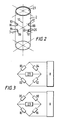
- Figure 1 represents a pipe structure such as a subsea riser having a gauge according to the present invention. Figure 2 represents a part of a bending bar according to the present invention showing the location for an orthogonal pair of internal strain gauge bridges and Figure 3 shows how these strain gauges may be connected in an electronic circuit. Figure 4 shows the locations of 24 strain gauges in a bending bar according to the present invention. Figure 5 shows an end view of the bending bar in Figure 4.
- In Figure 1 a pipe structure which was a 12 inch subsea riser (1) had a bending bar (2) attached by means of clamps (3). One end (4) of the bending bar was attached to the clamps (3) by a rigid mounting (5) so that it could not move in any direction with respect to the riser (1). The remainder of the bending bar was attached to the clamps (3) by flexible mountings (6) which allowed longitudinal movement along the axis (10) of the bar with respect to the riser (1). The mountings (6) were flexible metal plates which were free to bend to allow the bar to move along its axis (10). The bending bar (2) was in the form of a uniform hollow tube. Inside the bending bar strain gauges (not shown) were mounted on the inner surface (not shown) in groups of eight in positions (7) mid-way between the mountings (6). The strain gauges were connected to amplifiers (not shown) in a housing (11) and the amplifiers were connected to a power supply and data logger (not shown) by a cable (9).
- Figure 2 shows the configuration of one group of eight strain gauges (20) (R1 to R8) mounted on the inner surface (21) of the bending bar (2) at position (7) shown in Figure 1. The gauges were mounted as two orthogonal strain gauge bridges, each of which comprised diametrically opposed pairs of gauges in a common plane. The bridges were mounted orthogonally to each other so that a bend of the bar at that point could be measured as two orthogonal components, one in each of the planes of the bridges. Suitable strain gauges are HBM type: 3/350LY11 or Micromeasurement type NK-06-SO22H-50C.
- Figure 3 shows the electronic circuits for each of the two strain gauge bridges shown in Figure 2. The bridge circuits were connected to suitable power supplies (23) and amplifiers (8) such as Analog Devices 2431L or Technimeasure type SGA 708 which are combined power supplies and amplifiers.
- Figure 4 shows the positions of three groups (30, 31, 32) each of eight strain gauges (20) mounted inside a bending bar (2). Each group of eight strain gauges comprised a pair of orthogonally mounted strain gauge bridges each of which comprises two diametrically opposed pairs of gauges in a common plane. This arrangement used a total of 24 strain gauges (20). The orthogonal pairs of bridges were mounted at 30° intervals to each other as shown (reference planes X and Y are shown for clarity). To facilitate wiring for two of the sets (30, 32) of orthogonal pairs of bridges, the bridges were mounted at opposite ends of the arrangement. The longitudinal distance between the bridges was small relative to the radius of curvature of the bend of the riser to be measured. The bridges were mounted typically in positions (7) midway between the mountings (6) of the bar as shown in Figure 1 using a method similar to that described in Mechanical Engineering December, 1988 pages 35 to 46. On assembly, in order to accurately maintain the positional relationship between the 24 strain gauges, they were first accurately positioned on the back of a flexible printed circuit (not shown). Electrical links were made between the gauges and to the flexible printed circuit, the printed circuit electrically formed the bridge circuits for the gauges as in Figure 3 and extended as far as the amplifiers (8). The flexible printed circuit was wrapped around the outside of an insertion tool (not shown). The tool comprised a length of rubber tube on the outside of a metal tube. One end of the metal tube was sealed. The rubber tube was sealed to the metal tube at each end of the rubber (the rubber tube being shorter than the metal tube). The metal tube had holes which allow the rubber tube to be pressurised with gas through the open end of the metal tube. Normal strain gauge preparation was given to the inner surface of the bending bar and also to the gauges mounted on the flexible printed circuit. Adhesive was applied to both the gauges (20) and the inner surface of the bar. The flexible printed circuit mounted on the tool was inserted into the bar and the rubber tube pressurised to expand it and press the flexible printed circuit and the gauges onto the inner surface of the bar. After the adhesive had cured, the pressure was released from the tool and the tool was removed from the bar. Heat may also be applied to cure the adhesive. The output of the bend output amplifiers (8) was calibrated by subjecting the bending bar to know bends using a four point bending rig prior to attachment to the riser. The device was easily attached by a diver. In use, the bending bar bent in response to bending of the riser. Changes in resistance of the strain gauges due to bending of the bending bar were amplified by the bend output amplifiers to give the components of the bend for each bridge. From these, bending of the bending bar and hence the riser could be determined. From this, the bending stresses in the riser could be calculated using conventional techniques. By using more than two bridge pairs a degree of redundancy was introduced and the direction of the bend could be more accurately determined.
- Figure 5 shows an end view of the bending bar in Figure 4 to show the 30° interval between the planes of the strain gauge bridges.
Claims (11)
1. A gauge suitable for measuring bending of a structure, the gauge comprising a bending bar having means for attaching the bar to the structure and means for measuring bending of the bar, the attaching means being adapted to allow the bar to bend in response to bending of the structure, whereby measurment of bending of the bar enables bending of the structure to be determined.
2. A gauge according to claim 1 in which the attaching means comprises clamps with mountings, which in use allow at least part of the bar to move longitudinally along its axis with respect to the structure.
3. A gauge according to claim 1 or claim 2 in which the attaching means are adapted so that in use, part of the bar cannot move in any direction with respect to the structure.
4. A gauge according to any one of the preceeding claims in which the bar is hollow and the bend measuring means is mounted on the inner surface of the bar.
5. A gauge according to any one of the preceeding claims in which the bend measuring means comprises one or more strain measuring devices mounted on the bending bar.
6. A gauge according to claim 5 in which the strain measuring devices comprise strain gauges.
7. A gauge according to claim 6 in which the strain gauges are mounted as strain gauge bridges comprising four gauges mounted in opposed pairs.
8. A gauge according to claim 7 having a pair of stain gauge bridges orthogonal to each other.
9. A gauge according to claim 8 having three pairs of orthogonal gauge bridges.
10. A gauge substantially as hereinbefore described and with reference to the drawings.
11. A method of measuring the bending of a structure comprising attaching to the structure a gauge according to any one of the preceeding claims so that the bar bends in response to bending of the structure and measuring the bending of the bar so as to determine bending of the structure.
Applications Claiming Priority (2)
| Application Number | Priority Date | Filing Date | Title |
|---|---|---|---|
| GB8729061 | 1987-12-12 | ||
| GB878729061A GB8729061D0 (en) | 1987-12-12 | 1987-12-12 | Gauge |
Publications (1)
| Publication Number | Publication Date |
|---|---|
| EP0323019A1 true EP0323019A1 (en) | 1989-07-05 |
Family
ID=10628418
Family Applications (1)
| Application Number | Title | Priority Date | Filing Date |
|---|---|---|---|
| EP88310952A Ceased EP0323019A1 (en) | 1987-12-12 | 1988-11-21 | Gauge for measuring bending of structures |
Country Status (5)
| Country | Link |
|---|---|
| US (1) | US5065631A (en) |
| EP (1) | EP0323019A1 (en) |
| BR (1) | BR8806524A (en) |
| GB (1) | GB8729061D0 (en) |
| NO (1) | NO885441L (en) |
Cited By (3)
| Publication number | Priority date | Publication date | Assignee | Title |
|---|---|---|---|---|
| EP1840501A3 (en) * | 2006-03-28 | 2010-05-19 | 2H Offshore Engineering Ltd | Curvature sensor |
| WO2011046463A1 (en) * | 2009-10-15 | 2011-04-21 | Siemens Aktiengesellschaft | Fluid pipe and method for detecting a deformation on the fluid pipe |
| US10495437B2 (en) | 2014-12-02 | 2019-12-03 | Ge Oil & Gas Uk Limited | Angular displacement of flexible pipe |
Families Citing this family (28)
| Publication number | Priority date | Publication date | Assignee | Title |
|---|---|---|---|---|
| US5373123A (en) * | 1992-12-21 | 1994-12-13 | Otis Elevator Company | Electromagnetic gaging of elevator rails and other structures |
| US5483836A (en) * | 1994-10-13 | 1996-01-16 | U.S. Army Corps Of Engineers As Represented By The Secretary Of The Army | Device for measuring lateral deformations in material test specimens |
| CH692559A5 (en) * | 1998-09-16 | 2002-07-31 | S C A I M E S A | Sensor compressive stress. |
| CA2460290A1 (en) * | 2001-11-01 | 2003-05-08 | Bliss C. Carkhuff | Techniques for monitoring health of vessels containing fluids |
| DE10342479B4 (en) * | 2002-09-17 | 2016-03-31 | Harmonic Drive Systems Inc. | Torque detection device for shaft gear |
| GB0620944D0 (en) * | 2006-10-20 | 2006-11-29 | Insensys Ltd | Curvature measurement moving relative to pipe |
| US7891250B2 (en) * | 2007-04-04 | 2011-02-22 | American Air Liquide, Inc. | Method and apparatus to digitize pressure gauge information |
| JP5427343B2 (en) | 2007-04-20 | 2014-02-26 | 任天堂株式会社 | Game controller |
| JP5427346B2 (en) | 2007-10-05 | 2014-02-26 | 任天堂株式会社 | Load detection program, load detection device, load detection system, and load detection method |
| JP5080196B2 (en) | 2007-10-09 | 2012-11-21 | 任天堂株式会社 | Program, information processing apparatus, information processing system, and information processing method |
| JP4382844B2 (en) | 2007-10-31 | 2009-12-16 | 任天堂株式会社 | Weighting machine for adjustment and weighting method for adjustment |
| JP5361349B2 (en) | 2008-11-28 | 2013-12-04 | 任天堂株式会社 | Information processing apparatus, computer program, information processing system, and information processing method |
| JP5806443B2 (en) | 2008-12-26 | 2015-11-10 | 任天堂株式会社 | Biological information management system |
| JP5271121B2 (en) | 2009-03-09 | 2013-08-21 | 任天堂株式会社 | Information processing program, information processing apparatus, information processing system, and information processing method |
| JP5436909B2 (en) | 2009-03-30 | 2014-03-05 | 任天堂株式会社 | Information processing program, information processing apparatus, information processing system, and information processing method |
| JP5161182B2 (en) | 2009-09-28 | 2013-03-13 | 任天堂株式会社 | Information processing program and information processing apparatus |
| JP5610735B2 (en) | 2009-09-29 | 2014-10-22 | 任天堂株式会社 | Information processing program, information processing apparatus, information processing method, and information processing system |
| JP5496591B2 (en) | 2009-09-30 | 2014-05-21 | 任天堂株式会社 | Information processing program and information processing apparatus |
| KR100971916B1 (en) * | 2010-01-28 | 2010-07-23 | (주)효원엔지니어링 | Water pipe supporting structure for construction of smooth ground |
| KR101212615B1 (en) | 2010-05-17 | 2012-12-18 | (주)태성종합기술 | Apparatus for identifiable droop of pipe using tension |
| US8596137B2 (en) * | 2010-07-09 | 2013-12-03 | Alliant Techsystems Inc. | Methods, devices, and systems relating to a sensing device |
| CA2804642A1 (en) | 2010-09-24 | 2012-03-29 | Synthes Usa, Llc | Device for measuring the degree of bending of an intramedullary nail |
| WO2014016784A2 (en) * | 2012-07-24 | 2014-01-30 | Services Petroliers Schlumberger | Displacement sensor for subsea structures |
| US9228428B2 (en) * | 2012-12-26 | 2016-01-05 | General Electric Company | System and method for monitoring tubular components of a subsea structure |
| FR3030718B1 (en) * | 2014-12-18 | 2019-05-31 | Airbus Operations | DEVICE AND METHOD FOR MEASURING MOVEMENT BETWEEN TWO SUBSTANTIALLY COAXIAL PARTS, PREFERABLY FOR AN AIRCRAFT |
| PL3483579T3 (en) * | 2017-11-08 | 2022-12-19 | Nkt Hv Cables Ab | Method and system for fatigue-monitoring of a submarine cable in off-shore operations |
| GB2571748B (en) * | 2018-03-07 | 2022-11-23 | Bae Systems Plc | A method and system for measuring the bending of rowing oars |
| CN119574570B (en) * | 2024-12-23 | 2025-08-15 | 浙江大学 | Visual on-line measuring device for inner tube section distortion in diameter-variable metal tube bending process |
Citations (4)
| Publication number | Priority date | Publication date | Assignee | Title |
|---|---|---|---|---|
| US3621437A (en) * | 1970-06-05 | 1971-11-16 | Cutler Hammer Inc | Bolt-on strain gage transducer structure |
| US3914991A (en) * | 1973-07-24 | 1975-10-28 | Nasa | Strain gage mounting assembly |
| US4355307A (en) * | 1976-11-26 | 1982-10-19 | Beck Darrel R | Safety stress shutdown switch |
| EP0093298A1 (en) * | 1982-04-29 | 1983-11-09 | INTERATOM Gesellschaft mit beschränkter Haftung | Method and device for monitoring deformation of a pipe bend |
Family Cites Families (6)
| Publication number | Priority date | Publication date | Assignee | Title |
|---|---|---|---|---|
| US3411348A (en) * | 1966-06-30 | 1968-11-19 | W C Dillon & Company Inc | Electronic dynamometer |
| US3599479A (en) * | 1969-05-29 | 1971-08-17 | Ali Umit Kutsay | Strain gage |
| US4174628A (en) * | 1978-07-10 | 1979-11-20 | Shell Oil Company | Marine riser measuring joint |
| DE2927004A1 (en) * | 1979-07-04 | 1981-05-27 | Bayer Ag, 5090 Leverkusen | PENICILLANIC ACID 1,1-DIOXIDES, THEIR PRODUCTION AND THEIR USE AS MEDICINAL PRODUCTS AS MEDICINAL PRODUCTS |
| US4452087A (en) * | 1982-04-05 | 1984-06-05 | Antonio Nicholas F D | Pipeline monitoring system |
| GB2156519B (en) * | 1984-03-02 | 1987-11-04 | British Gas Corp | Vibratory wire strain gauge assemblies for underwater attachment |
-
1987
- 1987-12-12 GB GB878729061A patent/GB8729061D0/en active Pending
-
1988
- 1988-11-21 EP EP88310952A patent/EP0323019A1/en not_active Ceased
- 1988-12-07 NO NO88885441A patent/NO885441L/en unknown
- 1988-12-08 US US07/281,571 patent/US5065631A/en not_active Expired - Fee Related
- 1988-12-09 BR BR888806524A patent/BR8806524A/en unknown
Patent Citations (4)
| Publication number | Priority date | Publication date | Assignee | Title |
|---|---|---|---|---|
| US3621437A (en) * | 1970-06-05 | 1971-11-16 | Cutler Hammer Inc | Bolt-on strain gage transducer structure |
| US3914991A (en) * | 1973-07-24 | 1975-10-28 | Nasa | Strain gage mounting assembly |
| US4355307A (en) * | 1976-11-26 | 1982-10-19 | Beck Darrel R | Safety stress shutdown switch |
| EP0093298A1 (en) * | 1982-04-29 | 1983-11-09 | INTERATOM Gesellschaft mit beschränkter Haftung | Method and device for monitoring deformation of a pipe bend |
Non-Patent Citations (1)
| Title |
|---|
| PATENT ABSTRACTS OF JAPAN, Vol. 7, No. 73 (P-186)[1218], 25th March 1983; & JP-A- 58 002 601 (HITACHI DENSEN K.K.) 08-01-1983 * |
Cited By (3)
| Publication number | Priority date | Publication date | Assignee | Title |
|---|---|---|---|---|
| EP1840501A3 (en) * | 2006-03-28 | 2010-05-19 | 2H Offshore Engineering Ltd | Curvature sensor |
| WO2011046463A1 (en) * | 2009-10-15 | 2011-04-21 | Siemens Aktiengesellschaft | Fluid pipe and method for detecting a deformation on the fluid pipe |
| US10495437B2 (en) | 2014-12-02 | 2019-12-03 | Ge Oil & Gas Uk Limited | Angular displacement of flexible pipe |
Also Published As
| Publication number | Publication date |
|---|---|
| BR8806524A (en) | 1989-08-22 |
| US5065631A (en) | 1991-11-19 |
| NO885441L (en) | 1989-06-13 |
| NO885441D0 (en) | 1988-12-07 |
| GB8729061D0 (en) | 1988-01-27 |
Similar Documents
| Publication | Publication Date | Title |
|---|---|---|
| US5065631A (en) | Gauge for measuring bending of structures | |
| US5386724A (en) | Load cells for sensing weight and torque on a drill bit while drilling a well bore | |
| US5728953A (en) | Cable load sensing device | |
| EP3538856B1 (en) | Porch mounted variable reluctance measurement technology tendon tension monitoring system | |
| KR20160003088A (en) | Bipartite sensor array | |
| CN110082023A (en) | A kind of real-time monitoring for cable force device and monitoring method | |
| EP1840501B1 (en) | Curvature sensor | |
| CN115824075B (en) | A non-type enhanced sensitivity fiber Bragg grating strain sensor | |
| JPS62273423A (en) | Measured value detector | |
| US20140354974A1 (en) | Apparatus and Method for Monitoring the Mechanical Properties of Subsea Longitudinal Vertical Components in Offshore Drilling and Production Applications | |
| KR101682824B1 (en) | Thrust-torque sensor with strain gauge directly attached to stem | |
| JP2007205740A (en) | Inclinometer using FBG optical fiber sensor | |
| US20160326861A1 (en) | Apparatus and Method for Monitoring the Mechanical Properties of Subsea Longitudinal Vertical Components in Offshore Drilling and Production Applications | |
| JPS58173405A (en) | Extensometer | |
| US3481189A (en) | Strain gage measuring system | |
| US4607435A (en) | Temperature compensated extensometer | |
| CN112985310B (en) | A method for measuring the spatial angle of a dredger's rake pipe | |
| GB2284669A (en) | Determination of in situ stress in concrete | |
| US4084430A (en) | Load measurement | |
| KR20110002704A (en) | Cable type displacement measuring sensor | |
| KR20210047102A (en) | Mooring device | |
| KR19990024134A (en) | Micro Vibration Displacement | |
| RU2283483C1 (en) | Device for measuring tractive force | |
| JPS62220823A (en) | Base rock pressure detector | |
| EP1664667A1 (en) | Set for measuring the linear strain in materials |
Legal Events
| Date | Code | Title | Description |
|---|---|---|---|
| PUAI | Public reference made under article 153(3) epc to a published international application that has entered the european phase |
Free format text: ORIGINAL CODE: 0009012 |
|
| AK | Designated contracting states |
Kind code of ref document: A1 Designated state(s): DE FR GB IT NL |
|
| 17P | Request for examination filed |
Effective date: 19891219 |
|
| 17Q | First examination report despatched |
Effective date: 19910729 |
|
| STAA | Information on the status of an ep patent application or granted ep patent |
Free format text: STATUS: THE APPLICATION HAS BEEN REFUSED |
|
| 18R | Application refused |
Effective date: 19930211 |