EP0322843B1 - Can seamer - Google Patents
Can seamer Download PDFInfo
- Publication number
- EP0322843B1 EP0322843B1 EP88121686A EP88121686A EP0322843B1 EP 0322843 B1 EP0322843 B1 EP 0322843B1 EP 88121686 A EP88121686 A EP 88121686A EP 88121686 A EP88121686 A EP 88121686A EP 0322843 B1 EP0322843 B1 EP 0322843B1
- Authority
- EP
- European Patent Office
- Prior art keywords
- seaming
- chuck
- lever
- rotary cylinder
- seaming chuck
- Prior art date
- Legal status (The legal status is an assumption and is not a legal conclusion. Google has not performed a legal analysis and makes no representation as to the accuracy of the status listed.)
- Expired - Lifetime
Links
- 238000004826 seaming Methods 0.000 claims description 92
- 230000000694 effects Effects 0.000 description 1
- 239000007788 liquid Substances 0.000 description 1
- 238000004806 packaging method and process Methods 0.000 description 1
Images


Classifications
-
- B—PERFORMING OPERATIONS; TRANSPORTING
- B21—MECHANICAL METAL-WORKING WITHOUT ESSENTIALLY REMOVING MATERIAL; PUNCHING METAL
- B21D—WORKING OR PROCESSING OF SHEET METAL OR METAL TUBES, RODS OR PROFILES WITHOUT ESSENTIALLY REMOVING MATERIAL; PUNCHING METAL
- B21D51/00—Making hollow objects
- B21D51/16—Making hollow objects characterised by the use of the objects
- B21D51/38—Making inlet or outlet arrangements of cans, tins, baths, bottles, or other vessels; Making can ends; Making closures
- B21D51/44—Making closures, e.g. caps
-
- B—PERFORMING OPERATIONS; TRANSPORTING
- B21—MECHANICAL METAL-WORKING WITHOUT ESSENTIALLY REMOVING MATERIAL; PUNCHING METAL
- B21D—WORKING OR PROCESSING OF SHEET METAL OR METAL TUBES, RODS OR PROFILES WITHOUT ESSENTIALLY REMOVING MATERIAL; PUNCHING METAL
- B21D51/00—Making hollow objects
- B21D51/16—Making hollow objects characterised by the use of the objects
- B21D51/26—Making hollow objects characterised by the use of the objects cans or tins; Closing same in a permanent manner
- B21D51/30—Folding the circumferential seam
- B21D51/32—Folding the circumferential seam by rolling
-
- B—PERFORMING OPERATIONS; TRANSPORTING
- B65—CONVEYING; PACKING; STORING; HANDLING THIN OR FILAMENTARY MATERIAL
- B65B—MACHINES, APPARATUS OR DEVICES FOR, OR METHODS OF, PACKAGING ARTICLES OR MATERIALS; UNPACKING
- B65B59/00—Arrangements to enable machines to handle articles of different sizes, to produce packages of different sizes, to vary the contents of packages, to handle different types of packaging material, or to give access for cleaning or maintenance purposes
- B65B59/003—Arrangements to enable adjustments related to the packaging material
-
- B—PERFORMING OPERATIONS; TRANSPORTING
- B65—CONVEYING; PACKING; STORING; HANDLING THIN OR FILAMENTARY MATERIAL
- B65B—MACHINES, APPARATUS OR DEVICES FOR, OR METHODS OF, PACKAGING ARTICLES OR MATERIALS; UNPACKING
- B65B7/00—Closing containers or receptacles after filling
- B65B7/16—Closing semi-rigid or rigid containers or receptacles not deformed by, or not taking-up shape of, contents, e.g. boxes or cartons
- B65B7/28—Closing semi-rigid or rigid containers or receptacles not deformed by, or not taking-up shape of, contents, e.g. boxes or cartons by applying separate preformed closures, e.g. lids, covers
- B65B7/2842—Securing closures on containers
- B65B7/285—Securing closures on containers by deformation of the closure
- B65B7/2857—Securing closures on containers by deformation of the closure and the container rim
Definitions
- the present invention relates to a can seamer in which a can filled with liquid and having a can lid placed on the opening at the top is subjected to seaming work by means of seaming rolls and a seaming chuck.
- reference numeral 1 designates seaming rolls which are rotatably mounted on shafts 3 and 4, respectively, which are fixedly secured to a seaming lever 2.
- Reference numeral 5 designates a seaming chuck which is fixedly secured by a screw to the bottom of a rotary cylinder tube 6, and at the bottom of a knock-out rod 7 which extends through the rotary cylinder tube 6 in a vertically slidable manner, is fixedly secured a knock-out pad 9 by means of a screw 8.
- the knock-out pad 9 is projectable from a recessed portion 10 at the bottom of the above-mentioned seaming chuck 5.
- a more specific object of the present invention is to provide a can seamer which does not necessitate a long time for replacing seaming rolls and a seaming chuck when the can drum diameter and the can lid diameter are changed.
- a can seamer having the combination of features of the sole claim.
- the same seaming rolls as well as the same seaming chucks are pulled downwards as gripped by hands, then at the spline portion or the serration portion, the same rolls and chuck can be taken out integrally as connected via the connecting bracket.
- reference numeral 11 designates a first seaming roll
- numeral 12 designates a second seaming roll
- numeral 13 designates a seaming chuck
- Reference numeral 14 designates a seaming lever, which is inserted into a seaming roll shaft 15 via a spline (or serration) 15a so that it can be drawn out downwards.
- a spline (or serration) 15a so that it can be drawn out downwards.
- shafts 16 are fixed to the same seaming lever 14.
- the seaming rolls 11 and 12 are rotatably suspended at the center of the bottoms of the respective shafts 16 via bearings 18 fixed to the bottom portions of the shafts 16 by means of screws 17.
- the seaming chuck 13 is mounted via a spline (or serration) 22 to the bottom of a rotary cylinder 21 that is rotatably supported via a bearing 20 from a can seamer main body 19 so that the seaming chuck 13 can rotate integrally with the rotary cylinder 21.
- a knock-out rod 23 extends through the rotary cylinder 21 in a vertically slidable manner, and at the bottom of this rod 23 is fixed a knock-out pad 24 by means of a screw 25. The knock-out pad operates to be projected from a recess 26 at the bottom of the seaming chuck 13 to cause a packaging can subjected to a seaming work to be disengaged from the seaming chuck 13.
- Reference numeral 27 designates a connecting bracket which integrally connects the seaming lever 14 with the seaming chuck 13. More particularly, this connecting bracket 27 is connected with the seaming chuck 13 via flanges 28 provided on its outer circumference, also it is connected with the seaming lever 14 via rings 29, and these rings 29 are rotatably fixed by means of a lock nut 30 engaged with the connecting bracket 14.
- reference numeral 31 designates bolts for positioning the seaming chuck 13 in the vertical direction with respect to the rotary cylinder 21.
- a cam 35 is rotated about the center axis of the shaft 37 by means of a lever 36 and is pressed against the seaming roll shaft 15, and thereby drop of these members can be prevented.
- the mounting can be done within a short period by merely aligning the spline of the new seaming lever 14 with the spline 15a of the seaming roll shaft 15 and the spline of the new seaming chuck 13 with the spline 22 and pushing them up, because the spline diameters of the new members are identical to those of the old ones.
- Figs. 4 to 6 illustrate a second preferred embodiment of the present invention, in which a connecting bracket 27 is directly mounted to a can seamer main body 19 via a mounting bracket 41. More particularly, as shown in Fig. 5 which is a cross-section view taken along line C-C in Fig. 4, a seaming lever 14 and a seaming chuck 13 are rotatably mounted to the connecting bracket 27.
- the mounting bracket 41 is fixedly secured to the can seamer main body 19 by means of bolts 46, and at the outer circumferential portion of the same bracket 41 is mounted a pin 43 so as to be movable in its axial direction as biased by a spring 45 towards its innermost position.
- a knob 42 at the outer end of the pin 43 is pulled and rotated to make a transverse pin 44 projected from the pin 43 engaged with a projected portion of the mounting bracket 41, thereby the tip end of the pin 43 is held retreated, and then the mounting bracket 41 is pulled out downwards.
- the mounting bracket 41 is inserted under the above-mentioned condition, the tip end of the pin 43 is inserted into a tapered hole formed in one part of the bracket 41 to fix the mounting bracket 41 against vertical movement and rotation.
- the modified embodiment shown in Figs. 4 to 6 is not different in effects and advantages from the first embodiment shown in Figs. 1 to 3.
- the can seamer according to the present invention is constructed as described in detail above and in the can seamer the seaming rolls and the seaming chuck can be replaced simultaneously as integrated via the connecting bracket, various advantages can be realized such that replacement time can be shortened greatly as compared to the case where the seaming rolls and the seaming chuck are respectively separately replaced as is the case with the prior art, and that time for mutual fine adjustment of these members is quite unnecessary as compared to the case where these members are separately mounted and individually adjusted as is the case with the prior art.
Landscapes
- Engineering & Computer Science (AREA)
- Mechanical Engineering (AREA)
- Sealing Of Jars (AREA)
- Rigid Containers With Two Or More Constituent Elements (AREA)
- Stackable Containers (AREA)
Description
- The present invention relates to a can seamer in which a can filled with liquid and having a can lid placed on the opening at the top is subjected to seaming work by means of seaming rolls and a seaming chuck.
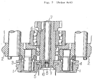
- One example the heretofore known can seamers will be explained with reference to Fig. 7. In this
figure reference numeral 1 designates seaming rolls which are rotatably mounted onshafts 3 and 4, respectively, which are fixedly secured to aseaming lever 2. Reference numeral 5 designates a seaming chuck which is fixedly secured by a screw to the bottom of arotary cylinder tube 6, and at the bottom of a knock-outrod 7 which extends through therotary cylinder tube 6 in a vertically slidable manner, is fixedly secured a knock-out pad 9 by means of a screw 8. The knock-out pad 9 is projectable from arecessed portion 10 at the bottom of the above-mentioned seaming chuck 5. - In the above-mentioned known can seamer in the prior art shown in Fig. 7, the
shafts 3 and 4 having theseaming rolls 1 mounted thereon and the seaming chuck 5 were separately fixed by screws to theseaming lever 2 and therotary cylinder tube 6, respectively. Accordingly, upon changing the can drum diameter and the can lid diameter, themounting shafts 3 and 4 having the seaming rolls mounted thereon and the seaming chuck 5 fixed to therotary cylinder tube 6, respectively, had to be replaced separately, and there were various problems such that since these members were fixed by screws and a large number of seaming rolls and seaming chucks were disposed in the seamer, a long time was necessitated for replacing these members, and moreover the relative adjustment of these members in the vertical direction as well as the adjustment in the horizontal direction necessitated a long time for realizing a high precision. - It is therefore one object of the present invention to provide an improved can seamer which is free from the above-mentioned shortcomings of the can seamers in the prior art.
- A more specific object of the present invention is to provide a can seamer which does not necessitate a long time for replacing seaming rolls and a seaming chuck when the can drum diameter and the can lid diameter are changed.
- According to the present invention, there is provided a can seamer having the combination of features of the sole claim.
- According to the present invention, in the case where it is necessary to replace the seaming rolls and the seaming chuck, if the same seaming rolls as well as the same seaming chucks are pulled downwards as gripped by hands, then at the spline portion or the serration portion, the same rolls and chuck can be taken out integrally as connected via the connecting bracket. Subsequently, in order to mount other seaming rolls and another seaming chuck having changed sizes, by merely pushing up the seaming rolls and the seaming chuck by hands with their respective splines (or serrations) aligned with the splines (or serrations) at the connecting portion, mounting of the seaming rolls and the seaming chuck can be achieved easily, and thereby the replacement by the new members having the changed size can be performed quickly.
- The above-mentioned and other objects and advantages of the present invention will become more apparent by reference to the following description of preferred embodiments of the invention taken in conjunction with the accompanying drawings.
- In the accompanying drawings:
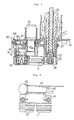
- Fig. 1 is a plan view showing a part of a can seamer according to one preferred embodiment of the present invention;
- Fig. 2 is a schematic partial side view as viewed in the direction of arrow A in Fig. 1;
- Fig. 3 is a cross-section view taken along line B-B in Fig. 1 as viewed in the direction of arrows;
- Fig 4 is a plan view showing a part of a can seamer according to another preferred embodiment of the present invention;
- Fig. 5 is a cross-section view taken along line C-C in Fig. 4 as viewed in the direction of arrows;
- Fig. 6 is a schematic partial side view as viewed in the direction of arrow D in Fig. 4; and
- Fig. 7 is a longitudinal cross-section view showing seaming rolls and a seaming chuck in a heretofore known can seamer.
- Now the present invention will be described in greater detail in connection with preferred embodiments of the invention illustrated in the accompanying drawings. In a first preferred embodiment of the present invention shown in Figs. 1 to 3,
reference numeral 11 designates a first seaming roll,numeral 12 designates a second seaming roll, andnumeral 13 designates a seaming chuck.Reference numeral 14 designates a seaming lever, which is inserted into aseaming roll shaft 15 via a spline (or serration) 15a so that it can be drawn out downwards. However, it is fixed to thesame shaft 15 so as to be able to rotate integrally therewith, and in addition,shafts 16 are fixed to thesame seaming lever 14. Theseaming rolls respective shafts 16 via bearings 18 fixed to the bottom portions of theshafts 16 by means of screws 17. On the other hand, theseaming chuck 13 is mounted via a spline (or serration) 22 to the bottom of arotary cylinder 21 that is rotatably supported via abearing 20 from a can seamermain body 19 so that theseaming chuck 13 can rotate integrally with therotary cylinder 21. In addition, a knock-outrod 23 extends through therotary cylinder 21 in a vertically slidable manner, and at the bottom of thisrod 23 is fixed a knock-outpad 24 by means of ascrew 25. The knock-out pad operates to be projected from arecess 26 at the bottom of theseaming chuck 13 to cause a packaging can subjected to a seaming work to be disengaged from theseaming chuck 13. -
Reference numeral 27 designates a connecting bracket which integrally connects theseaming lever 14 with theseaming chuck 13. More particularly, this connectingbracket 27 is connected with theseaming chuck 13 via flanges 28 provided on its outer circumference, also it is connected with theseaming lever 14 viarings 29, and theserings 29 are rotatably fixed by means of alock nut 30 engaged with the connectingbracket 14. In addition, reference numeral 31 designates bolts for positioning theseaming chuck 13 in the vertical direction with respect to therotary cylinder 21. Upon seaming a can, normally the can exerts a push-up force upon theseaming chuck 13, and so, an upward force is also exerted upon the seaming rolls which are connected with theseaming chuck 13 by means of the connectingbracket 27. However, in order to prevent the seaming rolls, the connecting bracket and the seaming chuck from dropping at the time when the can seaming is not effected, acam 35 is rotated about the center axis of theshaft 37 by means of alever 36 and is pressed against theseaming roll shaft 15, and thereby drop of these members can be prevented. - Now description will be made of the operation of the above-described can seamer. When it is necessary to replace the
seaming rolls seaming chuck 13 in accordance with change of the can lid diameter, after thelever 36 has been turned about theshaft 37 to separate thecam 35 from theseaming roll 15, theseaming rolls seaming chuck 13 are pulled down as gripped by hands, then since theseaming lever 14 and theseaming chuck 13 are integrally connected by the connectingbracket 27, theseaming lever 14 is disengaged from theseaming roll shaft 15 via thespline 15a, also theseaming chuck 13 is disengaged from therotary cylinder 21 via thespline 22, and thus they can be pulled down integrally by the intermediary of the connectingbracket 27. - Subsequently, in order to mount a
new seaming lever 14 havingseaming rolls new seaming chuck 13 of the changed size, the mounting can be done within a short period by merely aligning the spline of thenew seaming lever 14 with thespline 15a of theseaming roll shaft 15 and the spline of thenew seaming chuck 13 with thespline 22 and pushing them up, because the spline diameters of the new members are identical to those of the old ones. - Figs. 4 to 6 illustrate a second preferred embodiment of the present invention, in which a connecting
bracket 27 is directly mounted to a can seamermain body 19 via amounting bracket 41. More particularly, as shown in Fig. 5 which is a cross-section view taken along line C-C in Fig. 4, aseaming lever 14 and aseaming chuck 13 are rotatably mounted to the connectingbracket 27. In addition, themounting bracket 41 is fixedly secured to the can seamermain body 19 by means ofbolts 46, and at the outer circumferential portion of thesame bracket 41 is mounted a pin 43 so as to be movable in its axial direction as biased by aspring 45 towards its innermost position. - In the case where the
mounting bracket 41 and component parts integrally connected therewith are to be dismounted, aknob 42 at the outer end of the pin 43 is pulled and rotated to make atransverse pin 44 projected from the pin 43 engaged with a projected portion of themounting bracket 41, thereby the tip end of the pin 43 is held retreated, and then themounting bracket 41 is pulled out downwards. On the contrary, upon mounting these members, themounting bracket 41 is inserted under the above-mentioned condition, the tip end of the pin 43 is inserted into a tapered hole formed in one part of thebracket 41 to fix themounting bracket 41 against vertical movement and rotation. The modified embodiment shown in Figs. 4 to 6 is not different in effects and advantages from the first embodiment shown in Figs. 1 to 3. - Since the can seamer according to the present invention is constructed as described in detail above and in the can seamer the seaming rolls and the seaming chuck can be replaced simultaneously as integrated via the connecting bracket, various advantages can be realized such that replacement time can be shortened greatly as compared to the case where the seaming rolls and the seaming chuck are respectively separately replaced as is the case with the prior art, and that time for mutual fine adjustment of these members is quite unnecessary as compared to the case where these members are separately mounted and individually adjusted as is the case with the prior art.
Claims (1)
- A can seamer comprising
a first and a second seaming roll (11, 12) rotatably mounted to respective shafts (16),
a seaming lever (14) to which said shafts (16) are affixed,
a rotary cylinder (21) having a lower end portion, and
a seaming chuck (13) connected with said rotary cylinder (21),
characterized in that,
said seaming chuck (13) is mounted axially on said lower end portion of said rotary cylinder (21) by means of a spline or serration connection therebetween, such that said seaming chuck (13) is rotatable with said rotary cylinder (21),
a seaming roll shaft (15) having a lower end portion is provided,
said seaming lever (14) is mounted axially on said lower end portion of said seaming roll shaft (15) by means of a spline or serration connection therebetween, such that said seaming lever (14) is rotatable with said seaming roll shaft (15),
locking means (35, 43) are provided to prevent axial movement of said seaming rolls (11, 12) and said seaming chuck (13) and
a connecting bracket (27) is provided connecting said seaming lever (14) to said seaming chuck (13), such that said seaming lever (14) and seaming chuck, (13) are removable from and mountable on said seaming roll shaft (13) and said rotary cylinder (21), respectively, as a unit with said connecting bracket (27).
Applications Claiming Priority (4)
| Application Number | Priority Date | Filing Date | Title |
|---|---|---|---|
| JP33410987 | 1987-12-29 | ||
| JP334109/87 | 1987-12-29 | ||
| JP120756/88 | 1988-05-19 | ||
| JP63120756A JPH07110388B2 (en) | 1987-12-29 | 1988-05-19 | Can seamer |
Publications (2)
| Publication Number | Publication Date |
|---|---|
| EP0322843A1 EP0322843A1 (en) | 1989-07-05 |
| EP0322843B1 true EP0322843B1 (en) | 1992-05-06 |
Family
ID=26458285
Family Applications (1)
| Application Number | Title | Priority Date | Filing Date |
|---|---|---|---|
| EP88121686A Expired - Lifetime EP0322843B1 (en) | 1987-12-29 | 1988-12-27 | Can seamer |
Country Status (7)
| Country | Link |
|---|---|
| US (1) | US4961300A (en) |
| EP (1) | EP0322843B1 (en) |
| JP (1) | JPH07110388B2 (en) |
| KR (1) | KR920000237B1 (en) |
| AU (1) | AU598707B2 (en) |
| CA (1) | CA1311158C (en) |
| DE (1) | DE3870841D1 (en) |
Families Citing this family (13)
| Publication number | Priority date | Publication date | Assignee | Title |
|---|---|---|---|---|
| GB8825280D0 (en) * | 1988-10-28 | 1988-11-30 | Mb Group Plc | Seaming rolls |
| JP2799229B2 (en) * | 1990-07-25 | 1998-09-17 | 北海製罐株式会社 | Clearance setting mechanism between seaming cam lever and housing in double winder |
| US5157634A (en) * | 1990-10-23 | 1992-10-20 | International Business Machines Corporation | Dram having extended refresh time |
| US5320469A (en) * | 1991-10-30 | 1994-06-14 | Mitsubishi Jukogyo Kabushiki Kaisha | Can seamer |
| US5860782A (en) * | 1997-12-23 | 1999-01-19 | Abc Seamer Technologies, Inc. | Container seaming apparatus and methods |
| ITPR20070011A1 (en) * | 2007-03-01 | 2008-09-02 | Cft Packaging S P A | ROTARY SEWER |
| ITPR20070075A1 (en) | 2007-10-09 | 2009-04-10 | Cft Packaging S P A | ROTARY SEWER |
| US8757953B2 (en) * | 2009-07-07 | 2014-06-24 | Crown Packaging Technology, Inc. | Double seaming chuck-knockout |
| US9085026B2 (en) | 2009-07-07 | 2015-07-21 | Crown Packaging Technology, Inc. | High speed seaming assembly |
| US20120021882A1 (en) * | 2010-07-23 | 2012-01-26 | Reiner Leroy J | Pin and double profile roll assembly |
| CN104174782B (en) * | 2014-08-13 | 2016-02-03 | 舟山市普陀天海适用技术研究所 | A kind of annular seaming device |
| ITUB20159812A1 (en) * | 2015-12-30 | 2017-06-30 | Lyra Bearing S R L | ? IMPROVED ROLLINA? |
| US10195657B1 (en) | 2016-05-03 | 2019-02-05 | Norland International, Inc. | Servo-driven seamer assembly for sealing a container |
Family Cites Families (7)
| Publication number | Priority date | Publication date | Assignee | Title |
|---|---|---|---|---|
| US777784A (en) * | 1902-09-30 | 1904-12-20 | Crown Cork And Seal Co | Head for bottle-capping machines. |
| US1996381A (en) * | 1933-06-15 | 1935-04-02 | Paul H Lange | Seaming mechanism |
| US2152571A (en) * | 1937-09-30 | 1939-03-28 | Owens Illinois Glass Co | Closure applying apparatus |
| US2748733A (en) * | 1953-02-05 | 1956-06-05 | American Can Co | Seaming head |
| US4086747A (en) * | 1977-05-05 | 1978-05-02 | Aluminum Company Of America | Headset device for a capping machine |
| US4760725A (en) * | 1986-05-02 | 1988-08-02 | Ball Corporation | Spin flow forming |
| JP5412873B2 (en) | 2009-02-25 | 2014-02-12 | トヨタ自動車株式会社 | Semiconductor device and current measuring method of semiconductor device |
-
1988
- 1988-05-19 JP JP63120756A patent/JPH07110388B2/en not_active Expired - Lifetime
- 1988-12-22 AU AU27453/88A patent/AU598707B2/en not_active Ceased
- 1988-12-27 DE DE8888121686T patent/DE3870841D1/en not_active Expired - Lifetime
- 1988-12-27 EP EP88121686A patent/EP0322843B1/en not_active Expired - Lifetime
- 1988-12-29 CA CA000587238A patent/CA1311158C/en not_active Expired - Lifetime
- 1988-12-29 KR KR1019880017808A patent/KR920000237B1/en not_active Expired
- 1988-12-29 US US07/291,789 patent/US4961300A/en not_active Expired - Fee Related
Also Published As
| Publication number | Publication date |
|---|---|
| AU2745388A (en) | 1989-07-06 |
| CA1311158C (en) | 1992-12-08 |
| US4961300A (en) | 1990-10-09 |
| JPH01254332A (en) | 1989-10-11 |
| KR890009489A (en) | 1989-08-02 |
| AU598707B2 (en) | 1990-06-28 |
| EP0322843A1 (en) | 1989-07-05 |
| JPH07110388B2 (en) | 1995-11-29 |
| DE3870841D1 (en) | 1992-06-11 |
| KR920000237B1 (en) | 1992-01-10 |
Similar Documents
| Publication | Publication Date | Title |
|---|---|---|
| US4961300A (en) | Can seamer | |
| US5358369A (en) | Can seamer | |
| USRE33944E (en) | Printing machine cylinder holder arrangement | |
| US4823693A (en) | Printing cylinder sleeve application apparatus and method | |
| US4836563A (en) | Selftightening drill chuck | |
| US4735140A (en) | Coupling for a sheet fed rotary printing machine | |
| JPS63318204A (en) | Tool holder for automatic tool exchange | |
| JPH09123396A (en) | Printing cylinder sleeve exchange device in printing machine | |
| US4696209A (en) | Lathe having an integrated chuck | |
| US4357787A (en) | Spindle for capping machine | |
| US4422238A (en) | Shock absorber shroud cutting tool | |
| CN210339719U (en) | Paper roll fixing device of printing machine | |
| EP1358024B1 (en) | Seam adjusters | |
| CA1194347A (en) | Boring tool with coarse and fine adjustment | |
| US6206382B1 (en) | Equalizing power chuck | |
| EP0903228A2 (en) | Adjusting mechanism for ink forme rollers in a printing machine | |
| CA2319940A1 (en) | Adjustable tool holder apparatus | |
| US3736067A (en) | Reboring tool for brake spiders | |
| US5286119A (en) | Bearing play adjusting assembly | |
| JP3505206B2 (en) | Machine for cutting can lids | |
| EP0475621A2 (en) | Auxiliary equipment for removing parts installed on can end double-seaming machine or installing such parts thereon | |
| JPH05123797A (en) | Device for changing die for can seamer | |
| US2514502A (en) | Can body end flanger with axially adjustable cam and turret | |
| US2665525A (en) | Guide tube operating means for glass feeders | |
| JPH0478403B2 (en) |
Legal Events
| Date | Code | Title | Description |
|---|---|---|---|
| PUAI | Public reference made under article 153(3) epc to a published international application that has entered the european phase |
Free format text: ORIGINAL CODE: 0009012 |
|
| 17P | Request for examination filed |
Effective date: 19890124 |
|
| AK | Designated contracting states |
Kind code of ref document: A1 Designated state(s): CH DE FR GB IT LI NL |
|
| 17Q | First examination report despatched |
Effective date: 19900726 |
|
| GRAA | (expected) grant |
Free format text: ORIGINAL CODE: 0009210 |
|
| AK | Designated contracting states |
Kind code of ref document: B1 Designated state(s): CH DE FR GB IT LI NL |
|
| ITF | It: translation for a ep patent filed | ||
| ET | Fr: translation filed | ||
| REF | Corresponds to: |
Ref document number: 3870841 Country of ref document: DE Date of ref document: 19920611 |
|
| PLBE | No opposition filed within time limit |
Free format text: ORIGINAL CODE: 0009261 |
|
| STAA | Information on the status of an ep patent application or granted ep patent |
Free format text: STATUS: NO OPPOSITION FILED WITHIN TIME LIMIT |
|
| 26N | No opposition filed | ||
| PGFP | Annual fee paid to national office [announced via postgrant information from national office to epo] |
Ref country code: FR Payment date: 19951212 Year of fee payment: 8 |
|
| PGFP | Annual fee paid to national office [announced via postgrant information from national office to epo] |
Ref country code: GB Payment date: 19951218 Year of fee payment: 8 |
|
| PGFP | Annual fee paid to national office [announced via postgrant information from national office to epo] |
Ref country code: DE Payment date: 19951222 Year of fee payment: 8 |
|
| PGFP | Annual fee paid to national office [announced via postgrant information from national office to epo] |
Ref country code: NL Payment date: 19951230 Year of fee payment: 8 |
|
| PGFP | Annual fee paid to national office [announced via postgrant information from national office to epo] |
Ref country code: CH Payment date: 19960125 Year of fee payment: 8 |
|
| PG25 | Lapsed in a contracting state [announced via postgrant information from national office to epo] |
Ref country code: GB Effective date: 19961227 |
|
| PG25 | Lapsed in a contracting state [announced via postgrant information from national office to epo] |
Ref country code: LI Effective date: 19961231 Ref country code: CH Effective date: 19961231 |
|
| PG25 | Lapsed in a contracting state [announced via postgrant information from national office to epo] |
Ref country code: NL Effective date: 19970701 |
|
| REG | Reference to a national code |
Ref country code: CH Ref legal event code: PL |
|
| GBPC | Gb: european patent ceased through non-payment of renewal fee |
Effective date: 19961227 |
|
| PG25 | Lapsed in a contracting state [announced via postgrant information from national office to epo] |
Ref country code: FR Effective date: 19970829 |
|
| NLV4 | Nl: lapsed or anulled due to non-payment of the annual fee |
Effective date: 19970701 |
|
| PG25 | Lapsed in a contracting state [announced via postgrant information from national office to epo] |
Ref country code: DE Effective date: 19970902 |
|
| REG | Reference to a national code |
Ref country code: FR Ref legal event code: ST |
|
| PG25 | Lapsed in a contracting state [announced via postgrant information from national office to epo] |
Ref country code: IT Free format text: LAPSE BECAUSE OF NON-PAYMENT OF DUE FEES;WARNING: LAPSES OF ITALIAN PATENTS WITH EFFECTIVE DATE BEFORE 2007 MAY HAVE OCCURRED AT ANY TIME BEFORE 2007. THE CORRECT EFFECTIVE DATE MAY BE DIFFERENT FROM THE ONE RECORDED. Effective date: 20051227 |