EP0322347B1 - Drag bit with nozzles for drilling plastic formations - Google Patents
Drag bit with nozzles for drilling plastic formations Download PDFInfo
- Publication number
- EP0322347B1 EP0322347B1 EP88710035A EP88710035A EP0322347B1 EP 0322347 B1 EP0322347 B1 EP 0322347B1 EP 88710035 A EP88710035 A EP 88710035A EP 88710035 A EP88710035 A EP 88710035A EP 0322347 B1 EP0322347 B1 EP 0322347B1
- Authority
- EP
- European Patent Office
- Prior art keywords
- bit
- cutting surface
- blade
- drag bit
- drag
- Prior art date
- Legal status (The legal status is an assumption and is not a legal conclusion. Google has not performed a legal analysis and makes no representation as to the accuracy of the status listed.)
- Expired - Lifetime
Links
- 230000015572 biosynthetic process Effects 0.000 title claims description 26
- 238000005553 drilling Methods 0.000 title claims description 10
- 238000005755 formation reaction Methods 0.000 title description 21
- 238000005520 cutting process Methods 0.000 claims description 58
- 239000010432 diamond Substances 0.000 claims description 45
- 229910003460 diamond Inorganic materials 0.000 claims description 42
- 239000011435 rock Substances 0.000 claims description 14
- 238000000034 method Methods 0.000 claims description 13
- 239000012530 fluid Substances 0.000 claims description 12
- 229910052751 metal Inorganic materials 0.000 description 7
- 239000002184 metal Substances 0.000 description 7
- 241000237858 Gastropoda Species 0.000 description 6
- 239000012634 fragment Substances 0.000 description 6
- 239000011159 matrix material Substances 0.000 description 6
- 230000008595 infiltration Effects 0.000 description 5
- 238000001764 infiltration Methods 0.000 description 5
- OKTJSMMVPCPJKN-UHFFFAOYSA-N Carbon Chemical compound [C] OKTJSMMVPCPJKN-UHFFFAOYSA-N 0.000 description 4
- 230000009471 action Effects 0.000 description 3
- 238000013461 design Methods 0.000 description 3
- 229910002804 graphite Inorganic materials 0.000 description 3
- 239000010439 graphite Substances 0.000 description 3
- 238000000465 moulding Methods 0.000 description 3
- 230000000295 complement effect Effects 0.000 description 2
- 239000004576 sand Substances 0.000 description 2
- 230000032258 transport Effects 0.000 description 2
- UONOETXJSWQNOL-UHFFFAOYSA-N tungsten carbide Chemical compound [W+]#[C-] UONOETXJSWQNOL-UHFFFAOYSA-N 0.000 description 2
- 238000012800 visualization Methods 0.000 description 2
- 235000003934 Abelmoschus esculentus Nutrition 0.000 description 1
- 240000004507 Abelmoschus esculentus Species 0.000 description 1
- 235000015076 Shorea robusta Nutrition 0.000 description 1
- 244000166071 Shorea robusta Species 0.000 description 1
- 230000002730 additional effect Effects 0.000 description 1
- 230000004075 alteration Effects 0.000 description 1
- 229910052799 carbon Inorganic materials 0.000 description 1
- 239000004927 clay Substances 0.000 description 1
- 238000004891 communication Methods 0.000 description 1
- 238000010276 construction Methods 0.000 description 1
- 230000003247 decreasing effect Effects 0.000 description 1
- 230000009189 diving Effects 0.000 description 1
- 230000000694 effects Effects 0.000 description 1
- 238000009472 formulation Methods 0.000 description 1
- 238000002955 isolation Methods 0.000 description 1
- 239000000463 material Substances 0.000 description 1
- VNWKTOKETHGBQD-UHFFFAOYSA-N methane Chemical compound C VNWKTOKETHGBQD-UHFFFAOYSA-N 0.000 description 1
- 239000000203 mixture Substances 0.000 description 1
- 238000012986 modification Methods 0.000 description 1
- 230000004048 modification Effects 0.000 description 1
- 230000002093 peripheral effect Effects 0.000 description 1
- 230000008569 process Effects 0.000 description 1
- 238000010008 shearing Methods 0.000 description 1
- 239000007787 solid Substances 0.000 description 1
Images

Classifications
-
- E—FIXED CONSTRUCTIONS
- E21—EARTH OR ROCK DRILLING; MINING
- E21B—EARTH OR ROCK DRILLING; OBTAINING OIL, GAS, WATER, SOLUBLE OR MELTABLE MATERIALS OR A SLURRY OF MINERALS FROM WELLS
- E21B10/00—Drill bits
- E21B10/60—Drill bits characterised by conduits or nozzles for drilling fluids
- E21B10/602—Drill bits characterised by conduits or nozzles for drilling fluids the bit being a rotary drag type bit with blades
-
- E—FIXED CONSTRUCTIONS
- E21—EARTH OR ROCK DRILLING; MINING
- E21B—EARTH OR ROCK DRILLING; OBTAINING OIL, GAS, WATER, SOLUBLE OR MELTABLE MATERIALS OR A SLURRY OF MINERALS FROM WELLS
- E21B10/00—Drill bits
- E21B10/46—Drill bits characterised by wear resisting parts, e.g. diamond inserts
- E21B10/56—Button-type inserts
- E21B10/567—Button-type inserts with preformed cutting elements mounted on a distinct support, e.g. polycrystalline inserts
- E21B10/5671—Button-type inserts with preformed cutting elements mounted on a distinct support, e.g. polycrystalline inserts with chip breaking arrangements
-
- E—FIXED CONSTRUCTIONS
- E21—EARTH OR ROCK DRILLING; MINING
- E21B—EARTH OR ROCK DRILLING; OBTAINING OIL, GAS, WATER, SOLUBLE OR MELTABLE MATERIALS OR A SLURRY OF MINERALS FROM WELLS
- E21B10/00—Drill bits
- E21B10/46—Drill bits characterised by wear resisting parts, e.g. diamond inserts
- E21B10/56—Button-type inserts
- E21B10/567—Button-type inserts with preformed cutting elements mounted on a distinct support, e.g. polycrystalline inserts
- E21B10/5673—Button-type inserts with preformed cutting elements mounted on a distinct support, e.g. polycrystalline inserts having a non planar or non circular cutting face
Definitions
- the invention relates to a drag bit for drilling a borehole in an earth formation as set forth in the pre-characterizing portion of claim 1.
- Drilling in shales or plastic formations with a drag bit has always been difficult.
- the shale, under pressure and in contact with hydraulics, tends to act like a sticky bubble-gum-like mass, sometimes referred to as gumbo, which balls and clogs the bit. Once the bit balls up, it ceases to cut effectively.
- GB-A-2 181 173 shows a bladed drag bit of the type referred to with a plurality of cutters on each blade in combination with a nozzle which creates a vortex flow having a peripheral stream extending across the cutting elements and exiting into a gage region.
- a proportion of the drilling fluid is allowed to escape from the central portion of the vortex through a circular exit passage extending azimuthally through the blade of the bit to open into an exit channel in the gage region.
- the cutters are spaced cutters and the nozzle is azimuthally disposed in front of the blade. This does not provide for a directed hydraulic impingement on the chips effectively preventing balling up the bit when drilling in plastic formations.
- EP-A-233 737 shows a bladed drag bit of a similar construction including discharge nozzles arranged in front of the blades and directing fluid against the formation in advance of the cutting elements. Such a direction of fluid tends to remove cuttings from the formation prior to the cutting action of the cutting elements, but does not effectively prevent adhesion of chips to the cutting surface.
- the invention is a drag bit comprising the features of claim 1.
- the invention is further a method of preventing bit balling as claimed in claim 14. Further embodiments of the drag bit are characterized in claims 2-13 and of the method in claims 15-18.
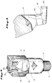
- Figure 1 is a perspective view of a completed drag bit incorporating the invention.
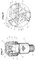
- Figure 2 is a diagrammatic plot sketch of the drill bit illustrated in Figure 1.
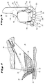
- Figure 3 is a diagrammatic profile of one of the cutting blades of the bit illustrated in Figures 1 and 2.
- Figure 4 is a highly diagrammatic partial cross-sectional view in enlarged scale illustrating the cutting and hydraulic action of one blade of the invention.
- Figure 5 is a perspective illustration of an alternative embodiment of the bit using half-round diamond cutters in the blade.
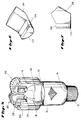
- Figure 6 is a perspective view in enlarged scale of one of the cutting slugs in the bit of Figure 5 shown in isolation of the bit.
- Figure 7 is a side view of the cutter slug of Figure 6.
- Figure 8 is a perspective illustration of another embodiment of the invention where the cutting slugs are provided with rectangular diamond faces.
- Figure 10 is a perspective illustration of yet another embodiment of the invention wherein triangular diamond faces are combined on the blade of a bit made according to the invention.
- a drag bit having a cutting face formed of a plurality of generally radially extending open arched blades.
- Each arched blade is provided with a cutting face and defines a cavity beneath the arch to the bit body.
- the cutting elements on the arched blade may include a plurality of synthetic polycrystalline diamonds which are cut, sized and shaped to conformally fit with each other so as to present a substantially diamond-only surface as a cutting surface of the bit.
- Hydraulic nozzles are defined in the bit body beneath and azimuthally behind the arches formed by each blade. The nozzles direct hydraulic flow across the cavity under the arch and across each portion of the cutting face on the arch.
- FIG 1 is a perspective illustration of a completed drag bit of the preferred embodiment fabricated through molding according to the invention using conventional metal matrix infiltration methodology.
- Drag bit 10 is characterized by a threaded portion 12 on the upper end of the shank (inverted in Figure 1 for ease of visualization). Threaded portion 12 is integral with shank 14 and shank 14 is integral with bit body 16.
- Bit body 16 is comprised of gage 18 and, in the illustrated embodiment, three blades 20. The number of blades is not material to the invention.
- each blade 20 is a plurality of synthetic polycrystalline diamond slug cutters 22 formed on the top of the arch comprised by blade 20. Cutters 22 extend from the center of bit 10 to its gage 18. Each blade forms a web characterized by an open cavity 24. Between blades 20 is an open space which forms a large open waterway 26 and face junk slot 28. The demarcation between waterway 26 and face junk slot 28 is somewhat arbitrary, but face junk slot 28 is generally the region adjacent the face 30 of bit body 16 and proximate the lower portion of waterway 26.
- Face junk slot 28 communicates with upper junk slot 32 which in turn extends to the upper part of the gage (again Figure 1 being inverted for ease of visualization, necessarily has upper junk slot 32 depicted below face junk slot 28 and waterway 26 in the depiction of Figure 1).
- Gages 18 also includes a plurality of longitudinal broaches 34 and ribs bearing gage diamond kickers 36. Kickers 36 are typically comprised of embedded natural diamonds or fragments of worn synthetic diamonds.
- each cavity 24 In the bottom of each cavity 24 are one or more nozzles 38 which direct hydraulic fluid from behind and upwardly across the face of cutters 22.
- the position of nozzles 38, cutters 22, blades 20 and waterways 26 can be better understood and visualized by now turning to the plot sketch of Figure 2.
- the plot sketch is a diagrammatic plan view of bit 10 of Figure 1.
- cutters 22 are compax cutters which typically are comprised of a polycrystalline synthetic diamond table 40, mounted, bonded or otherwise fixed to a metallic backing slug 42 which in turn is set within a cutter body 44 manufactured as part of the infiltration molding process. It is to be expressly understood that many other types of cutting elements or diamond cutters, e.g.
- each diamond table 40 is in the shape of a generally circular disc approximately one inch or more in diameter. It is also contemplated that fractions of a circular cutter may be used, such as half circular cutting elements. As will be described below, many other types, shapes and sizes of cutters may be employed according to the invention without departing from its scope.
- each of the primary cutters 22 overlaps with at least one adjacent cutter.
- a series of cutters 22 forms a three-dimensional arch as depicted in Figure 1, and as more simply and graphically depicted in the profile sketch of one of blades 20 in Figure 3.
- a first cutter denoted by reference numeral 22a as shown in Figure 3, is disposed near the apex portion of blade 20. It is a full circle.
- the next adjacent cutter 22b has been moon-cut so that it fits cutter 22a in a complementary manner and so that diamond tables 40 of cutters 22a and 22b are seen and act as a single diamond-only face. It should be noted that little or no matrix metal of bit 10 is presented to the rock formation in the proximity of the cutting blade.
- the next two adjacent cutters also denoted by reference numeral 22b, have the same complementary fit as cutter 22b which is adjacent to cutter 22a. Cutters 22c are also moon-cut to provide a complimentary fit.
- gage cutter 54 there are four cutters 22c which complete the diamond arch on web 20.
- the radial outermost cutter 22c extends radially from the longitudinal center of bit 10 to the gage diameter.
- Further gage definition is provided by a smaller diamond slug cutter 54 placed above the radial outermost cutter 22c which depicted below cutter 22c in Figure 3.
- gage cutter 54 is rotated azimuthally outward or side raked.
- Additional gage definition and protection are provided by similar small slug cutters 56 which are azimuthally displaced behind the arch of primary cutters 22a-22c again as best depicted in Figure 2.
- Figure 3 shows that such supplementary cutters 56 longitudinally overlap the radial outermost cutter 22c and its corresponding gage cutter 54.
- the cutter placement as just described is repeated three times in the bit, once for each blade 20, thereby providing a triple redundancy of cutters and cutting action.
- the degree of redundancy could of course be increased or decreased according to the number of blades used.
- Blade 20 is particularly characterized as depicted in Figure 3 as forming an open web characterized by a cavity 24 which underlies the arch of primary cutters 22a-22c. As shown in Figure 1, cavity 24 is completely open allowing free communication through each blade. However, disposed in the bottom of each blade is one or more nozzles 38 which are best depicted in Figure 2. Nozzles 38 are placed in the base portion 58 of the web best seen in Figure 3 which defines cavity 24 and behind the arch formed by cutters 22a-22c. In the illustrated embodiment, two sets of nozzles are provided for each blade 20.
- Nozzle 38a for example, provides a directed flow as symbolically denoted by arrow 60 which fans out from behind, down and then across the diamond tables 40 of cutters 22b-22c from approximately the midpoint to the gage end of the arch of cutters.
- Nozzle 38b similarly provides a directed flow, as symbolically denoted by arrow 62, across cutters 22a-22b from the midpoint to the apex of the arch of cutters.
- the hydraulic flow and its coaction with chip removal is best depicted in connection with Figure 4.
- Figure 4 is a diagrammatic cross-sectional view taken through cavity 24 of one of blades 20 as the bit is cutting into a formation 64.
- the primary cone of hydraulic flow is symbolically depicted as cone 66.
- the flow is ejected by nozzle 38 through cavity 24 downwardly and from behind cutters 22a. Chips being gouged from formation 64 are extruded upwardly across the face of diamond table 40 of cutter 22 and caught at their upper edge by the hydraulic flow contained within and adjacent to cone 66.
- the hydraulic flow peels chip 68 away from the face of diamond table 40.
- chip 68 becomes of such a size that it separates from formation 64 and is transported by the hydraulic flow into waterways 26, face junk slots 38 and junk slots 32.
- chips are entrained in the hydraulic flow up the borehole and carried to the well surface.
- chip 68 only contacts the cutting faces of diamond tables 40 and no other portion of the bit is presented for impact or diving contact with chips 68.
- chips 68 are exposed and impacted by hydraulic flow 66 from behind cutters 22. Cavities 24 are believed to act as chip breakers and to allow large chips 68 to be broken into smaller, more manageable pieces at the bit crown.
- the open design of bit 10 also allows a great deal of chip dynamics and turbulence to be created at the bit crown at the expense of a very limited amount of hydraulic volume.
- bit 10 is able to operate at lower hydraulic volumes and pressures and to tolerate a degree of plasticity in formations that would not otherwise be possible with cutter designs allowed or permitted greater impact between chips 68 and noncutting surfaces of bit 10. Chips 68, almost regardless of their plasticity or stickiness, have very little opportunity to contact or adhere to any surface of the bit before being broken up, pressure relieved, hydrated and carried away.
- bit 10 is manufactured using conventional metal matrix infiltration techniques.
- a metal blank body serves as the core of the bit, to which the blades are attached and around which the metal matrix is infiltrated.
- the blank has a generally cylindrical form comprised of a base portion which is machined at its lower end.
- bit blank once assembled, is inserted into a conventional graphite mold (not shown) together with a number of additional carbon and sand pieces which will define cavity 24, waterways 26, face junk slot 28 and junk slot 32 among other details of the bit face. Cutters 22 will be milled or defined into the bottom of the graphite mold, and the bit blank, as described with its various carbon pieces, is aligned within the bit mold relative to the cutter blanks and other bit face features set up within the mold.
- dummy blanks will be placed within the mold in place of the cutting slugs and the diamond tables. After the bit is fabricated, the dummy slugs will be removed and the diamond compax slugs may then be brazed or otherwise secured to the bit at a lower temperature than the infiltration temperature, which lower temperature will not degrade the diamond.
- the diamond cutters may be directly furnaced into the bit as the metal matrix is infiltrated around the bit blank.
- FIG. 5 a bit, generally denoted by reference numeral 200, is depicted wherein a plurality of semicircular diamond tables 210, which are comprised of slug cutters 202 which are made from cutters of the first embodiment which have been cut in half, are used to form the cutting elements in the blade arch.
- This allows relative inversion of the cutters along the gage of bit 200, as exemplified by cutter 204 as compared to cutters 210 to enhance gage definition.
- cutter 202 could be formed on tungsten carbide slugs 206 carrying a tungsten carbide backing 208 behind diamond table 210.
- a side view of slug 206 is depicted in Figure 7 and a perspective view is shown in Figure 6.
- FIGS 8 and 9 Yet another embodiment is shown in Figures 8 and 9 wherein rectangular diamond tables are laser cut from large cylindrical discs to provide a diamond cutting bar 302 of bit 300.
- diamond plates 304 are covered with diamond plates 304 in a mosaic or tile pattern as best depicted in the cross-sectional view shown in Figure 9 of one of the blades depicted in Figure 8.
- FIG. 10 Yet another embodiment may be devised as shown in the perspective view of figure 10 wherein the diamond tables of the slug cutters are formed or cut into a triangular shape to comprise cutters 402 of bit 400. Again, the only surface of the blade which is substantially exposed as a cutting surface is a diamond-only surface and no opportunity is provided to the plastic chips to adhere to any other surface of the bit.
Landscapes
- Engineering & Computer Science (AREA)
- Life Sciences & Earth Sciences (AREA)
- Mining & Mineral Resources (AREA)
- Geology (AREA)
- Mechanical Engineering (AREA)
- Physics & Mathematics (AREA)
- Environmental & Geological Engineering (AREA)
- Fluid Mechanics (AREA)
- General Life Sciences & Earth Sciences (AREA)
- Geochemistry & Mineralogy (AREA)
- Chemical & Material Sciences (AREA)
- Crystallography & Structural Chemistry (AREA)
- Earth Drilling (AREA)
Description
- The invention relates to a drag bit for drilling a borehole in an earth formation as set forth in the pre-characterizing portion of claim 1.
- Drilling in shales or plastic formations with a drag bit has always been difficult. The shale, under pressure and in contact with hydraulics, tends to act like a sticky bubble-gum-like mass, sometimes referred to as gumbo, which balls and clogs the bit. Once the bit balls up, it ceases to cut effectively.
- GB-A-2 181 173 shows a bladed drag bit of the type referred to with a plurality of cutters on each blade in combination with a nozzle which creates a vortex flow having a peripheral stream extending across the cutting elements and exiting into a gage region. To enhance the vortex flow a proportion of the drilling fluid is allowed to escape from the central portion of the vortex through a circular exit passage extending azimuthally through the blade of the bit to open into an exit channel in the gage region. However, the cutters are spaced cutters and the nozzle is azimuthally disposed in front of the blade. This does not provide for a directed hydraulic impingement on the chips effectively preventing balling up the bit when drilling in plastic formations.
- EP-A-233 737 shows a bladed drag bit of a similar construction including discharge nozzles arranged in front of the blades and directing fluid against the formation in advance of the cutting elements. Such a direction of fluid tends to remove cuttings from the formation prior to the cutting action of the cutting elements, but does not effectively prevent adhesion of chips to the cutting surface.
- While many of the prior art attemps have been successful in one degree or another, efficient drilling rates have always been difficult to achieve consistently in all types of plastic formations, with all types of hydraulic formulations and in all types of drilling conditions.
- Therefore, what is needed is a bit design for use in shale or plastic formations which is highly efficient in a broad range of conditions and environments.
- The invention is a drag bit comprising the features of claim 1. The invention is further a method of preventing bit balling as claimed in
claim 14. Further embodiments of the drag bit are characterized in claims 2-13 and of the method in claims 15-18. - As a result, plastic rock formations and other formations tending to ball and clog the bit are efficiently cut in a wide variety of conditions. The fluid flow from a position azimuthally behind the cutting surfaces of the cutters as defined by normal rotation of the bit when drilling tends to peel adhevise chips from the cutters or avoid adhesion of the plastic rock formation fragments to the bit by impinging on the azimuthally rear surface of the fragments of the plastic formation as the fragments clear the cutting face. The fluid flow from behind the cutters tends as an additional effect to break the cuttings and to remove the broken fragments from the proximity of the bit by hydraulic transport.
- Turn now to the following drawings of the invention wherein like elements are referenced by like numerals.
- Figure 1 is a perspective view of a completed drag bit incorporating the invention.
- Figure 2 is a diagrammatic plot sketch of the drill bit illustrated in Figure 1.
- Figure 3 is a diagrammatic profile of one of the cutting blades of the bit illustrated in Figures 1 and 2.
- Figure 4 is a highly diagrammatic partial cross-sectional view in enlarged scale illustrating the cutting and hydraulic action of one blade of the invention.
- Figure 5 is a perspective illustration of an alternative embodiment of the bit using half-round diamond cutters in the blade.
- Figure 6 is a perspective view in enlarged scale of one of the cutting slugs in the bit of Figure 5 shown in isolation of the bit.
- Figure 7 is a side view of the cutter slug of Figure 6.
- Figure 8 is a perspective illustration of another embodiment of the invention where the cutting slugs are provided with rectangular diamond faces.
- Figure 9 is a partial diagrammatic cross-sectional view of one blade of the bit of Figure 8.
- Figure 10 is a perspective illustration of yet another embodiment of the invention wherein triangular diamond faces are combined on the blade of a bit made according to the invention.
- Turn now to the following detailed description in which like elements are referenced by like numerals.
- An improved bit and method for cutting plastic and sticky formations, which tend to cause bit balling, is provided by a drag bit having a cutting face formed of a plurality of generally radially extending open arched blades. Each arched blade is provided with a cutting face and defines a cavity beneath the arch to the bit body. The cutting elements on the arched blade may include a plurality of synthetic polycrystalline diamonds which are cut, sized and shaped to conformally fit with each other so as to present a substantially diamond-only surface as a cutting surface of the bit. Hydraulic nozzles are defined in the bit body beneath and azimuthally behind the arches formed by each blade. The nozzles direct hydraulic flow across the cavity under the arch and across each portion of the cutting face on the arch. As a result, when cutting, only a diamond surface is provided for shearing the rock formation or contacting with velocity any portion of the plastic rock formation. Once the rock chip is exuded upwardly across the diamond face of the cutter, it is subjected to a directed hydraulic flow which peels the chip from the diamond face and transports it into the open cavity defined underneath the arched blade. The cavities under the arched blade freely communicate with a plurality of large open waterways and junk slots. Large plastic fragments may then be cut, peeled from the face of the diamond cutters, and flushed through the waterways up the junk slots.
- Figure 1 is a perspective illustration of a completed drag bit of the preferred embodiment fabricated through molding according to the invention using conventional metal matrix infiltration methodology.
Drag bit 10 is characterized by a threadedportion 12 on the upper end of the shank (inverted in Figure 1 for ease of visualization). Threadedportion 12 is integral withshank 14 andshank 14 is integral with bit body 16. Bit body 16 is comprised ofgage 18 and, in the illustrated embodiment, threeblades 20. The number of blades is not material to the invention. - As shown in Figures 1 and 3, on each
blade 20 is a plurality of synthetic polycrystallinediamond slug cutters 22 formed on the top of the arch comprised byblade 20.Cutters 22 extend from the center ofbit 10 to itsgage 18. Each blade forms a web characterized by anopen cavity 24. Betweenblades 20 is an open space which forms a largeopen waterway 26 andface junk slot 28. The demarcation betweenwaterway 26 andface junk slot 28 is somewhat arbitrary, butface junk slot 28 is generally the region adjacent theface 30 of bit body 16 and proximate the lower portion ofwaterway 26.Face junk slot 28 communicates withupper junk slot 32 which in turn extends to the upper part of the gage (again Figure 1 being inverted for ease of visualization, necessarily hasupper junk slot 32 depicted belowface junk slot 28 andwaterway 26 in the depiction of Figure 1).Gages 18 also includes a plurality oflongitudinal broaches 34 and ribs bearinggage diamond kickers 36.Kickers 36 are typically comprised of embedded natural diamonds or fragments of worn synthetic diamonds. - In the bottom of each
cavity 24 are one ormore nozzles 38 which direct hydraulic fluid from behind and upwardly across the face ofcutters 22. The position ofnozzles 38,cutters 22,blades 20 andwaterways 26 can be better understood and visualized by now turning to the plot sketch of Figure 2. The plot sketch is a diagrammatic plan view ofbit 10 of Figure 1. In the illustrated embodiment,cutters 22 are compax cutters which typically are comprised of a polycrystalline synthetic diamond table 40, mounted, bonded or otherwise fixed to ametallic backing slug 42 which in turn is set within acutter body 44 manufactured as part of the infiltration molding process. It is to be expressly understood that many other types of cutting elements or diamond cutters, e.g. natural diamond thermally stable polycristalline diamond or bonded stud cutters, could be substituted without departing from the spirit and scope of the invention. In the illustrated embodiment, each diamond table 40 is in the shape of a generally circular disc approximately one inch or more in diameter. It is also contemplated that fractions of a circular cutter may be used, such as half circular cutting elements. As will be described below, many other types, shapes and sizes of cutters may be employed according to the invention without departing from its scope. - As graphically depicted in Figure 2, each of the
primary cutters 22 overlaps with at least one adjacent cutter. A series ofcutters 22 forms a three-dimensional arch as depicted in Figure 1, and as more simply and graphically depicted in the profile sketch of one ofblades 20 in Figure 3. A first cutter, denoted byreference numeral 22a as shown in Figure 3, is disposed near the apex portion ofblade 20. It is a full circle. However, the nextadjacent cutter 22b has been moon-cut so that it fitscutter 22a in a complementary manner and so that diamond tables 40 ofcutters bit 10 is presented to the rock formation in the proximity of the cutting blade. The next two adjacent cutters, also denoted byreference numeral 22b, have the same complementary fit ascutter 22b which is adjacent tocutter 22a.Cutters 22c are also moon-cut to provide a complimentary fit. - Returning to Figure 3, it can be seen that there are four
cutters 22c which complete the diamond arch onweb 20. The radialoutermost cutter 22c extends radially from the longitudinal center ofbit 10 to the gage diameter. Further gage definition is provided by a smallerdiamond slug cutter 54 placed above the radialoutermost cutter 22c which depicted belowcutter 22c in Figure 3. As better seen in the plot sketch of Figure 2,gage cutter 54 is rotated azimuthally outward or side raked. Additional gage definition and protection are provided by similarsmall slug cutters 56 which are azimuthally displaced behind the arch ofprimary cutters 22a-22c again as best depicted in Figure 2. Figure 3 shows that suchsupplementary cutters 56 longitudinally overlap the radialoutermost cutter 22c and its correspondinggage cutter 54. - The cutter placement as just described is repeated three times in the bit, once for each
blade 20, thereby providing a triple redundancy of cutters and cutting action. The degree of redundancy could of course be increased or decreased according to the number of blades used. -
Blade 20 is particularly characterized as depicted in Figure 3 as forming an open web characterized by acavity 24 which underlies the arch ofprimary cutters 22a-22c. As shown in Figure 1,cavity 24 is completely open allowing free communication through each blade. However, disposed in the bottom of each blade is one ormore nozzles 38 which are best depicted in Figure 2.Nozzles 38 are placed in thebase portion 58 of the web best seen in Figure 3 which definescavity 24 and behind the arch formed bycutters 22a-22c. In the illustrated embodiment, two sets of nozzles are provided for eachblade 20.Nozzle 38a, for example, provides a directed flow as symbolically denoted byarrow 60 which fans out from behind, down and then across the diamond tables 40 ofcutters 22b-22c from approximately the midpoint to the gage end of the arch of cutters.Nozzle 38b similarly provides a directed flow, as symbolically denoted byarrow 62, acrosscutters 22a-22b from the midpoint to the apex of the arch of cutters. The hydraulic flow and its coaction with chip removal is best depicted in connection with Figure 4. - Figure 4 is a diagrammatic cross-sectional view taken through
cavity 24 of one ofblades 20 as the bit is cutting into aformation 64. The primary cone of hydraulic flow is symbolically depicted ascone 66. The flow is ejected bynozzle 38 throughcavity 24 downwardly and from behindcutters 22a. Chips being gouged fromformation 64 are extruded upwardly across the face of diamond table 40 ofcutter 22 and caught at their upper edge by the hydraulic flow contained within and adjacent tocone 66. The hydraulic flow peelschip 68 away from the face of diamond table 40. Ultimatelychip 68 becomes of such a size that it separates fromformation 64 and is transported by the hydraulic flow intowaterways 26, facejunk slots 38 andjunk slots 32. The chips are entrained in the hydraulic flow up the borehole and carried to the well surface. According to the invention,chip 68 only contacts the cutting faces of diamond tables 40 and no other portion of the bit is presented for impact or diving contact withchips 68. Furthermore, chips 68 are exposed and impacted byhydraulic flow 66 from behindcutters 22.Cavities 24 are believed to act as chip breakers and to allowlarge chips 68 to be broken into smaller, more manageable pieces at the bit crown. The open design ofbit 10 also allows a great deal of chip dynamics and turbulence to be created at the bit crown at the expense of a very limited amount of hydraulic volume. Therefore, bit 10 is able to operate at lower hydraulic volumes and pressures and to tolerate a degree of plasticity in formations that would not otherwise be possible with cutter designs allowed or permitted greater impact betweenchips 68 and noncutting surfaces ofbit 10.Chips 68, almost regardless of their plasticity or stickiness, have very little opportunity to contact or adhere to any surface of the bit before being broken up, pressure relieved, hydrated and carried away. - The overall geometry and operation of
bit 10 of the invention now having been described, consider the methodology wherein a bit according to the illustrated embodiment is manufactured. As first stated,bit 10 is manufactured using conventional metal matrix infiltration techniques. A metal blank body serves as the core of the bit, to which the blades are attached and around which the metal matrix is infiltrated. As known in the art the blank has a generally cylindrical form comprised of a base portion which is machined at its lower end. - The bit blank, once assembled, is inserted into a conventional graphite mold (not shown) together with a number of additional carbon and sand pieces which will define
cavity 24,waterways 26, facejunk slot 28 andjunk slot 32 among other details of the bit face.Cutters 22 will be milled or defined into the bottom of the graphite mold, and the bit blank, as described with its various carbon pieces, is aligned within the bit mold relative to the cutter blanks and other bit face features set up within the mold. - For example, in the case where nonthermally stable diamond is used on diamond tables 40 of
cutters 22, dummy blanks will be placed within the mold in place of the cutting slugs and the diamond tables. After the bit is fabricated, the dummy slugs will be removed and the diamond compax slugs may then be brazed or otherwise secured to the bit at a lower temperature than the infiltration temperature, which lower temperature will not degrade the diamond. - In the case where thermally stable diamond is used in
cutter 22, that is, where diamond which is thermally stable in excess of temperature of 1200 degrees C., the diamond cutters may be directly furnaced into the bit as the metal matrix is infiltrated around the bit blank. - Gross and detailed structure of the bit depicted in Figure 1 is formed within the filled mold by use of variously sized graphite or sand pieces and clay according to conventional infiltration molding techniques. The metal matrix is then packed into the mold according and furnaced to produce an integral and solid mass in which the blanks are embedded and otherwise hidden from view.
- Many modifications and alterations may be made by those having ordinary skill in the art without departing from the spirit and scope of the invention.
- For example, although the illustrated embodiment has been described in terms of moon-cut discs many other types of cutters or cutter shapes may be employed. For example, in Figure 5 a bit, generally denoted by
reference numeral 200, is depicted wherein a plurality of semicircular diamond tables 210, which are comprised ofslug cutters 202 which are made from cutters of the first embodiment which have been cut in half, are used to form the cutting elements in the blade arch. This allows relative inversion of the cutters along the gage ofbit 200, as exemplified bycutter 204 as compared tocutters 210 to enhance gage definition. As best depicted in Figures 6 and 7cutter 202 could be formed ontungsten carbide slugs 206 carrying atungsten carbide backing 208 behind diamond table 210. A side view ofslug 206 is depicted in Figure 7 and a perspective view is shown in Figure 6. - Yet another embodiment is shown in Figures 8 and 9 wherein rectangular diamond tables are laser cut from large cylindrical discs to provide a
diamond cutting bar 302 of bit 300. Not only is an integral and diamond-only blade presented to the rock formation as shown in the perspective view of Figure 8, but portions of the blade behind the primary surface can also be covered withdiamond plates 304 in a mosaic or tile pattern as best depicted in the cross-sectional view shown in Figure 9 of one of the blades depicted in Figure 8. - Yet another embodiment may be devised as shown in the perspective view of figure 10 wherein the diamond tables of the slug cutters are formed or cut into a triangular shape to comprise
cutters 402 of bit 400. Again, the only surface of the blade which is substantially exposed as a cutting surface is a diamond-only surface and no opportunity is provided to the plastic chips to adhere to any other surface of the bit. - Many other types of cutters in addition to diamond or diamond-related cutters, now known or later devised, could similarly be substituted for those specifically described without departing from the spirit and scope of the invention. Moreover, different sized and shaped cavities which provide the same effect as the open toroidal cavity of the preferred embodiments may be employed. Finally, the nozzles may be placed to direct hydraulic flow across the cutting face from the side, front or other orientation.
Claims (18)
- A drag bit (10) for drilling a borehole in an earth formation (64) comprising a bit body (16) having a fluid passage therethrough, at least one generally radially extending blade (20) having a first, leading side and a second, trailing side relative to the direction of intended rotation of the bit (10) when drilling, said at least one blade (20) extending longitudially from said bit body (16) and secured thereto, a cutting surface (40, 210, 302) on said first side of said at least one blade (20) proximate an azimuthally extending cavity (24) associated with said blade (20), and at least one nozzle (38) associated with said at least one blade (20) and communicating with said fluid passage of said bit body (16),
characterized in that said at least one nozzle (38) is disposed and oriented so as to direct a flow of fluid adjacent said cutting surface (40, 210, 302) from behind said cutting surface (40, 210, 302) and generally in the direction of bit rotation. - The drag bit of claim 1, wherein said cavity (24) extends generally radially between said bit body (16) and said cutting surface (40, 210, 302).
- The drag bit of claim 2, wherein said at least one nozzle (38) is disposed at least partially within said cavity (24).
- The drag bit of claims 1 to 3, wherein said at least one nozzle (38) is oriented in the general direction of bit rotation.
- The drag bit of claims 1 to 4, wherein said at least one nozzle (38) comprises at least two nozzles (38), each nozzle (38) being oriented to direct a flow of fluid from said fluid passage proximate a different lateral portion of said cutting surface (40, 210, 302).
- The drag bit of claim 1, wherein said at least one blade (20) extends radially to define the gage of said borehole.
- The drag bit of claim 1, wherein said cutting surface (40, 210, 302) is substantially continuous.
- The drag bit of claim 7, wherein said cutting surface (40, 210, 302) comprises a plurality of cutters (22, 202), selected cutters (22, 202) of said plurality of cutters (22, 202) being conformably cut to laterally engage and abut adjacent cutters (22, 202).
- The drag bit of claim 1, wherein said cutting surface (40, 210, 302) comprises a substantially diamond-only cutting surface (40, 210, 302).
- The drag bit of claim 1, wherein said at least one blade (20) comprises a plurality of generally radially extending blades (20).
- The drag bit of claim 10, wherein said plurality of blades (20) each have a first, radially outer end and a second, radially inner end, each blade (20) having its first end independently secured to said bit body (16) and its second end commonly secured with the second ends of the remaining blades (20) to said bit body (16).
- The drag bit of claim 10, wherein each of said blades (20) includes a cavity (24) therein extending between said first and second blade sides thereof to form a continuous toroidal space between said bit body (16) and said cutting surface (40, 210, 302).
- The drag bit of claim 4 and 10, wherein said at least one nozzle (38) is disposed behind said second blade side and is oriented in the general direction of bit rotation so as to direct a flow of fluid adjacent said cutting surface (40, 210, 302) through said cavity (24).
- A method of preventing bit balling in the cutting of a plastic rock formation (64) with a drag bit (10), comprising the steps of providing a drag bit (10) having a bit body (16) and a cutting surface (40, 210, 302), rotating said drag bit (10); presenting substantially only said cutting surface (40, 210, 302) to said plastic rock formation (64), cutting said plastic rock formation (64) with said cutting surface (40, 210, 302) and removing rock cuttings (68) cut by said cutting surface (40, 210, 302) by directed hydraulic flow, characterized by directing hydraulic flow from behind said cutting surface (40, 210, 302) and generally toward the direction of bit rotation.
- The method of claim 14, wherein said flow is directed primarily to the portion of said cutting surface (40, 210, 302) most removed from said plastic formation (64).
- The method of claim 14, wherein said step of removing rock cuttings (68) includes impinging said hydraulic flow on said cuttings (68) as said cuttings (68) clear said cutting surface (40, 210, 302) and extend thereabove.
- The method of claim 14, wherein said drag bit (10) includes a cavity (24) between said bit body (16) and said cutting surface (40, 210, 302), and said hydraulic flow emanates from within said cavity (24).
- The method of claim 17, wherein said step of removing rock cuttings (68) includes transporting said rock cuttings (68) into said cavity (24) and thereafter into an annulus between said drag bit (10) and the wall of a borehole being drilled by said drag bit (10).
Applications Claiming Priority (2)
| Application Number | Priority Date | Filing Date | Title |
|---|---|---|---|
| US10679387A | 1987-10-13 | 1987-10-13 | |
| US106793 | 1987-10-13 |
Publications (2)
| Publication Number | Publication Date |
|---|---|
| EP0322347A1 EP0322347A1 (en) | 1989-06-28 |
| EP0322347B1 true EP0322347B1 (en) | 1994-11-30 |
Family
ID=22313280
Family Applications (1)
| Application Number | Title | Priority Date | Filing Date |
|---|---|---|---|
| EP88710035A Expired - Lifetime EP0322347B1 (en) | 1987-10-13 | 1988-10-12 | Drag bit with nozzles for drilling plastic formations |
Country Status (3)
| Country | Link |
|---|---|
| EP (1) | EP0322347B1 (en) |
| CA (1) | CA1302393C (en) |
| DE (1) | DE3852286T2 (en) |
Families Citing this family (6)
| Publication number | Priority date | Publication date | Assignee | Title |
|---|---|---|---|---|
| US5199511A (en) * | 1991-09-16 | 1993-04-06 | Baker-Hughes, Incorporated | Drill bit and method for reducing formation fluid invasion and for improved drilling in plastic formations |
| GB9621216D0 (en) * | 1996-10-11 | 1996-11-27 | Camco Drilling Group Ltd | Improvements in or relating to cutting structures for rotary drill bits |
| US6068072A (en) * | 1998-02-09 | 2000-05-30 | Diamond Products International, Inc. | Cutting element |
| AUPQ302599A0 (en) * | 1999-09-22 | 1999-10-21 | Azuko Pty Ltd | Drilling apparatus |
| CN107956426A (en) * | 2017-12-07 | 2018-04-24 | 河南广度超硬材料有限公司 | Mining special diamond drill bit and its operation principle |
| CN113898296B (en) * | 2021-10-21 | 2023-11-10 | 湖南省矿宝精钻机械有限公司 | Four-wing anti-blocking horizontal head type drag bit with ball |
Family Cites Families (5)
| Publication number | Priority date | Publication date | Assignee | Title |
|---|---|---|---|---|
| DE1169386B (en) * | 1959-11-05 | 1964-05-06 | Europ De Turboforage Soc | Wing chisel for earth drilling |
| GB1548499A (en) * | 1977-05-17 | 1979-07-18 | Shell Int Research | Rotary drilling bit for deephole drilling and method of manufacturing the same |
| BE903059A (en) * | 1985-08-13 | 1986-02-13 | Diamant Boart Sa | Tiered boring bit or tool - has high pressure nozzles angled to aid attack on jointed rock |
| GB2181173B (en) * | 1985-10-01 | 1988-12-21 | Nl Petroleum Prod | Improvements in or relating to rotary drill bits |
| US4682663A (en) * | 1986-02-18 | 1987-07-28 | Reed Tool Company | Mounting means for cutting elements in drag type rotary drill bit |
-
1988
- 1988-10-12 DE DE3852286T patent/DE3852286T2/en not_active Expired - Fee Related
- 1988-10-12 CA CA000579887A patent/CA1302393C/en not_active Expired - Lifetime
- 1988-10-12 EP EP88710035A patent/EP0322347B1/en not_active Expired - Lifetime
Also Published As
| Publication number | Publication date |
|---|---|
| DE3852286T2 (en) | 1995-06-22 |
| CA1302393C (en) | 1992-06-02 |
| DE3852286D1 (en) | 1995-01-12 |
| EP0322347A1 (en) | 1989-06-28 |
Similar Documents
| Publication | Publication Date | Title |
|---|---|---|
| US4883132A (en) | Drag bit for drilling in plastic formation with maximum chip clearance and hydraulic for direct chip impingement | |
| US4538691A (en) | Rotary drill bit | |
| US4640374A (en) | Rotary drill bit | |
| EP0916803B1 (en) | Rotary drill bit for casing milling and formation drilling | |
| US6021858A (en) | Drill bit having trapezium-shaped blades | |
| US3938599A (en) | Rotary drill bit | |
| US6568492B2 (en) | Drag-type casing mill/drill bit | |
| US5531281A (en) | Rotary drilling tools | |
| US5103922A (en) | Fishtail expendable diamond drag bit | |
| US4253533A (en) | Variable wear pad for crossflow drag bit | |
| EP0418706B1 (en) | Earth boring bit for soft to hard formations | |
| EP0841463B1 (en) | Preform cutting element for rotary drill bits | |
| US5316095A (en) | Drill bit cutting element with cooling channels | |
| EP0822318B1 (en) | Improvements in or relating to rotary drill bits | |
| US4719979A (en) | Expendable diamond drag bit | |
| US4913247A (en) | Drill bit having improved cutter configuration | |
| US4913244A (en) | Large compact cutter rotary drill bit utilizing directed hydraulics for each cutter | |
| EP0155026B1 (en) | Rotary drill bit with cutting elements having a thin abrasive front layer | |
| GB2227509A (en) | A combination drill bit | |
| EP0496417A1 (en) | Method and apparatus for directing drilling fluid to the cutting edge of a cutter | |
| US5992549A (en) | Cutting structures for rotary drill bits | |
| US4928777A (en) | Cutting elements for rotary drill bits | |
| US6065553A (en) | Split blade rotary drag type drill bits | |
| CA1302393C (en) | Drag bit for drilling in plastic formations with maximum chip clearance and hydraulics for direct chip impingement | |
| EP0192016B1 (en) | Rotary drill bit |
Legal Events
| Date | Code | Title | Description |
|---|---|---|---|
| PUAI | Public reference made under article 153(3) epc to a published international application that has entered the european phase |
Free format text: ORIGINAL CODE: 0009012 |
|
| AK | Designated contracting states |
Kind code of ref document: A1 Designated state(s): AT BE CH DE ES FR GB GR IT LI LU NL SE |
|
| 17P | Request for examination filed |
Effective date: 19891206 |
|
| 17Q | First examination report despatched |
Effective date: 19920210 |
|
| RAP1 | Party data changed (applicant data changed or rights of an application transferred) |
Owner name: EASTMAN TELECO COMPANY |
|
| GRAA | (expected) grant |
Free format text: ORIGINAL CODE: 0009210 |
|
| AK | Designated contracting states |
Kind code of ref document: B1 Designated state(s): BE DE FR GB NL |
|
| REF | Corresponds to: |
Ref document number: 3852286 Country of ref document: DE Date of ref document: 19950112 |
|
| ET | Fr: translation filed | ||
| REG | Reference to a national code |
Ref country code: GB Ref legal event code: 732E |
|
| PLBE | No opposition filed within time limit |
Free format text: ORIGINAL CODE: 0009261 |
|
| STAA | Information on the status of an ep patent application or granted ep patent |
Free format text: STATUS: NO OPPOSITION FILED WITHIN TIME LIMIT |
|
| 26N | No opposition filed | ||
| PGFP | Annual fee paid to national office [announced via postgrant information from national office to epo] |
Ref country code: FR Payment date: 19960913 Year of fee payment: 9 |
|
| PG25 | Lapsed in a contracting state [announced via postgrant information from national office to epo] |
Ref country code: FR Free format text: THE PATENT HAS BEEN ANNULLED BY A DECISION OF A NATIONAL AUTHORITY Effective date: 19971031 |
|
| REG | Reference to a national code |
Ref country code: FR Ref legal event code: ST |
|
| REG | Reference to a national code |
Ref country code: GB Ref legal event code: IF02 |
|
| PGFP | Annual fee paid to national office [announced via postgrant information from national office to epo] |
Ref country code: NL Payment date: 20020919 Year of fee payment: 15 |
|
| PGFP | Annual fee paid to national office [announced via postgrant information from national office to epo] |
Ref country code: DE Payment date: 20021031 Year of fee payment: 15 |
|
| PGFP | Annual fee paid to national office [announced via postgrant information from national office to epo] |
Ref country code: BE Payment date: 20031125 Year of fee payment: 16 |
|
| PG25 | Lapsed in a contracting state [announced via postgrant information from national office to epo] |
Ref country code: NL Free format text: LAPSE BECAUSE OF NON-PAYMENT OF DUE FEES Effective date: 20040501 Ref country code: DE Free format text: LAPSE BECAUSE OF NON-PAYMENT OF DUE FEES Effective date: 20040501 |
|
| NLV4 | Nl: lapsed or anulled due to non-payment of the annual fee |
Effective date: 20040501 |
|
| PG25 | Lapsed in a contracting state [announced via postgrant information from national office to epo] |
Ref country code: BE Free format text: LAPSE BECAUSE OF NON-PAYMENT OF DUE FEES Effective date: 20041031 |
|
| BERE | Be: lapsed |
Owner name: *EASTMAN TELECO CY Effective date: 20041031 |
|
| BERE | Be: lapsed |
Owner name: *EASTMAN TELECO CY Effective date: 20041031 |
|
| PGFP | Annual fee paid to national office [announced via postgrant information from national office to epo] |
Ref country code: GB Payment date: 20071029 Year of fee payment: 20 |
|
| REG | Reference to a national code |
Ref country code: GB Ref legal event code: PE20 Expiry date: 20081011 |
|
| PG25 | Lapsed in a contracting state [announced via postgrant information from national office to epo] |
Ref country code: GB Free format text: LAPSE BECAUSE OF EXPIRATION OF PROTECTION Effective date: 20081011 |