EP0321506B1 - Automatically operated vacuum feed and hold down assembly for camera system - Google Patents
Automatically operated vacuum feed and hold down assembly for camera system Download PDFInfo
- Publication number
- EP0321506B1 EP0321506B1 EP19880900913 EP88900913A EP0321506B1 EP 0321506 B1 EP0321506 B1 EP 0321506B1 EP 19880900913 EP19880900913 EP 19880900913 EP 88900913 A EP88900913 A EP 88900913A EP 0321506 B1 EP0321506 B1 EP 0321506B1
- Authority
- EP
- European Patent Office
- Prior art keywords
- vacuum
- belt
- camera system
- hold down
- combination
- Prior art date
- Legal status (The legal status is an assumption and is not a legal conclusion. Google has not performed a legal analysis and makes no representation as to the accuracy of the status listed.)
- Expired - Lifetime
Links
- 239000000463 material Substances 0.000 claims abstract description 55
- 239000011521 glass Substances 0.000 claims description 9
- 239000004744 fabric Substances 0.000 claims description 7
- 229920000728 polyester Polymers 0.000 claims description 6
- 125000006850 spacer group Chemical group 0.000 claims description 6
- 229920001944 Plastisol Polymers 0.000 claims description 5
- 239000004999 plastisol Substances 0.000 claims description 5
- 230000002441 reversible effect Effects 0.000 claims description 5
- 239000004033 plastic Substances 0.000 claims description 4
- 229920003023 plastic Polymers 0.000 claims description 4
- 230000008878 coupling Effects 0.000 claims description 2
- 238000010168 coupling process Methods 0.000 claims description 2
- 238000005859 coupling reaction Methods 0.000 claims description 2
- 230000000284 resting effect Effects 0.000 claims 2
- 230000007246 mechanism Effects 0.000 description 9
- 239000002985 plastic film Substances 0.000 description 4
- 239000000853 adhesive Substances 0.000 description 3
- 230000001070 adhesive effect Effects 0.000 description 3
- 235000008119 Larix laricina Nutrition 0.000 description 2
- 241000218653 Larix laricina Species 0.000 description 2
- 238000010276 construction Methods 0.000 description 2
- 238000000034 method Methods 0.000 description 2
- 230000008569 process Effects 0.000 description 2
- 230000000007 visual effect Effects 0.000 description 2
- 230000009471 action Effects 0.000 description 1
- 230000000712 assembly Effects 0.000 description 1
- 238000000429 assembly Methods 0.000 description 1
- 238000004891 communication Methods 0.000 description 1
- 150000001875 compounds Chemical class 0.000 description 1
- 238000005520 cutting process Methods 0.000 description 1
- 210000005069 ears Anatomy 0.000 description 1
- 239000000839 emulsion Substances 0.000 description 1
- 230000002349 favourable effect Effects 0.000 description 1
- 229920002457 flexible plastic Polymers 0.000 description 1
- 238000007689 inspection Methods 0.000 description 1
- 238000004519 manufacturing process Methods 0.000 description 1
- 230000008439 repair process Effects 0.000 description 1
- 230000000717 retained effect Effects 0.000 description 1
- 239000000565 sealant Substances 0.000 description 1
- 238000003860 storage Methods 0.000 description 1
- 230000007723 transport mechanism Effects 0.000 description 1
Images




Classifications
-
- G—PHYSICS
- G03—PHOTOGRAPHY; CINEMATOGRAPHY; ANALOGOUS TECHNIQUES USING WAVES OTHER THAN OPTICAL WAVES; ELECTROGRAPHY; HOLOGRAPHY
- G03B—APPARATUS OR ARRANGEMENTS FOR TAKING PHOTOGRAPHS OR FOR PROJECTING OR VIEWING THEM; APPARATUS OR ARRANGEMENTS EMPLOYING ANALOGOUS TECHNIQUES USING WAVES OTHER THAN OPTICAL WAVES; ACCESSORIES THEREFOR
- G03B27/00—Photographic printing apparatus
- G03B27/32—Projection printing apparatus, e.g. enlarger, copying camera
- G03B27/52—Details
- G03B27/58—Baseboards, masking frames, or other holders for the sensitive material
- G03B27/60—Baseboards, masking frames, or other holders for the sensitive material using a vacuum or fluid pressure
Definitions
- U.S Patent 4,089,603 granted May 16, 1978 to Robert D. Jacobs, and now assigned to Itek Graphix Corp. of Waltham, Massachusetts, discloses a high speed vacuum support assembly for platemakers.
- the apparatus includes a first cover plate assembly having a transparent cover plate, and a second backing plate assembly including a relatively flexible backing sheet.
- the cover plate assembly is driven, by a motor, into contact with the photosensitive sheet supported therebetween, so that an airtight chamber is defined therebetween.
- the airtight chamber is evacuated (by a vacuum source) so that the flexible backing plate will be sucked toward the cover plate assembly, and drive the photosensitive sheet into film contact with the transparent cover plate.
- U.S. Patent 4,408,872 granted October 11, 1983 to Quentin D. Vaughan, and assigned to Visual Graphics Corporation of Tamarac, Florida discloses a vertically oriented, daylight camera system of particular relevance.
- This patent discloses a system in which a camera supports a table along which a cassette carriage is manually propelled. The carriage serves to store, and feed out, lengths of photosensitive material into a camera exposure station.
- a source of vacuum acting between a sheet of flexible, opaque plastic material and a translucent glass platen for the camera at the exposure station causes the film to be flattened against the platen prior to film exposure. Thereafter, vacuum is broken by movement of the carriage, and the exposed film is urged into the nip of rollers which carry the film through a developing station supported by the table. The exposed film is advanced toward the developing station by a brush-like member which picks up the trailing edge of the film; the brush-like member is secured beneath carriage 26.
- U.S. Patent 4,479,710 granted October 30, 1984 to Quentin D. Vaughan, discloses refinements in the daylight camera system disclosed in U.S. Patent 4,408,872, also granted to Quentin D. Vaughan and assigned to Visual Graphics Corporation of Tamarac, Florida.
- U.S. Patent 4,479,710 discloses protuberances formed on the underside of the flexible, opaque plastic sheet that is advanced by the manually operated cassette carriage across the platen of the camera; the protuberances insure smooth passage of the photosensitive material as it slides across the platen beneath the plastic sheet.
- U.S. Patent 4,479,710 also discloses an elongated vacuum bar that assists in removing air from beneath the plastic sheet, as well as elongated plastic strips that enable the plastic sheet to be more easily lifted from the platen after the vacuum draw-down is terminated.
- the present invention sets forth a vacuum feed assembly for daylight camera system that automatically withdraws a length of photosensitive material from a supply roll, pauses while the material is cut to length, centers the sheet of material cut to length on the platen of the camera, assists in drawing-down the photosensitive material against the platen, and then lifts and advances the exposed sheet of photosensitive material (cut to size) to the processing section of the camera.
- the vacuum feed assembly includes a transport belt with two apertures defined therethrough; an air manifold block, with two vertical channels and a central bore, is operatively associated with the transport belt. An air hose is secured to the manifold block, and introduces suction pressure through the apertures to the photosensitive material being transported by the belt.
- the transport belt is opaque, flexible and keeps stray light from passing through the platen of the camera.
- the belt is wider than the platen to increase its effectiveness, and extends between a first roller at one end of the platen and a second roller at the opposite end of the platen.
- the belt is compliant and conforms to the curvature of the roller about which it is being wrapped.
- a vacuum pick-up bar is secured to the upper surface of the transport belt and travels therewith.
- the bar extends across the width of the belt, and the ends of the bar rest on a pair of spaced C-shaped tracks.
- Lifting links join the tracks to a rigid lifting frame that surrounds the tracks.
- a lift motor operates a drive link that raises the tracks and elevates the manifold block and belt, and the photosensitive material positioned therebelow. This precise raising and lowering operation takes place automatically, and at the desired points, in the cycle of operation for the daylight camera system.
- a rigid belt frame is provided for the transport belt.
- Such frame includes three cross-members, including one that supports the lift motor, and two side frames.
- Four adjustable feet one at each corner of the rectangular belt frame, keep the belt frame parallel to the glass platen of the camera and enhance the quality of the exposure.
- a chain extends about sprockets secured to the exterior of one of the side frames of the rigid belt frame, whereas the transport belt, and the rollers for the transport belt, are situated within the confines of the belt frame.
- a reversible motor drives the sprockets and advances the chain; the movement of the train is transmitted to both of the rollers about which the transport belt is secured. The roller winds up, or pays out, the transport belt. Lugs on the chain cooperate with switches on the side frame to control the travel of the transport belt.
- a large, generally rectangular main frame extends about the belt frame.
- the main frame is hinged to the frame of the camera system, and can be pivoted upwardly to provide access to the transport belt assembly, the rigid belt frame, etc.
- An air cylinder is provided to retain the main frame in its opened position, and to permit the gradual lowering thereof.
- the above-described vacuum feed assembly realizes its stated objective of automatically withdrawing photosensitive material, cutting same to a desired length, centering the sheet of material on a glass platen, uniformly drawing down the sheet of material against the platen of the camera, and picking up the exposed sheet material (cut to length) of photosensitive material, and advancing same onto the nip of rollers that will introduce the exposed material to a developing or processing station.
- Realization of this objective presages significant commercial appeal for the resultant daylight camera system utilizing this vacuum feed system, for cost associated with manufacturing and operating this camera will be significantly reduced while the quality of the photographic exposure will be enhanced.
- FIG. 1 depicts, in general schematic fashion, a known, vertical configuration for a daylight camera system 10 which may be adapted to receive, and utilize, the present invention.
- Camera system 10 includes a receptacle to receive, and retain, a cassette 12 containing a roll 14 of photosensitive material. Rollers 16, 18 are driven by a small motor (not shown) to withdraw a length of photosensitive material. A predetermined length of photosensitive material is then cut by a knife blade (not shown), and a transport mechanism 20, such as a belt, advances the cut length of material onto a glass platen 22. The sheet of material, cut to length, is centered on the platen, and than is positively forced, or drawn down by suction, to press firmly against the platen.
- Graphic material is arranged on illuminated copyboard 24, and the camera, represented by lens 26, is adjusted relative to the copyboard. An exposure is then achieved, and the image is recorded on the sized sheet of photosensitive material. The exposed sheet of photosensitive material is then advanced by the transport belt 48 into the nip defined between rollers 28, 30. Rollers are power driven by another small motor (not shown). A compound gear 32 is operatively associated with the rollers 28, 30.
- a removable transfer cartridge 34 is inserted into the camera system to receive the exposed lengths of photosensitive materials.
- the cartridge which trips a switch 36 when inserted into the system, uses gears 38, 40 to drive rollers (not shown) within the cartridge to take up the photosensitive material in light-tight enclosure.
- the cartridge is picked up by handle 42 and removed to an alternative process for completing the platemaking process.
- cartridge 34 Under usual conditions of operation, however, cartridge 34 will be absent, and the rollers 28, 30 will propel the sheet of exposed photosensitive material into guide 44, which leads into developer section 46.
- FIGS. 2-7 depict the details of the vacuum feed assembly 20.
- the assembly 20 assumes the form of a belt 48 that extends between a first roller 50 and a second roller 52.
- One end of the belt fits within a groove 54 in roller 50, or is otherwise secured thereto, while the opposite end of belt 48 fits within a groove in roller 52, or is otherwise secured thereto.
- the belt is opaque, preferably black, and is longer and wider than the glass platen 22, to prevent stray light from entering the camera.
- the belt is a laminate of plastisol and polyester fabric, so that the belt can conform to the surface of the rollers 50, 52 as it is wrapped thereabout and to the platen support.
- An elongated shaft 56 extends laterally through roller 50.
- One end of shaft 56 projects through an ear 58 on first side frame 60, while the opposite end of shaft 56 projects through an ear 62 on second, opposing side frame 64.
- a torsion spring 66 and a collar 68 are slipped onto shaft 56 so that an elastic coupling is formed between roller 50 and shaft 56.
- An elongated shaft 70 extends laterally through roller 52. One end of shaft 70 projects through an ear 72 on first side frame 60, while the opposite end of shaft 70 projects through an ear (not shown) on opposing side frame 64. Roller 52 is pinned to shaft 70.
- a rigid frame surrounds the belt 48.
- Such frame comprises a first side frame 60, and a second side frame 64; to maintain the side frames parallel, three cross-members are used to complete the frame.
- the first cross-member is indicated by reference numeral 74 and is situated close to roller 50, while a second, centrally located cross-member is indicated by reference numeral 76, and the third cross-member is designated 78.
- Cross-members 74 and 78 are similar in shape, while cross-member 76 is considerably larger in size.
- a first L-shaped bracket 80 is secured to side frame 60 adjacent to ear 58, and a support foot 82 extends upwardly through the bracket.
- a second L-shaped bracket 84 is secured to side frame 60 adjacent to ear 72, and a support foot 86 extends upwardly through the bracket.
- a third support foot (not shown) is secured to ear 62 on side frame 64, and a fourth support foot is secured to another ear at the opposite end of side frame 64.
- the support feet are adjusted vertically so that the rigid belt frame, and the transport belt 48 associated therewith, can be maintained parallel to platen 22 (visible in FIG. 1, but not shown in FIG. 2).
- a vacuum pick-up bar 88 is secured, by suitable adhesives, to the upper surface of belt 48.
- the bar is U-shaped when viewed in vertical cross-section; a first C-shaped track 90 is disposed interiorly of side frame 64. Track 90 extends longitudinally along the side frame between cross-members 74 and 78.
- An identical C-shaped track (not shown) is disposed interiorly of side frame 60.
- One end 92 of vacuum pick-up bar 88 rests upon, and travels along, track 90.
- the opposite end of vacuum bar 88 rests upon, and travels along, the companion track associated with side frame 60.
- the ends of the vacuum pick-up bar terminate in upstruck ears.
- a rectangular manifold 94 is secured by screws 182, 184 (see FIG. 6) and adhesives to the upper surface of bar 88, and fits securely within the U-shaped confines of the bar.
- An air hose 96 is secured to the manifold to establish communication between a vacuum source and the interior of the manifold.
- Spacer bars 98, 100 extend between track 90 and the companion track located interiorly of side frame 60.
- a first lift link 102 is secured to the interior of side frame 64, and a pin 104 at the lower end of link 102 projects through an opening in track 90.
- a second lift link 106 is also secured to the interior of track 90, and a pin 108 at the lower end of link 106 projects through another opening in track 90 near cross-member 78.
- a third and fourth lift link (not shown) are secured to the interior surface of side frame 60 in a similar manner; the four lift links enable the tracks and the vacuum pick-up bar 88 extending therebetween to move a limited distance in a direction that is perpendicular to the plane of belt 48.
- Assembly 110 includes a bracket 112 that is located in proximity to a rectangular aperture 114 in cross-member 76.
- a switch 116 is secured to bracket 112, as suggested by the dashed lead lines, and a lift motor 118 is secured in proximity to the bracket.
- Switch 116 controls the "on” and “off” operation of lift motor 118.
- a cam 120 is mounted on the shaft of lift motor 118, and a drive link 122 has one end secured to an upstanding tab 124 that is secured to spacer bar 100.
- Lift motor 118 through the cam and its eccentric operation of drive link 122, is able to raise, and lower, the C-shaped tracks, which pivot about the lift links joined to side frames 60 and 64.
- Mechanism 126 is shown in FIG. 2, on a reduced scale, but is amplified and shown on an enlarged scale in FIGS. 3 and 4. Mechanism 126 is situated on the exterior of side frame 60.
- Mechanism 126 includes a reversible motor 128 that drives a main drive sprocket 130.
- the sprocket 130 drives an endless linked chain 132 that extends between a sprocket 134 secured to the end of shaft 70 and a sprocket 136 secured to the end of shaft 56. Additional sprockets 138, 140, 142, 144 and 146 guide the link chain and preclude excessive play or sag.
- a mounting bracket 148 is secured to side frame 60 in proximity to chain 132. Lugs 150, 152 project outwardly from the chain. When the chain is advanced in one direction by motor 128, lug 150 contacts arm 154 on switch 156 on bracket 148 and closes such switch. The switch closure causes the motor 128 to reverse direction, and through drive sprocket 130, the chain is driven in the opposite direction. Such motion continues until lug 152 contacts arm 158 on switch 160 on bracket 148 and closes such switch. The driving of the chain in one direction moves belt 48 from roller 50 onto roller 52, while the driving of the chain in the opposite direction reverses the direction of movement of belt 48.
- FIG. 5 reveals additional details of the mechanism 110 that lifts the C-shaped tracks that are connected by lift links to the side frame 60 and 64 of the rigid belt frame.
- the C shape of track 90 which has an upper and lower flange, is visible; the vacuum pick-up bar 88 travels across the width of track 90 while suspended between the lower flange of track 90 and the lower flange of the identical track secured inboard of side frame 60.
- the details of links 102 and 106 are also shown; link 102 is secured to side frame 64 by pivot pin 162, while link 106 is secured to side frame 64 by pivot pin 164.
- Cross-members 78 and 74 are C-shaped beams when viewed in end elevation.
- FIG. 2 Details of the mechanism 110 that lifts the track 90 and the companion track inboard of side frame 60 are also shown on a larger scale than FIG. 2.
- FIG. 6 shows the C-shaped track 166 that is positioned inboard of side frame 60 and is joined thereto by a pair of lift links.
- Tracks 90 and 166 are identical in shape and function.
- the lift links for track 166 are aligned with the lift links 102, 106 for C-shaped track 90, so that the tracks, which are joined together by spacer bars 98, 100, are moved as a unit.
- One of the pair of lift links 168 is shown in FIG. 6; such link is secured to side frame 60 by pivot pin 170 at its upper end, while the lower end of the link has a pin 172 which projects through an opening in track 166.
- Manifold 94 is secured with screws and adhesive sealant to bar 88, and is seated within a channel defined on the bar.
- a central bore 176 receives one end of air hose 96; the bore communicates with a first vertical channel 178 and a second vertical channel 180.
- FIG. 7 shows the underside of transport belt 48, and the outline of the manifold 94 and vacuum pick-up bar 88 secured to the upper surface of the belt.
- Belt 48 is a laminate of plastisol and polyester fabric.
- the plastisol is removed, or omitted, in an area of the belt conforming in shape to the platen, but slightly larger in size.
- the polyester fabric appears as a mesh-screen 190 in FIG. 7.
- Mesh screen 190 extends across the openings 186, 188 so that the air flows through the belt.
- the channels need not be cylindrical over their entire length, but may widen out at their lower ends to form a larger air inlet area.
- a rectangular, rigid main frame 192 comprising front channel 194, side channel 196, rear channel 198, and side channel 200 extends about the transport belt 48 and the related assemblies for advancing and returning such belt, as well as raising and lowering same, at appropriate times in the operational cycle of the camera system.
- a hinge 202 joins the main frame to the frame of the camera system, so that the main frame may be lifted upwardly to allow inspection, or repair, to the components housed therewithin.
- An air cylinder 204 retains the frame in its "up" position, and also controls its gradual downward motion toward its closed position.
- rollers 16, 18 withdraw a length of photosensitive material from roll 14 retained in cassette 12.
- the rollers are powered by gear 206, which is driven by chain 208 that passes about sprocket 210.
- a first motor 212 delivers power to sprocket 210.
- the leading edge of photosensitive material F is advanced by rollers 16, 18 beyond roller 50 and onto platen 22 to a start position A.
- the vacuum pump 214 is turned on and suction forces are delivered over air hose 96 to manifold 94. The forces are distributed through bores 178, 180 to the underside of belt 48 so that the photosensitive material is adhered thereto.
- the lift mechanism 110 including lift motor 118, is then actuated so that tracks 90, 166 are lifted relative to side frames 60, 64; the lifting motion picks up the vacuum pick-up bar 88 so that the emulsion side of the photosensitive film is spaced a small distance above the plane of the platen.
- the drive mechanism 126 including reversible motor 128, drive sprocket 130, and chain 132, is then energized.
- the movement of the chain rotates rollers 50, 52 so that transport belt 48 is then advanced a calculated distance to station B with the lift assembly remaining in the raised position.
- a second motor 216 is then turned on and such motor drives a cable 218 which moves rotary cutter 220 across the photosensitive material.
- the vacuum pump 214 delivers suction forces to the manifold 94 and to the underside of the transport belt 48 all the time so the photosensitive sheet material adheres to the belt during the transport cycles.
- the lift assembly still remains in the raised location.
- the drive assembly 126 rotates rollers 50, 52 to advance transport belt 48.
- the lifting assembly is then de-energized and the cut sheet of photosensitive material is positioned at station C. The entire cut sheet is now in contact with glass platen 22.
- Placement of the cut length of photosensitive material at station C insures that the photosensitive material is centered upon the platen.
- three-way valve 222 terminates the suction forces flowing to transport belt 48, and directs such forces to a vacuum hold-down channel 223 that runs about the perimeter of platen 22.
- the suction forces present in channel 223 draw the cut length of photosensitive material F against the platen, and also pull flexible, opaque belt 48 snugly thereagainst. While the cut length of photosensitive material is pressed tightly against the platen, an exposure is made of the graphic arts materials placed upon the copyboard 24.
- Switching valves 300, 301 momentarily will supply a positive airflow to channel 223 which will break the residual vacuum between belt 48 and platen 22. Then the airflow is directed to the gripper to provide suction forces via air hose 96. The cut sheet is then moved, in the raised position, with the belt toward rollers 28, 30. To move the belt the drive assembly 126 is activated to rotate rollers 50, 52 and the photosensitive material F is advanced to station D.
- the lifting frame remains raised but the suction force to belt 48 is terminated after the cut sheet has entered the nip of rollers 28, 30 which at this point are stationary.
- the rollers 28, 30 then start rotating and the photosensitive material is directed toward transfer cartridge 34 (if a plate is to be made) or toward developer section 46.
- the drive assembly 126 is again energized by lugs 150, 152 on chain 132 cooperating with switches 156, 160 so that the direction of chain travel is reversed; the reversal of chain travel is transmitted to rollers 50, 52 so that the transport belt 48 is returned to its starting position, position A.
- a vent valve 224 is utilized in conjunction with three-way valve 222.
- Valves 222, 224 may be solenoid operated valves, responsive to timed control signals.
- a central processing unit provides the command signals to the lift assembly, drive assembly, vacuum pump, etc., to coordinate the timing for the diverse components of the daylight camera system, particularly the unique automatically operated vacuum feed system therefor.
- the invention may find application in known cameras, X-ray equipment, photocopiers, and the like.
- the transport belt may be made of a single ply of flexible plastic or rubber, the belt is usually formed of two, or more, plies of materials glued together.
- a pivot pin 226 (FIG. 2) may be used for further adjustment of the belt frame and the belt with respect to glass platen 22.
- Transport belt 48 per se, is of a unique construction.
- the body of the belt is a polyester fabric which approximates a fine mesh screen. Plastisol is sprayed, dipped, or otherwise applied to both surfaces of the fabric except for a "window" area within the belt.
- This window is rectangular in shape and is slightly larger in size than the platen of the camera system.
- the manifold 94 is secured to the belt within the confines of the window. When suction is applied to the manifold, the mesh enhances its gripping action. When suction is applied about the platen, the mesh facilitates the drawing down of the sheet of photosensitive material centered on the platen.
- the belt is preferably black in color to increase its ability to prevent stray light from entering the camera system. Because of its construction, the belt exhibits excellent conformance characteristics with regard to rollers 50, 52, and is almost air-tight when drawn down against the platen of the camera system.
Landscapes
- Physics & Mathematics (AREA)
- Fluid Mechanics (AREA)
- General Physics & Mathematics (AREA)
- Projection-Type Copiers In General (AREA)
- Holders For Sensitive Materials And Originals (AREA)
- Cameras Adapted For Combination With Other Photographic Or Optical Apparatuses (AREA)
- Delivering By Means Of Belts And Rollers (AREA)
- Exposure And Positioning Against Photoresist Photosensitive Materials (AREA)
Abstract
Description
- The commercial appeal of a daylight camera that could automatically remove film from a storage receptacle, cut same to length, expose same, and transport the exposed film to a developer station has long been recognized. However, such objective has not yet been realized, although progress has been made in this quest by numerous conventional graphic arts systems. As an example, U.S Patent 4,089,603 granted May 16, 1978 to Robert D. Jacobs, and now assigned to Itek Graphix Corp. of Waltham, Massachusetts, discloses a high speed vacuum support assembly for platemakers. The apparatus includes a first cover plate assembly having a transparent cover plate, and a second backing plate assembly including a relatively flexible backing sheet. The cover plate assembly is driven, by a motor, into contact with the photosensitive sheet supported therebetween, so that an airtight chamber is defined therebetween. The airtight chamber is evacuated (by a vacuum source) so that the flexible backing plate will be sucked toward the cover plate assembly, and drive the photosensitive sheet into film contact with the transparent cover plate.
- U.S. Patent 4,408,872, granted October 11, 1983 to Quentin D. Vaughan, and assigned to Visual Graphics Corporation of Tamarac, Florida discloses a vertically oriented, daylight camera system of particular relevance. This patent discloses a system in which a camera supports a table along which a cassette carriage is manually propelled. The carriage serves to store, and feed out, lengths of photosensitive material into a camera exposure station.
- A source of vacuum acting between a sheet of flexible, opaque plastic material and a translucent glass platen for the camera at the exposure station causes the film to be flattened against the platen prior to film exposure. Thereafter, vacuum is broken by movement of the carriage, and the exposed film is urged into the nip of rollers which carry the film through a developing station supported by the table. The exposed film is advanced toward the developing station by a brush-like member which picks up the trailing edge of the film; the brush-like member is secured beneath
carriage 26. - U.S. Patent 4,479,710, granted October 30, 1984 to Quentin D. Vaughan, discloses refinements in the daylight camera system disclosed in U.S. Patent 4,408,872, also granted to Quentin D. Vaughan and assigned to Visual Graphics Corporation of Tamarac, Florida. For example, U.S. Patent 4,479,710 discloses protuberances formed on the underside of the flexible, opaque plastic sheet that is advanced by the manually operated cassette carriage across the platen of the camera; the protuberances insure smooth passage of the photosensitive material as it slides across the platen beneath the plastic sheet. U.S. Patent 4,479,710 also discloses an elongated vacuum bar that assists in removing air from beneath the plastic sheet, as well as elongated plastic strips that enable the plastic sheet to be more easily lifted from the platen after the vacuum draw-down is terminated.
- While the two patents granted to Quentin D. Vaughan represent improvements over previously known graphic arts systems, the Vaughan cameras rely upon manual operation of a cassette carriage in order to advance a length of photosensitive material, cut same to length, and advance the exposed film to a processing station. The back and forth movement of the cassette carriage across the table of the camera requires the continued presence of an operator, and increases the cost of operating the camera. The need to move the carriage in finite steps, to distinct locations on the table of the camera, calls for careful operation of the camera system, and reduces, potentially, the operational speed of the system. Also, to maintain the light-tight characteristic of the daylight camera system, Vaughan relies upon an elongated, flexible opaque sheet of plastic that is unwound from a roller situated at the rear of the cassette carriage; the effectiveness of this seal may diminish after extended use and stray light may enter the camera system. U. S. Patent 4,640,610 granted on 3rd February 1987 to Hougaard and Rasmussen and assigned to Eskofot A/S discloses a camera combination with a vacuum feed and hold down assembly. The invention relates to such a camera combination with a vacuum feed and hold down assembly which is characterized by the features as disclosed in the characterizing part of
claim 1. - The present invention sets forth a vacuum feed assembly for daylight camera system that automatically withdraws a length of photosensitive material from a supply roll, pauses while the material is cut to length, centers the sheet of material cut to length on the platen of the camera, assists in drawing-down the photosensitive material against the platen, and then lifts and advances the exposed sheet of photosensitive material (cut to size) to the processing section of the camera. The vacuum feed assembly includes a transport belt with two apertures defined therethrough; an air manifold block, with two vertical channels and a central bore, is operatively associated with the transport belt. An air hose is secured to the manifold block, and introduces suction pressure through the apertures to the photosensitive material being transported by the belt.
- The transport belt is opaque, flexible and keeps stray light from passing through the platen of the camera. The belt is wider than the platen to increase its effectiveness, and extends between a first roller at one end of the platen and a second roller at the opposite end of the platen. The belt is compliant and conforms to the curvature of the roller about which it is being wrapped.
- A vacuum pick-up bar is secured to the upper surface of the transport belt and travels therewith. The bar extends across the width of the belt, and the ends of the bar rest on a pair of spaced C-shaped tracks. Lifting links join the tracks to a rigid lifting frame that surrounds the tracks. A lift motor operates a drive link that raises the tracks and elevates the manifold block and belt, and the photosensitive material positioned therebelow. This precise raising and lowering operation takes place automatically, and at the desired points, in the cycle of operation for the daylight camera system.
- A rigid belt frame is provided for the transport belt. Such frame includes three cross-members, including one that supports the lift motor, and two side frames. Four adjustable feet, one at each corner of the rectangular belt frame, keep the belt frame parallel to the glass platen of the camera and enhance the quality of the exposure.
- A chain extends about sprockets secured to the exterior of one of the side frames of the rigid belt frame, whereas the transport belt, and the rollers for the transport belt, are situated within the confines of the belt frame. A reversible motor drives the sprockets and advances the chain; the movement of the train is transmitted to both of the rollers about which the transport belt is secured. The roller winds up, or pays out, the transport belt. Lugs on the chain cooperate with switches on the side frame to control the travel of the transport belt.
- A large, generally rectangular main frame extends about the belt frame. The main frame is hinged to the frame of the camera system, and can be pivoted upwardly to provide access to the transport belt assembly, the rigid belt frame, etc. An air cylinder is provided to retain the main frame in its opened position, and to permit the gradual lowering thereof.
- The above-described vacuum feed assembly realizes its stated objective of automatically withdrawing photosensitive material, cutting same to a desired length, centering the sheet of material on a glass platen, uniformly drawing down the sheet of material against the platen of the camera, and picking up the exposed sheet material (cut to length) of photosensitive material, and advancing same onto the nip of rollers that will introduce the exposed material to a developing or processing station. Realization of this objective presages significant commercial appeal for the resultant daylight camera system utilizing this vacuum feed system, for cost associated with manufacturing and operating this camera will be significantly reduced while the quality of the photographic exposure will be enhanced.
- Numerous other advantages, and favorable attributes of the vacuum feed assembly, will occur to the skilled artisan when the appended drawings are construed in harmony with the ensuing description of the invention.
-
- FIG. 1 is a schematic front elevational representation of a camera system within which the instant vacuum feed and hold down assembly may be utilized;
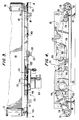
- FIG. 2 is an exploded perspective view of a vacuum feed and hold down assembly constructed in accordance with the principles of this invention;
- FIG. 3 is a fragmentary, top plan view of the transport belt of the vacuum feed and hold down assembly, such view being taken along line 3-3 in FIG. 2 and in the direction indicated;
- FIG. 4 is a side elevational view of the drive chain for the vacuum feed and hold down assembly, such view being taken along line 4-4 in FIG. 3 and in the direction indicated;
- FIG. 5 is a side elevational view of the lifting frame for the transport belt of the vacuum feed and hold down assembly, such view being taken along line 5-5 of FIG. 2 and in the direction indicated;
- FIG. 6 is a transverse, cross-sectional view of the lifting frame, such view being taken along line 6-6 of FIG. 5 and in the direction indicated;
- FIG. 7 is a fragmentary, bottom plan view of the transport belt, such view being taken along line 7-7 in FIG. 6 and in the direction indicated;
- FIG. 8 is a schematic view of the sequence of operations performed by the vacuum feed assembly; and
- FIG. 9 is a schematic representation of the pneumatic circuit employed within the vacuum feed and hold down assembly.
- Turning now to the drawings, FIG. 1 depicts, in general schematic fashion, a known, vertical configuration for a
daylight camera system 10 which may be adapted to receive, and utilize, the present invention. -
Camera system 10 includes a receptacle to receive, and retain, acassette 12 containing aroll 14 of photosensitive material.Rollers transport mechanism 20, such as a belt, advances the cut length of material onto aglass platen 22. The sheet of material, cut to length, is centered on the platen, and than is positively forced, or drawn down by suction, to press firmly against the platen. - Graphic material is arranged on
illuminated copyboard 24, and the camera, represented bylens 26, is adjusted relative to the copyboard. An exposure is then achieved, and the image is recorded on the sized sheet of photosensitive material. The exposed sheet of photosensitive material is then advanced by thetransport belt 48 into the nip defined betweenrollers compound gear 32 is operatively associated with therollers - When the operator wishes to make a plate for multiple impressions, a
removable transfer cartridge 34 is inserted into the camera system to receive the exposed lengths of photosensitive materials. The cartridge, which trips aswitch 36 when inserted into the system, uses gears 38, 40 to drive rollers (not shown) within the cartridge to take up the photosensitive material in light-tight enclosure. The cartridge is picked up byhandle 42 and removed to an alternative process for completing the platemaking process. - Under usual conditions of operation, however,
cartridge 34 will be absent, and therollers guide 44, which leads intodeveloper section 46. - FIGS. 2-7, and particularly FIG. 2, depict the details of the
vacuum feed assembly 20. In accordance with the principles of the present invention, theassembly 20 assumes the form of abelt 48 that extends between afirst roller 50 and asecond roller 52. One end of the belt fits within agroove 54 inroller 50, or is otherwise secured thereto, while the opposite end ofbelt 48 fits within a groove inroller 52, or is otherwise secured thereto. The belt is opaque, preferably black, and is longer and wider than theglass platen 22, to prevent stray light from entering the camera. The belt is a laminate of plastisol and polyester fabric, so that the belt can conform to the surface of therollers - An
elongated shaft 56 extends laterally throughroller 50. One end ofshaft 56 projects through an ear 58 onfirst side frame 60, while the opposite end ofshaft 56 projects through anear 62 on second, opposingside frame 64. Atorsion spring 66 and a collar 68 are slipped ontoshaft 56 so that an elastic coupling is formed betweenroller 50 andshaft 56. - An
elongated shaft 70 extends laterally throughroller 52. One end ofshaft 70 projects through anear 72 onfirst side frame 60, while the opposite end ofshaft 70 projects through an ear (not shown) on opposingside frame 64.Roller 52 is pinned toshaft 70. - A rigid frame surrounds the
belt 48. Such frame comprises afirst side frame 60, and asecond side frame 64; to maintain the side frames parallel, three cross-members are used to complete the frame. The first cross-member is indicated byreference numeral 74 and is situated close toroller 50, while a second, centrally located cross-member is indicated byreference numeral 76, and the third cross-member is designated 78. Cross-members 74 and 78 are similar in shape, whilecross-member 76 is considerably larger in size. - A first L-shaped
bracket 80 is secured toside frame 60 adjacent to ear 58, and asupport foot 82 extends upwardly through the bracket. A second L-shapedbracket 84 is secured toside frame 60 adjacent toear 72, and asupport foot 86 extends upwardly through the bracket. A third support foot (not shown) is secured toear 62 onside frame 64, and a fourth support foot is secured to another ear at the opposite end ofside frame 64. The support feet are adjusted vertically so that the rigid belt frame, and thetransport belt 48 associated therewith, can be maintained parallel to platen 22 (visible in FIG. 1, but not shown in FIG. 2). - A vacuum pick-up
bar 88 is secured, by suitable adhesives, to the upper surface ofbelt 48. The bar is U-shaped when viewed in vertical cross-section; a first C-shapedtrack 90 is disposed interiorly ofside frame 64.Track 90 extends longitudinally along the side frame betweencross-members side frame 60. Oneend 92 of vacuum pick-upbar 88 rests upon, and travels along,track 90. The opposite end ofvacuum bar 88 rests upon, and travels along, the companion track associated withside frame 60. The ends of the vacuum pick-up bar terminate in upstruck ears. - A
rectangular manifold 94 is secured byscrews 182, 184 (see FIG. 6) and adhesives to the upper surface ofbar 88, and fits securely within the U-shaped confines of the bar. Anair hose 96 is secured to the manifold to establish communication between a vacuum source and the interior of the manifold. - Spacer bars 98, 100 extend between
track 90 and the companion track located interiorly ofside frame 60. Afirst lift link 102 is secured to the interior ofside frame 64, and apin 104 at the lower end oflink 102 projects through an opening intrack 90. Asecond lift link 106 is also secured to the interior oftrack 90, and apin 108 at the lower end oflink 106 projects through another opening intrack 90 nearcross-member 78. A third and fourth lift link (not shown) are secured to the interior surface ofside frame 60 in a similar manner; the four lift links enable the tracks and the vacuum pick-upbar 88 extending therebetween to move a limited distance in a direction that is perpendicular to the plane ofbelt 48. - The mechanism that lifts the C-shaped tracks relative to side frames 60, 64 is shown in FIG. 2 and is identified generally by
reference character 110.Assembly 110 includes abracket 112 that is located in proximity to arectangular aperture 114 incross-member 76. Aswitch 116 is secured tobracket 112, as suggested by the dashed lead lines, and alift motor 118 is secured in proximity to the bracket. Switch 116 controls the "on" and "off" operation oflift motor 118. Acam 120 is mounted on the shaft oflift motor 118, and adrive link 122 has one end secured to anupstanding tab 124 that is secured tospacer bar 100.Lift motor 118, through the cam and its eccentric operation ofdrive link 122, is able to raise, and lower, the C-shaped tracks, which pivot about the lift links joined to side frames 60 and 64. - The mechanism that drives
rollers belt 48 secured between these rollers, is identified generally byreference number 126.Mechanism 126 is shown in FIG. 2, on a reduced scale, but is amplified and shown on an enlarged scale in FIGS. 3 and 4.Mechanism 126 is situated on the exterior ofside frame 60. -
Mechanism 126 includes areversible motor 128 that drives amain drive sprocket 130. Thesprocket 130 drives an endless linkedchain 132 that extends between asprocket 134 secured to the end ofshaft 70 and asprocket 136 secured to the end ofshaft 56.Additional sprockets - A mounting
bracket 148 is secured toside frame 60 in proximity tochain 132.Lugs motor 128, lug 150 contacts arm 154 onswitch 156 onbracket 148 and closes such switch. The switch closure causes themotor 128 to reverse direction, and throughdrive sprocket 130, the chain is driven in the opposite direction. Such motion continues untillug 152 contacts arm 158 onswitch 160 onbracket 148 and closes such switch. The driving of the chain in one direction movesbelt 48 fromroller 50 ontoroller 52, while the driving of the chain in the opposite direction reverses the direction of movement ofbelt 48. - FIG. 5 reveals additional details of the
mechanism 110 that lifts the C-shaped tracks that are connected by lift links to theside frame track 90, which has an upper and lower flange, is visible; the vacuum pick-upbar 88 travels across the width oftrack 90 while suspended between the lower flange oftrack 90 and the lower flange of the identical track secured inboard ofside frame 60. The details oflinks side frame 64 bypivot pin 162, whilelink 106 is secured toside frame 64 bypivot pin 164. Cross-members 78 and 74 are C-shaped beams when viewed in end elevation. Details of themechanism 110 that lifts thetrack 90 and the companion track inboard ofside frame 60 are also shown on a larger scale than FIG. 2. The feed out and return movement ofrollers belt 48 is paid out, and taken up, is shown by the directional arrows located adjacent to the rollers. Similarly, the vertically directed, up and down movement of the tracks, and the vacuum pick-up bar suspended therefrom, is indicated by the two-headed arrow. - FIG. 6 shows the C-shaped
track 166 that is positioned inboard ofside frame 60 and is joined thereto by a pair of lift links.Tracks track 166 are aligned with the lift links 102, 106 for C-shapedtrack 90, so that the tracks, which are joined together byspacer bars lift links 168 is shown in FIG. 6; such link is secured toside frame 60 bypivot pin 170 at its upper end, while the lower end of the link has apin 172 which projects through an opening intrack 166. - One
end 92 of vacuum pick-upbar 88 rests upontrack 90, while theopposite end 174 of thevacuum bar 88 rests upontrack 166.Manifold 94 is secured with screws and adhesive sealant to bar 88, and is seated within a channel defined on the bar. Acentral bore 176 receives one end ofair hose 96; the bore communicates with a firstvertical channel 178 and a secondvertical channel 180. - FIG. 7 shows the underside of
transport belt 48, and the outline of the manifold 94 and vacuum pick-upbar 88 secured to the upper surface of the belt. The ends 92 and 174 of the vacuum pick-upbar 88, which project beyond the belt, for engagement withtracks - Two
openings belt 48 withchannels Belt 48 is a laminate of plastisol and polyester fabric. The plastisol is removed, or omitted, in an area of the belt conforming in shape to the platen, but slightly larger in size. The polyester fabric appears as a mesh-screen 190 in FIG. 7.Mesh screen 190 extends across theopenings air hose 96 tomanifold 94 and thence throughchannels bar 88 and belt to the underside of thetransport belt 48. The suction forces cause photosensitive material to adhere to belt 48, so that the belt can advance such material through successive steps in the operation of the daylight camera employing this film transport assembly. The channels need not be cylindrical over their entire length, but may widen out at their lower ends to form a larger air inlet area. - A rectangular, rigid
main frame 192, comprisingfront channel 194,side channel 196,rear channel 198, andside channel 200 extends about thetransport belt 48 and the related assemblies for advancing and returning such belt, as well as raising and lowering same, at appropriate times in the operational cycle of the camera system. Ahinge 202 joins the main frame to the frame of the camera system, so that the main frame may be lifted upwardly to allow inspection, or repair, to the components housed therewithin. Anair cylinder 204 retains the frame in its "up" position, and also controls its gradual downward motion toward its closed position. - The sequence of operation for the above-described preferred embodiment of an automatically operated vacuum feed and hold down assembly system for a daylight camera is best understood by reference to FIGS. 8 and 9.
Rollers roll 14 retained incassette 12. The rollers are powered bygear 206, which is driven bychain 208 that passes aboutsprocket 210. Afirst motor 212 delivers power tosprocket 210. - The leading edge of photosensitive material F is advanced by
rollers roller 50 and ontoplaten 22 to a start position A. At position A, thevacuum pump 214 is turned on and suction forces are delivered overair hose 96 tomanifold 94. The forces are distributed throughbores belt 48 so that the photosensitive material is adhered thereto. Thelift mechanism 110, includinglift motor 118, is then actuated so thattracks bar 88 so that the emulsion side of the photosensitive film is spaced a small distance above the plane of the platen. Thedrive mechanism 126, includingreversible motor 128,drive sprocket 130, andchain 132, is then energized. The movement of the chain rotatesrollers transport belt 48 is then advanced a calculated distance to station B with the lift assembly remaining in the raised position. Asecond motor 216 is then turned on and such motor drives a cable 218 which movesrotary cutter 220 across the photosensitive material. Thevacuum pump 214 delivers suction forces to the manifold 94 and to the underside of thetransport belt 48 all the time so the photosensitive sheet material adheres to the belt during the transport cycles. During the cut cycle the lift assembly still remains in the raised location. Thedrive assembly 126 rotatesrollers transport belt 48. The lifting assembly is then de-energized and the cut sheet of photosensitive material is positioned at station C. The entire cut sheet is now in contact withglass platen 22. - Placement of the cut length of photosensitive material at station C insures that the photosensitive material is centered upon the platen. After centering, three-
way valve 222 terminates the suction forces flowing to transportbelt 48, and directs such forces to a vacuum hold-down channel 223 that runs about the perimeter ofplaten 22. The suction forces present inchannel 223 draw the cut length of photosensitive material F against the platen, and also pull flexible,opaque belt 48 snugly thereagainst. While the cut length of photosensitive material is pressed tightly against the platen, an exposure is made of the graphic arts materials placed upon thecopyboard 24. - After the exposure, the suction forces to channel 223 are terminated. Switching
valves belt 48 andplaten 22. Then the airflow is directed to the gripper to provide suction forces viaair hose 96. The cut sheet is then moved, in the raised position, with the belt towardrollers drive assembly 126 is activated to rotaterollers - At station D, the lifting frame remains raised but the suction force to belt 48 is terminated after the cut sheet has entered the nip of
rollers rollers developer section 46. Thedrive assembly 126 is again energized bylugs chain 132 cooperating withswitches rollers transport belt 48 is returned to its starting position, position A. - In order to insure the delivery of the suction forces produced by
vacuum pump 214 to the manifold 94, or to thechannel 223 or to be vented, at the proper time in the sequence of operations, avent valve 224 is utilized in conjunction with three-way valve 222.Valves - Whereas a preferred embodiment of the vacuum feed system has been described above, numerous changes in such system will occur to the skilled artisan. The invention, for example, may find application in known cameras, X-ray equipment, photocopiers, and the like. While the transport belt may be made of a single ply of flexible plastic or rubber, the belt is usually formed of two, or more, plies of materials glued together. Also, a pivot pin 226 (FIG. 2) may be used for further adjustment of the belt frame and the belt with respect to
glass platen 22. -
Transport belt 48, per se, is of a unique construction. The body of the belt is a polyester fabric which approximates a fine mesh screen. Plastisol is sprayed, dipped, or otherwise applied to both surfaces of the fabric except for a "window" area within the belt. This window is rectangular in shape and is slightly larger in size than the platen of the camera system. The manifold 94 is secured to the belt within the confines of the window. When suction is applied to the manifold, the mesh enhances its gripping action. When suction is applied about the platen, the mesh facilitates the drawing down of the sheet of photosensitive material centered on the platen. The belt is preferably black in color to increase its ability to prevent stray light from entering the camera system. Because of its construction, the belt exhibits excellent conformance characteristics with regard torollers
Claims (21)
- A camera system (10) including a supply (12) of photosensitive material (14), a platen (22) to receive the photosensitive material (14), a lens system (26) to expose the photosensitive material (14), and a processing station (46) for developing the exposed photosensitive material (14), in combination with a vacuum feed and hold down assembly which assembly comprises:a) a first roller (50) located at one end of the platen (22) near said supply (12) and a second roller (52) located at the opposite end of the platen (22);b) drive means (128,132) to drive said rollers;c) a flexible, opaque transport belt (48) having one end attached to said first roller (50) and having its other end attached to the second roller (52) so that said transport belt can be advanced by said drive means (128,132), said belt (48) having an upper surface, not facing the photosensitive material (14) and a lower surface facing the photosensitive material (14);d) a plurality of belt openings (186,188) formed through said transport belt (48);e) a vacuum source comprising a vacuum pump (214); andf) a conduit (96) for connecting said vacuum source with said plurality of belt openings (186,188);characterized by
a vacuum pick-up bar (88) being secured to the upper surface of said transport belt (48), being arranged to be in a raised or a lowered position, and being joined to a manifold (94) having a central bore (176) connected to a plurality of channels (178,180) which are in alignment with the belt openings (186,188) so that, when said vacuum pump (214) is actuated, a vacuum is generated through said central bore (176) and said plurality of channels (178,180) between the lower surface of said transport belt (48) and the photosensitive material (14) to draw them together, during the advancement of said transport belt (48). - A camera system (10) in combination with a vacuum feed and hold down assembly as defined in claim 1 wherein a rigid belt frame is provided to maintain the transport belt parallel to the platen, said belt frame comprising a first side frame (60) placed at one side of the platen (22) in the direction of the advancement of the transport belt (48), a second side frame (64) placed at the other side of the platen (22) in the direction of advancement of the transport belt (48) and a plurality of cross-members (74,76,78) that extend laterally across the belt, at spaced intervals, to maintain said side frames parallel to each other.
- A camera system (10) in combination with a vacuum feed and hold down assembly as defined in claim 2 wherein three cross-members (74,76,78) are utilized, two of said cross-members (74,78) being C-shaped channels.
- A camera system (10) in combination with a vacuum feed and hold down assembly as defined in claim 2 wherein a plurality of support feet (82,86) is provided for said rigid belt frame, one foot being secured to each corner of said belt frame, each foot being adjustable in height so that said belt frame can be maintained parallel to said glass platen (22).
- A camera system (10) in combination with a vacuum feed and hold down assembly as defined in claim 1 wherein a drive assembly is provided to impart rotational movement to said first and second rollers (50,52) to pay out, and take up, the transport belt (48), said first roller being mounted upon a first elongated shaft and said second roller being mounted upon a second elongated shaft said drive assembly including a motor, a sprocket (130) driven by said motor (128), a first idler secured to said first elongated shaft (56) and second idler secured to said second elongated shaft (70), an endless chain (132) trained about said sprocket and said idlers, and means for driving said chain, alternately in a first direction to pay out said transport belt and in a second direction to take up said transport belt.
- A camera system (10) in combination with a vacuum feed and hold down assembly as defined in claim 5 wherein said means for driving said chain in said first and second directions includes lugs (150,152) projecting from said chain and a pair of switches positioned in the path of movement of said lugs, one of said switches being tripped when the chain moves in one direction and the other of said switches being tripped when the chain moves in the opposite direction.
- A camera system (10) in combination with a vacuum feed and hold down assembly as defined in claim 5 wherein said motor (128) is a reversible motor, and an elastic coupling is provided between said first elongated shaft and the roller secured thereto.
- A camera system (10) in combination with a vacuum feed and hold down assembly as defined in claim 1 wherein said transport belt is black in color, is larger than the glass platen of the camera, and is executed in a material that is supple and can conform to the curvature of the first and second rollers about which it is wrapped.
- A camera system (10) in combination with a vacuum feed and hold down assembly as defined in claim 8 wherein said transport belt is formed of multiple plies of a plastic material joined together.
- A camera system (10) in combination with a vacuum feed and hold down assembly as defined in claim 1 wherein said vacuum pick-up bar (88) extends laterally across the width of said transport belt (48), one end of said bar terminating in an upstruck ear and the other end of said bar terminating in a second upstruck ear.
- A camera system (10) in combination with a vacuum feed and hold down assembly as defined in claim 10 wherein a first side frame (60) is placed at one side of the platen (22) in the direction of advancement of the transport belt (48), a second side frame (64) is placed at the other side of the platen (22) in the direction of advancement of the transport belt (48), a first C-shaped longitudinally extending track (90), is provided along one side of the platen (22) and a second C-shaped longitudinally extending track (166) is provided along the opposite side of said platen (22), one ear on said vacuum pick-up bar (88) resting on said first track and the second ear of said vacuum pick-up bar resting on said second track, whereby said vacuum pick-up bar (88) can slide freely along said tracks (90,166) as said transport belt (48) is paid out, and taken up, upon said first and second rollers (50,52).
- A camera system (10) in combination with a vacuum feed and hold down assembly as defined in claim 11 wherein lift means are provided to elevate said first and second tracks (90,166) and said vacuum pick-up bar (88) suspended therefrom.
- A camera system (10) in combination with a vacuum feed and hold down assembly as defined in claim 12 wherein spacer bars (98,100) extend between said first and second tracks (90,166) to maintain same parallel and in alignment, and said lift means are secured to one of said spacer bars (98,100).
- A camera system (10) in combination with a vacuum feed and hold down assembly as defined in claim 13 wherein said lift means includes a lift motor (118), and a drive link (122) secured between said lift motor and one of said spacer bars (98,100) to achieve upward and downward movement of said tracks.
- A camera system (10) in combination with a vacuum feed and hold down assembly as defined in claim 14 wherein said lift means further includes a cam (120) and a switch (116) actuated by said cam for controlling the operation of said lift motor (118).
- A camera system (10) in combination with a vacuum feed and hold down assembly as defined in claim 12 wherein said lift means includes a plurality of lift links (102,106) secured between said side frames and said tracks so that said tracks can be moved relative to said side frames.
- A camera system (10) in combination with a vacuum feed and hold down assembly as defined in claim 16 wherein said lift means include first and second lift links (102,106) which are secured between one of said side frames and said first track disposed inboard thereof, and third and fourth lift links which are secured between the other one of said side frames and said second track disposed inboard thereof.
- A camera system (10) in combination with a vacuum feed and hold down assembly as defined in claim 1 wherein a channel is formed around the perimeter of said platen (22), and said vacuum pump (214) is arranged to provide vacuum either to said manifold (94) or to said channel.
- A camera system (10) in combination with a vacuum feed and hold down assembly as defined in claim 18 wherein solenoid operated valves (222,224) are disposed between said vacuum pump and said manifold and said channel, said valves controlling the vacuum generated by said vacuum pump.
- A camera system (10) in combination with a vacuum feed and hold down assembly as defined in claim 1 wherein said flexible opaque transport belt is formed of a laminate of polyester fabric coated with plastisol.
- A camera system (10) in combination with a vacuum feed and hold down assembly as defined in claim 20 wherein a selected area of said belt consists only of polyester fabric so that said selected area can be drawn tightly against the platen of the camera system.
Applications Claiming Priority (2)
| Application Number | Priority Date | Filing Date | Title |
|---|---|---|---|
| US6567087A | 1987-06-25 | 1987-06-25 | |
| US65670 | 1987-06-25 |
Publications (3)
| Publication Number | Publication Date |
|---|---|
| EP0321506A1 EP0321506A1 (en) | 1989-06-28 |
| EP0321506A4 EP0321506A4 (en) | 1989-10-16 |
| EP0321506B1 true EP0321506B1 (en) | 1993-04-14 |
Family
ID=22064324
Family Applications (1)
| Application Number | Title | Priority Date | Filing Date |
|---|---|---|---|
| EP19880900913 Expired - Lifetime EP0321506B1 (en) | 1987-06-25 | 1987-12-11 | Automatically operated vacuum feed and hold down assembly for camera system |
Country Status (5)
| Country | Link |
|---|---|
| EP (1) | EP0321506B1 (en) |
| JP (1) | JPH0750303B2 (en) |
| CA (1) | CA1286138C (en) |
| DE (1) | DE3785453T2 (en) |
| WO (1) | WO1988010447A1 (en) |
Family Cites Families (1)
| Publication number | Priority date | Publication date | Assignee | Title |
|---|---|---|---|---|
| DK154739C (en) * | 1984-09-03 | 1989-05-29 | Eskofot As | REPRODUCTION CAMERA |
-
1987
- 1987-12-11 DE DE8888900913T patent/DE3785453T2/en not_active Expired - Lifetime
- 1987-12-11 JP JP63501076A patent/JPH0750303B2/en not_active Expired - Lifetime
- 1987-12-11 WO PCT/US1987/003345 patent/WO1988010447A1/en not_active Ceased
- 1987-12-11 EP EP19880900913 patent/EP0321506B1/en not_active Expired - Lifetime
- 1987-12-15 CA CA000554309A patent/CA1286138C/en not_active Expired - Fee Related
Also Published As
| Publication number | Publication date |
|---|---|
| DE3785453T2 (en) | 1993-07-29 |
| DE3785453D1 (en) | 1993-05-19 |
| JPH0750303B2 (en) | 1995-05-31 |
| CA1286138C (en) | 1991-07-16 |
| EP0321506A4 (en) | 1989-10-16 |
| WO1988010447A1 (en) | 1988-12-29 |
| EP0321506A1 (en) | 1989-06-28 |
| JPH01503738A (en) | 1989-12-14 |
Similar Documents
| Publication | Publication Date | Title |
|---|---|---|
| US3635559A (en) | Photographic printing apparatus | |
| US4772923A (en) | Automatically operated vacuum feed and hold down assembly for camera system | |
| US4389117A (en) | Microfiche separator and transport apparatus | |
| US3617127A (en) | Photographic material transport with vacuum platen | |
| GB2109569A (en) | Contact printer | |
| US4814832A (en) | Automatic vacuum feed and hold down assembly for camera system | |
| CA1286138C (en) | Automatically operated vacuum feed and hold down assembly for camerasystem | |
| JP2001228470A (en) | Method and device for sticking of polarizing plate | |
| US5381983A (en) | Apparatus for drawing out a web end from a web roll | |
| JP2773104B2 (en) | Egg container sealing device | |
| JP2851298B2 (en) | Double-sided pressure-sensitive adhesive tape, method of using the double-sided pressure-sensitive adhesive tape, and device for attaching a bonded object using the double-sided pressure-sensitive adhesive tape | |
| JPS5993B2 (en) | auto printer | |
| US4640610A (en) | Reproduction camera | |
| US4786950A (en) | Device for inserting copy and exposure material layers into a device for the continual exposure of this material | |
| US4885606A (en) | Vacuum transport and hold down belt for automatic camera | |
| JPH06347910A (en) | Film feeder for photo printing machine | |
| JPS581779Y2 (en) | Automatic printing device | |
| EP0359229A2 (en) | Vacuum contact printing apparatus for exposing an original image on a photosensitive material in contact with an original film under vacuum and a method therefor | |
| JP2811114B2 (en) | Exposure equipment | |
| JPH0521075Y2 (en) | ||
| JP2563939Y2 (en) | Color plate inspection device | |
| JP2566912Y2 (en) | Sheet transport device | |
| JPH0389354A (en) | Automatic composer | |
| JP2979016B2 (en) | Contact exposure equipment | |
| JP2539605Y2 (en) | Pin system vacuum contact printing machine |
Legal Events
| Date | Code | Title | Description |
|---|---|---|---|
| PUAI | Public reference made under article 153(3) epc to a published international application that has entered the european phase |
Free format text: ORIGINAL CODE: 0009012 |
|
| AK | Designated contracting states |
Kind code of ref document: A1 Designated state(s): DE FR GB |
|
| 17P | Request for examination filed |
Effective date: 19890627 |
|
| A4 | Supplementary search report drawn up and despatched |
Effective date: 19891016 |
|
| 17Q | First examination report despatched |
Effective date: 19911129 |
|
| GRAA | (expected) grant |
Free format text: ORIGINAL CODE: 0009210 |
|
| AK | Designated contracting states |
Kind code of ref document: B1 Designated state(s): DE FR GB |
|
| REF | Corresponds to: |
Ref document number: 3785453 Country of ref document: DE Date of ref document: 19930519 |
|
| ET | Fr: translation filed | ||
| PLBE | No opposition filed within time limit |
Free format text: ORIGINAL CODE: 0009261 |
|
| STAA | Information on the status of an ep patent application or granted ep patent |
Free format text: STATUS: NO OPPOSITION FILED WITHIN TIME LIMIT |
|
| 26N | No opposition filed | ||
| PGFP | Annual fee paid to national office [announced via postgrant information from national office to epo] |
Ref country code: GB Payment date: 19941005 Year of fee payment: 8 |
|
| PGFP | Annual fee paid to national office [announced via postgrant information from national office to epo] |
Ref country code: FR Payment date: 19941108 Year of fee payment: 8 |
|
| PGFP | Annual fee paid to national office [announced via postgrant information from national office to epo] |
Ref country code: DE Payment date: 19941122 Year of fee payment: 8 |
|
| REG | Reference to a national code |
Ref country code: FR Ref legal event code: TP |
|
| REG | Reference to a national code |
Ref country code: GB Ref legal event code: 732E |
|
| PG25 | Lapsed in a contracting state [announced via postgrant information from national office to epo] |
Ref country code: GB Effective date: 19951211 |
|
| GBPC | Gb: european patent ceased through non-payment of renewal fee |
Effective date: 19951211 |
|
| PG25 | Lapsed in a contracting state [announced via postgrant information from national office to epo] |
Ref country code: FR Effective date: 19960830 |
|
| PG25 | Lapsed in a contracting state [announced via postgrant information from national office to epo] |
Ref country code: DE Effective date: 19960903 |
|
| REG | Reference to a national code |
Ref country code: FR Ref legal event code: ST |