EP0320911B1 - A method and device for rotating prisms in a panel for multiple messages - Google Patents
A method and device for rotating prisms in a panel for multiple messages Download PDFInfo
- Publication number
- EP0320911B1 EP0320911B1 EP88120910A EP88120910A EP0320911B1 EP 0320911 B1 EP0320911 B1 EP 0320911B1 EP 88120910 A EP88120910 A EP 88120910A EP 88120910 A EP88120910 A EP 88120910A EP 0320911 B1 EP0320911 B1 EP 0320911B1
- Authority
- EP
- European Patent Office
- Prior art keywords
- prisms
- panel
- movement
- rotation
- rotating
- Prior art date
- Legal status (The legal status is an assumption and is not a legal conclusion. Google has not performed a legal analysis and makes no representation as to the accuracy of the status listed.)
- Expired - Lifetime
Links
- 238000000034 method Methods 0.000 title claims description 16
- 230000033001 locomotion Effects 0.000 claims description 30
- 230000005540 biological transmission Effects 0.000 claims description 7
- 238000000926 separation method Methods 0.000 claims description 4
- 230000011664 signaling Effects 0.000 claims description 4
- 125000004122 cyclic group Chemical group 0.000 claims description 3
- 241000735235 Ligustrum vulgare Species 0.000 abstract 1
- 239000000428 dust Substances 0.000 description 1
- 230000000694 effects Effects 0.000 description 1
- 230000001681 protective effect Effects 0.000 description 1
- 230000003252 repetitive effect Effects 0.000 description 1
- 239000004576 sand Substances 0.000 description 1
- 239000011800 void material Substances 0.000 description 1
Images

Classifications
-
- G—PHYSICS
- G09—EDUCATION; CRYPTOGRAPHY; DISPLAY; ADVERTISING; SEALS
- G09F—DISPLAYING; ADVERTISING; SIGNS; LABELS OR NAME-PLATES; SEALS
- G09F11/00—Indicating arrangements for variable information in which the complete information is permanently attached to a movable support which brings it to the display position
- G09F11/02—Indicating arrangements for variable information in which the complete information is permanently attached to a movable support which brings it to the display position the display elements being secured to rotating members, e.g. drums, spindles
- G09F11/025—Indicating arrangements for variable information in which the complete information is permanently attached to a movable support which brings it to the display position the display elements being secured to rotating members, e.g. drums, spindles the members being rotated simultaneously, each face of the member carrying a part of the sign
Definitions
- prism panels that is, panels comprising rotating prism elements, generally of triangular or square section (see for example FR-A-2602898 and CH-A-662897).
- prisms are provided side by side, whose faces are positioned towards the external part of the panel, adjacent and flanked to each other, to form the representative surface of the panel.
- flanked prisms having a triangular section does not show any difficulty, some problems occur when such prism section is square or has more than four sides. In fact, in this case, two adjacent prisms must be spaced at least of a minimum value, below which value the rotation is made physically impossible by the prism geometry.
- the two flanked sides 3a and 4a of those prisms must be spaced from each other at least of a " ⁇ " value equal to the difference between the diagonal of the prism section and one of its sides.
- the empty spaces that are thus formed between two prisms negatively affect the quality of the displayed message.
- the representative efficiency of a panel is defined as the ratio between the area effectively used for the message and the available area, it is found that in the above disclosed case the representative efficiency is lower than 70 %, which is an excessively low value.
- the object of this invention is to provide a method and a device which solve the above mentioned problems, allowing the rotation of prisms with four sides or more in a multiple message panel having a high representative efficiency, that is in a panel where such prisms are positioned substantially in close contact one with each other.
- this invention relates to a method for rotating the prisms composing the representative surface of a multiple message panel, characterised in that it comprises the following steps: moving a group of non-adjacent alternately positioned prisms away from said panel rapresentative surface; rotating at least a part of the prisms during or after said movement; and re-approaching the moved prisms, aligning them with the others, during or after said rotation, to recompose said representative surface with a new message.
- the invention further concerns a new device for rotating of prisms with four or more sides and forming the representative surface of a multiple message signalling panel, characterised in that it comprises: means to move a group of non-adjacent alternately positioned prisms away from said panel representative surface; means to rotate at least a part of the prisms during or after said movement; and means to re-approach the moved prisms, aligning them with the others, during of after said rotation, to recompose the representative surface.
- the present invention concerns a multiple message signalling panel of the type described and provided with a representative surface composed of prisms with four or more sides, characterised in that it uses a prism rotation method and device of the type described above.
- a number of square section prisms define a panel representative surface for showing multiple message signals, said prisms being placed adjacent to each other and aligned in such a way that all the faces towards the panel outer part lie on the same plane forming said panel representative surface.
- the distance between two opposite faces, 3a and 4a, of two adjacent prisms must be at least equal to the difference between the diagonal and the side of the prism square section; if the prisms are rotated in alternate groups, that is in the case where the prisms located in even positions are rotated first and then the prisms located in odd positions are rotated (or viceversa), the distance as necessary for allowing the prism rotation is halved with respect to the previous one.
- the present invention allows to use panels formed by adjacent prisms of four or more sides, keeping the distance between them to a minimum as necessary for a translation movement of each prism with reference to the adjacent ones, as illustrated in Fig. 2.
- the method according to this invention foresees the use of narrowly adjacent prisms and the movement of a part of them in a direction perpendicular to the plane of the representative surface before the rotation of all the prisms.
- the panel of fig. 3 comprises prisms 1 and 3, which will be moved away, having a section of sizes lower than those of the corresponding section of prisms 2 and 4, that are rotated only: this allows the prisms 1 and 3 to be translated for a distance lower than that necessary in the panel of figure 2.
- the prisms 1 and 3 that should be moved away and re-uzed, are connected to a frame 5 in order to obtain an identical and simultaneous movement; as it can be noticed, the faces of all the prisms are flanked strictly next to each other, contributing to form a first message, that has been sketched by indicating such faces with the letter A.
- the prism group 1 and 3 is moved away (figure 4) by a predetermined distance and then a preferably simultaneous rotation of the two prisms groups 1, 3 and 2, 4 is carried-out (figure 5).
- such rotation has an amplitude of 90 degrees, so that at the end thereof all the prisms faces turned towards the outer part of the panel, i.e. those turned towards the right part of the drawing, are marked with B.
- the prisms 1 and 3 are re-approached and aligned to the prisms 2 and 4 (figure 6) to form a second message, different from the one previously shown.
- the method indicated above can be performed essentially with two different procedures; the first procedure foresees to carry out in time sequence, the three steps of: moving away the prisms, rotating the prisms and re-approaching the moved prisms, while the second procedure foresees that such operations are performed simultaneously.
- the device for controlling the prism rotation must comprise, besides the necessary means to move and rotate the prisms on the panel, also sensors or analogous means of detect the position of the mobile prisms in a longitudinal direction, to regulate in sequence the operation of the prism moving away, rotating and re-approaching means.
- the operations of moving away, re-approaching and rotating the prisms are performed with continuous movements, with a cyclic separation-approaching speed and with a variable rotation speed.
- the rotation speed which is in general the same for all the prisms, will be minimum when the prisms 1 and 3 are still positioned between the prisms 2 and 4 (that is at the beginning of the prism separation movement and at the end of the re-approaching movement), and that said rotation speed will gradually increase when such prisms 1 and 3 are moved away from the, panel surface.
- Said rotational speed will be then maximum when the two prism groups are at the maximum distance therebetween, i.e. at the end of the separation movement and at the start of the re-approaching movement.
- a device to perform the above described movements is preferably of the type with a fully mechanical operation, and one possible embodiment thereof is schematically shown in figure 7.
- the device shown in figure 7 comprises a motor 11 that activates a driving shaft 12 with two outputs; the first output controls the spreading away-approaching movement at a given speed and comprises a crank gear 15 fixed to the already described frame 5 coupled to prisms 1 and 3 that are mobile in a direction perpendicular to the panel plane.
- the second output controls the described continuous rotation movement at a multiple speed; such output consists of a transmission system with elliptical gears, as shown by two wheels 16 and 17 having an elliptical shape.
- the elliptical gear 16 is attached to the driving shaft 12 and therefore it has a constant rotational speed, while the second wheel 17 is attached to a transmission shaft 18 and its rotational speed varies in a way typical of the elliptical gear systems, that is from a minimum value to a maximum value and then again to a minimum value, in relation to the angular position between the gears 16 and 17.
- any other type of gear system can be used providing that it gives a similar type of speed graph.
- the rotating motion of shaft 18 is transmitted to others shafts 19 and 21 through an angular gear transmission system 20, that may be formed, for example, by cone shaped gears (not shown).
- the shaft 19 can move longitudinally through the transmission system 20.
- the shaft 21 is instead "fixed", in that it can only rotate around its own longitudinal axis to control the rotation of prisms 2 and 4 by means of conical gear pairs 24 and 25.
- the shaft 19 controls the rotation of another shaft 22, parallel to shaft 21, through a transmission system or conical gear pair 23; this shaft 22 in turn controls the rotation of prisms 1 and 3 by means of conical gear pairs 26 and 27, in a manner similar to that of prisms 2 and 4.
- said frame 5 comprises shafts 19 and 22 and preferably also an extra stiffening element 28, which does not rotate but runs longitudinally through a support 29.
- Figure 9 and 10 show in cross-section two further possible embodiments of the invention, where at least a part of the prisms has a pentagonal section.
- both the prisms of greater sizes 7, 7' i.e. the prisms exposed to the rotation movement only
- the prisms of lower sizes 9 are of pentagonal section.
- the side faces of prisms 7 and 7' are concave, to be able to house between them the prisms of lower section 9.
- the operation is the same of the four sides already described type.
- a square section prism 8 is positioned between two pentagonal prisms 6 and 6' with concave faces.
- one of the faces of prism 8 is used for two different functions: to execute a message and to contribute to form a void message, that is the prisms show no understandable message.
- the face 10' of prism 8 corresponds to the faces 10 and 14 of prism 6 (and to the equivalent face of prism 6').
- the exact reciprocal positioning of faces 10' and 14 is obtained by rotating for four positions in the same direction the prisms 6, 6' and 8; by reversely rotating these prisms for an equal number of positions the original position is again obtained, with alignment of faces 10 and 10'.
Landscapes
- Physics & Mathematics (AREA)
- General Physics & Mathematics (AREA)
- Engineering & Computer Science (AREA)
- Theoretical Computer Science (AREA)
- Projection Apparatus (AREA)
- Optical Elements Other Than Lenses (AREA)
- Illuminated Signs And Luminous Advertising (AREA)
- Displays For Variable Information Using Movable Means (AREA)
Abstract
Description
- Multiple message panels are well known and used in many activity areas, whenever it is necessary to display repetitive information, generally in the form of images integrated with alphanumeric messages. Besides the inexpensiveness of their operation, the essential requirements of these type of panels are to a great extent determined by the environment where these panels will be operable; as in general this environment is outdoors, the panels must be able to operate in the most variable conditions, even in extreme conditions, such as in a temperature range from - 20 degrees to +50 degrees centigrade, in the presence of strong winds (i.e. with gusts of wind generating thrusts up to 150 kg/m²) or in the presence of sand and dust. In addition, said panels must be easily visible, remotedly operable, easily maintenable, and they should not need a protective window for the message surface.
- Among the various types of available panels, those which better satisfy the above indicated requirements are the so-called "prism" panels, that is, panels comprising rotating prism elements, generally of triangular or square section (see for example FR-A-2602898 and CH-A-662897). Many prisms are provided side by side, whose faces are positioned towards the external part of the panel, adjacent and flanked to each other, to form the representative surface of the panel.
- In order to change the message displayed by such representative surface, same or all of the prisms are rotated until a new selected message is obtained; however this rotation is the source of the main inconvenience shown by these panels.
- Actually, while the rotation of flanked prisms having a triangular section does not show any difficulty, some problems occur when such prism section is square or has more than four sides. In fact, in this case, two adjacent prisms must be spaced at least of a minimum value, below which value the rotation is made physically impossible by the prism geometry.
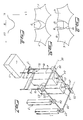
- As better shown in figure 1, in order to perform a simultaneous rotation of two square section adjacent prisms, the two flanked
sides 3a and 4a of those prisms must be spaced from each other at least of a "λ" value equal to the difference between the diagonal of the prism section and one of its sides. - Actually, if "l" is the length value of one side of the prism square section, the following relationship should be valid:

- Obviously the empty spaces that are thus formed between two prisms negatively affect the quality of the displayed message. If the representative efficiency of a panel is defined as the ratio between the area effectively used for the message and the available area, it is found that in the above disclosed case the representative efficiency is lower than 70 %, which is an excessively low value.
- As an alternative, it has been thought to successively rotate the prisms in two groups each formed by non-adjacent prisms: that is to rotate alternate prisms, first rotating the prisms located in the even positions and then rotating the ones in the odd positions (or viceversa).
- However, even if in this way the distance required to allow the rotation, is halved, the panel representative efficiency is still lower than 78 %. Moreover, the control of this type of rotation is uselessly too complex and elaborate for the modest gain in the representative efficiency.
- Therefore, there is the need for a method and a device to rotate prisms with four or more sides in a multiple message panel that allow to perform such rotation even in panels with high representative efficiency.
- The object of this invention is to provide a method and a device which solve the above mentioned problems, allowing the rotation of prisms with four sides or more in a multiple message panel having a high representative efficiency, that is in a panel where such prisms are positioned substantially in close contact one with each other.
- More particularly, this invention relates to a method for rotating the prisms composing the representative surface of a multiple message panel, characterised in that it comprises the following steps: moving a group of non-adjacent alternately positioned prisms away from said panel rapresentative surface; rotating at least a part of the prisms during or after said movement; and re-approaching the moved prisms, aligning them with the others, during or after said rotation, to recompose said representative surface with a new message.
- The invention further concerns a new device for rotating of prisms with four or more sides and forming the representative surface of a multiple message signalling panel, characterised in that it comprises: means to move a group of non-adjacent alternately positioned prisms away from said panel representative surface; means to rotate at least a part of the prisms during or after said movement; and means to re-approach the moved prisms, aligning them with the others, during of after said rotation, to recompose the representative surface.
- Moreover, the present invention concerns a multiple message signalling panel of the type described and provided with a representative surface composed of prisms with four or more sides, characterised in that it uses a prism rotation method and device of the type described above.
- The invention will be now described more in detail with reference to the attached drawings, wherein:
- Figure 1 is a schematic perspective view of a prism panel according to the state of the art;
- Figure 2 is a schematic perspective view of a panel embodiment according to the invention;
- Figures 3, 4, 5 and 6 illustrate the phases of prism rotation in a modified embodiment;
- Fig 7 is a perspective schematic view of a device according to the invention;
- Figure 8 shows a graph of the transmission ratio in a part of the device of Figure 7;
- Figure 9 is a partial section view of a further embodiment of the invention; and
- Figure 10 is a partial view of an embodiment analogous to that shown in Fig 9, with pentagonal section prisms.
- As previously indicated, in the embodiment according to the state of the art as schematically shown in Figure 1, a number of square section prisms define a panel representative surface for showing multiple message signals, said prisms being placed adjacent to each other and aligned in such a way that all the faces towards the panel outer part lie on the same plane forming said panel representative surface.
- To be able to rotate the prisms in order to change the shown message on the representative surface, it is necessary that such prisms are spaced apart for a value sufficient to allow an alternate or simultaneous rotation. In the first case, the distance between two opposite faces, 3a and 4a, of two adjacent prisms must be at least equal to the difference between the diagonal and the side of the prism square section; if the prisms are rotated in alternate groups, that is in the case where the prisms located in even positions are rotated first and then the prisms located in odd positions are rotated (or viceversa), the distance as necessary for allowing the prism rotation is halved with respect to the previous one. The present invention allows to use panels formed by adjacent prisms of four or more sides, keeping the distance between them to a minimum as necessary for a translation movement of each prism with reference to the adjacent ones, as illustrated in Fig. 2.
- In fact, the method according to this invention foresees the use of narrowly adjacent prisms and the movement of a part of them in a direction perpendicular to the plane of the representative surface before the rotation of all the prisms.
- As better shown in Figure 2 with the dashed lines 1' and 3', one of two groups, each formed by non-adjacent prisms, is moved away, that is the group formed by prisms 1 and 3, while the
prisms - The steps of the method according to this invention are shown in figures 3 to 6, where a preferred embodiment, in alternative to that of figure 2, is shown.
- Actually, the panel of fig. 3 comprises prisms 1 and 3, which will be moved away, having a section of sizes lower than those of the corresponding section of
prisms - In the preferred embodiment of figure 3, the prisms 1 and 3, that should be moved away and re-approched, are connected to a
frame 5 in order to obtain an identical and simultaneous movement; as it can be noticed, the faces of all the prisms are flanked strictly next to each other, contributing to form a first message, that has been sketched by indicating such faces with the letter A. - When it is necessary to change the shown message, the prism group 1 and 3 is moved away (figure 4) by a predetermined distance and then a preferably simultaneous rotation of the two
prisms groups - In the example shown in figures 3 to 6, such rotation has an amplitude of 90 degrees, so that at the end thereof all the prisms faces turned towards the outer part of the panel, i.e. those turned towards the right part of the drawing, are marked with B. At this point the prisms 1 and 3 are re-approached and aligned to the
prisms 2 and 4 (figure 6) to form a second message, different from the one previously shown. - The method indicated above can be performed essentially with two different procedures; the first procedure foresees to carry out in time sequence, the three steps of: moving away the prisms, rotating the prisms and re-approaching the moved prisms, while the second procedure foresees that such operations are performed simultaneously.
- In the first case, the device for controlling the prism rotation must comprise, besides the necessary means to move and rotate the prisms on the panel, also sensors or analogous means of detect the position of the mobile prisms in a longitudinal direction, to regulate in sequence the operation of the prism moving away, rotating and re-approaching means.
- However, since this solution involves the necessity of interlocked movements as controlled by sensors, it is difficult to warrant a sufficient reliability in the previously mentioned different conditions of panel use. This in why the second solution is preferred.
- As already indicated, in this second case the operations of moving away, re-approaching and rotating the prisms are performed with continuous movements, with a cyclic separation-approaching speed and with a variable rotation speed. In particular, it will be necessary that the rotation speed, which is in general the same for all the prisms, will be minimum when the prisms 1 and 3 are still positioned between the
prisms 2 and 4 (that is at the beginning of the prism separation movement and at the end of the re-approaching movement), and that said rotation speed will gradually increase when such prisms 1 and 3 are moved away from the, panel surface. - Said rotational speed will be then maximum when the two prism groups are at the maximum distance therebetween, i.e. at the end of the separation movement and at the start of the re-approaching movement.
- A device to perform the above described movements is preferably of the type with a fully mechanical operation, and one possible embodiment thereof is schematically shown in figure 7. The device shown in figure 7 comprises a
motor 11 that activates a driving shaft 12 with two outputs; the first output controls the spreading away-approaching movement at a given speed and comprises acrank gear 15 fixed to the already describedframe 5 coupled to prisms 1 and 3 that are mobile in a direction perpendicular to the panel plane. - The second output controls the described continuous rotation movement at a multiple speed; such output consists of a transmission system with elliptical gears, as shown by two
wheels 16 and 17 having an elliptical shape. The elliptical gear 16 is attached to the driving shaft 12 and therefore it has a constant rotational speed, while thesecond wheel 17 is attached to atransmission shaft 18 and its rotational speed varies in a way typical of the elliptical gear systems, that is from a minimum value to a maximum value and then again to a minimum value, in relation to the angular position between thegears 16 and 17. - This speed variation is better represented in the graph of figure 8, where the rotation angle of the driving shaft 12 (and therefore of wheel 16) is reported on the abscissa axis, while on the ordinate axis is reported the τ value, which is the ratio between the angular velocity of
wheel 17 and that of wheel 16 (therefore that of the driving shaft 12). - Of course, any other type of gear system can be used providing that it gives a similar type of speed graph. Now, coming back to the device of figure 7, the rotating motion of
shaft 18 is transmitted toothers shafts gear transmission system 20, that may be formed, for example, by cone shaped gears (not shown). As shown by the dashed line 19', theshaft 19 can move longitudinally through thetransmission system 20. Theshaft 21 is instead "fixed", in that it can only rotate around its own longitudinal axis to control the rotation ofprisms conical gear pairs shaft 19 controls the rotation of anothershaft 22, parallel toshaft 21, through a transmission system orconical gear pair 23; thisshaft 22 in turn controls the rotation of prisms 1 and 3 by means ofconical gear pairs 26 and 27, in a manner similar to that ofprisms - Then all prisms rotate with the same angular speed, which is the one of
shaft 18. - On the basis of what has been illustrated, said
frame 5 comprisesshafts stiffening element 28, which does not rotate but runs longitudinally through asupport 29. - Figure 9 and 10 show in cross-section two further possible embodiments of the invention, where at least a part of the prisms has a pentagonal section. In figure 10 both the prisms of greater sizes 7, 7' (i.e. the prisms exposed to the rotation movement only) and the prisms of
lower sizes 9, are of pentagonal section. In this way it is possible to obtain the display of at least five different messages; as it can be noticed, the side faces of prisms 7 and 7' are concave, to be able to house between them the prisms oflower section 9. In this case, the operation is the same of the four sides already described type. - In figure 9, between two pentagonal prisms 6 and 6' with concave faces, a
square section prism 8 is positioned. In this case one of the faces ofprism 8 is used for two different functions: to execute a message and to contribute to form a void message, that is the prisms show no understandable message. For example, the face 10' ofprism 8 corresponds to thefaces faces 10' and 14 is obtained by rotating for four positions in the same direction theprisms 6, 6' and 8; by reversely rotating these prisms for an equal number of positions the original position is again obtained, with alignment offaces 10 and 10'.
Claims (14)
- A method for rotating the prisms with four or more faces composing the representative surface of a multiple message panel, characterized in that it comprises the following steps: moving a group of non-adjacent alternately positioned prisms away from said panel rapresentative surface; rotating at least a part of the prisms during or after said movement; and re-approaching the moved prisms, aligning them with the others, during or after said rotation, to recompose said representative surface with a new message.
- A method according to claim 1, characterized in that the steps of spreading apart, rotating and re-approaching the prisms are carried-out in a time sequence; and in that one or more sensors detect the positions of said prisms in order to control the passage from one step to the next one.
- A method according to claim 1, characterized in that said moving and rotating steps are carried-out simultaneously, with a continuous movement and with a speed variable rotation speed to avoid interference between the prisms in motion.
- A method according to claim 3, characterized in that said rotation speed has a minimum value in correspondence to the beginning of the prism away movement and to the end of the re-approaching movement, and in that said rotation speed has a maximum value at the end of the prism separation movement and the start of the re-approaching movement.
- A device for rotating prisms with four or more sides and forming the representative surface of a multiple message signalling panel, characterized in that it comprises: means to move a group of non-adjacent alternately positioned prisms away from said panel representative surface; means to rotate at least a part of the prisms during or after said movement; and means to re-approach the moved prisms, aligning them with the others, during or after said rotation, to recompose the representative surface.
- A device according to claim 5, characterized in that said means for separating and approaching the prisms include a frame holding the prisms designed to be moved, said frame being movable in a direction perpendicular to the panel plane.
- A device according to claim 5, characterized in that it includes one or more sensors for detecting the positions of said prisms, in order to control in sequence the operation of said prism separating, re-approaching and rotating means.
- A device according to claim 5, characterized in that said separating, re-approaching and rotating means operate in a simultaneous manner, with a continuous movement and with a separation-reapproching speed which is cyclic and a variable rotation speed, to avoid interferences between the prisms in motion.
- A device according to claim 8, characterized in that such means include a driving shaft having two outputs and at least an elliptical gear transmission system.
- A device according to claim 9, characterized in that one of said driving shaft outputs controls a continuous prism separation and re-approaching movement with a cyclic speed and the other shaft output controls a continuous rotation movement at a variable speed, such controls operating by means of said elliptical gear system.
- A multiple messages signalling panel, of the type having a representative surface defined by prisms having fours or more sides, characterized in that it comprises a prism rotating device according to one of claims 5 to 10, and in that said rotation is carried-out following a method according to one of claims 1 to 4.
- A panel according to claim 11, characterized in that those prisms carrying-out said separation-reapproaching movement present a cross-section having sizes lower than the cross-section of prisms carrying-out a rotation movement only.
- A panel according to claim 12, characterized in that said prisms having a greater section are prisms with pentagonal sections, and said prisms with a lower section are prisms with square sections.
- A panel according to claim 12, characterized in that all the prisms have a pentagonal section and in that the prisms with greater sections have concave faces.
Priority Applications (1)
| Application Number | Priority Date | Filing Date | Title |
|---|---|---|---|
| AT88120910T ATE86774T1 (en) | 1987-12-16 | 1988-12-14 | METHOD AND DEVICE FOR ROTATION OF THE PRISMS IN A PANEL FOR MULTIPLE INDICATIONS. |
Applications Claiming Priority (2)
| Application Number | Priority Date | Filing Date | Title |
|---|---|---|---|
| IT2303087 | 1987-12-16 | ||
| IT23030/87A IT1223492B (en) | 1987-12-16 | 1987-12-16 | PROCEDURE AND DEVICE FOR THE ROTATION OF PRISMS IN A MULTIPLE MESSAGE PANEL |
Publications (2)
| Publication Number | Publication Date |
|---|---|
| EP0320911A1 EP0320911A1 (en) | 1989-06-21 |
| EP0320911B1 true EP0320911B1 (en) | 1993-03-10 |
Family
ID=11203070
Family Applications (1)
| Application Number | Title | Priority Date | Filing Date |
|---|---|---|---|
| EP88120910A Expired - Lifetime EP0320911B1 (en) | 1987-12-16 | 1988-12-14 | A method and device for rotating prisms in a panel for multiple messages |
Country Status (5)
| Country | Link |
|---|---|
| EP (1) | EP0320911B1 (en) |
| AT (1) | ATE86774T1 (en) |
| DE (1) | DE3879128T2 (en) |
| ES (1) | ES2041295T3 (en) |
| IT (1) | IT1223492B (en) |
Families Citing this family (5)
| Publication number | Priority date | Publication date | Assignee | Title |
|---|---|---|---|---|
| FR2703177B1 (en) * | 1993-03-26 | 1995-07-13 | Putteman Claude | DYNAMIC MULTIPLE DISPLAY DEVICE WITH ROTATING SQUARE PRISMS. |
| AU706975B2 (en) * | 1995-04-18 | 1999-07-01 | Precise Craft Pty Ltd. | Improvements to gaming machines |
| PL351103A1 (en) * | 2001-12-10 | 2003-06-16 | Marek Kabat | Varying image information and advertisement display board |
| US7509762B2 (en) * | 2005-05-10 | 2009-03-31 | Ayorinde Ajumobi | Multi-sided display sign apparatus |
| RU2344487C1 (en) * | 2007-04-09 | 2009-01-20 | Игорь Викторович Жилин | Advertisement device to produce dynamic information |
Family Cites Families (3)
| Publication number | Priority date | Publication date | Assignee | Title |
|---|---|---|---|---|
| US2360780A (en) * | 1942-06-01 | 1944-10-17 | Madison P Mccarty | Changeable display device |
| CH662897A5 (en) * | 1984-04-19 | 1987-10-30 | Markus Rohner | Advertising panel |
| FR2602898A1 (en) * | 1986-08-05 | 1988-02-19 | Amsellem Maurice | Improvement to moving advertising panels |
-
1987
- 1987-12-16 IT IT23030/87A patent/IT1223492B/en active
-
1988
- 1988-12-14 ES ES198888120910T patent/ES2041295T3/en not_active Expired - Lifetime
- 1988-12-14 EP EP88120910A patent/EP0320911B1/en not_active Expired - Lifetime
- 1988-12-14 DE DE8888120910T patent/DE3879128T2/en not_active Expired - Fee Related
- 1988-12-14 AT AT88120910T patent/ATE86774T1/en active
Also Published As
| Publication number | Publication date |
|---|---|
| ES2041295T3 (en) | 1993-11-16 |
| DE3879128D1 (en) | 1993-04-15 |
| IT1223492B (en) | 1990-09-19 |
| IT8723030A0 (en) | 1987-12-16 |
| ATE86774T1 (en) | 1993-03-15 |
| EP0320911A1 (en) | 1989-06-21 |
| DE3879128T2 (en) | 1993-06-17 |
Similar Documents
| Publication | Publication Date | Title |
|---|---|---|
| DE69318489T2 (en) | Vehicle navigation system | |
| DE60203769T3 (en) | Examination device for the examination of transparent liquid-filled containers | |
| US4158270A (en) | Device for driving sliding windows | |
| EP0320911A1 (en) | A method and device for rotating prisms in a panel for multiple messages | |
| CA2112604A1 (en) | Liquid Jetting Apparatus | |
| EP0886068A3 (en) | Gear pump with multiple driven shafts | |
| EP0135772B1 (en) | Operation control apparatus for robots | |
| EP1729275B1 (en) | Multi-sided display sign apparatus | |
| US3992961A (en) | Numerically controlled reversible gear system for removing backlash | |
| DE58906787D1 (en) | Backlash-free multi-pinion drive. | |
| DE19963990C2 (en) | Warp knitting machine with pattern device | |
| US4444076A (en) | Rocking type flying shears with stationary shearing function | |
| US4236409A (en) | Device for indicating optimum sail position | |
| CN212047180U (en) | Stepless speed change automatic telescopic road condition capturing system | |
| EP0000290B1 (en) | Rolling machine | |
| DE10039687A1 (en) | Vehicle-mounted navigation system displays fixed length base arrow along with variable length arrow whose length reduces as the vehicle approaches desired direction | |
| US4202230A (en) | Rotary cutter | |
| EP0420682A2 (en) | Meshing gear members | |
| GB2257811A (en) | Display system. | |
| CA2304892A1 (en) | Wing movement for ornithopters and apparatus of the like | |
| JPS6018653A (en) | Driving device | |
| DE3363294D1 (en) | Device for successive display of different images | |
| CN211787974U (en) | Splicing structure of rotary display screen | |
| DE19757957C2 (en) | Motorized leveling device | |
| EP0319654B1 (en) | Method and device to scan an area |
Legal Events
| Date | Code | Title | Description |
|---|---|---|---|
| PUAI | Public reference made under article 153(3) epc to a published international application that has entered the european phase |
Free format text: ORIGINAL CODE: 0009012 |
|
| AK | Designated contracting states |
Kind code of ref document: A1 Designated state(s): AT BE CH DE ES FR GB GR LI LU NL SE |
|
| 17P | Request for examination filed |
Effective date: 19891124 |
|
| 17Q | First examination report despatched |
Effective date: 19920415 |
|
| GRAA | (expected) grant |
Free format text: ORIGINAL CODE: 0009210 |
|
| AK | Designated contracting states |
Kind code of ref document: B1 Designated state(s): AT BE CH DE ES FR GB GR LI LU NL SE |
|
| PG25 | Lapsed in a contracting state [announced via postgrant information from national office to epo] |
Ref country code: NL Effective date: 19930310 Ref country code: GR Free format text: LAPSE BECAUSE OF FAILURE TO SUBMIT A TRANSLATION OF THE DESCRIPTION OR TO PAY THE FEE WITHIN THE PRESCRIBED TIME-LIMIT Effective date: 19930310 Ref country code: BE Effective date: 19930310 Ref country code: AT Effective date: 19930310 |
|
| REF | Corresponds to: |
Ref document number: 86774 Country of ref document: AT Date of ref document: 19930315 Kind code of ref document: T |
|
| REF | Corresponds to: |
Ref document number: 3879128 Country of ref document: DE Date of ref document: 19930415 |
|
| ET | Fr: translation filed | ||
| NLV1 | Nl: lapsed or annulled due to failure to fulfill the requirements of art. 29p and 29m of the patents act | ||
| REG | Reference to a national code |
Ref country code: ES Ref legal event code: FG2A Ref document number: 2041295 Country of ref document: ES Kind code of ref document: T3 |
|
| PGFP | Annual fee paid to national office [announced via postgrant information from national office to epo] |
Ref country code: GB Payment date: 19931213 Year of fee payment: 6 |
|
| PGFP | Annual fee paid to national office [announced via postgrant information from national office to epo] |
Ref country code: CH Payment date: 19931214 Year of fee payment: 6 |
|
| PGFP | Annual fee paid to national office [announced via postgrant information from national office to epo] |
Ref country code: ES Payment date: 19931217 Year of fee payment: 6 |
|
| PGFP | Annual fee paid to national office [announced via postgrant information from national office to epo] |
Ref country code: DE Payment date: 19931223 Year of fee payment: 6 |
|
| PG25 | Lapsed in a contracting state [announced via postgrant information from national office to epo] |
Ref country code: LU Free format text: LAPSE BECAUSE OF NON-PAYMENT OF DUE FEES Effective date: 19931231 |
|
| PLBE | No opposition filed within time limit |
Free format text: ORIGINAL CODE: 0009261 |
|
| STAA | Information on the status of an ep patent application or granted ep patent |
Free format text: STATUS: NO OPPOSITION FILED WITHIN TIME LIMIT |
|
| 26N | No opposition filed | ||
| PGFP | Annual fee paid to national office [announced via postgrant information from national office to epo] |
Ref country code: SE Payment date: 19941207 Year of fee payment: 7 |
|
| PG25 | Lapsed in a contracting state [announced via postgrant information from national office to epo] |
Ref country code: GB Effective date: 19941214 |
|
| PGFP | Annual fee paid to national office [announced via postgrant information from national office to epo] |
Ref country code: FR Payment date: 19941223 Year of fee payment: 7 |
|
| PG25 | Lapsed in a contracting state [announced via postgrant information from national office to epo] |
Ref country code: LI Effective date: 19941231 Ref country code: CH Effective date: 19941231 |
|
| EAL | Se: european patent in force in sweden |
Ref document number: 88120910.0 |
|
| GBPC | Gb: european patent ceased through non-payment of renewal fee |
Effective date: 19941214 |
|
| REG | Reference to a national code |
Ref country code: CH Ref legal event code: PL |
|
| PG25 | Lapsed in a contracting state [announced via postgrant information from national office to epo] |
Ref country code: DE Effective date: 19950901 |
|
| PG25 | Lapsed in a contracting state [announced via postgrant information from national office to epo] |
Ref country code: SE Effective date: 19951215 Ref country code: ES Free format text: LAPSE BECAUSE OF NON-PAYMENT OF DUE FEES Effective date: 19951215 |
|
| PG25 | Lapsed in a contracting state [announced via postgrant information from national office to epo] |
Ref country code: FR Effective date: 19960830 |
|
| REG | Reference to a national code |
Ref country code: FR Ref legal event code: ST |
|
| REG | Reference to a national code |
Ref country code: ES Ref legal event code: FD2A Effective date: 19960113 |