EP0320558A1 - Method of producing grinding or polishing device, grinding or polishing device produced according to the method, tool for carrying out the method and use of the grinding or polishing device - Google Patents
Method of producing grinding or polishing device, grinding or polishing device produced according to the method, tool for carrying out the method and use of the grinding or polishing device Download PDFInfo
- Publication number
- EP0320558A1 EP0320558A1 EP87850392A EP87850392A EP0320558A1 EP 0320558 A1 EP0320558 A1 EP 0320558A1 EP 87850392 A EP87850392 A EP 87850392A EP 87850392 A EP87850392 A EP 87850392A EP 0320558 A1 EP0320558 A1 EP 0320558A1
- Authority
- EP
- European Patent Office
- Prior art keywords
- grinding
- string
- polishing
- ring halves
- sheet
- Prior art date
- Legal status (The legal status is an assumption and is not a legal conclusion. Google has not performed a legal analysis and makes no representation as to the accuracy of the status listed.)
- Withdrawn
Links
Images


Classifications
-
- B—PERFORMING OPERATIONS; TRANSPORTING
- B24—GRINDING; POLISHING
- B24D—TOOLS FOR GRINDING, BUFFING OR SHARPENING
- B24D18/00—Manufacture of grinding tools or other grinding devices, e.g. wheels, not otherwise provided for
- B24D18/0009—Manufacture of grinding tools or other grinding devices, e.g. wheels, not otherwise provided for using moulds or presses
-
- B—PERFORMING OPERATIONS; TRANSPORTING
- B24—GRINDING; POLISHING
- B24D—TOOLS FOR GRINDING, BUFFING OR SHARPENING
- B24D13/00—Wheels having flexibly-acting working parts, e.g. buffing wheels; Mountings therefor
- B24D13/02—Wheels having flexibly-acting working parts, e.g. buffing wheels; Mountings therefor acting by their periphery
- B24D13/08—Wheels having flexibly-acting working parts, e.g. buffing wheels; Mountings therefor acting by their periphery comprising annular or circular sheets packed side by side
Definitions
- the invention relates to a method of producing a grinding or polishing device comprising one or more substantially circular grinding or polishing discs each comprising a grinding element formed by a substantially rectangular sheet which in its entire length from a line positioned a distance from the longitudinal centre line of the sheet to the adjacent longitudinal edge is provided with cuts being parallel and at equal distance to each other for the formation of a number of grinding or polishing segments, whereafter the sheet is folded on its centre line so that the segments lie on top of each other, and the centre line is then bent and joined at the centre point of the two opposed end edges for the formation of a central annular portion consisting of two substantially parallel ring halves joined by a folding edge, said ring halves having a circular shape around a central hole, and from which central annular portion the said segments extend radially in substantially two parallel levels, whereafter a string is placed between the ring halves along the edge of the central hole in order that the circular shape of the sheet is
- Grinding or polishing discs are used as rotating tools of different kinds.
- the grinding material is provided with abrasive grits but also non-grinding materials are used for removing for instance surface coatings such as rust and similar types of corrosion.
- the grinding or polishing discs are often placed side by side on a spindle whereby they form a grinding or polishing device which on the whole appears as a circular cylinder whose round-going surface is used for grinding or polishing.
- the individual grinding or polishing discs are cut up into segments by cutting up part of the distance from the periphery towards the centre.
- a grinding or polishing disc of the above mentioned type is known from US patent no. 2,879,631.
- this patent teaches the use of a rectangular sheet in order to avoid this waste of material.
- Materials such as steel, plastic or wowen materials are used for these sheets, which materials can for instance be laminate, whereby the sheets depending on their basic material may in themselves be grinding or polishing, or the sheets can be provided with a coating of a grinding material.
- the sheet is cut up in its entire length by a number of cuts being parallel to the end edges for the formation of uniform segments in that the cuts can extend from a line a distance removed from the centre line of the sheet to the adjacent as well as to the opposite side edge. Having been cut, the sheet is folded on its centre line so that the segments lie on top of each other, and the centre of the sheet is then folded and joined at the centre of the two end edges so that a central annular portion is produced consisting of two substantially parallel ring halves being joined at a folding edge and having a circular shape around a central hole from which the segments extend radially in two parallel levels.
- the folding edge which holds together the two ring halves along the central hole, is arranged in a channel having a U-shaped cross section, whereafter the two limbs of the U are squeezed axially together against the two opposite sides of the grinding disc.
- the U-shaped channel is provided with flaps which are hit through openings in the sheet.
- This method of producing a grinding or polishing disc by means of a U-shaped channel involves a considerable increase in cost of the grinding or polishing disc, in that the production of the U-shaped channel and the placing of this on the folded sheet is considerably more expensive than the production of the sheet itself with its segments.
- This weight also has another disadvantage in that it increases the moment of inertia of the grinding or polishing disc so that frequent starts and stops of the disc requires an increase of the necessary tool or machine power.
- a method of producing a grinding or polishing device of the mentioned kind as disclosed in DE published specification no. 31 52 552 is thus an attempt at solving this problem.
- a string is used having a length corresponding to the length of the sheet, and heat is supplied in order to join the two ends of the string in order thereby to join the centres of the two opposed end edges of the sheet for the formation of the central annular portion having a circular shape around the central hole.
- the grinding or polishing disc produced according to this method is not strong enough to withstand such influences as such a grinding or polishing disc is subjected to in use, because the two ring halves tend to crack along the folding edge just as the hub consisting of the two ring halves do not provide sufficient control of the grinding or polishing disc on a rotating spindle whereby the segments are not held fixedly and are not controlled in a sufficiently reliable manner.
- a grinding or polishing disc can be produced which is extremely inexpensive and also very light in that it weighs only slightly more than the sheet itself meaning that a great number of grinding or polishing discs according to the invention can be placed in a manually operated tool requiring only minimum strength of the user.
- the heat-activatable material creates a reinforcement area which will also hold together the two halves in a reliable and fixed manner and after hardening forms a closed semi-rigid inner ring which makes it easy to fit the ring onto a spindle.
- this zone provides a suitably rigid base for the segments which are held in a very secure and reliable manner. All the segments are thus controlled at their base whereby they remain in the same level.
- soldering string as string which by the effect of heat will melt and solder together the two ring halves.
- the sheet can first be joined at the centre of the two opposed end edges for the formation of a tube, whereafter a string is placed at the centre of the sheet, which is then folded around the centre for the formation of the central annular portion.
- a string is placed at the centre of the sheet, which is then folded around the centre for the formation of the central annular portion.
- an endless ring of string as heat-activatable string in that an immediate fixture of the tubular shape is provided merely by the placement of the ring of string.
- annular heatable press trays which, as presented in claim 4, are constructed to be able to press the bent and folded parts together in the area around the folding edge while the press trays heat the string so that it melts.
- the invention also relates to a grinding or polishing device produced according to the above method, said grinding or polishing device comprising one or more substantially circular grinding or polishing discs each having a central annular portion formed by two substantially parallel ring halves joined at a folding edge and having a circular shape around a central hole from which a number of grinding segments extend radially outwards in substantially two parallel levels, said grinding or polishing discs according to the invention being characteristic in that a heat-activatable material intimately connected with the ring halves is placed between the two ring halves creating a reinforcement area extending around the folding edge and between this and the radially inner-most end of the grinding segments.
- Such grinding or polishing discs have an extremely light and yet strong hub facilitating an exact centering on a spindle when either one or several discs together are to be arranged in a grinding or polishing device, and the ring halves are fixedly connected to each other so that no cracks will occur along the folding edge which might have become weaker due to the folding.
- the close joint of the two ring halves also provides a good and reliable control of the segments.
- a grinding or polishing device comprising several grinding or polishing discs which can be arranged on the one and same rotary spindle of a tool is according to the invention characteristic in that the grinding or polishing device comprises a retaining disc which can be fitted between each grinding or polishing disc, said retaining disc either being able to squeeze axially in the reinforcement area or which may be glued on.
- the grinding or polishing discs can be held at such an axial distance to each other that the segments have the best possible conditions for adapting themselves to the surface of a workpiece to be ground.
- the invention also relates to a tool for carrying out the method of producing a grinding or polishing disc having a central annular portion consisting of two substantially parallel ring halves being joined at a folding edge and having a circular shape around a central hole, from which a number of grinding segments extend radially outwards in substantially two parallel levels, whereby a heat-activatable material by the method according to the invention is placed between the two ring halves, said tool according to the invention being characteristic in that the tool comprises at least one and a second press tray provided with heating means, said press trays being constructed so that they can be pressed against the axial sides of a grinding or polishing disc and heat both the ring halves as well as the string of heat-activatable material between these so that the string is substantially brought to melt.
- the grinding or polishing device produced by the method according to the invention and having at least one grinding or polishing disc is extremely advantageous when grinding wooden objects, such as particularly profiled wooden objects appearing with depressions and projections that make up a pattern.
- the light segments extending radially will follow the contours of the machined surface, so that it becomes possible to polish a concave surface by means of a polishing disc.
- the segments in such a grinding disc will when grinding workpieces with depressions turn around their longitudinal axis and move outwards towards the bottom of such depressions.
- the grinding disc will thus adapt itself to even very angular surfaces and is so to speak self-adjusting meaning that fine details are not damaged.
- the grinding or polishing can be carried out both before and after lacquering of the wooden surface in that the grinding or polishing is not carried out with the intention of actually removing any material nor of changing the dimension of the workpiece.
- grinding prior to the lacquering merely those fine wood fibres are removed as would otherwise rise by a lacquering and make the dried lacquered surface uneven.
- the consumption of lacquer is highly reduced in that most of the fibres are removed by the grinding, which is why the lacquered surface will appear very smooth even prior to any subsequent grinding. This smooth surface can, however, be further improved by subsequent grinding.
- the starting point is a rectangular sheet 1 which can be of a grinding type, such as emery cloth or of a non-grinding type, such as plastic, leather or metal.
- the sheet 1 has a longitudinal centre line 2, two longitudinal edges 3, 4 and two end edges 5, 6.
- parallel cuts 7 are made on both sides of the centre line 2, said cuts 7 extending from a longitudinal line 8 positioned a distance from the centre line 2 and to the neighbouring longitudinal edge 3 and 4, respectively, whereby grinding or polishing segments 9 of equal length and width are formed.
- the sheet 1 is now folded on the centre line 2 so that the segments 9 along the two longitudinal edges 3, 4 lie on top of each other.
- the centre 2 of the sheet is then folded and joined at the centre 10, 11 of the two opposite end edges 5, 6 for the formation of a central annular portion 12 consisting of two substantially parallel ring halves 13, 14 being joined at the centre line 2 of the sheet 1 in the following referred to as a folding edge 15.
- the central annular portion 12 encircles a central hole 20.
- the segments 9 extend radially outwards from the ring halves 13, 14 in two substantially parallel levels 16, 17.
- a string 18 is positioned between the two ring halves 13, 14 so that the string 18 rests on the radially outermost side of the folding edge 15.
- the string 18 must have a length which is at least equal to the length of the sheet 1 in its longitudinal direction so that the ends of the string 18 will at least reach each other for obtaining a fixed connection between the ends.
- the string 18 has, however, preferably a length being several times that of the sheet 1, whereby the string 18 can be wound several times round along the outermost side of the folding edge 15.
- the second winding can be brought to squeeze against the first winding so that this is prevented from working loose under the influence of the sheet's 1 tendency to straighten itself whereby the folding edge 15 would leave its circular shape and become substantially straight, and by winding the string 18 several times round this squeezing will be further emphasized.
- an endless ring of string can be used as string 18, said ring being fitted axially around the outside of the tubular piece until the ring of string rests along the centre line 2, whereafter the ends of the tubular piece, i.e. the segments 9 are folded radially outwards in relation to the axis of the tubular piece for the formation of the mentioned disc shape.
- the sheet 1 is folded in such a manner that the free ends of the segments 9 in the one parallel level 16, 17, are positioned preferably opposite the spaces between free ends of the segments 9 in the adjacent parallel level 17 and 16, respectively, whereby sufficient room is obtained for the segments 9 to turn around their longitudinal axis and turn their grinding material towards the workpiece which is to be ground or polished.
- the string 18 and/or the endless ring of string is of a heat-activatable material.
- the heat-activatable string 18 or ring of string will melt and spread between the two ring halves 13, 14 while adapting the heat supply so that only part of the heat-activatable material 18 spreads, whereas part of it, preferably, the major part of it, remains close to the outermost side of the folding edge 15 for the formation of a strong hub for the disc.
- the string 18 is wound several times round along the radially outermost side of the folding edge 15, it is not necessary to supply so much heat to the grinding or polishing disc that the heat-activatable material 18 melts completely. It will thus suffice that the material 18 melts to such a degree that it can spread between the ring halves 13, 14 between the folding edge 15 and the radially innermost end of the segments 9, and that the material 18 along the fold 15 melts for the formation of a coating layer or membrane which completely surrounds a core of circumferential unmolten strings 18 in that said coating layer or membrane must, however, be melted together with the material 18 arranged between the ring halves 13, 14.
- Fig. 4 shows a grinding or polishing device according to the invention comprising one or several grinding or polishing discs produced according to the method.
- a rotary spindle 21 At the one end of the spindle 21 there is shown a stop 22 on which a disc 23 rests. On the side of the disc 23 turning away from the stop 22 a retaining disc 24 is placed, for instance made of a plastic material. At the side facing the disc 23 the retaining disc 24 is provided with a hollowing 25 in the centre portion and on the opposite side with a shoulder 26 along the edge. The cross sectional shape is clearly seen in fig. 4. At the places of transition from the hollowing 25, bevelled edges are formed both in the retaining disc 24 and in the disc 23.
- the retaining discs 24 and the grinding or polishing discs are placed alternately on the spindle 21.
- the central annular portion 12 of the grinding or polishing disc with the folding edge 15, the ring halves 13, 14 and the heat-activatable material 18 are hereby held fixedly between two retaining discs 24.
- the grinding or polishing discs and the retaining discs 24 can in this manner be fastened on the spindle 21 so that it all will form part of a rotatable unit.
- the retaining discs 24 can be glued together with the grinding or polishing discs for the formation of a grinding or polishing cylinder which can be inserted on the spindle 21 and fixed by means of the nut 28.
- the spindle 21 can either be arranged on a manual tool which may be operated either by one or both hands, or several spindles 21 can form part of an apparatus or machine with mechanical or manual feeding of workpieces to be ground or polished.
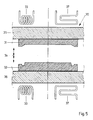
- the supply of heat for melting the heat-activatable material is advantageously done by means of annular heatable press trays 31, 32 which from both sides of a grinding or polishing disc are pressed together around this at least in the area immediately along the folding edge 15 and the central annular portion 12.
- the press trays 31, 32 form part of a press tool 30 of a generally known construction enabling a movement towards and away from each other in the direction in dicated by the arrow 34.
- the two press trays 31, 32 are each attached to a plate 35, 36 which can be fixed in a press.
- the press trays 31, 32 are provided with heating means for heating the trays to a temperature being dependent on the melting temperature of the heat-activatable material 18, said heating means being schematically implied by 33 whereby the heating means may be of any known type.
- the press trays 31, 32 can furthermore be provided with cooling means 37, for instance a heat exchanger through which a coolant, such as water, is passed in order that the material 18 shortly after melting will soon again harden.
- the grinding or polishing device produced by the method according to the invention comprising at least one grinding or polishing disc is highly advantageous to be used for grinding wooden objects, such as particularly profiled wooden objects appearing with depressions and projections that make up a pattern.
- the light segments extending radially will follow the contours of the machined surface, so that it becomes possible to polish a concave surface by means of a polishing disc.
- Segments in such a grinding disc will when grinding workpieces with depressions turn around their longitudinal axis and move outwards towards the bottom of such depressions.
- the grinding disc will thus adapt itself to even very angular surfaces and is so to speak self-adjusting meaning that fine details are not damaged.
- the grinding or polishing can be carried out both before and after lacquering of the wooden surface in that the grinding or polishing is not carried out with the intention of actually removing any material nor of changing the dimension of the workpiece.
- grinding prior to the lacquering merely those fine wood fibres are removed as would otherwise rise by the lacquering and make the dried lacquered surface uneven.
- the consumption of lacquer is highly reduced in that most of the fibres are removed by the grinding, which is why the lacquered surface will appear very smooth even prior to any subsequent grinding. This smooth surface can, however, be further improved by subsequent grinding.
Abstract
The invention relates to a method of producing a grinding or polishing device comprising one or more grinding or polishing discs each formed of a rectangular sheet (1) which from its longitudinal edges (13, 14) is cut to a line (8) a distance from the longitudinal centre line (2), whereafter the sheet (1) is folded on this centre line (2) which is then folded and joined at the centre (10, 11) of the two opposed longitudinal edges (5, 6) for the formation of a central annular portion (12) consisting of two ring halves (13, 14) being joined at a folding edge (15) in that segments (9) produced by the cuts (7) extend radially in substantially two parallel levels (16, 17) from the central annular portion (12) where a string (18) is arranged between the ring halves (13, 14) along the edge of the central annular portion (12).
According to the invention a string of a heat-activatable material (18) is used as string, said string (18) being heated so that it melts at least partially and spreads between tho two ring halves (13, 14) which after cooling of the heat-activatable material are glued together for the formation of a reinforcement area (19) extending radially outwards from the folding edge to the radially innermost end of the segments (9).
The invention also relates to a grinding or polishing device produced according to the method, a tool for carrying out the method, and the use of the grinding or polishing device.
Description
- The invention relates to a method of producing a grinding or polishing device comprising one or more substantially circular grinding or polishing discs each comprising a grinding element formed by a substantially rectangular sheet which in its entire length from a line positioned a distance from the longitudinal centre line of the sheet to the adjacent longitudinal edge is provided with cuts being parallel and at equal distance to each other for the formation of a number of grinding or polishing segments, whereafter the sheet is folded on its centre line so that the segments lie on top of each other, and the centre line is then bent and joined at the centre point of the two opposed end edges for the formation of a central annular portion consisting of two substantially parallel ring halves joined by a folding edge, said ring halves having a circular shape around a central hole, and from which central annular portion the said segments extend radially in substantially two parallel levels, whereafter a string is placed between the ring halves along the edge of the central hole in order that the circular shape of the sheet is maintained.
- Grinding or polishing discs are used as rotating tools of different kinds. Usually the grinding material is provided with abrasive grits but also non-grinding materials are used for removing for instance surface coatings such as rust and similar types of corrosion.
- The grinding or polishing discs are often placed side by side on a spindle whereby they form a grinding or polishing device which on the whole appears as a circular cylinder whose round-going surface is used for grinding or polishing.
- The individual grinding or polishing discs are cut up into segments by cutting up part of the distance from the periphery towards the centre.
- A grinding or polishing disc of the above mentioned type is known from US patent no. 2,879,631. As opposed to the prior art applied by the production of grinding or polishing discs where circular discs were punched from square sheets, whereby the four corners of the square sheet were wasted, this patent teaches the use of a rectangular sheet in order to avoid this waste of material.
- Materials such as steel, plastic or wowen materials are used for these sheets, which materials can for instance be laminate, whereby the sheets depending on their basic material may in themselves be grinding or polishing, or the sheets can be provided with a coating of a grinding material.
- The sheet is cut up in its entire length by a number of cuts being parallel to the end edges for the formation of uniform segments in that the cuts can extend from a line a distance removed from the centre line of the sheet to the adjacent as well as to the opposite side edge. Having been cut, the sheet is folded on its centre line so that the segments lie on top of each other, and the centre of the sheet is then folded and joined at the centre of the two end edges so that a central annular portion is produced consisting of two substantially parallel ring halves being joined at a folding edge and having a circular shape around a central hole from which the segments extend radially in two parallel levels.
- In order to hold together the centre of the two end edges of the sheet so that this known grinding disc can be kept in its circular shape in order for the grinding disc to be placed and held on a spindle so that the grinding disc can be brought to rotate, the folding edge, which holds together the two ring halves along the central hole, is arranged in a channel having a U-shaped cross section, whereafter the two limbs of the U are squeezed axially together against the two opposite sides of the grinding disc.
- In order to ensure a reliable fixture of the two ring halves, the U-shaped channel is provided with flaps which are hit through openings in the sheet.
- These openings in the sheet do of course cause a weakening of the material of the sheet so that the segments comparatively easily are torn off the grinding disc in use.
- It is also possible, however, to keep the sheet in its circular shape by placing a string along the longitudinal centre line of the sheet; if this is the case, it is necessary to bend the limbs of the U-shaped channel towards each other so that they are so to speak are curved around the string.
- This string is probably of metal and it is not stated how the two ends of the string are joined.
- This method of producing a grinding or polishing disc by means of a U-shaped channel involves a considerable increase in cost of the grinding or polishing disc, in that the production of the U-shaped channel and the placing of this on the folded sheet is considerably more expensive than the production of the sheet itself with its segments.
- The use of a U-shaped channel, which by nature must be made of metal, apart from making the grinding or polishing disc more expensive also increases its weight which is a considerable disadvantage of this known grinding or polishing disc when it is to be used in a manually operated tool which usually applies a number of discs on the same spindle so that some kind of a grinding cylinder having a circular surface is formed.
- This weight also has another disadvantage in that it increases the moment of inertia of the grinding or polishing disc so that frequent starts and stops of the disc requires an increase of the necessary tool or machine power.
- A method of producing a grinding or polishing device of the mentioned kind as disclosed in DE published specification no. 31 52 552 is thus an attempt at solving this problem.
- By this known method a string is used having a length corresponding to the length of the sheet, and heat is supplied in order to join the two ends of the string in order thereby to join the centres of the two opposed end edges of the sheet for the formation of the central annular portion having a circular shape around the central hole.
- It has turned out, however, that the grinding or polishing disc produced according to this method is not strong enough to withstand such influences as such a grinding or polishing disc is subjected to in use, because the two ring halves tend to crack along the folding edge just as the hub consisting of the two ring halves do not provide sufficient control of the grinding or polishing disc on a rotating spindle whereby the segments are not held fixedly and are not controlled in a sufficiently reliable manner.
- It is the object of the invention to provide a method of producing a grinding or polishing disc of the mentioned type in order to produce a grinding or polishing disc without the above disadvantages.
- This is achieved by a method of the mentioned type which according to the invention is characteristic in that a string of a heat-activatable material is used as string, and that the string when subjected to heat melts so that the two ring halves are glued together for the formation of a closed ring with a reinforcement area extending radially from the folding edge to the radially innermost end of the segments.
- By proceeding in the provided manner a grinding or polishing disc can be produced which is extremely inexpensive and also very light in that it weighs only slightly more than the sheet itself meaning that a great number of grinding or polishing discs according to the invention can be placed in a manually operated tool requiring only minimum strength of the user.
- By the radial extent occurring as a result of the heat supply, the heat-activatable material creates a reinforcement area which will also hold together the two halves in a reliable and fixed manner and after hardening forms a closed semi-rigid inner ring which makes it easy to fit the ring onto a spindle.
- Moreover, this zone provides a suitably rigid base for the segments which are held in a very secure and reliable manner. All the segments are thus controlled at their base whereby they remain in the same level.
- The above method of joining gives the segments the required rigidity at their base and an increasing ability to yield towards the ends while the fan-shape enables neighbouring and opposite segments to intersect the level being opposite and thus to "curl" at their ends.
- If the sheet is made of metal it is expedient, as presented in
claim 2, to use a soldering string as string which by the effect of heat will melt and solder together the two ring halves. - It will be obvious to any person skilled in the art that the production of the grinding or polishing disc need not necessarily take place in this order.
- Thus, the sheet can first be joined at the centre of the two opposed end edges for the formation of a tube, whereafter a string is placed at the centre of the sheet, which is then folded around the centre for the formation of the central annular portion. In this case it is expedient, as presented in
claim 3, to use an endless ring of string as heat-activatable string in that an immediate fixture of the tubular shape is provided merely by the placement of the ring of string. - It is expedient to supply heat by means of annular heatable press trays which, as presented in
claim 4, are constructed to be able to press the bent and folded parts together in the area around the folding edge while the press trays heat the string so that it melts. - This will ensure that the central annular portion obtains a uniform thickness along the periphery, and that an intimate contact between the heat-activatable material and the ring halves is obtained.
- The invention also relates to a grinding or polishing device produced according to the above method, said grinding or polishing device comprising one or more substantially circular grinding or polishing discs each having a central annular portion formed by two substantially parallel ring halves joined at a folding edge and having a circular shape around a central hole from which a number of grinding segments extend radially outwards in substantially two parallel levels, said grinding or polishing discs according to the invention being characteristic in that a heat-activatable material intimately connected with the ring halves is placed between the two ring halves creating a reinforcement area extending around the folding edge and between this and the radially inner-most end of the grinding segments.
- Such grinding or polishing discs have an extremely light and yet strong hub facilitating an exact centering on a spindle when either one or several discs together are to be arranged in a grinding or polishing device, and the ring halves are fixedly connected to each other so that no cracks will occur along the folding edge which might have become weaker due to the folding. The close joint of the two ring halves also provides a good and reliable control of the segments.
- For certain workpieces it has been found expedient to produce grinding or polishing discs of metal, a factor which makes it expedient, as presented in claim 6, that the heat-activatable material is suited for soldering.
- A grinding or polishing device comprising several grinding or polishing discs which can be arranged on the one and same rotary spindle of a tool is according to the invention characteristic in that the grinding or polishing device comprises a retaining disc which can be fitted between each grinding or polishing disc, said retaining disc either being able to squeeze axially in the reinforcement area or which may be glued on.
- By using such retaining discs the grinding or polishing discs can be held at such an axial distance to each other that the segments have the best possible conditions for adapting themselves to the surface of a workpiece to be ground.
- The invention also relates to a tool for carrying out the method of producing a grinding or polishing disc having a central annular portion consisting of two substantially parallel ring halves being joined at a folding edge and having a circular shape around a central hole, from which a number of grinding segments extend radially outwards in substantially two parallel levels, whereby a heat-activatable material by the method according to the invention is placed between the two ring halves, said tool according to the invention being characteristic in that the tool comprises at least one and a second press tray provided with heating means, said press trays being constructed so that they can be pressed against the axial sides of a grinding or polishing disc and heat both the ring halves as well as the string of heat-activatable material between these so that the string is substantially brought to melt.
- By using the mentioned tool it is partly obtained that the melting of the string is controlled and partly that the subsequent cooling of the string is controlled in such a manner that the produced hub and reinforcement area in a grinding or polishing disc are accurate in relation to the axis of the disc.
- The grinding or polishing device produced by the method according to the invention and having at least one grinding or polishing disc is extremely advantageous when grinding wooden objects, such as particularly profiled wooden objects appearing with depressions and projections that make up a pattern.
- The light segments extending radially will follow the contours of the machined surface, so that it becomes possible to polish a concave surface by means of a polishing disc.
- The segments in such a grinding disc will when grinding workpieces with depressions turn around their longitudinal axis and move outwards towards the bottom of such depressions. The grinding disc will thus adapt itself to even very angular surfaces and is so to speak self-adjusting meaning that fine details are not damaged.
- The grinding or polishing can be carried out both before and after lacquering of the wooden surface in that the grinding or polishing is not carried out with the intention of actually removing any material nor of changing the dimension of the workpiece. When grinding prior to the lacquering, merely those fine wood fibres are removed as would otherwise rise by a lacquering and make the dried lacquered surface uneven. By the preceding grinding, the consumption of lacquer is highly reduced in that most of the fibres are removed by the grinding, which is why the lacquered surface will appear very smooth even prior to any subsequent grinding. This smooth surface can, however, be further improved by subsequent grinding.
- In the following the invention will be explained in further detail with reference to the drawing, where
- Fig.1 shows a sheet with punched out segments,
- Fig. 2 shows the sheet folded on its centre and folded for the formation of a circular grinding or polishing disc,
- Fig. 3 shows the section along III-III in fig. 2 in a grinding or polishing disc,
- Fig.4 shows a grinding or polishing device according to the invention comprising several grinding or polishing discs and retaining discs situated on a rotary spindle where one half is shown in section, and
- Fig.5 shows schematically a tool to be used when carrying out the method according to the invention, said tool comprising a first and a second press tray.
- As shown in fig. 1 the starting point is a
rectangular sheet 1 which can be of a grinding type, such as emery cloth or of a non-grinding type, such as plastic, leather or metal. - The
sheet 1 has alongitudinal centre line 2, twolongitudinal edges end edges 5, 6. In the entire length of thesheet 1parallel cuts 7 are made on both sides of thecentre line 2, saidcuts 7 extending from alongitudinal line 8 positioned a distance from thecentre line 2 and to the neighbouringlongitudinal edge polishing segments 9 of equal length and width are formed. - The
sheet 1 is now folded on thecentre line 2 so that thesegments 9 along the twolongitudinal edges - The
centre 2 of the sheet is then folded and joined at thecentre opposite end edges 5, 6 for the formation of a centralannular portion 12 consisting of two substantiallyparallel ring halves centre line 2 of thesheet 1 in the following referred to as afolding edge 15. The centralannular portion 12 encircles acentral hole 20. Thesegments 9 extend radially outwards from thering halves parallel levels - In order to hold the grinding or polishing disc in its now produced disc-shape, a
string 18 is positioned between the tworing halves string 18 rests on the radially outermost side of thefolding edge 15. - The
string 18 must have a length which is at least equal to the length of thesheet 1 in its longitudinal direction so that the ends of thestring 18 will at least reach each other for obtaining a fixed connection between the ends. Thestring 18 has, however, preferably a length being several times that of thesheet 1, whereby thestring 18 can be wound several times round along the outermost side of thefolding edge 15. - By winding the
string 18 only twice round along thefolding edge 15, the second winding can be brought to squeeze against the first winding so that this is prevented from working loose under the influence of the sheet's 1 tendency to straighten itself whereby thefolding edge 15 would leave its circular shape and become substantially straight, and by winding thestring 18 several times round this squeezing will be further emphasized. - With several windings of the
string 18 round along the outermost side of thefolding edge 15 it will be possible by using athin string 18 to have string material enough to withstand the above tendency of thesheet 1 to straighten, and the outermost winding can temporarily be locked by inserting the free end of thestring 18 below the immediately preceding winding of thestring 18 before this is tightened. - If a different order of forming the disc shape than that mentioned above has been chosen, for instance by first joining the
centre parts sheet 1 into a tubular piece, where thelongitudinal edges sheet 1 form the ends, thesegments 9 extend axially and thecentre line 2 is circumferential at the axial centre of the tubular piece, an endless ring of string can be used asstring 18, said ring being fitted axially around the outside of the tubular piece until the ring of string rests along thecentre line 2, whereafter the ends of the tubular piece, i.e. thesegments 9 are folded radially outwards in relation to the axis of the tubular piece for the formation of the mentioned disc shape. - Irrespective whether the
sheet 1 is folded before or after the formation of the circular ring, thesheet 1 is folded in such a manner that the free ends of thesegments 9 in the oneparallel level segments 9 in the adjacentparallel level segments 9 to turn around their longitudinal axis and turn their grinding material towards the workpiece which is to be ground or polished. - The
string 18 and/or the endless ring of string is of a heat-activatable material. - By supplying heat to the grinding or polishing disc the heat-
activatable string 18 or ring of string will melt and spread between the tworing halves activatable material 18 spreads, whereas part of it, preferably, the major part of it, remains close to the outermost side of thefolding edge 15 for the formation of a strong hub for the disc. - If the
string 18 is wound several times round along the radially outermost side of thefolding edge 15, it is not necessary to supply so much heat to the grinding or polishing disc that the heat-activatable material 18 melts completely. It will thus suffice that the material 18 melts to such a degree that it can spread between the ring halves 13, 14 between thefolding edge 15 and the radially innermost end of thesegments 9, and that thematerial 18 along thefold 15 melts for the formation of a coating layer or membrane which completely surrounds a core of circumferential unmolten strings 18 in that said coating layer or membrane must, however, be melted together with the material 18 arranged between the ring halves 13, 14. - After cooling and hardening of the heat-
activatable material 18 this will glue together the tworing halves reinforcement area 19 which extends all the way round thecentral hole 20 between thefolding edge 15 and the saidline 8 describing the radially innermost end of theslits 7. - Fig. 4 shows a grinding or polishing device according to the invention comprising one or several grinding or polishing discs produced according to the method.
- These grinding or polishing discs are shown placed on a
rotary spindle 21. At the one end of thespindle 21 there is shown astop 22 on which adisc 23 rests. On the side of thedisc 23 turning away from the stop 22 aretaining disc 24 is placed, for instance made of a plastic material. At the side facing thedisc 23 theretaining disc 24 is provided with a hollowing 25 in the centre portion and on the opposite side with ashoulder 26 along the edge. The cross sectional shape is clearly seen in fig. 4. At the places of transition from the hollowing 25, bevelled edges are formed both in theretaining disc 24 and in thedisc 23. - When assembling the grinding or polishing device the retaining
discs 24 and the grinding or polishing discs are placed alternately on thespindle 21. The centralannular portion 12 of the grinding or polishing disc with thefolding edge 15, the ring halves 13, 14 and the heat-activatable material 18 are hereby held fixedly between two retainingdiscs 24. On the outside of thespindle 21 which at its free end is provided with a suitable thread astop disc 27 is arranged having recesses in the side facing the neighbouring retainingdisc 24, so that thisstop disc 27 by means of anut 28 on the thread of thespindle 21 can be tightened against the retainingdiscs 24, the grinding or polishing discs and thedisc 23. - The grinding or polishing discs and the retaining
discs 24 can in this manner be fastened on thespindle 21 so that it all will form part of a rotatable unit. - In order to facilitate the assembly on the
spindle 21 the retainingdiscs 24 can be glued together with the grinding or polishing discs for the formation of a grinding or polishing cylinder which can be inserted on thespindle 21 and fixed by means of thenut 28. - The
spindle 21 can either be arranged on a manual tool which may be operated either by one or both hands, orseveral spindles 21 can form part of an apparatus or machine with mechanical or manual feeding of workpieces to be ground or polished. - The supply of heat for melting the heat-activatable material is advantageously done by means of annular
heatable press trays folding edge 15 and the centralannular portion 12. By this use ofpress trays reinforcement area 19 will to the highest possible degree become uniformly distributed between the ring halves 13, 14. - The
press trays press tool 30 of a generally known construction enabling a movement towards and away from each other in the direction in dicated by thearrow 34. The twopress trays plate press trays activatable material 18, said heating means being schematically implied by 33 whereby the heating means may be of any known type. Thepress trays material 18 shortly after melting will soon again harden. - The grinding or polishing device produced by the method according to the invention comprising at least one grinding or polishing disc is highly advantageous to be used for grinding wooden objects, such as particularly profiled wooden objects appearing with depressions and projections that make up a pattern.
- The light segments extending radially will follow the contours of the machined surface, so that it becomes possible to polish a concave surface by means of a polishing disc.
- Segments in such a grinding disc will when grinding workpieces with depressions turn around their longitudinal axis and move outwards towards the bottom of such depressions. The grinding disc will thus adapt itself to even very angular surfaces and is so to speak self-adjusting meaning that fine details are not damaged.
- The grinding or polishing can be carried out both before and after lacquering of the wooden surface in that the grinding or polishing is not carried out with the intention of actually removing any material nor of changing the dimension of the workpiece. When grinding prior to the lacquering, merely those fine wood fibres are removed as would otherwise rise by the lacquering and make the dried lacquered surface uneven. By the preceding grinding, the consumption of lacquer is highly reduced in that most of the fibres are removed by the grinding, which is why the lacquered surface will appear very smooth even prior to any subsequent grinding. This smooth surface can, however, be further improved by subsequent grinding.
Claims (9)
1. Method of producing a grinding or polishing device comprising one or more substantially circular grinding or polishing discs each comprising a grinding element formed by a substantially rectangular sheet which in its entire length from a line positioned a distance from the longitudinal centre line of the sheet to the adjacent longitudinal edge is provided with cuts being parallel and at equal distance to each other for the formation of a number of grinding or polishing segments, whereafter the sheet is folded on its centre line so that the segments lie on top of each other, and the centre line is then bent and joined at the centre point of the two opposed end edges for the formation of a central annular portion consisting of two substantially parallel ring halves joined by a folding edge, said ring halves having a circular shape around a central hole, and from which central annular portion the said segments extend radially in substantially two parallel levels, whereafter a string is placed between the ring halves along the edge of the central hole in order that the circular shape of the sheet is maintained, characterized in that a string of a heat-activatable material is used as string, and that the string when subjected to heat melts so that the two ring halves are glued together for the formation of a closed annular portion with a reinforcement area extending radially from the folding edge to the radially innermost end of the segments.
2. Method according to claim 1 where a sheet (1) of metal is used, characterized in that a soldering string (18) is used as string (18).
3. Method according to claims 1 and 2, where the sheet (1) is first joined at the centre (10, 11) of the two opposed end edges (5, 6) for the formation of a tubular piece, whereafter a string (18) is placed at the centre (2) of the sheet (1), and the sheet (1) is then folded on the centre (2) for the formation of said central annular portion (12), characterized in that an endless ring of string is used as string (18).
4. Method according to claims 1-3, characterized in that heat is supplied by means of annular heatable press trays designed to press the bent and folded parts together in the area of the folding edge (15) while heating the string (18) so that it melts.
5. Grinding or polishing device comprising one or several substantially circular grinding or polishing discs produced by the method according to claim 1, said grinding or polishing discs each having a central annular portion (12) consisting of two substantially parallel ring halves (13, 14) joined at a folding edge (15), said ring halves (13, 14) having a circular shape around a central hole (20) from which a number of grinding segments (9) extend radially outwards in substantially two parallel levels (16, 17), characterized in that a heat-activatable material (18) being intimately connected with the ring halves (13, 14) is placed between the two ring halves (13, 14) for the formation of a reinforcement area (19) extending along the folding edge (15) and between this (15) and the radially innermost end of the segments (9).
6. Grinding or polishing device according to claim 5 where at least the ring halves (13, 14) are of metal, characterized in that the heat-activa table material (18) is a material suited for soldering.
7. Grinding or polishing device according to claim 5 where there are several grinding or polishing discs which can be arranged on a rotatable spindle (21), characterized in that the grinding or polishing device comprises a retaining disc (24) placed between each grinding or polishing disc, which retaining disc (24) can squeeze axially against the reinforcement area (19).
8. Tool for carrying out the method according to claim 1 of producing the grinding or polishing disc according to claim 5 having a central annular portion (12) consisting of two substantially parallel ring halves (13, 14) joined at a folding edge (15), said ring halves (13, 14) having a circular shape around a central hole (20) from which a number of grinding segments (9) extend radially outwards in substantially two parallel levels (16, 17), characterized in that the tool (30) comprises at least a first (31) and a second press tray (32) provided with heating means (33), said press trays (31, 32) being designed from either side to be moved towards the axial sides of a grinding or polishing disc and heat both the ring halves (13, 14) and a string of a heat-activatable material (18) mounted between these ring halves (13, 14) so that the string is substantially brought to melt.
9. Use of the grinding or polishing device according to claim 5 for grinding and/or polishing pannelled doors, such as doors for furniture or kitchen segments both before and after lacquering said objects.
Priority Applications (1)
| Application Number | Priority Date | Filing Date | Title |
|---|---|---|---|
| EP87850392A EP0320558A1 (en) | 1987-12-18 | 1987-12-18 | Method of producing grinding or polishing device, grinding or polishing device produced according to the method, tool for carrying out the method and use of the grinding or polishing device |
Applications Claiming Priority (1)
| Application Number | Priority Date | Filing Date | Title |
|---|---|---|---|
| EP87850392A EP0320558A1 (en) | 1987-12-18 | 1987-12-18 | Method of producing grinding or polishing device, grinding or polishing device produced according to the method, tool for carrying out the method and use of the grinding or polishing device |
Publications (1)
| Publication Number | Publication Date |
|---|---|
| EP0320558A1 true EP0320558A1 (en) | 1989-06-21 |
Family
ID=8198493
Family Applications (1)
| Application Number | Title | Priority Date | Filing Date |
|---|---|---|---|
| EP87850392A Withdrawn EP0320558A1 (en) | 1987-12-18 | 1987-12-18 | Method of producing grinding or polishing device, grinding or polishing device produced according to the method, tool for carrying out the method and use of the grinding or polishing device |
Country Status (1)
| Country | Link |
|---|---|
| EP (1) | EP0320558A1 (en) |
Cited By (3)
| Publication number | Priority date | Publication date | Assignee | Title |
|---|---|---|---|---|
| US6015334A (en) * | 1996-08-05 | 2000-01-18 | Hh Patent A/S | Method for the deburring of items, particularly items of metal, and use of the method |
| US6234887B1 (en) | 1997-11-03 | 2001-05-22 | Hh Patent A/S | Method for sanding surfaces on items |
| CN113123627A (en) * | 2021-03-05 | 2021-07-16 | 张贤星 | Use supplementary construction equipment of carbon cloth reinforcement crossbeam |
Citations (5)
| Publication number | Priority date | Publication date | Assignee | Title |
|---|---|---|---|---|
| US2680335A (en) * | 1951-12-29 | 1954-06-08 | United Cotton Products Company | Abrading device and method of making |
| US3043063A (en) * | 1958-12-08 | 1962-07-10 | Osborn Mfg Co | Rotary tool |
| WO1982001845A1 (en) * | 1980-11-24 | 1982-06-10 | Keld O Hundebol | Method of forming a grinding or polishing disc and a grinding or polishing implement composed of several such discs |
| GB2169227A (en) * | 1984-12-31 | 1986-07-09 | Hansen & Hundebol | Rotary grinding or polishing device |
| US4615151A (en) * | 1982-12-21 | 1986-10-07 | Tyrolit Schleifmittelwerke Swarovski K.G. | Method for manufacturing of grinding wheel |
-
1987
- 1987-12-18 EP EP87850392A patent/EP0320558A1/en not_active Withdrawn
Patent Citations (5)
| Publication number | Priority date | Publication date | Assignee | Title |
|---|---|---|---|---|
| US2680335A (en) * | 1951-12-29 | 1954-06-08 | United Cotton Products Company | Abrading device and method of making |
| US3043063A (en) * | 1958-12-08 | 1962-07-10 | Osborn Mfg Co | Rotary tool |
| WO1982001845A1 (en) * | 1980-11-24 | 1982-06-10 | Keld O Hundebol | Method of forming a grinding or polishing disc and a grinding or polishing implement composed of several such discs |
| US4615151A (en) * | 1982-12-21 | 1986-10-07 | Tyrolit Schleifmittelwerke Swarovski K.G. | Method for manufacturing of grinding wheel |
| GB2169227A (en) * | 1984-12-31 | 1986-07-09 | Hansen & Hundebol | Rotary grinding or polishing device |
Cited By (4)
| Publication number | Priority date | Publication date | Assignee | Title |
|---|---|---|---|---|
| US6015334A (en) * | 1996-08-05 | 2000-01-18 | Hh Patent A/S | Method for the deburring of items, particularly items of metal, and use of the method |
| CN1076651C (en) * | 1996-08-05 | 2001-12-26 | Hh专利股份有限公司 | Method for deburring itmes, particularly itmes of metal, and use of same |
| US6234887B1 (en) | 1997-11-03 | 2001-05-22 | Hh Patent A/S | Method for sanding surfaces on items |
| CN113123627A (en) * | 2021-03-05 | 2021-07-16 | 张贤星 | Use supplementary construction equipment of carbon cloth reinforcement crossbeam |
Similar Documents
| Publication | Publication Date | Title |
|---|---|---|
| FI71251C (en) | FOERFARANDE FOER FRAMSTAELLNING AV EN SLIP- ELLER POLERINGSSKIVA | |
| US5746863A (en) | Method of making wood tubing | |
| US5020282A (en) | Grinding tool and method of making the same | |
| US6902471B2 (en) | Heavy-duty tool with a rotationally driven, disk-shaped hub | |
| JPH01107962A (en) | Method and device for exchanging one part of tubing | |
| EP0320558A1 (en) | Method of producing grinding or polishing device, grinding or polishing device produced according to the method, tool for carrying out the method and use of the grinding or polishing device | |
| JPH07136937A (en) | Preparation of endless coating abrasive agent article | |
| JPH044108B2 (en) | ||
| US5125192A (en) | Flexible sanding/deburring head | |
| US4882880A (en) | Ganging of buffing wheels | |
| US7056200B2 (en) | Quick change connector for grinding wheel | |
| US5232316A (en) | Hob construction | |
| EP0348846A2 (en) | Balanced-fan rotor and method and apparatus for realising the balancing | |
| WO2002018102A1 (en) | Polishing tool | |
| US20020040656A1 (en) | Method and apparatus for the production of a cylindrical embossing sheet | |
| US3451093A (en) | Cartridge work wheel | |
| US6551180B2 (en) | Grinding tool | |
| EP1068048A1 (en) | Plated grinding tool | |
| US6299518B1 (en) | Rotary abrasion device | |
| US2755608A (en) | Buffing tool | |
| US4212187A (en) | Method and apparatus for resizing torque converter impeller drive shafts | |
| US6595842B2 (en) | Abrasive pad and method of making same | |
| EP0357382A2 (en) | Screen cylinder and method of manufacture | |
| IE910063A1 (en) | A method for seam welding | |
| NZ213537A (en) | Grinding or polishing disc: grinding surface made up of radial "petals" |
Legal Events
| Date | Code | Title | Description |
|---|---|---|---|
| PUAI | Public reference made under article 153(3) epc to a published international application that has entered the european phase |
Free format text: ORIGINAL CODE: 0009012 |
|
| 17P | Request for examination filed |
Effective date: 19881219 |
|
| AK | Designated contracting states |
Kind code of ref document: A1 Designated state(s): AT BE CH DE ES FR GB GR IT LI LU NL SE |
|
| 17Q | First examination report despatched |
Effective date: 19901023 |
|
| STAA | Information on the status of an ep patent application or granted ep patent |
Free format text: STATUS: THE APPLICATION IS DEEMED TO BE WITHDRAWN |
|
| 18D | Application deemed to be withdrawn |
Effective date: 19910629 |