EP0319306B1 - Environmental sealing - Google Patents
Environmental sealing Download PDFInfo
- Publication number
- EP0319306B1 EP0319306B1 EP19880311407 EP88311407A EP0319306B1 EP 0319306 B1 EP0319306 B1 EP 0319306B1 EP 19880311407 EP19880311407 EP 19880311407 EP 88311407 A EP88311407 A EP 88311407A EP 0319306 B1 EP0319306 B1 EP 0319306B1
- Authority
- EP
- European Patent Office
- Prior art keywords
- substrate
- astm
- sealing
- container
- cone penetration
- Prior art date
- Legal status (The legal status is an assumption and is not a legal conclusion. Google has not performed a legal analysis and makes no representation as to the accuracy of the status listed.)
- Expired - Lifetime
Links
- 238000007789 sealing Methods 0.000 title claims description 11
- 230000007613 environmental effect Effects 0.000 title description 9
- 239000000463 material Substances 0.000 claims description 85
- 239000000758 substrate Substances 0.000 claims description 46
- 239000003566 sealing material Substances 0.000 claims description 39
- 238000000034 method Methods 0.000 claims description 25
- 230000035515 penetration Effects 0.000 claims description 17
- 238000001125 extrusion Methods 0.000 claims description 9
- 239000002245 particle Substances 0.000 claims description 8
- 238000010008 shearing Methods 0.000 claims description 5
- 229920001296 polysiloxane Polymers 0.000 claims description 3
- 229920002635 polyurethane Polymers 0.000 claims description 3
- 239000004814 polyurethane Substances 0.000 claims description 3
- 239000012634 fragment Substances 0.000 claims description 2
- 238000003801 milling Methods 0.000 claims description 2
- 239000011243 crosslinked material Substances 0.000 claims 1
- 239000000499 gel Substances 0.000 description 29
- 239000002904 solvent Substances 0.000 description 10
- 238000009434 installation Methods 0.000 description 5
- 230000000694 effects Effects 0.000 description 4
- 239000007788 liquid Substances 0.000 description 4
- 239000000203 mixture Substances 0.000 description 4
- 238000003860 storage Methods 0.000 description 4
- ZWEHNKRNPOVVGH-UHFFFAOYSA-N 2-Butanone Chemical compound CCC(C)=O ZWEHNKRNPOVVGH-UHFFFAOYSA-N 0.000 description 3
- KFZMGEQAYNKOFK-UHFFFAOYSA-N Isopropanol Chemical compound CC(C)O KFZMGEQAYNKOFK-UHFFFAOYSA-N 0.000 description 3
- 239000002480 mineral oil Substances 0.000 description 3
- 230000008569 process Effects 0.000 description 3
- 238000004611 spectroscopical analysis Methods 0.000 description 3
- 235000015112 vegetable and seed oil Nutrition 0.000 description 3
- 239000008158 vegetable oil Substances 0.000 description 3
- 239000004606 Fillers/Extenders Substances 0.000 description 2
- 230000008859 change Effects 0.000 description 2
- 230000006835 compression Effects 0.000 description 2
- 238000007906 compression Methods 0.000 description 2
- 238000011065 in-situ storage Methods 0.000 description 2
- 235000010446 mineral oil Nutrition 0.000 description 2
- 239000004014 plasticizer Substances 0.000 description 2
- 239000000725 suspension Substances 0.000 description 2
- 229910001369 Brass Inorganic materials 0.000 description 1
- 239000004831 Hot glue Substances 0.000 description 1
- 229910000831 Steel Inorganic materials 0.000 description 1
- 239000000654 additive Substances 0.000 description 1
- 239000000853 adhesive Substances 0.000 description 1
- 230000001070 adhesive effect Effects 0.000 description 1
- 238000005054 agglomeration Methods 0.000 description 1
- 230000002776 aggregation Effects 0.000 description 1
- 239000003963 antioxidant agent Substances 0.000 description 1
- PASDCCFISLVPSO-UHFFFAOYSA-N benzoyl chloride Chemical compound ClC(=O)C1=CC=CC=C1 PASDCCFISLVPSO-UHFFFAOYSA-N 0.000 description 1
- 239000010951 brass Substances 0.000 description 1
- 239000000356 contaminant Substances 0.000 description 1
- 230000007797 corrosion Effects 0.000 description 1
- 238000005260 corrosion Methods 0.000 description 1
- 238000009826 distribution Methods 0.000 description 1
- 239000000417 fungicide Substances 0.000 description 1
- 238000001879 gelation Methods 0.000 description 1
- 239000012943 hotmelt Substances 0.000 description 1
- 238000002347 injection Methods 0.000 description 1
- 239000007924 injection Substances 0.000 description 1
- 229910052500 inorganic mineral Inorganic materials 0.000 description 1
- 239000011344 liquid material Substances 0.000 description 1
- 230000005923 long-lasting effect Effects 0.000 description 1
- 229940032007 methylethyl ketone Drugs 0.000 description 1
- 239000003921 oil Substances 0.000 description 1
- 235000019198 oils Nutrition 0.000 description 1
- 239000003973 paint Substances 0.000 description 1
- 239000000049 pigment Substances 0.000 description 1
- 239000002243 precursor Substances 0.000 description 1
- 238000002360 preparation method Methods 0.000 description 1
- 238000003825 pressing Methods 0.000 description 1
- 230000009467 reduction Effects 0.000 description 1
- 238000005096 rolling process Methods 0.000 description 1
- 239000000243 solution Substances 0.000 description 1
- 239000010959 steel Substances 0.000 description 1
- 239000000375 suspending agent Substances 0.000 description 1
- 239000012815 thermoplastic material Substances 0.000 description 1
- 230000009974 thixotropic effect Effects 0.000 description 1
- 230000001052 transient effect Effects 0.000 description 1
- 125000005591 trimellitate group Chemical group 0.000 description 1
- XLYOFNOQVPJJNP-UHFFFAOYSA-N water Substances O XLYOFNOQVPJJNP-UHFFFAOYSA-N 0.000 description 1
Images


Classifications
-
- H—ELECTRICITY
- H02—GENERATION; CONVERSION OR DISTRIBUTION OF ELECTRIC POWER
- H02G—INSTALLATION OF ELECTRIC CABLES OR LINES, OR OF COMBINED OPTICAL AND ELECTRIC CABLES OR LINES
- H02G1/00—Methods or apparatus specially adapted for installing, maintaining, repairing or dismantling electric cables or lines
- H02G1/14—Methods or apparatus specially adapted for installing, maintaining, repairing or dismantling electric cables or lines for joining or terminating cables
-
- H—ELECTRICITY
- H01—ELECTRIC ELEMENTS
- H01R—ELECTRICALLY-CONDUCTIVE CONNECTIONS; STRUCTURAL ASSOCIATIONS OF A PLURALITY OF MUTUALLY-INSULATED ELECTRICAL CONNECTING ELEMENTS; COUPLING DEVICES; CURRENT COLLECTORS
- H01R4/00—Electrically-conductive connections between two or more conductive members in direct contact, i.e. touching one another; Means for effecting or maintaining such contact; Electrically-conductive connections having two or more spaced connecting locations for conductors and using contact members penetrating insulation
- H01R4/70—Insulation of connections
-
- H—ELECTRICITY
- H01—ELECTRIC ELEMENTS
- H01R—ELECTRICALLY-CONDUCTIVE CONNECTIONS; STRUCTURAL ASSOCIATIONS OF A PLURALITY OF MUTUALLY-INSULATED ELECTRICAL CONNECTING ELEMENTS; COUPLING DEVICES; CURRENT COLLECTORS
- H01R43/00—Apparatus or processes specially adapted for manufacturing, assembling, maintaining, or repairing of line connectors or current collectors or for joining electric conductors
- H01R43/005—Apparatus or processes specially adapted for manufacturing, assembling, maintaining, or repairing of line connectors or current collectors or for joining electric conductors for making dustproof, splashproof, drip-proof, waterproof, or flameproof connection, coupling, or casing
Definitions
- the present invention relates to environmental sealing of substrates in the electrical, electronics, telecommunications, power and related industries, particularly to sealing of electrical terminals or other contacts and wire splices.
- an environmental seal may be provided in many ways.
- the substrate to be sealed may be sealed by surrounding it with some sealed box or other enclosure, it may be tape wrapped, it may be painted or it may be coated or surrounded with bulk sealing composition.
- the present invention is preferably concerned with this last category.
- Such sealing may be provided to protect the substrate from various contaminants, and in the case of electrical contacts particularly from water.
- a thermoplastic material such as a hot-melt adhesive
- a curable composition that in its pre-cured state has a low viscosity allowing it to be poured in place around the substrate, after which it is caused to cure.
- dimensionally heat-recoverable articles are used to provide rugged, long-lasting environmental seals.
- Such an article may be supplied in an expanded, enlarged, form in which it is positioned loosely around the substrate and then heated to cause it to shrink into tight engagement with the substrate.
- United States Patent US-A-4,634,207 discloses an apparatus for protecting a substrate, comprising
- Also disclosed is a process for protecting a substrate comprising the steps of: pressing together a substrate to be protected and an apparatus comprising a support member, a gel located on the support member, the gel being cured prior to coming into contact with any part of the substrate, the gel having a cone penetration value of 100 to 350 (10 ⁇ 1 mm) and an ultimate elongation of at least 200%, and means for deforming the gel into close and conforming contact with the substrate, the apparatus and the substrate being pressed together so that the gel contacts the substrate and is deformed into close and conforming contact therewith.
- sealing materials for environmental protection is also disclosed in the following patents: US-A-4,643,924 (Uken et al.), US-A-4,690,831 (Uken et al.), US-A-4,581,265 (Follette), US-A-4,610,910 (Follette), US-A-4,610,738 (Jervis), US-A-4,600,804 (Howard), US-A-4,701,574 (Shimirak), USSN 901,971 filed 29 August 1986 (Dubrow) equivalent to EP-A-0194872, USSN 859,171 filed 29 May 1986 (Kayser) equivalent to EP-A-0225370, US-A-4,662,692 (Uken et al.), US-A-4,647,717 (Uken), USSN 767,555 (Story) filed 20 August 1985 equivalent to EP-A-0213874, USSN 801,018 (Gamarra) filed 22 November 1985 equivalent to EP-A-02243
- EP-A-0246855 discloses articles and methods for surface protection which employ a layer of a gel material and a covering layer of a flexible material which is flexible when installed on the surface to be protected and is hardenable or curable so that after installation the covering layer hardens to hold the gel layer in position and protect the gel layer from mechanical and other environmental conditions.
- Cone penetration values in the above-mentioned specifications are unless the context otherwise requires or states, and are in this specification, expressed in units of 10 ⁇ 1 mm and are measured by ASTM D217-68 at 21° C (70° F) on an undisturbed sample using a standard 1:1 scale cone (cone weight 102.5 g, shaft weight 47.5 g), the penetration being measured after 5 seconds.
- Ultimate elongation values in the above-mentioned specifications are unless the context otherwise requires or states, and are in this specification, as measured according to the technique of ASTMD 638-80 at 21° C (70° F) using a type 4 die to cut the sample and at a speed of 50 cm/minute.
- the invention provides a method of environmentally sealing a substrate, which comprises:
- the mechanical deformation may be carried out in the presence of a solvent such as methyl-ethyl ketone, but this may cause the material to swell with the risk of significant subsequent shrinkage.
- a suspending medium that is not a solvent for the material may be used, an example being isopropyl alcohol.
- the material be processed to produce a smooth, generally homogeneous suspension/solution.
- the resulting material may be thixotropic.
- the solvent or suspending medium may be volatile liquid.
- the mechanical deformation preferably has the effect of breaking a cross-linked network of the material to create a suspension of gel or other particles. Deformation is preferably carried out in a mill, for example using steel rollers set to a gap of say from 0,01270-0,0254 mm (0.0005-0.001 inch), preferably 0,00254-0,01270 mm (0.0001-0.0005 inch).
- the material may be deformed by chopping with a blade or a wire.
- the deformation is preferably a shear process and the material and the shear process are preferably such that substantially no shear heat is generated.
- the sealing material is preferably at least partially cross-linked, for example at least 0.01 to 6 cross-link per weight average molecule, more preferably 0.5 to 4, especially 0.5 to 2 cross-links.
- the material may be cross-linked before or after it is deformed.
- a container may be provided around the substrate, into which the material is directed, preferably by extrusion from a material-dispensing gun, for example of the general type known as a grease-gun.
- the material may be extruded or otherwise directed into the container, and the container with the material then positioned around the substrate.
- the sealing material flows (for example by folding or rolling) around the substrate causing it to be covered in a most satisfactory way. This may be compared to the covering that is achieved with similar gel materials that have not undergone shear. In that case the material appears to have a skin that first stretches and finally breaks, but even then the material may not properly squeeze back over the substrate without excessive trapping or air.
- Shear preferably causes the material to be fragmented, which may be regarded as causing comminution, fracture, or brecciation, or chopping, depending on the size and size distribution of resulting particles. Small particles are preferred.
- the mechanical deformation of the material is preferably carried out by forcing it through a mesh.
- the effect of deformation of the material may be regarded as comminution. Its flow properties are thereby improved.
- the resulting material may be regarded as an agglomeration of particles, each comprising a cross-linked network containing an uncross-linked or liquid component, the particles being loosely interconnected by adhering together, possibly by autoadhesion.
- the material Before the mechanical deformation the material may be regarded as a single cross-linked network containing the uncross-linked or liquid component. This change may be reflected in an increase in it's G'' value, G'' being its loss modulus as determined by dynamic spectroscopy.
- the material may then be directed as desired by extrusion etc. Accordingly preferred methods of the invention involve deforming the material in such a way as to increase its 'G' value.
- the invention therefore also provides a method of producing a sealing material which comprises:
- Compression preferably occurs during extrusion, and this can be enhanced by correct choice of extrusion nozzle size and nozzle-land length.
- the invention also provides a sealing material which has:
- Stress relaxation is to be performed at 23° C for 1 hour using a dynamic spectrometer (such as Rheometrics RDS-770, trade mark) in the transient parallel plate mode.
- the stress relaxation time is therefore the time at which the stress relaxation ratio is equal to e-1, ie. 0.368; e-1 describing the exponential decay of an idealized stress relaxation curve.
- the sealing material has a stress relaxation time of less than 800 seconds, more preferably less than 700 seconds, particularly less than 500 seconds.
- Sealing material may be supplied in any convenient way.
- the material may be extruded from a material-dispensing gun, and the invention therefore further provides a cartridge (optionally a disposable cartridge) having therein a cured material having an ultimate elongation of at least 100% according to ASTM D638-80 and a cone penetration value of 150-350 (10 ⁇ 1 mm).
- the sealing material may be supplied in a device that provides one or more of the following:
- the sealing material of the invention or used in a method or article of the invention preferably has one or more of the following properties.
- the cone penetration of the material before use is preferably greater than 100, more preferably greater than 150, particularly greater than 170, especially greater than 200 (10 ⁇ 1 mm) It is preferably less than 400, more preferably less than 350, especially less than 300 (10 ⁇ 1 mm).
- the ultimate elongation of the material before use is preferably greater than 50%, more preferably greater than 100, particularly greater than 200%, more particularly greater than 300%.
- Storage modulus of the material before use is determined by dynamic spectroscopy (using for example a Rheometrics RDS-7700, trade mark) measured at 24° C on a 25 mm diameter disc at 1 Hz frequency.
- G′ is preferably less than 107 dynes/cm2, more preferably less than 5x10⁶ dynes/cm2, particularly less than 106 dynes/cm2, especially less than 5x10⁵ dynes/cm2.
- Tan delta of the material before use is the ratio between the loss modulus (G ⁇ ) and the storage modulus (G′), each in dynes/cm2, each determined by dynamic spectroscopy. Tan delta is preferably less than 1, ie. the storage modulus is preferably greater than the loss modulus More preferably tan delta is less than 0.8, particularly less than 0.7.
- this is preferably less than 900 seconds, more preferably less than 700 seconds, particularly less than 500 seconds, especially less than 200 seconds. Preferably it is greater than 10 seconds, particularly greater than 50 seconds. It is desirable that the material relax as fast as possible initially (so that the material can easily surround a substrate) and then not relax further, so that it can be put and remain under compression.
- the sealing material before and after deformation is preferably tacky, more preferably has high tack.
- the means for mechanically deforming and for dispensing the sealing material preferably have one or more of the following characteristics.
- the material and the means for dispensing are preferably such that the material can be dispensed under a pressure of less than 3000 psi, more preferably less than 2000 psi.
- the material and the means for dispensing are preferably such that the material can be dispensed under a pressure of less than 100 psi, more preferably less than 50 psi, particularly less than 20 psi, particularly less than 10 psi.
- the flow rate of the material from the means for dispensing is preferably greater than 0.01 grams per second, more preferably greater than 0.1 grams per second, particularly greater than 1.0 grams per second, especially greater than 10 grams per second.
- the means for deforming the material is preferably a mesh, grid or other perforate structure.
- the structure is, or is equivalent to, the size of 50 mesh (holes per inch) or finer, more preferably 70 mesh or finer, particularly 100 mesh or finer, more particularly 150 mesh or finer.
- the material may be extruded through a nozzle of diameter greater than 0.075 cm, preferably greater than 0.1 cm, preferably greater than 0.2 cm. A smaller nozzle helps to stick the particles of comminuted material back together.
- the nozzle land preferably has a length of at least 1 cm, more preferably at least 2 cm, particularly at least 3 cm.
- the land through which the material passes after deformation helps to cause pressure or flow orientation or gives the material time to relax some of its original memory before pressure reduction.
- Figure 1 shows a material dispensing gun containing a sealing material that has been subjected to milling in the presence of a solvent or suspending agent.
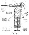
- Figure 2 shows a material dispensing gun containing a sealing material.
- the gun has a mesh through which the sealing material can be forced to deform it mechanically, for example by shear.
- the gun also has a nozzle.
- Figure 3 shows a terminal block having brass connection posts and a connecting bar that require corrosion protection. It can be difficult with prior art gels to obtain good protection under the connecting bar and under undercuts on the terminal posts.
- sealing material can be directly extruded under the bar, or can be first placed in a container (illustrated to the right of the connecting block) and the container then placed over the terminals and bar.
- Figure 4 shows a connector that may be part of an automobile wiring system.
- An array of wires (say six by three) exit from a waffle-shaped connector back.
- a cover (illustrated to the right of the connector back) can be pre-filled with sealing material, or can be positioned over the connector back and then filled with sealing material.
- An air release hole may be provided to aid filing.
- a cover can be provided having two holes; one for injection of sealing material and the other for release of air.
- the sealing material is usually electrically insulating (ie. has a resistivity of at least 109 ohm.cm), but is not necessarily so for some possible uses of the invention, eg. when non-electrical substrates are being protected.
- Suitable sealing materials include materials made by gelling curable polyurethane precursor materials (as described for example in the patents referenced above in the presence of substantial quantities of a mineral oil, a vegetable oil or a plasticizer, or a mixture of two or more of these.
- Suitable sealing materials can also be prepared by curing reactive silicones with non-reactive extender silicones, and the invention includes the use of any sealing material having the desired cone penetration and elongation values.
- the sealing material may contain known additives such as moisture scavengers (e.g. benzoyl chloride), antioxidants, pigments and fungicides.
- the sealing material is preferably hydrolytically stable, moisture-insensitive, and substantially inert towards the substrate.
Landscapes
- Engineering & Computer Science (AREA)
- Manufacturing & Machinery (AREA)
- Sealing Material Composition (AREA)
- Manufacturing Of Electrical Connectors (AREA)
- Connector Housings Or Holding Contact Members (AREA)
Description
- The present invention relates to environmental sealing of substrates in the electrical, electronics, telecommunications, power and related industries, particularly to sealing of electrical terminals or other contacts and wire splices.
- An environmental seal may be provided in many ways. For example, the substrate to be sealed may be sealed by surrounding it with some sealed box or other enclosure, it may be tape wrapped, it may be painted or it may be coated or surrounded with bulk sealing composition. The present invention is preferably concerned with this last category. Such sealing may be provided to protect the substrate from various contaminants, and in the case of electrical contacts particularly from water.
- A problem arises in providing environmental protection due to an inherent conflict between the desire for ease of installation of the sealing means, and tightness of the final seal. This problem is often overcome by having the sealing means undergo some change in physical condition, for example a paint may be applied as a liquid that subsequently solidifies. An alternative is the provision of a thermoplastic material, such as a hot-melt adhesive, that may be softened or melted and then applied to the substrate and allowed to solidify. Another example is a curable composition that in its pre-cured state has a low viscosity allowing it to be poured in place around the substrate, after which it is caused to cure.
- For many applications dimensionally heat-recoverable articles are used to provide rugged, long-lasting environmental seals. Such an article may be supplied in an expanded, enlarged, form in which it is positioned loosely around the substrate and then heated to cause it to shrink into tight engagement with the substrate.
- Recently it has been proposed to provide an environmental seal by means of a sealing material that is supplied pre-cured in some form of container which is then fixed relative to the substrate so that the sealing material is held under pressure against a surface of the substrate to be sealed. This technique may be contrasted with one where a sealing material in an uncured form is poured into a container to surround the substrate and is then cured in situ. Pre-curing has many advantages, particularly ease and speed of installation in the field.
- An apparatus for providing environmental sealing in this way is disclosed and claimed in United States Patent US-A-4,600,261 (Debbaut). That patent discloses a protection apparatus comprising:
- (a) an insulating gel characterized by
- (1) a cone penetration value from approximately 150-350 (10⁻¹ mm);
- (2) an ultimate elongation of at least approximately 200%;
- (3) a maximum tensile strength of approximately 20 psi;
- (4) a cohesive strength greater than its adhesive strength;
- (b) first means to contain said gel;
- (c) second means to retain said gel within said first means; and
- (d) force means which acts on said first means so that said gel is maintained in compressive contact with said electrical contact and substantially encapsulates a conductive portion of said electrical contact, whereby upon release of said force means and a disengagement of said first means from said electrical contact, said gel remains substantially within said first means.
- United States Patent US-A-4,634,207 discloses an apparatus for protecting a substrate, comprising
- (a) a gel, the gel being cured prior to coming into contact with any part of the substrate to be protected, the gel having a cone penetration value of 100-350 (10⁻¹ mm) and an ultimate elongation of at least 200%; and
- (b) means for deforming the gel into close and conforming contact with the substrate.
- Also disclosed is a process for protecting a substrate, comprising the steps of:
pressing together a substrate to be protected and an apparatus comprising a support member, a gel located on the support member, the gel being cured prior to coming into contact with any part of the substrate, the gel having a cone penetration value of 100 to 350 (10⁻¹ mm) and an ultimate elongation of at least 200%, and means for deforming the gel into close and conforming contact with the substrate, the apparatus and the substrate being pressed together so that the gel contacts the substrate and is deformed into close and conforming contact therewith. - The use of sealing materials for environmental protection is also disclosed in the following patents: US-A-4,643,924 (Uken et al.), US-A-4,690,831 (Uken et al.), US-A-4,581,265 (Follette), US-A-4,610,910 (Follette), US-A-4,610,738 (Jervis), US-A-4,600,804 (Howard), US-A-4,701,574 (Shimirak), USSN 901,971 filed 29 August 1986 (Dubrow) equivalent to EP-A-0194872, USSN 859,171 filed 29 May 1986 (Kayser) equivalent to EP-A-0225370, US-A-4,662,692 (Uken et al.), US-A-4,647,717 (Uken), USSN 767,555 (Story) filed 20 August 1985 equivalent to EP-A-0213874, USSN 801,018 (Gamarra) filed 22 November 1985 equivalent to EP-A-0224389, and USSN 945,219 (Chang) filed 22 December 1986 equivalent to EP-A-0174165.
- EP-A-0246855 (Raychem) discloses articles and methods for surface protection which employ a layer of a gel material and a covering layer of a flexible material which is flexible when installed on the surface to be protected and is hardenable or curable so that after installation the covering layer hardens to hold the gel layer in position and protect the gel layer from mechanical and other environmental conditions.
- Cone penetration values in the above-mentioned specifications are unless the context otherwise requires or states, and are in this specification, expressed in units of 10⁻¹ mm and are measured by ASTM D217-68 at 21° C (70° F) on an undisturbed sample using a standard 1:1 scale cone (cone weight 102.5 g, shaft weight 47.5 g), the penetration being measured after 5 seconds.
- Ultimate elongation values in the above-mentioned specifications are unless the context otherwise requires or states, and are in this specification, as measured according to the technique of ASTMD 638-80 at 21° C (70° F) using a type 4 die to cut the sample and at a speed of 50 cm/minute.
- A problem can arise in difficult circumstances with the above prior art sealing material (referred to in general terms herein as a "gel") and/or above prior art methods. That problem may arise where the substrate is of a complex shape since it may then be difficult to cause the gel fully to cover all surfaces of the substrate by forcing against the substrate a gel pre-cured or case in a container. This is likely to be the case where the substrate is deep and must therefore penetrate a great distance into the gel, or where the substrate comprises many wires around which the gel must be caused to flow.
- An alternative to pouring a liquid material around the substrate and then curing is likely to be unacceptable because it is impractical, time consuming and may result in the release of undesirable gasses during curing. The use of a hot-melt sealing material is frequency impractical due to the amount of heat required, and consequent possible damage to the substrate.
- We have now found that this problem of installation of materials of the general type referred to as gels can be overcome by subjecting the material to mechanical deformation prior to use optionally in the presence of a suitable solvent or extender or suspending medium. This then allows the material to be directed to the position where it is required, by for example extrusion through a nozzle. The step of extrusion itself may provide the desired mechanical deformation. We have found that the flow properties of the material may be suitably altered by this deformation, but that it may be able, where necessary, afterwards to cohere or to "knit" back together again, retaining a sufficient ultimate elongation or other property required during its service life.
- Thus, the invention provides a method of environmentally sealing a substrate, which comprises:
- (a) providing (preferably at ambient temperature) a sealing material having an ultimate elongation according to ASTMD 638-80 of at least 100%, preferably 200%, and a cone penetration according to ASTM D217-68 at 21° C of greater than 100 (10⁻¹ mm);
- (b) subjecting (preferably at ambient temperature) the material to a shearing force; and
- (c) then causing (preferably at ambient temperature) the material to flow over the surface of the substrate;
- The mechanical deformation may be carried out in the presence of a solvent such as methyl-ethyl ketone, but this may cause the material to swell with the risk of significant subsequent shrinkage. Thus, for many uses a suspending medium that is not a solvent for the material may be used, an example being isopropyl alcohol. In any case, I prefer that the material be processed to produce a smooth, generally homogeneous suspension/solution. The resulting material may be thixotropic. The solvent or suspending medium may be volatile liquid. In this embodiment, the mechanical deformation preferably has the effect of breaking a cross-linked network of the material to create a suspension of gel or other particles. Deformation is preferably carried out in a mill, for example using steel rollers set to a gap of say from 0,01270-0,0254 mm (0.0005-0.001 inch), preferably 0,00254-0,01270 mm (0.0001-0.0005 inch).
- As an alternative to a mill, the material may be deformed by chopping with a blade or a wire.
- In all embodiments the deformation is preferably a shear process and the material and the shear process are preferably such that substantially no shear heat is generated.
- The sealing material is preferably at least partially cross-linked, for example at least 0.01 to 6 cross-link per weight average molecule, more preferably 0.5 to 4, especially 0.5 to 2 cross-links. The material may be cross-linked before or after it is deformed.
- A container may be provided around the substrate, into which the material is directed, preferably by extrusion from a material-dispensing gun, for example of the general type known as a grease-gun. Alternatively, the material may be extruded or otherwise directed into the container, and the container with the material then positioned around the substrate. We have found surprisingly that when the container is thus positioned with respect to the substrate, the sealing material flows (for example by folding or rolling) around the substrate causing it to be covered in a most satisfactory way. This may be compared to the covering that is achieved with similar gel materials that have not undergone shear. In that case the material appears to have a skin that first stretches and finally breaks, but even then the material may not properly squeeze back over the substrate without excessive trapping or air.
- The effect of shear in allowing such materials to be directed by extrusion or otherwise, but to retain their elongation or elastic memory or other properties, was quite unexpected. Also unexpected was the effect of shear in improving the ability of such materials prepositioned in a container to be deformed around a substrate. Shear preferably causes the material to be fragmented, which may be regarded as causing comminution, fracture, or brecciation, or chopping, depending on the size and size distribution of resulting particles. Small particles are preferred.
- In the absence of the solvent or suspending medium, the mechanical deformation of the material is preferably carried out by forcing it through a mesh.
- The effect of deformation of the material, whether in the presence or absence of a solvent or suspending medium, may be regarded as comminution. Its flow properties are thereby improved. In the case of gels as referred to above, the resulting material may be regarded as an agglomeration of particles, each comprising a cross-linked network containing an uncross-linked or liquid component, the particles being loosely interconnected by adhering together, possibly by autoadhesion. Before the mechanical deformation the material may be regarded as a single cross-linked network containing the uncross-linked or liquid component. This change may be reflected in an increase in it's G'' value, G'' being its loss modulus as determined by dynamic spectroscopy. The material may then be directed as desired by extrusion etc. Accordingly preferred methods of the invention involve deforming the material in such a way as to increase its 'G' value.
- The invention therefore also provides a method of producing a sealing material which comprises:
- (a) providing a material having an ultimate elongation according to ASTM D638-80 of at least 100% a cone penetration according to ASTM D217-68 at 21° C of greater than 100 (10⁻¹ mm); and
- (b) deforming the material;
- (c) so that the deforming force is a shear force greater than the ultimate cohesive strength of the material which fragments the material, and the method additionally comprises compressing the material to cause the fragmented particles to adhere together.
- Compression preferably occurs during extrusion, and this can be enhanced by correct choice of extrusion nozzle size and nozzle-land length.
- We have found also that advantageous sealing materials, particularly for the installation techniques disclosed herein, have a lower stress relaxation than that of otherwise similar prior art gel.
- Thus, the invention also provides a sealing material which has:
- (a) an ultimate elongation according to ASTM D638-80 of at least 100%;
- (b) a cone penetration value of at least 150 (10⁻¹ mm); and
- (c) a stress relaxation time, being the time at which the stress relaxation ratio is e-1, of less than 900 seconds.
- Stress relaxation is to be performed at 23° C for 1 hour using a dynamic spectrometer (such as Rheometrics RDS-770, trade mark) in the transient parallel plate mode. A stress relaxation ratio may be deformed as the ratio of the stress, or modulus, G(T), at time t divided by peak stress achieved when the strain is applied at time t=0. The stress relaxation time is therefore the time at which the stress relaxation ratio is equal to e-1, ie. 0.368; e-1 describing the exponential decay of an idealized stress relaxation curve.
- We prefer that the sealing material has a stress relaxation time of less than 800 seconds, more preferably less than 700 seconds, particularly less than 500 seconds.
- Sealing material may be supplied in any convenient way. For some uses the material may be extruded from a material-dispensing gun, and the invention therefore further provides a cartridge (optionally a disposable cartridge) having therein a cured material having an ultimate elongation of at least 100% according to ASTM D638-80 and a cone penetration value of 150-350 (10⁻¹ mm).
- The sealing material may be supplied in a device that provides one or more of the following:
- (a) means for containing the material prior to use;
- (b) means for physically deforming the material by shear or otherwise;
- (c) means for directing the material by extrusion or otherwise to its desired position;
- (d) means for locating the material around a substrate to be protected; and
- (e) means for maintaining the sealing material under pressure against a surface of the substrate.
- The sealing material of the invention or used in a method or article of the invention preferably has one or more of the following properties.
- The cone penetration of the material before use is preferably greater than 100, more preferably greater than 150, particularly greater than 170, especially greater than 200 (10⁻¹ mm) It is preferably less than 400, more preferably less than 350, especially less than 300 (10⁻¹ mm).
- The ultimate elongation of the material before use is preferably greater than 50%, more preferably greater than 100, particularly greater than 200%, more particularly greater than 300%.
- Storage modulus of the material before use is determined by dynamic spectroscopy (using for example a Rheometrics RDS-7700, trade mark) measured at 24° C on a 25 mm diameter disc at 1 Hz frequency. G′ is preferably less than 107 dynes/cm2, more preferably less than 5x10⁶ dynes/cm2, particularly less than 106 dynes/cm2, especially less than 5x10⁵ dynes/cm2.
- Tan delta of the material before use is the ratio between the loss modulus (G˝) and the storage modulus (G′), each in dynes/cm2, each determined by dynamic spectroscopy. Tan delta is preferably less than 1, ie. the storage modulus is preferably greater than the loss modulus More preferably tan delta is less than 0.8, particularly less than 0.7.
-
- For the material after deformation, this is preferably less than 900 seconds, more preferably less than 700 seconds, particularly less than 500 seconds, especially less than 200 seconds. Preferably it is greater than 10 seconds, particularly greater than 50 seconds. It is desirable that the material relax as fast as possible initially (so that the material can easily surround a substrate) and then not relax further, so that it can be put and remain under compression.
- The sealing material before and after deformation is preferably tacky, more preferably has high tack.
- The means for mechanically deforming and for dispensing the sealing material preferably have one or more of the following characteristics.
- In the absence of a solvent or a suspending medium, the material and the means for dispensing are preferably such that the material can be dispensed under a pressure of less than 3000 psi, more preferably less than 2000 psi.
- In the presence of a solvent or a suspending medium, the material and the means for dispensing are preferably such that the material can be dispensed under a pressure of less than 100 psi, more preferably less than 50 psi, particularly less than 20 psi, particularly less than 10 psi.
- The flow rate of the material from the means for dispensing is preferably greater than 0.01 grams per second, more preferably greater than 0.1 grams per second, particularly greater than 1.0 grams per second, especially greater than 10 grams per second.
- In the absence of a solvent or a suspending medium, the means for deforming the material is preferably a mesh, grid or other perforate structure. Preferably the structure is, or is equivalent to, the size of 50 mesh (holes per inch) or finer, more preferably 70 mesh or finer, particularly 100 mesh or finer, more particularly 150 mesh or finer.
- The material may be extruded through a nozzle of diameter greater than 0.075 cm, preferably greater than 0.1 cm, preferably greater than 0.2 cm. A smaller nozzle helps to stick the particles of comminuted material back together.
- The nozzle land preferably has a length of at least 1 cm, more preferably at least 2 cm, particularly at least 3 cm. The land through which the material passes after deformation helps to cause pressure or flow orientation or gives the material time to relax some of its original memory before pressure reduction.
-
- Figure 1 and Figure 2 show two embodiments of a material-dispensing gun; and
- Figures 3 and 4 show electrical connectors to be sealed with a sealing material.
-
- Figure 1 shows a material dispensing gun containing a sealing material that has been subjected to milling in the presence of a solvent or suspending agent.
- Figure 2 shows a material dispensing gun containing a sealing material. The gun has a mesh through which the sealing material can be forced to deform it mechanically, for example by shear. The gun also has a nozzle.
- Figure 3 shows a terminal block having brass connection posts and a connecting bar that require corrosion protection. It can be difficult with prior art gels to obtain good protection under the connecting bar and under undercuts on the terminal posts. We have found that, using the invention, sealing material can be directly extruded under the bar, or can be first placed in a container (illustrated to the right of the connecting block) and the container then placed over the terminals and bar.
- Figure 4 shows a connector that may be part of an automobile wiring system. An array of wires (say six by three) exit from a waffle-shaped connector back. A cover (illustrated to the right of the connector back) can be pre-filled with sealing material, or can be positioned over the connector back and then filled with sealing material. An air release hole may be provided to aid filing. Thus, a cover can be provided having two holes; one for injection of sealing material and the other for release of air.
- The sealing material is usually electrically insulating (ie. has a resistivity of at least 10⁹ ohm.cm), but is not necessarily so for some possible uses of the invention, eg. when non-electrical substrates are being protected. Suitable sealing materials include materials made by gelling curable polyurethane precursor materials (as described for example in the patents referenced above in the presence of substantial quantities of a mineral oil, a vegetable oil or a plasticizer, or a mixture of two or more of these. Thus we have obtained excellent results using sealing materials prepared by gelling components which are commerically available for the preparation of polyurethane gels in situ, the gelation being carried out, however, in the presence of a suitable amount, eg. 30 to 70% by weight, of a suitable plasticizer, e.g. a trimellitate, or in the presence of a suitable animal or vegetble oil, e.g. 80 to 60%, preferably 80 to 70%, by weight of a mixture of mineral and vegetable oils in which the ratio by weight of mineral oil to vegetable oil is 0.7 to 2.4. Suitable sealing materials can also be prepared by curing reactive silicones with non-reactive extender silicones, and the invention includes the use of any sealing material having the desired cone penetration and elongation values. The sealing material may contain known additives such as moisture scavengers (e.g. benzoyl chloride), antioxidants, pigments and fungicides. The sealing material is preferably hydrolytically stable, moisture-insensitive, and substantially inert towards the substrate.
Claims (13)
- A method of environmentally sealing a substrate which comprises:(a) providing a sealing material having an ultimate elongation according to ASTM D638-80 of at least 100% and a cone penetration according to ASTM D217-68 at 21° C of greater than 100 (10⁻¹ mm);(b) subjecting the material to a shearing force, and(c) then causing the material to flow over a surface of the substrate;so that the shearing force is greater than the ultimate cohesive strength of the material.
- A method of environmentally sealing a substrate which comprises:(a) providing a sealing material having an ultimate elongation according to ASTM D638-80 of at least 100% and a cone penetration according to ASTM D217-68 at 21° C of greater than 100 (10⁻¹ mm);(b) providing a container around the substrate;(c) subjecting the material to shear; and(d) placing the material into the container such that it surrounds the substrate.
- A method according to claim 2 in which the material is placed into the container by extrusion.
- A method according to claim 2 or 3, wherein the container is positioned around the substrate either before or after the material is placed into the container.
- A method according to claim 2 or 3, wherein the material is subjected to shear by milling
- A method according to any of claims 1 to 5, wherein the material is forced through a nozzle and a nozzle-land such that the material is oriented under pressure.
- A method according to any preceding claim, in which the substrate comprises an electrical terminal or wire splice.
- A method according to any preceding claim,which additionally comprises maintaining the material under pressure against the surface.
- A method of producing a sealing material, which comprises:(a) providing a material having an ultimate elongation according to ASTM D638-80 of at least 100% and a cone penetration according to ASTM D217-68 at 21° C of greater than 100 (10⁻¹ mm); and(b) deforming the material;with the proviso that, when the material is deformed, the deforming force is a shear force greater than the ultimate cohesive strength of the material which fragments the material, and the method additionally comprises compressing the material to cause the fragmented particles of the material to adhere together.
- A sealing material which has(a) an ultimate elongation according to ASTM D 638-80 of at lease 100%;(b) a cone penetration value of at least 150 (10⁻¹ mm); and(c) a stress relaxation time, being the time at which the stress relaxation ratio is e⁻¹, of less than 900 seconds.
- A sealing material according to claim 10, which comprises a silicone or polyurethane.
- A cartridge for a material-dispensing gun for carrying out a method according to any of claims 1 - 10 and having therein a cross-linked material having an ultimate elongation according to ASTM D638-80 of at least 100%, and a cone penetration value of 150 to 350 (10⁻¹ mm).
- A material dispensing gun for carrying out a method according to any of Claims 1-10 and having a cartridge according to claim 12 and having a perforate structure through which the material may be forced.
Priority Applications (1)
| Application Number | Priority Date | Filing Date | Title |
|---|---|---|---|
| AT88311407T ATE102750T1 (en) | 1987-12-01 | 1988-12-01 | ENVIRONMENTAL SEALING. |
Applications Claiming Priority (4)
| Application Number | Priority Date | Filing Date | Title |
|---|---|---|---|
| US12665587A | 1987-12-01 | 1987-12-01 | |
| US12734187A | 1987-12-01 | 1987-12-01 | |
| US126655 | 1987-12-01 | ||
| US127341 | 1987-12-01 |
Publications (3)
| Publication Number | Publication Date |
|---|---|
| EP0319306A2 EP0319306A2 (en) | 1989-06-07 |
| EP0319306A3 EP0319306A3 (en) | 1990-08-16 |
| EP0319306B1 true EP0319306B1 (en) | 1994-03-09 |
Family
ID=26824905
Family Applications (1)
| Application Number | Title | Priority Date | Filing Date |
|---|---|---|---|
| EP19880311407 Expired - Lifetime EP0319306B1 (en) | 1987-12-01 | 1988-12-01 | Environmental sealing |
Country Status (4)
| Country | Link |
|---|---|
| EP (1) | EP0319306B1 (en) |
| JP (1) | JP2806952B2 (en) |
| CA (1) | CA1319459C (en) |
| DE (1) | DE3888309T2 (en) |
Families Citing this family (4)
| Publication number | Priority date | Publication date | Assignee | Title |
|---|---|---|---|---|
| US5376019A (en) * | 1990-09-17 | 1994-12-27 | Raychem Corporation | Gel filled modular electrical connecting block |
| US5195125A (en) * | 1990-09-17 | 1993-03-16 | Raychem Corporation | Gel filled RJ11 connector |
| US5246383A (en) * | 1990-09-17 | 1993-09-21 | Raychem Corporation | Gel filled electrical connector |
| US6971897B1 (en) | 2003-10-29 | 2005-12-06 | Tyco Electronics Corporation | Gel-filled telephone jack |
Family Cites Families (4)
| Publication number | Priority date | Publication date | Assignee | Title |
|---|---|---|---|---|
| EP0100228B1 (en) * | 1982-07-26 | 1987-09-30 | N.V. Raychem S.A. | Method and device for sealing |
| CA1249351A (en) * | 1982-10-12 | 1989-01-24 | Raychem Corp | Apparatus and method for protection of a substrate |
| US4643924A (en) * | 1985-03-25 | 1987-02-17 | Raychem Corporation | Protective article comprising an elastic gel |
| US4741940A (en) * | 1986-05-19 | 1988-05-03 | Raychem Corporation | Articles and methods for protecting substrates |
-
1988
- 1988-11-30 CA CA000584551A patent/CA1319459C/en not_active Expired - Fee Related
- 1988-12-01 DE DE3888309T patent/DE3888309T2/en not_active Expired - Fee Related
- 1988-12-01 EP EP19880311407 patent/EP0319306B1/en not_active Expired - Lifetime
- 1988-12-01 JP JP63306770A patent/JP2806952B2/en not_active Expired - Fee Related
Also Published As
| Publication number | Publication date |
|---|---|
| CA1319459C (en) | 1993-06-22 |
| JPH01251571A (en) | 1989-10-06 |
| DE3888309T2 (en) | 1994-10-06 |
| EP0319306A2 (en) | 1989-06-07 |
| EP0319306A3 (en) | 1990-08-16 |
| DE3888309D1 (en) | 1994-04-14 |
| JP2806952B2 (en) | 1998-09-30 |
Similar Documents
| Publication | Publication Date | Title |
|---|---|---|
| US4888070A (en) | Environmental sealing of a substrate | |
| US5357057A (en) | Protected electrical connector | |
| US5140746A (en) | Method and device for making electrical connector | |
| EP0108518B1 (en) | Apparatus for protection of a substrate | |
| US4864725A (en) | Electrical connector and method of splicing wires | |
| US5601668A (en) | Environmental sealing | |
| US4648919A (en) | Protection of cable splice | |
| US5606149A (en) | Closure for high voltage cable connections having an insulating gel to form gel to gel interface with other insulating gel | |
| US5177143A (en) | Method of making heat stable polymeric gelloid composition | |
| US4943685A (en) | Cable splicing and termination system | |
| EP0174165B1 (en) | Gelloid composition | |
| US5229058A (en) | Environmental sealing | |
| KR0152970B1 (en) | Environmental protection and sealing method | |
| CA2268728A1 (en) | Terminal block | |
| EP0319306A2 (en) | Environmental sealing | |
| EP0189240A1 (en) | Splice case | |
| US4941932A (en) | Method for sealing a cable bundle in longitudinal direction | |
| US20020066518A1 (en) | Heat activitated splice kits for environmentally sealing electrical conductor splices and methods of using same | |
| EP0353251B1 (en) | Gel composition | |
| JPH053054A (en) | Covering means | |
| JP2015185404A (en) | Electric wire with terminal and adhesive used therefor | |
| CA2112631A1 (en) | Electrical termination and method for making same | |
| EP1875577A2 (en) | Sealant materials and methods of using thereof | |
| CA1242773A (en) | Protection of cable splice | |
| EP0351047A2 (en) | Thermally curable adhesives and method of bonding |
Legal Events
| Date | Code | Title | Description |
|---|---|---|---|
| PUAI | Public reference made under article 153(3) epc to a published international application that has entered the european phase |
Free format text: ORIGINAL CODE: 0009012 |
|
| 17P | Request for examination filed |
Effective date: 19881206 |
|
| AK | Designated contracting states |
Kind code of ref document: A2 Designated state(s): AT BE CH DE ES FR GB IT LI NL SE |
|
| PUAL | Search report despatched |
Free format text: ORIGINAL CODE: 0009013 |
|
| AK | Designated contracting states |
Kind code of ref document: A3 Designated state(s): AT BE CH DE ES FR GB IT LI NL SE |
|
| 17Q | First examination report despatched |
Effective date: 19911024 |
|
| GRAA | (expected) grant |
Free format text: ORIGINAL CODE: 0009210 |
|
| AK | Designated contracting states |
Kind code of ref document: B1 Designated state(s): AT BE CH DE ES FR GB IT LI NL SE |
|
| PG25 | Lapsed in a contracting state [announced via postgrant information from national office to epo] |
Ref country code: IT Free format text: LAPSE BECAUSE OF FAILURE TO SUBMIT A TRANSLATION OF THE DESCRIPTION OR TO PAY THE FEE WITHIN THE PRE;WARNING: LAPSES OF ITALIAN PATENTS WITH EFFECTIVE DATE BEFORE 2007 MAY HAVE OCCURRED AT ANY TIME BEFORE 2007. THE CORRECT EFFECTIVE DATE MAY BE DIFFERENT FROM THE ONE RECORDED.SCRIBED TIME-LIMIT Effective date: 19940309 Ref country code: CH Effective date: 19940309 Ref country code: LI Effective date: 19940309 Ref country code: AT Effective date: 19940309 Ref country code: ES Free format text: THE PATENT HAS BEEN ANNULLED BY A DECISION OF A NATIONAL AUTHORITY Effective date: 19940309 Ref country code: BE Effective date: 19940309 Ref country code: NL Effective date: 19940309 Ref country code: SE Free format text: THE PATENT HAS BEEN ANNULLED BY A DECISION OF A NATIONAL AUTHORITY Effective date: 19940309 |
|
| REF | Corresponds to: |
Ref document number: 102750 Country of ref document: AT Date of ref document: 19940315 Kind code of ref document: T |
|
| REF | Corresponds to: |
Ref document number: 3888309 Country of ref document: DE Date of ref document: 19940414 |
|
| ET | Fr: translation filed | ||
| REG | Reference to a national code |
Ref country code: CH Ref legal event code: PL |
|
| NLV1 | Nl: lapsed or annulled due to failure to fulfill the requirements of art. 29p and 29m of the patents act | ||
| PLBE | No opposition filed within time limit |
Free format text: ORIGINAL CODE: 0009261 |
|
| STAA | Information on the status of an ep patent application or granted ep patent |
Free format text: STATUS: NO OPPOSITION FILED WITHIN TIME LIMIT |
|
| 26N | No opposition filed | ||
| REG | Reference to a national code |
Ref country code: GB Ref legal event code: IF02 |
|
| PGFP | Annual fee paid to national office [announced via postgrant information from national office to epo] |
Ref country code: GB Payment date: 20031027 Year of fee payment: 16 Ref country code: DE Payment date: 20031027 Year of fee payment: 16 |
|
| PGFP | Annual fee paid to national office [announced via postgrant information from national office to epo] |
Ref country code: FR Payment date: 20031028 Year of fee payment: 16 |
|
| REG | Reference to a national code |
Ref country code: FR Ref legal event code: TP |
|
| PG25 | Lapsed in a contracting state [announced via postgrant information from national office to epo] |
Ref country code: GB Free format text: LAPSE BECAUSE OF NON-PAYMENT OF DUE FEES Effective date: 20041201 |
|
| PG25 | Lapsed in a contracting state [announced via postgrant information from national office to epo] |
Ref country code: DE Free format text: LAPSE BECAUSE OF NON-PAYMENT OF DUE FEES Effective date: 20050701 |
|
| GBPC | Gb: european patent ceased through non-payment of renewal fee |
Effective date: 20041201 |
|
| PG25 | Lapsed in a contracting state [announced via postgrant information from national office to epo] |
Ref country code: FR Free format text: LAPSE BECAUSE OF NON-PAYMENT OF DUE FEES Effective date: 20050831 |
|
| REG | Reference to a national code |
Ref country code: FR Ref legal event code: ST |