EP0319240B1 - Method of removing outer protective layer from edible materials using layer energy - Google Patents
Method of removing outer protective layer from edible materials using layer energy Download PDFInfo
- Publication number
- EP0319240B1 EP0319240B1 EP88311287A EP88311287A EP0319240B1 EP 0319240 B1 EP0319240 B1 EP 0319240B1 EP 88311287 A EP88311287 A EP 88311287A EP 88311287 A EP88311287 A EP 88311287A EP 0319240 B1 EP0319240 B1 EP 0319240B1
- Authority
- EP
- European Patent Office
- Prior art keywords
- edible material
- skin
- process according
- skin removal
- protective layer
- Prior art date
- Legal status (The legal status is an assumption and is not a legal conclusion. Google has not performed a legal analysis and makes no representation as to the accuracy of the status listed.)
- Expired - Lifetime
Links
- 239000000463 material Substances 0.000 title claims description 117
- 238000000034 method Methods 0.000 title claims description 79
- 239000011241 protective layer Substances 0.000 title claims description 24
- 239000010410 layer Substances 0.000 title claims description 5
- 230000008569 process Effects 0.000 claims description 62
- CURLTUGMZLYLDI-UHFFFAOYSA-N Carbon dioxide Chemical compound O=C=O CURLTUGMZLYLDI-UHFFFAOYSA-N 0.000 claims description 52
- 241000251468 Actinopterygii Species 0.000 claims description 41
- 235000019688 fish Nutrition 0.000 claims description 41
- 229910002092 carbon dioxide Inorganic materials 0.000 claims description 26
- 239000001569 carbon dioxide Substances 0.000 claims description 26
- 244000061456 Solanum tuberosum Species 0.000 claims description 25
- 235000002595 Solanum tuberosum Nutrition 0.000 claims description 25
- 235000007688 Lycopersicon esculentum Nutrition 0.000 claims description 16
- 240000003768 Solanum lycopersicum Species 0.000 claims description 16
- XLYOFNOQVPJJNP-UHFFFAOYSA-N water Substances O XLYOFNOQVPJJNP-UHFFFAOYSA-N 0.000 claims description 13
- 229910001868 water Inorganic materials 0.000 claims description 13
- 235000013311 vegetables Nutrition 0.000 claims description 7
- 235000013399 edible fruits Nutrition 0.000 claims description 6
- 239000002699 waste material Substances 0.000 claims description 6
- 238000010257 thawing Methods 0.000 claims description 2
- 230000008014 freezing Effects 0.000 claims 1
- 238000007710 freezing Methods 0.000 claims 1
- 235000012015 potatoes Nutrition 0.000 description 11
- 235000013372 meat Nutrition 0.000 description 10
- 239000000047 product Substances 0.000 description 9
- 210000001519 tissue Anatomy 0.000 description 8
- 230000000694 effects Effects 0.000 description 7
- 230000000875 corresponding effect Effects 0.000 description 6
- 235000013305 food Nutrition 0.000 description 6
- 230000002093 peripheral effect Effects 0.000 description 6
- 238000002360 preparation method Methods 0.000 description 6
- 238000007790 scraping Methods 0.000 description 6
- 230000008901 benefit Effects 0.000 description 5
- 230000001473 noxious effect Effects 0.000 description 5
- 238000010411 cooking Methods 0.000 description 4
- 238000010297 mechanical methods and process Methods 0.000 description 4
- 239000002184 metal Substances 0.000 description 4
- 229910052751 metal Inorganic materials 0.000 description 4
- 238000012856 packing Methods 0.000 description 4
- 230000002829 reductive effect Effects 0.000 description 4
- 239000000779 smoke Substances 0.000 description 4
- 230000009471 action Effects 0.000 description 3
- 238000007373 indentation Methods 0.000 description 3
- 230000003287 optical effect Effects 0.000 description 3
- 241000894007 species Species 0.000 description 3
- 239000002344 surface layer Substances 0.000 description 3
- 235000015113 tomato pastes and purées Nutrition 0.000 description 3
- 231100000331 toxic Toxicity 0.000 description 3
- 230000002588 toxic effect Effects 0.000 description 3
- 239000008280 blood Substances 0.000 description 2
- 210000004369 blood Anatomy 0.000 description 2
- 230000008859 change Effects 0.000 description 2
- 238000004140 cleaning Methods 0.000 description 2
- 238000010960 commercial process Methods 0.000 description 2
- 230000002860 competitive effect Effects 0.000 description 2
- 230000001419 dependent effect Effects 0.000 description 2
- 230000005226 mechanical processes and functions Effects 0.000 description 2
- 238000012986 modification Methods 0.000 description 2
- 230000004048 modification Effects 0.000 description 2
- 239000003973 paint Substances 0.000 description 2
- 230000036961 partial effect Effects 0.000 description 2
- 230000009467 reduction Effects 0.000 description 2
- 239000004071 soot Substances 0.000 description 2
- 238000003860 storage Methods 0.000 description 2
- 238000009834 vaporization Methods 0.000 description 2
- 230000008016 vaporization Effects 0.000 description 2
- OKTJSMMVPCPJKN-UHFFFAOYSA-N Carbon Chemical compound [C] OKTJSMMVPCPJKN-UHFFFAOYSA-N 0.000 description 1
- RYGMFSIKBFXOCR-UHFFFAOYSA-N Copper Chemical compound [Cu] RYGMFSIKBFXOCR-UHFFFAOYSA-N 0.000 description 1
- 241000723298 Dicentrarchus labrax Species 0.000 description 1
- 241000269819 Katsuwonus pelamis Species 0.000 description 1
- 240000003040 Solanum lycopersicum var. cerasiforme Species 0.000 description 1
- 229920002472 Starch Polymers 0.000 description 1
- 241000269959 Xiphias gladius Species 0.000 description 1
- 239000006096 absorbing agent Substances 0.000 description 1
- 238000010521 absorption reaction Methods 0.000 description 1
- 239000002253 acid Substances 0.000 description 1
- 230000002411 adverse Effects 0.000 description 1
- 238000004458 analytical method Methods 0.000 description 1
- 210000000988 bone and bone Anatomy 0.000 description 1
- 239000012267 brine Substances 0.000 description 1
- 239000006227 byproduct Substances 0.000 description 1
- 238000009924 canning Methods 0.000 description 1
- 229910052799 carbon Inorganic materials 0.000 description 1
- 239000011203 carbon fibre reinforced carbon Substances 0.000 description 1
- 241001233037 catfish Species 0.000 description 1
- 239000003518 caustics Substances 0.000 description 1
- 239000007795 chemical reaction product Substances 0.000 description 1
- 230000001427 coherent effect Effects 0.000 description 1
- 239000012141 concentrate Substances 0.000 description 1
- 239000000470 constituent Substances 0.000 description 1
- 229910052802 copper Inorganic materials 0.000 description 1
- 239000010949 copper Substances 0.000 description 1
- 230000002596 correlated effect Effects 0.000 description 1
- 239000006185 dispersion Substances 0.000 description 1
- 238000004090 dissolution Methods 0.000 description 1
- 238000001035 drying Methods 0.000 description 1
- 235000006694 eating habits Nutrition 0.000 description 1
- 238000011049 filling Methods 0.000 description 1
- 235000011194 food seasoning agent Nutrition 0.000 description 1
- 235000012020 french fries Nutrition 0.000 description 1
- 239000003517 fume Substances 0.000 description 1
- 238000010438 heat treatment Methods 0.000 description 1
- 239000012535 impurity Substances 0.000 description 1
- 230000003993 interaction Effects 0.000 description 1
- 230000001788 irregular Effects 0.000 description 1
- 238000000608 laser ablation Methods 0.000 description 1
- 239000007788 liquid Substances 0.000 description 1
- 239000000314 lubricant Substances 0.000 description 1
- 238000004519 manufacturing process Methods 0.000 description 1
- 230000007246 mechanism Effects 0.000 description 1
- 230000008018 melting Effects 0.000 description 1
- 238000002844 melting Methods 0.000 description 1
- 239000000203 mixture Substances 0.000 description 1
- 235000021032 oily fish Nutrition 0.000 description 1
- 235000013606 potato chips Nutrition 0.000 description 1
- 235000013573 potato product Nutrition 0.000 description 1
- 102000004169 proteins and genes Human genes 0.000 description 1
- 108090000623 proteins and genes Proteins 0.000 description 1
- HPALAKNZSZLMCH-UHFFFAOYSA-M sodium;chloride;hydrate Chemical compound O.[Na+].[Cl-] HPALAKNZSZLMCH-UHFFFAOYSA-M 0.000 description 1
- 239000002689 soil Substances 0.000 description 1
- 239000002910 solid waste Substances 0.000 description 1
- 239000000243 solution Substances 0.000 description 1
- 235000019698 starch Nutrition 0.000 description 1
- 239000008107 starch Substances 0.000 description 1
- 239000000126 substance Substances 0.000 description 1
- 238000006467 substitution reaction Methods 0.000 description 1
- 235000021335 sword fish Nutrition 0.000 description 1
- 230000001360 synchronised effect Effects 0.000 description 1
Images



Classifications
-
- A—HUMAN NECESSITIES
- A23—FOODS OR FOODSTUFFS; TREATMENT THEREOF, NOT COVERED BY OTHER CLASSES
- A23N—MACHINES OR APPARATUS FOR TREATING HARVESTED FRUIT, VEGETABLES OR FLOWER BULBS IN BULK, NOT OTHERWISE PROVIDED FOR; PEELING VEGETABLES OR FRUIT IN BULK; APPARATUS FOR PREPARING ANIMAL FEEDING- STUFFS
- A23N7/00—Peeling vegetables or fruit
-
- A—HUMAN NECESSITIES
- A22—BUTCHERING; MEAT TREATMENT; PROCESSING POULTRY OR FISH
- A22C—PROCESSING MEAT, POULTRY, OR FISH
- A22C25/00—Processing fish ; Curing of fish; Stunning of fish by electric current; Investigating fish by optical means
- A22C25/17—Skinning fish
Definitions
- This invention relates generally to removal of the naturally occurring outer protective layer from food, vegetables, fruits, and other edible material. More particularly, the invention concerns a process wherein a suitably powered continuous wave, carbon dioxide laser beam is used to vaporize the surface layer or layers from food, fruits, vegetable matter or edible material.
- one step in the process involves removing the thin, naturally-occurring outer protective layer from a large number of items.
- the one step is part of a more involved process.
- Such a process might be canning, for example, by which the food is preserved for transportation and marketing in preserved form.
- Another process might involve subsequent slicing, or cooking, or the like.
- the fish processing industry has grown at very rapid rates in recent years due to increased consumer demand resulting from changing dietary habits, increased costs of other staple foods and improved methods of packing and preserving foods.
- the fishing industry has thus long since passed from a regional industry to a worldwide industry where fishing vessels travel long distances from their home ports to locations where prime fishing grounds are located.
- the foregoing coupled with the competitive nature of the industry and other factors necessitate more than ever, the adoption of economical automated processing and handling methods. That is particularly true of one specific fishing industry, the tuna fishing industry.
- the tuna fish is the largest volume product processed by the fish packing industry.
- the tuna industry is highly competitive and certain operations are extensively automated.
- the skinning problem i.e., removal of the naturally occurring, thin, outer protective layer from the fish, is a significant factor in the way the tuna industry processes and packs tuna.
- freshly caught tuna is promptly frozen (sometimes in brine) while still on board the fishing vessels.
- the frozen tuna is delivered to storage facilities or directly to the processors while still in the frozen state.
- frozen tuna When required for production, frozen tuna are removed from storage, approximately graded by size, and thawed. After thawing, the fish are typically placed on conveyor belts, gutted, washed by hand, placed on cooking racks, and cooked in steam ovens. When cooked, the fish are cooled for manual handling.
- the heads and tails When cooled, the heads and tails are removed, and the bodies are placed on conveyor belts.
- the cooked skin has deteriorated into a tar-like substance and is scraped away from the edible loins with hand-held knives or scrapers.
- the loins are pulled from the bones by hand and the undesirable blood meat is also scraped off. In the scraping process, some edible meat is lost with the skin as well as with the blood meat.
- loins are placed on conveyor belts and sent to can filling machines.
- Each can is automatically packed with tuna, water or oil, and seasoning.
- each can is sealed and sterilized by a "retort" cook.
- onecritical step in the overall process is the highly labor-intensive operation of removing the skin from the fish loins.
- Considerable effort is exerted to keep the fish skin moist and elastic to ease its removal by manually scraping with a knife.
- the texture changes with time over the 10 or 15 minutes (or longer) the operator takes to clean a number of fish brought to the cleaning table by trolley.
- the prevalent method of tuna skinning thus involves deferring the skinning process until after the tuna fish has been cooked. It has been found that during the cooking process a gelatinous layer forms between the skin and the underlying tuna meat or flesh. As a result, the skin will slide off the underlying tuna meat with the gelatinous layer acting much like a lubricant. Actual removal of the skin, however, continues to be a hand operation.
- Automated skin removal processes have been proposed such as (a) skinning fish with a caustic solution that is applied to the skin of the fish to saponify the fat thereon and cause a partial dissolution of the skin, (b) selective melting or softening of the skin only on the surface of the frozen fish, (c) contacting the skin of the fish with an acid to produce a denaturization of the fish followed by jets of water to remove the skin, and (d) application of an aqueous dispersion of an at least partially hydrolyzed starch to the skin of the fish followed by drying the skin to cause it to partially peel and thereafter removing the skin. None of the foregoing processes have been particularly successful so that the industry still resorts to manual removal or scraping to remove the fish skin.
- the voluminous resultant waste from the skinning process presents a substantial disposal problem for the tuna packing industry.
- the waste is malodorous and difficult to handle.
- potatoes Another commercial process which involves removal of the thin, naturally-occurring, outer protective layer from an edible item is the preparation of potatoes. After raw potatoes are washed to remove remaining soil in which they are grown, they are frequently skinned as a preparation for other processes. For example, when potatoes are prepared for use as French fries, julienne strips, potato chips and the like, the preparatory step of skinning is typically performed.
- potato skinning is done with a variety of processes.
- One common process abrades the skin continually removing the high spots until skin in the low spots has been removed.
- Another process involves the use of lye to effect peeling of the potatoes.
- Other processes that have been tried are flame peeling and steam peeling, both of which use heat which is conducted into the layers of potato tissue underlying the skin. While steam peeling is used commercially, flame peeling was tried but was then discarded.
- Each of these various techniques causes damage to the underlying tissue. That damage results in loss of yield in the finished potato product.
- Another commercial process in which the thin, naturally-occurring outer protective layer is removed from a high volume of items is tomato processing.
- tomato processing For example, in the preparation of tomato catsup, tomato paste, tomato puree, and canned tomatoes, the raw vegetable is skinned as one step in processing.
- Tomato skin removal is rather difficult to accomplish. And, when the skin is removed, the underlying tomato pulp tends to be removed with the skin in an irregular and unpredictable manner. Accordingly, material losses like those discussed above in connection with potatoes are also experienced with tomatoes.
- a process of removing a thin naturally-occuring outer protective layer such as a skin from a vegetable, fruit, fish, or other edible material using a focused continuous wave laser beam in which the edible material is moved through a skin removal zone in a first direction at a first predetermined speed, to ablatively remove the outer protective layer from the edible material, is characterised in that the surface of the outer protective layer facing the laser source is exposed to the continuous wave laser beam as the edible material is bodily moved through said skin removal zone.
- the ablative skin removal involves exposing the edible material to a focused continuous wave laser beam while the edible material moves through the skin removal zone.
- the focused laser beam is rapidly traversed across the edible material in the skin removal zone.
- the direction of movement of the laser beam is generally perpendicular to the first direction.
- the laser beam is traversed at a second predetermined speed which is related to the first predetermined speed such that the edible material advances by a distance no greater than the width of the focused laser beam during each traversal of the beam.
- An air current is caused to flow across the skin removal zone to remove the plume of smoke and gaseous products from vaporization of the skin from that zone.
- the laser beam is focused so that the depth of focus is positioned to include the range of heights from which skin is to be removed from the edible material.
- the lateral limits of laser beam traversal may be selected so as to be at least equal to the maximum width of a edible material so that one entire side of the edible material can be deskinned on a single pass.
- the edible material may require several passes through the skin removal zone to remove generally parallel strips of skin. In either event, the edible material can simply be turned over to remove skin from the other side.
- Multiple passes of the edible material through the skin removal zone can also be reduced, or eliminated entirely, by providing two or more skin removal zones, each with a traversing laser beam, and positioning the skin removal zones so that they slightly overlap one another when viewed in the direction of edible material movement.
- the skin removal process of this invention can be used regardless of whether the edible material is fresh, frozen, thawed, or cooked.
- the power density of the laser beam will, however, be adjusted to account for whether the edible material is fresh, frozen, thawed, or cooked.
- a continuous wave carbon dioxide laser is used as the source of the laser light beam.
- the continuous wave character is desirable since the laser beam is thus not intermittent.
- a carbon dioxide laser is also preferred since the wavelength of coherent light in the laser beam is one which is absorbed by water. As water is a significant component of foodstuffs, the carbon dioxide laser beam thus interacts with the product being skinned in a self-limiting manner. Moreover, the carbon dioxide laser happens to be the most economical laser in terms of capital cost per kilowatt.
- the present invention involves use of a high intensity energy deposit system, such as a focused laser light beam, to ablatively remove skin from an edible material such as a fish carcass, a potato, a tomato, fruit, vegetables, and the like.
- a high intensity energy deposit system such as a focused laser light beam
- the focused laser light beam literally vaporizes the skin from the edible material without heating the flesh underlying the skin.
- the process will be described generally in connection with removal of skin from fish carcasses.
- a suitable conventional conveyor means 10 (FIGURE 1) provides a support surface for one or more edible materials.
- the conveyor means 10 is also operative to move edible materials in a first predetermined direction, illustrated by the arrow labelled 12, toward and through a skin removal zone 14, illustrated for convenience by a double-headed arrow.
- the conveyor means 10 has an upper surface 16 which can be fabricated from, or coated with, any suitable conventional material which can be readily cleaned and which is otherwise suitable for use with the foodstuff being skinned, tuna fish in the present case.
- a continuous wave carbon dioxide laser 20 with the ability to generate a laser light beam 22 which can be focused to a high power density, P D , is preferred, where power density represents the output energy of the laser divided by the cross-sectional area of the focused beam.
- P D power density
- a power density of 79.6 kw/cm2 at a wavelength of 10,600nm is obtained when focused to a spot diameter of 0.2 cm.
- a continuous wave laser is preferred, rather than an intermittent laser, since the laser light beam 22 is oscillated through the skin removal zone 14.
- intermittent laser light source alternating periods of energy pulses introduce an additional level of complexity since the apparatus needs to be synchronized with the energy pulses to assure that each laser energy pulse overlaps the footprint of the immediately preceding laser energy pulse on the skin surface being removed.
- Such a condition is not a requirement for continuous wave lasers. Accordingly, it appears that this additional operational requirement for a continuous wave laser has considerable probability of accelerating the speed with which the conveyor means 10 can advance edible materials through the skin removal zone 14.
- the carbon dioxide laser is presently preferred as the laser energy source.
- the wavelength of the laser light beam 22 generated by a continuous wave carbon dioxide laser 20 is a wavelength of light for which water has a strong absorption.
- the apparatus will be used to remove skin from edible materials, and since flesh beneath the skin has a substantial water content, the ablative action of the laser light beam 22 on the skin is self-limited by the edible material due to absorbency of water to the wavelength of the laser light beam 22.
- the carbon dioxide laser also happens to be the most economical in terms of capital cost per kilowatt of power. While the carbon dioxide laser is presently preferred, other lasers may be desirable for other reasons. Moreover, new types of lasers may be developed which are even more attractive for the purposes herein described.
- Power density requirements for deskinning fish with the continuous wave carbon dioxide laser 20 are presently estimated at about 90 kw/cm2 and higher if and when those power densities become available. Required power density is also dependent upon the species of fish carcasses being deskinned and upon such factors as whether the carcass is cooked, fresh, frozen, or thawed. Empirically obtained variations of (a) the surface removal rate (i.e., cm2/sec) per kilowatt of laser energy for (b) various power densities of the laser light beam 22 measured in kilowatts per square centimeter for the particular fish carcass establish the preferred power density for a particular carcass deskinning application.
- the surface removal rate i.e., cm2/sec
- various power densities of the laser light beam 22 measured in kilowatts per square centimeter for the particular fish carcass establish the preferred power density for a particular carcass deskinning application.
- the focused spot diameter of the continuous wave carbon dioxide laser is 0.2cm and the beam scan length is 1.8 cm.
- the laser light beam 22 from the continuous wave carbon dioxide laser 20 passes through a focusing lens 24 which has a focal length corresponding essentially to the total linear distance traversed by the laser light beam 22 between the focusing lens 24 and the upper surface 16 of the conveyor means 10.
- a suitable lens may have a focal length in the range of 18 to 24 inches.
- the precise distance from the upper surface 16 of the conveyor means 10 to the focusing lens 24 measured along the length of the laser light beam 22 depends upon (a) the upper and lower elevations of the skin surface to be removed measured relative to the upper surface 16 of the conveyor means 10, (b) the depth of field at the focus of the laser light beam 22, and (c) the focal length of the focusing lens 24.
- the depth of field at the focus of the laser light beam 22 is positioned so as to encompass both the upper and lower elevations of the skin surface to be removed.
- the focal length measured from the middle of the depth of field at the focus of the laser light beam 22 positions the focusing lens 24.
- the depth of field at the focus, D f (see FIGURE 2) for any lens is a function of the diameter of the lens, the wavelength of the light beam being focused, the focal length of the lens, and the quality of the light beam (i.e., the amount of divergence over a given distance, typically measured as stearadians/meter).
- Depth of field at the focus for a lens can be expressed as:
- the focusing lens 24 shapes the laser light beam 22 toward a small diameter focal spot, it is desirable to rapidly move that focal spot laterally tothe direction of movement 12 of the conveyor means 10 so that the laser light beam 22 virtually corresponds to a line in the skin removal zone 14 that is generally perpendicular to the direction of movement 12. Further, if the rapid traversal of the focal spot is accomplished such that the conveyor means 10 advances in the direction of movement 12 by a distance no greater than the diameter of the focal spot, then the laser light beam 22 has the virtual effect of being a wide blade.
- the laser light beam 22 is reflected from a raster means 26 to the skin removal zone 14.
- the raster means 26 includes a raster disc 28 having a circumferential peripheral surface 30.
- the raster disk 28 may have a diameter on the order of 14 inches and is suitably mounted on a rotatable shaft 32. Suitable conventional bearings (not shown) may be used to mount the shaft to supporting structure (not shown) so that the raster disc 28 is positioned above the upper surface 16 of the conveyor means 10.
- the axis of the shaft 32 will be in general alignment with the direction of movement 12 of the conveyor means 10 so that the focal spot can traverse the upper surface 16 of the conveyor means 10 in a direction generally perpendicular to the direction of movement 12.
- a suitable conventional motor 34 is attached to one end of the rotatable shaft 32 and is operable to spin the shaft and the raster disc 28 at angular velocities on the order of 200 to 2000 rpm.
- the peripheral surface 30 of the raster disc 28 has an integral number of generally planar reflecting surfaces 36. While only sixteen reflecting surfaces 36 are illustrated in FIGURE 1 for the sake of clarity, thirty-six or more identical reflecting surfaces can be provided on the peripheral surface 30. These reflecting surfaces 36 may, for example, be fabricated from a polished metal such as copper.
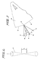
- FIGURE 3 The rastering effect accomplished by the rotating raster disc 26 can be best appreciated from FIGURE 3.
- Two reflecting surfaces 36′, 36 ⁇ (which are identical to the reflecting surfaces 36 of FIGURE 1, the ′ and ⁇ superscripts merely being used for convenience of reference) meet at an edge 40 which is generally parallel to the axis of rotation of the raster disc 26.
- Each of the reflecting surfaces 36′, 36 ⁇ subtends an angle, ⁇ , about the axis of the raster disk 28 which is equal, in degrees of arc, to 360 divided by the total number of reflecting surfaces 36.
- An incident light ray 42 from the continuous wave carbon dioxide laser 20 strikes the reflecting surface 36′ (FIGURE 3) with an angle of incidence, i , measured from the normal 44 to the reflecting surface 36′.
- the normal 44 to the reflecting surface 36′ moves to the position illustrated in FIGURE 3 (for purposes of this discussion it is assumed that the raster disk 28 moves in the clockwise direction; however, the direction of rotation is not a limitation).
- the incident light ray 42 strikes the reflecting surface 36 ⁇ with an angle of incidence, i* , measured relative to the normal 48 to the reflecting surface 36 ⁇ .
- the length of the skin removal zone 14 can be adjusted by vertically adjusting the position of the raster disk 28.
- Classical trigonometric relationships determine the effect of vertical adjustment on the length of the skin removal zone 14. If desired, the length ofthe skin removal zone 14 can thus be adjusted so that the entire surface of a edible material is deskinned in a single pass. Alternatively, the length of the skin removal zone 14 can be adjusted so that essentially parallel strips of skin are removed from the edible material at the skin removal zone 14.
- a second focusing lens 25 between the raster disk and the conveyor means 10.
- the second focusing lens helps to further concentrate the laser light beam after it has been reflected from the peripheral edge of the raster disk.
- the distance of the focusing lens 24 from the point of reflection on the peripheral surface of the raster disk 28 and the distance of the second lens 25, if used, will determine the elevation of the depth of field of the laser light beam 22 focus relative to the upper surface of the conveyor means 10.
- adjustment of the focusing lenses 24, 25 along the axis of the laser light beam can readily be effected to accommodate the location of the surface to be skinned.
- a gaseous cloud forms in the vicinity of the skin removal zone 14. That gaseous cloud may interfere with the action of the continuous wave carbon dioxide laser 20 if the cloud is not removed.
- the gaseous cloud may be removed by causing an air current to traverse the skin removal zone 14.
- a collection tube 52 may be positioned next to the conveyor means 10 in general lateral alignment with the skin removal zone 14.
- the collection tube 52 may be centered so as to be in general alignment with the center of the depth of focus of the laser light beam.
- a suitable conventional suction pump or fan 54 may be connected to the collection tube 52. Accordingly, when the suction pump 54 is operating, it sucks air into the collection tube 52.
- the pump 54 is sized to entrain a sufficiently large volumetric air flow so that the gaseous cloud is sucked into the collection tube 52 with sufficient speed that the gaseous cloud does not interfere with operation of the laser light beam.
- the length of the skin removal zone 14 in the direction transverse to the direction of movement of the conveyor means 10 may be larger than the maximum width of the edible material being deskinned. In that event, one side of the edible material would be deskinned during a single pass through the skin removal zone.
- the apparatus described above will remove a strip of skin from the edible material.
- the edible material may be passed through the skin removal zone 14 one or more additional times, with the material being positioned on the upper surface of the conveyor means on the successive passes so that a part of the material which was not previously deskinned is in longitudinal alignment with the skin removal zone 14.
- additional skin removal zones could be provided.
- the additional skin removal zones would preferably be placed so that the strips of skin which are removed thereby are contiguous with or slightly overlapping with the strip of skin removed by the first skin removal zone 14.
- the edible material can be turned over and passed through the skin removal zone 14.
- the laser energy to remove the skin from the edible material 66 may be provided by three lasers 70, 70′, 70 ⁇ . These laser energy sources are comparable to that described above in connnection with the first embodiment. Each laser generates a beam of laser energy which is directed toward the edible material 68.
- suitable conventional reflecting mirrors 72, 72 ⁇ may be provided for corresponding laser energy sources 70, 70 ⁇ so that three laser beams impinge upon the surface of the edible material 68 at angles of about 120°.
- Each laser beam also impinges upon a suitable conventional laser energy absorber 74, 74′, 74 ⁇ after the edible material 68 passes the beams. With this arrangement, there is little likelihood that spurious laser energy will escape into the environment.
- the multiple beams could also be obtained by beam splitting or, as illustrated, by providing a multiplicity of laser energy sources. In either event, it would be possible to remove skin completely around the girth of a edible material in a single pass.
- an empirically obtained chart of skin removal efficiency for variations in carbon dioxide laser power density will be needed for (a) the species of edible materials to be skinned and (b) for edible materials with different states of preparation, i.e., fresh, frozen, thawed, or cooked.
- the skin removal efficiency may be presented as a surface removal rate per kilowatt of laser power, i.e., cm2/sec/kw.
- the power density, P D is expressed as kilowatts per unit cross-sectional area of the focused laser beam, kw/cm2.
- a sample empirical chart of skin removal efficiency for laser power density is provided in FIGURE 4 for cooked tuna 60 and frozen tuna 62.
- the highest available skin removal efficiency may, however, be limited by the maximum power available from the continuous wave carbon dioxide laser being used. From the empirical chart, the highest skin removal efficiency will be identified. For example, for frozen tuna fish carcasses, a maximum skin removal efficiency of about 11 cm2/sec/kw is available for a laser power density of about 67 to 93 kw/cm2.
- the power density discussed above represents the spot power density, i.e., the power density of the focused beam at the location of the focus.
- a time-average power density for a rastered laser beam is determined from the available output power of the laser and the cross-sectional area of a traversal stroke of the rastered beam. That cross-sectional area corresponds to the product of the length of the traversal stroke times the diameter of the focused beam.
- the cross-sectional area of the laser beam is known so the the time-averaged power requirement will be established.
- the relationship between the spot power density and the time-averaged power density depends upon the angular velocity of the raster disk, the number of reflecting surfaces on the peripheral surface of the raster disk, and the laser beam concentration accomplished by focusing. As those factors are known for a given apparatus, the relationship between power for the continuous wave carbon dioxide laser and the time-averaged power density can easily be determined.
- the skin removal results have been correlated on the spot power density since the intensity of the laser energy as measured by the spot power density is sufficient to effect skin removal. Whether the time-averaged power density and the spot power density are equally determinative parameters in predicting-skin removal efficiency has not been completely resolved. Knowing the spot power density available from the laser, the corresponding skin removal efficiency can be ascertained from correlations of empirical data.
- the empirical data correlations indicate that there is, in general, a maximum skin removal efficiency.
- the laser is operated at a power level which produces the spot power density corresponding to the maximum skin removal efficiency for the product being skinned.
- the spot power density required for maximum skin removal efficiency is greater than the spot power density available from the particular laser and optical system being used, then the maximum available spot power density from the laser and its optical system is used, with the skin removal efficiency being ascertained from the empirical data.
- the required laser power is determined.
- the surface removal rate, in cm2/sec can be determined from the laser power and the skin removal efficiency. Knowing the length of the skin removal zone 14, the velocity of the edible material, in cm/sec, is therefore known which will meet the requirements of spot power density and skin removal efficiency.
- the speed of the conveyor means 10 in the first predetermined direction is known and appropriate speed adjustments to the drive motor(s) for the conveyor means 10 are made.
- the edible materials to be deskinned are also examined to determine the maximum and minimum height of the material surface above the upper surface 14 of the conveyor means 10. Then, the elevation of the raster means 26 above the upper surface 14 is adjusted so that the length of the skin removal zone corresponds to the width used in determination of the effective cross-sectional area of the laser beam. In addition, the position of the focusing lens 24 is adjusted so that the area of the edible material to be deskinned lies within the depth of field of the focus of the laser beam.
- the suction pump 54 is started to establish a current of air across the skin removal zone 14, the motor 34 is started to rotate the raster disk 28, and the continuous wave carbon dioxide laser 20 is energized at the power level determined to be appropriate from the analysis discussed above.
- edible materials are placed on the upper surface 16 of the conveyor means 10 to be advanced into the skin removal zone 14. As the edible material moves through the skin removal zone 14, the skin is ablatively removed by the action of the laser light beam.
- the fish skin As the fish skin is ablatively removed by the laser, it is vaporized into a plume of smoke which is substantially free of ash and soot.
- the smoke plume is sucked away into the collection tube 52 and ultimately disposed of.
- the byproducts of the ablative process include water, carbon dioxide, and carbon. It is possible that burning protein molecules in the fish skin during the ablative process will result in noxious fumes. Accordingly, the collected smoke plume may be further treated to eliminate such noxious wastes.
- the laser light beam rapidly traverses the surface of the edible material.
- the laser light beam vaporizes a strip of skin having a length corresponding to the length of the skin removal zone measured transversely to the direction of movement of the conveyor means 10 and having a width corresponding to the focused diameter of the laser light beam. Since the velocity of movement of the conveyor surface is coordinated as discussed above, each successive traversal of the edible material by the laser light beam at least slightly overlaps the preceding traversal of the edible material. As a result, the successive traversals give the appearance of a continuous skin removal.
- the carbon dioxide laser is preferred for use in connection with this method since fish flesh as well as other edible materials have a substantial amount of water, since water has a strong absorbency for the wavelength of the carbon dioxide laser beam, and since there is usually a substantial color difference between skin and the underlying flesh.
- the foregoing factors give rise to a shift in the efficiency of removal between skin and flesh which leads to a natural mechanism to stop the laser ablation process.
- the skin is vaporized virtually instantaneously into a gaseous cloud. That gaseous cloud is removed from the skin removal zone 14 by the current of air caused to traverse the skin removal zone with a sufficient velocity to clear the gaseous cloud. If necessary, the gaseous products of the skin removal are treated to remove noxious and/or toxic constituents.
- the edible material may be turned over and passed through the skin removal zone a second time to remove the skin from the second side of the carcass.
- Such a procedure is used where the traversal width of the laser beam in the skin removal zone equals or exceeds the width of the edible material as it lies on the upper surface 16 of the conveyor means 10.
- the edible material can be passed through the skin removal zone one or more additional times. During each successive pass, the edible material is placed such that an unskinned part of the material is in longitudinal alignment with the skin removal zone 14. Accordingly, the skin is removed in generally parallel strips from the edible material.
- additional skin removal zones can be provided, typically such additional skin removal zones are laterally offset from the first skin removal zone so that there is at least a slight overlap between adjacent zones when viewed from the direction of movement of the conveyor means 10.
- the process of the present invention has many significant advantages when contrasted with existing fish skin removal processes.
- the skin is vaporized from the edible material in an essentially instantaneous process. That vaporization eliminates the need to dispose of malodorous solid waste in the form of fish skin and associated residue. Instead, a gaseous plume results that can be effectively treated as required to remove any impurities which may exist. Neither soot nor ash results from the process.
- the rate of energy input per unit area is so high that the surface layer can be vaporized while thermal conduction to the underlying flesh or tissue is insignificant. This advantage is not possible from other techniques, including for example flame peeling or steam peeling of potatoes.
- the laser rastering technique removes the skin from depressions or protrusions with equal efficacy. Moreover, since the ablative process of skin removal is essentially self-limiting due to the high water content of the underlying flesh or tissue, the presence of depressions or protrusions does not cause any change in the amount of material removed from the material surface.
- Another advantage of the present method of skin removal deals with the effect of skin removal on the underlying flesh or tissue.
- the underlying flesh or tissue is not removed in any greater thickness in the vicinity of depressions or protrusions on the surface.
- the rapidity of the process does not cause significant amounts of residual heat in the underlying flesh or tissue. Accordingly, partial cooking of the underlying flesh or tissue is avoided.
- the method can be used on raw, as well as cooked, thawed or frozen edible materials.
- the process of the present invention allows a substantial reduction in the amount of hand labor required in removal of the thin, naturally-occurring outer protective layer from edible materials such as is used in tuna processing industry, the potato processing industry, the tomato processing industry, and the like. More specifically, instead of having each item skinned or peeled by hand, the only hand labor required is to place the edible materials on the conveyor means. Presently, it is estimated that the new method will permit reductions of as much as 80% in labor costs for tuna skinning. For potatoes, peel loss can be reduced to 2 to 3 percent of the starting weight as compared to a loss of 6 to 25 percent which is common with other peeling processes.
Landscapes
- Life Sciences & Earth Sciences (AREA)
- Engineering & Computer Science (AREA)
- Food Science & Technology (AREA)
- Wood Science & Technology (AREA)
- Zoology (AREA)
- Chemical & Material Sciences (AREA)
- Polymers & Plastics (AREA)
- Laser Beam Processing (AREA)
Description
- This invention relates generally to removal of the naturally occurring outer protective layer from food, vegetables, fruits, and other edible material. More particularly, the invention concerns a process wherein a suitably powered continuous wave, carbon dioxide laser beam is used to vaporize the surface layer or layers from food, fruits, vegetable matter or edible material.
- There are a large number of situations in the food processing industry where one step in the process involves removing the thin, naturally-occurring outer protective layer from a large number of items. Typically, the one step is part of a more involved process. Such a process might be canning, for example, by which the food is preserved for transportation and marketing in preserved form. Another process might involve subsequent slicing, or cooking, or the like.
- There are, of course, a large number of particular foodstuffs for which the present process of removing the thin, naturally-occurring outer protective layer is applicable. Some typical examples will now be discussed in greater detail.
- The fish processing industry has grown at very rapid rates in recent years due to increased consumer demand resulting from changing dietary habits, increased costs of other staple foods and improved methods of packing and preserving foods. The fishing industry has thus long since passed from a regional industry to a worldwide industry where fishing vessels travel long distances from their home ports to locations where prime fishing grounds are located. The foregoing, coupled with the competitive nature of the industry and other factors necessitate more than ever, the adoption of economical automated processing and handling methods. That is particularly true of one specific fishing industry, the tuna fishing industry.
- The tuna fish is the largest volume product processed by the fish packing industry. The tuna industry is highly competitive and certain operations are extensively automated. The skinning problem, i.e., removal of the naturally occurring, thin, outer protective layer from the fish, is a significant factor in the way the tuna industry processes and packs tuna. According to the typical practice, freshly caught tuna is promptly frozen (sometimes in brine) while still on board the fishing vessels. The frozen tuna is delivered to storage facilities or directly to the processors while still in the frozen state.
- When required for production, frozen tuna are removed from storage, approximately graded by size, and thawed. After thawing, the fish are typically placed on conveyor belts, gutted, washed by hand, placed on cooking racks, and cooked in steam ovens. When cooked, the fish are cooled for manual handling.
- When cooled, the heads and tails are removed, and the bodies are placed on conveyor belts. The cooked skin has deteriorated into a tar-like substance and is scraped away from the edible loins with hand-held knives or scrapers. The loins are pulled from the bones by hand and the undesirable blood meat is also scraped off. In the scraping process, some edible meat is lost with the skin as well as with the blood meat.
- Next, the loins are placed on conveyor belts and sent to can filling machines. Each can is automatically packed with tuna, water or oil, and seasoning. Finally, each can is sealed and sterilized by a "retort" cook.
- As can be seen from the foregoing description of the tuna packing process, onecritical step in the overall process is the highly labor-intensive operation of removing the skin from the fish loins. Considerable effort is exerted to keep the fish skin moist and elastic to ease its removal by manually scraping with a knife. Even so, the texture changes with time over the 10 or 15 minutes (or longer) the operator takes to clean a number of fish brought to the cleaning table by trolley.
- Skin removal has been particularly problematic when dealing with tuna fish. It has been found that raw tuna, whether fresh or frozen, cannot be successfully skinned without simultaneously removing hunks of the underlying tuna meat along with the skin. Since the underlying tuna meat is the commercially significant part of the tuna fish, waste of that meat in a skinning process is commercially unacceptable.
- The prevalent method of tuna skinning thus involves deferring the skinning process until after the tuna fish has been cooked. It has been found that during the cooking process a gelatinous layer forms between the skin and the underlying tuna meat or flesh. As a result, the skin will slide off the underlying tuna meat with the gelatinous layer acting much like a lubricant. Actual removal of the skin, however, continues to be a hand operation.
- Automated skin removal processes have been proposed such as (a) skinning fish with a caustic solution that is applied to the skin of the fish to saponify the fat thereon and cause a partial dissolution of the skin, (b) selective melting or softening of the skin only on the surface of the frozen fish, (c) contacting the skin of the fish with an acid to produce a denaturization of the fish followed by jets of water to remove the skin, and (d) application of an aqueous dispersion of an at least partially hydrolyzed starch to the skin of the fish followed by drying the skin to cause it to partially peel and thereafter removing the skin. None of the foregoing processes have been particularly successful so that the industry still resorts to manual removal or scraping to remove the fish skin.
- Mechanical methods have been proposed to scrape or brush the skin from the cooked fish. But those mechanical methods have their own set of problems, principally that scraping too vigorously can remove valuable edible meat while scraping too gently does not remove all the skin. Secondly, because the fish surface is not always smooth, i.e., there may be indentations or depressions, dependent on the history of fish handling, which inhibit skin removal with mechanical processes. Thus, the skin will not be removed from these parts mechanically and will still require manual removal. Finally, the sticky, greasy nature of the oily fish skin waste quickly contaminates scraper blades or brushes of mechanical devices and, if not removed, impairs the effectiveness of the cleaning operation.
- Still further, the voluminous resultant waste from the skinning process presents a substantial disposal problem for the tuna packing industry. The waste is malodorous and difficult to handle.
- Accordingly it is seen that the need continues to exist for a fish skinning process which overcomes problems of the type discussed above.
- Another commercial process which involves removal of the thin, naturally-occurring, outer protective layer from an edible item is the preparation of potatoes. After raw potatoes are washed to remove remaining soil in which they are grown, they are frequently skinned as a preparation for other processes. For example, when potatoes are prepared for use as French fries, julienne strips, potato chips and the like, the preparatory step of skinning is typically performed.
- In commercial potato treatment facilities, potato skin removal is accomplished automatically rather than manually. That automation is essential due to the large volume of potatoes which must be handled in any given growing season. A typical potato has numerous indentations and irregularities which depart from a smooth surface. Those irregularities and indentations impede the efficient removal of skin. Thus, it is not unsurprising that considerable potato material beneath the skin is lost in commercial potato skinning processes.
- Commercially, potato skinning is done with a variety of processes. One common process abrades the skin continually removing the high spots until skin in the low spots has been removed. Another process involves the use of lye to effect peeling of the potatoes. Other processes that have been tried are flame peeling and steam peeling, both of which use heat which is conducted into the layers of potato tissue underlying the skin. While steam peeling is used commercially, flame peeling was tried but was then discarded. Each of these various techniques causes damage to the underlying tissue. That damage results in loss of yield in the finished potato product.
- Experience with commercial potato skinning processes indicates'that the yield loss ranges from 6 to 25% of the potato during skinning or peeling. On a commercial scale, potato material losses of that level represent serious revenue losses as well.
- Accordingly, it is seen that a need continues to exist for processes which would reduce that yield loss.
- Another commercial process in which the thin, naturally-occurring outer protective layer is removed from a high volume of items is tomato processing. For example, in the preparation of tomato catsup, tomato paste, tomato puree, and canned tomatoes, the raw vegetable is skinned as one step in processing.
- Tomato skin removal is rather difficult to accomplish. And, when the skin is removed, the underlying tomato pulp tends to be removed with the skin in an irregular and unpredictable manner. Accordingly, material losses like those discussed above in connection with potatoes are also experienced with tomatoes.
- As is well known, beneath the skin of the tomato is a pulpy portion which surrounds a central region having seeds. The central portion tends to have a higher liquid content than does the pulpy portion. Because of this characteristic of the tomato, when products such as tomato catsup and tomato paste are made on a commercial scale, loss of parts of the pulpy portion along with the skin has processing ramifications since the central portion of the tomato generates a higher water content which has to be reduced to obtain the desired consistency in the end product.
- Accordingly, it is seen that with tomatoes, there is a further advantage to be obtained from a process which reduces the amount of pulpy flesh removed with the skin.
- In more general mechanical processes, scraping of one material from the surface of another has been effected in various ways. One recent method involves the use of a continuous wave, carbon dioxide laser light beam which is reflected from a multifaceted circumferential surface of a rotating disk as the light beam is focused on the surface of the object to be scraped. The multifaceted circumferential surface of the disk, combined with rotation of that disk, causes the focused laser light beam to oscillate from side to side so that the light beam appears to have a significant width. When a painted metal surface traverses that light beam, the paint is removed from the surface without adversely affecting the underlying metal. Such a laser device was not considered to be suitable for use on foodstuffs since, in foodstuffs, the composition varies as a continuum unlike the situation where one material, such as paint, is removed from a second, dissimilar material, such as metal.
- It is also known, for example, to use a laser beam to cut a hard nut shell into two portions that can be removed to expose the internal nut meat. Such a system is disclosed in U.S. Patent No. 4,358,467 issued to Patel on November 9, 1982.
- In accord with the present invention, a process of removing a thin naturally-occuring outer protective layer such as a skin from a vegetable, fruit, fish, or other edible material using a focused continuous wave laser beam, in which the edible material is moved through a skin removal zone in a first direction at a first predetermined speed, to ablatively remove the outer protective layer from the edible material, is characterised in that the surface of the outer protective layer facing the laser source is exposed to the continuous wave laser beam as the edible material is bodily moved through said skin removal zone.
- The ablative skin removal involves exposing the edible material to a focused continuous wave laser beam while the edible material moves through the skin removal zone. The focused laser beam is rapidly traversed across the edible material in the skin removal zone. The direction of movement of the laser beam is generally perpendicular to the first direction. Moreover, the laser beam is traversed at a second predetermined speed which is related to the first predetermined speed such that the edible material advances by a distance no greater than the width of the focused laser beam during each traversal of the beam. An air current is caused to flow across the skin removal zone to remove the plume of smoke and gaseous products from vaporization of the skin from that zone. The laser beam is focused so that the depth of focus is positioned to include the range of heights from which skin is to be removed from the edible material.
- If desired, the lateral limits of laser beam traversal may be selected so as to be at least equal to the maximum width of a edible material so that one entire side of the edible material can be deskinned on a single pass. Alternatively, it may be more energy efficient to select the lateral limits of laser beam traversal to a smaller value, for example one inch. In this event, the edible material may require several passes through the skin removal zone to remove generally parallel strips of skin. In either event, the edible material can simply be turned over to remove skin from the other side.
- Multiple passes of the edible material through the skin removal zone can also be reduced, or eliminated entirely, by providing two or more skin removal zones, each with a traversing laser beam, and positioning the skin removal zones so that they slightly overlap one another when viewed in the direction of edible material movement.
- The skin removal process of this invention can be used regardless of whether the edible material is fresh, frozen, thawed, or cooked. The power density of the laser beam will, however, be adjusted to account for whether the edible material is fresh, frozen, thawed, or cooked.
- Preferably, a continuous wave carbon dioxide laser is used as the source of the laser light beam. The continuous wave character is desirable since the laser beam is thus not intermittent. A carbon dioxide laser is also preferred since the wavelength of coherent light in the laser beam is one which is absorbed by water. As water is a significant component of foodstuffs, the carbon dioxide laser beam thus interacts with the product being skinned in a self-limiting manner. Moreover, the carbon dioxide laser happens to be the most economical laser in terms of capital cost per kilowatt.
-
- Many objects and advantages of the present invention will be apparent to those skilled in the art when this specification is read in conjunction with the drawings wherein like reference numerals are applied to like elements and wherein:
- FIGURE 1 is a schematic illustration of a deskinning apparatus which is suitable for practicing the present invention;
- FIGURE 2 is an enlarged illustration of the manner in which a laser beam focuses;
- FIGURE 3 is an enlarged scale detail view of part of the raster wheel of the apparatus of FIGURE 1;
- FIGURE 4 is a chart showing representative skin removal efficiency for different laser power densities and for different type of edible materials;
- FIGURE 5 is an illustration of another embodiment in which skin is removed simultaneously from the entire girth of an edible material; and
- FIGURE 6 is a view taken along the line 6-6 of FIGURE 5, in reduced scale.
- The present invention involves use of a high intensity energy deposit system, such as a focused laser light beam, to ablatively remove skin from an edible material such as a fish carcass, a potato, a tomato, fruit, vegetables, and the like. The focused laser light beam literally vaporizes the skin from the edible material without heating the flesh underlying the skin. For convenience, the process will be described generally in connection with removal of skin from fish carcasses.
- While it is expected that the method of the present invention can be practiced with various apparatus, one suitable type of apparatus will now be described which can be used to practice the invention. A suitable conventional conveyor means 10 (FIGURE 1) provides a support surface for one or more edible materials. The conveyor means 10 is also operative to move edible materials in a first predetermined direction, illustrated by the arrow labelled 12, toward and through a skin removal zone 14, illustrated for convenience by a double-headed arrow.
- The conveyor means 10 has an
upper surface 16 which can be fabricated from, or coated with, any suitable conventional material which can be readily cleaned and which is otherwise suitable for use with the foodstuff being skinned, tuna fish in the present case. - As an energy source, a continuous wave
carbon dioxide laser 20 with the ability to generate alaser light beam 22 which can be focused to a high power density, PD, is preferred, where power density represents the output energy of the laser divided by the cross-sectional area of the focused beam. For example, with a 2.5 kw carbon dioxide laser beam, a power density of 79.6 kw/cm² at a wavelength of 10,600nm is obtained when focused to a spot diameter of 0.2 cm. - A continuous wave laser is preferred, rather than an intermittent laser, since the
laser light beam 22 is oscillated through the skin removal zone 14. With an intermittent laser light source, alternating periods of energy pulses introduce an additional level of complexity since the apparatus needs to be synchronized with the energy pulses to assure that each laser energy pulse overlaps the footprint of the immediately preceding laser energy pulse on the skin surface being removed. Such a condition is not a requirement for continuous wave lasers. Accordingly, it appears that this additional operational requirement for a continuous wave laser has considerable probability of accelerating the speed with which the conveyor means 10 can advance edible materials through the skin removal zone 14. - The carbon dioxide laser is presently preferred as the laser energy source. The wavelength of the
laser light beam 22 generated by a continuous wavecarbon dioxide laser 20 is a wavelength of light for which water has a strong absorption. As the apparatus will be used to remove skin from edible materials, and since flesh beneath the skin has a substantial water content, the ablative action of thelaser light beam 22 on the skin is self-limited by the edible material due to absorbency of water to the wavelength of thelaser light beam 22. - Of the currently available lasers, the carbon dioxide laser also happens to be the most economical in terms of capital cost per kilowatt of power. While the carbon dioxide laser is presently preferred, other lasers may be desirable for other reasons. Moreover, new types of lasers may be developed which are even more attractive for the purposes herein described.
- Power density requirements for deskinning fish with the continuous wave
carbon dioxide laser 20 are presently estimated at about 90 kw/cm² and higher if and when those power densities become available. Required power density is also dependent upon the species of fish carcasses being deskinned and upon such factors as whether the carcass is cooked, fresh, frozen, or thawed. Empirically obtained variations of (a) the surface removal rate (i.e., cm²/sec) per kilowatt of laser energy for (b) various power densities of thelaser light beam 22 measured in kilowatts per square centimeter for the particular fish carcass establish the preferred power density for a particular carcass deskinning application. The following tables provide a comparison of power density, as well as other information, for one species of tuna fish with different conditions of preparation (Table 1), and for different edible material (Table 2).TABLE 1 REMOVAL EFFICIENCY AS A FUNCTION OF POWER DENSITY FOR FROZEN, THAWED, AND COOKED SKIPJACK TUNA Condition Beam Power, kw Power Density, kw/cm² Transit Speed, cm/sec Removal, cm²/sec Removal Eff., cm²/sec /kw Frozen 2.92 93.0 18.0 32.4 11.1 2.11 67.2 13.0 23.4 11.1 1.36 43.3 5.0 9.0 6.6 Thawed 2.90 92.4 25.4 45.7 15.8 Cooked 2.63 83.8 42.3 76.1 28.9 1.00 31.8 5.5 9.9 9.9 TABLE 2 REMOVAL EFFICIENCY AS A FUNCTION OF POWER DENSITY FOR POTATOES AND TOMATOES Item Beam Power, kw Power Density, kw/cm² Transit Speed, cm/sec Removal, cm²/sec Removal Eff., cm²/sec /kw Potatoes 2.80 89.2 33.7 60.7 21.7 2.00 63.7 24.1 43.4 21.7 1.44 45.9 14.4 25.9 18.0 Tomatoes 0.62 19.75 24.0 43.2 69.7 0.30 9.55 5.5 9.9 33.0 - In Tables 1 and 2, the focused spot diameter of the continuous wave carbon dioxide laser is 0.2cm and the beam scan length is 1.8 cm.
- The
laser light beam 22 from the continuous wavecarbon dioxide laser 20 passes through a focusinglens 24 which has a focal length corresponding essentially to the total linear distance traversed by thelaser light beam 22 between the focusinglens 24 and theupper surface 16 of the conveyor means 10. A suitable lens may have a focal length in the range of 18 to 24 inches. - The precise distance from the
upper surface 16 of the conveyor means 10 to the focusinglens 24 measured along the length of thelaser light beam 22 depends upon (a) the upper and lower elevations of the skin surface to be removed measured relative to theupper surface 16 of the conveyor means 10, (b) the depth of field at the focus of thelaser light beam 22, and (c) the focal length of the focusinglens 24. In particular, the depth of field at the focus of thelaser light beam 22 is positioned so as to encompass both the upper and lower elevations of the skin surface to be removed. And, the focal length measured from the middle of the depth of field at the focus of thelaser light beam 22 positions the focusinglens 24. - Generally speaking, the depth of field at the focus, Df, (see FIGURE 2) for any lens is a function of the diameter of the lens, the wavelength of the light beam being focused, the focal length of the lens, and the quality of the light beam (i.e., the amount of divergence over a given distance, typically measured as stearadians/meter). Depth of field at the focus for a lens can be expressed as:

- Since the focusing lens 24 (FIGURE 1) shapes the
laser light beam 22 toward a small diameter focal spot, it is desirable to rapidly move that focal spot laterally tothe direction ofmovement 12 of the conveyor means 10 so that thelaser light beam 22 virtually corresponds to a line in the skin removal zone 14 that is generally perpendicular to the direction ofmovement 12. Further, if the rapid traversal of the focal spot is accomplished such that the conveyor means 10 advances in the direction ofmovement 12 by a distance no greater than the diameter of the focal spot, then thelaser light beam 22 has the virtual effect of being a wide blade. - To accomplish the rapid traversal of the focal spot, the
laser light beam 22 is reflected from a raster means 26 to the skin removal zone 14. The raster means 26 includes araster disc 28 having a circumferentialperipheral surface 30. Theraster disk 28 may have a diameter on the order of 14 inches and is suitably mounted on arotatable shaft 32. Suitable conventional bearings (not shown) may be used to mount the shaft to supporting structure (not shown) so that theraster disc 28 is positioned above theupper surface 16 of the conveyor means 10. Ordinarily, the axis of theshaft 32 will be in general alignment with the direction ofmovement 12 of the conveyor means 10 so that the focal spot can traverse theupper surface 16 of the conveyor means 10 in a direction generally perpendicular to the direction ofmovement 12. - A suitable
conventional motor 34 is attached to one end of therotatable shaft 32 and is operable to spin the shaft and theraster disc 28 at angular velocities on the order of 200 to 2000 rpm. Theperipheral surface 30 of theraster disc 28 has an integral number of generally planar reflecting surfaces 36. While only sixteen reflectingsurfaces 36 are illustrated in FIGURE 1 for the sake of clarity, thirty-six or more identical reflecting surfaces can be provided on theperipheral surface 30. These reflecting surfaces 36 may, for example, be fabricated from a polished metal such as copper. - The rastering effect accomplished by the
rotating raster disc 26 can be best appreciated from FIGURE 3. Two reflectingsurfaces 36′, 36˝ (which are identical to the reflectingsurfaces 36 of FIGURE 1, the ′ and ˝ superscripts merely being used for convenience of reference) meet at anedge 40 which is generally parallel to the axis of rotation of theraster disc 26. Each of the reflectingsurfaces 36′, 36˝, subtends an angle, õ, about the axis of theraster disk 28 which is equal, in degrees of arc, to 360 divided by the total number of reflecting surfaces 36. - An incident
light ray 42 from the continuous wave carbon dioxide laser 20 (FIGURE 1) strikes the reflectingsurface 36′ (FIGURE 3) with an angle of incidence, i, measured from the normal 44 to the reflectingsurface 36′. As theraster disk 28 moves so that theedge 40 comes into alignment with the incidentlight ray 42, the normal 44 to the reflectingsurface 36′ moves to the position illustrated in FIGURE 3 (for purposes of this discussion it is assumed that theraster disk 28 moves in the clockwise direction; however, the direction of rotation is not a limitation). As theraster disk 28 rotates past theedge 40, the incidentlight ray 42 strikes the reflectingsurface 36˝ with an angle of incidence, i*, measured relative to the normal 48 to the reflectingsurface 36˝. - It can be shown from elementary plane geometry that the angle between the normal 44 to the reflecting
surface 36, and the normal 48 to the reflectingsurface 36˝ is equal to the angle, õ. From elementary physics it is known that the angle of reflection from a surface is equal to the angle of incidence. Thus, as theraster disk 28 rotates across eachedge 40, the reflected light ray moves from thedirection 46 having an angle of reflection, r, measured with respect to the first surface normal 44 to thedirection 50 having an angle of reflection, r*, measured with respect to the second surface normal 48. It can be shown from elementary plane geometry and from elementary physics that the reflected light ray changes its direction by an angle equal to 2õ. - Moreover, it will be observed from the foregoing discussion that the angular change in the reflected light ray is instantaneous in comparison to the rate at which the second surface normal 48 moves to the
position 46 as theraster disk 28 rotates. It will be seen from FIGURE 1 and the foregoing discussion that the focusedlaser light beam 22 traverses an angle of 2õ centered on the surface of theraster disk 28. As a result, the length of the skin removal zone 14 can be adjusted by vertically adjusting the position of theraster disk 28. Classical trigonometric relationships determine the effect of vertical adjustment on the length of the skin removal zone 14. If desired, the length ofthe skin removal zone 14 can thus be adjusted so that the entire surface of a edible material is deskinned in a single pass. Alternatively, the length of the skin removal zone 14 can be adjusted so that essentially parallel strips of skin are removed from the edible material at the skin removal zone 14. - If desired, it is also possible to place a second focusing
lens 25 between the raster disk and the conveyor means 10. The second focusing lens helps to further concentrate the laser light beam after it has been reflected from the peripheral edge of the raster disk. - It will be seen from FIGURE 1 that the distance of the focusing
lens 24 from the point of reflection on the peripheral surface of theraster disk 28 and the distance of thesecond lens 25, if used, will determine the elevation of the depth of field of thelaser light beam 22 focus relative to the upper surface of the conveyor means 10. Thus, adjustment of the focusinglenses - When skin from the edible material is ablatively removed, a gaseous cloud forms in the vicinity of the skin removal zone 14. That gaseous cloud may interfere with the action of the continuous wave
carbon dioxide laser 20 if the cloud is not removed. The gaseous cloud may be removed by causing an air current to traverse the skin removal zone 14. To this end, acollection tube 52 may be positioned next to the conveyor means 10 in general lateral alignment with the skin removal zone 14. In addition, thecollection tube 52 may be centered so as to be in general alignment with the center of the depth of focus of the laser light beam. A suitable conventional suction pump orfan 54 may be connected to thecollection tube 52. Accordingly, when thesuction pump 54 is operating, it sucks air into thecollection tube 52. Thepump 54 is sized to entrain a sufficiently large volumetric air flow so that the gaseous cloud is sucked into thecollection tube 52 with sufficient speed that the gaseous cloud does not interfere with operation of the laser light beam. - There are, of course, certain modifications of the apparatus which can be made. For example, it is possible to use optics to reshape the laser light beam from a cylindrical shape to a generally planar shape using a cylindrical lens or a two-dimensional parabolic mirror to focus the laser light beam in one direction. Such an optical system would likely be used in lieu of one or both of the focusing
lens raster disk 26. - While the apparatus has been described with a collection means that uses a suction pump, it will also be appreciated that a pressure pump or fan could be employed creating a jet of air to substantially continuously sweep the skin removal zone 14. For that matter, it would even be possible to use both a pump or fan to create a jet and a suction collection arrangement to capture the jet thus created.
- Should it be determined that the gaseous products of the ablative skin removal process are toxic or noxious, it is also contemplated that the exhaust from the suction pump or
fan 54 would be further processed to remove the noxious or toxic components. - From the foregoing description of possible apparatus, it will be noted that the length of the skin removal zone 14 in the direction transverse to the direction of movement of the conveyor means 10 may be larger than the maximum width of the edible material being deskinned. In that event, one side of the edible material would be deskinned during a single pass through the skin removal zone.
- On the other hand, if the maximum width of the edible material being deskinned exceeds the length of the skin removal zone 14, then the apparatus described above will remove a strip of skin from the edible material. To remove remaining skin from the edible material, the edible material may be passed through the skin removal zone 14 one or more additional times, with the material being positioned on the upper surface of the conveyor means on the successive passes so that a part of the material which was not previously deskinned is in longitudinal alignment with the skin removal zone 14.
- Alternatively, additional skin removal zones could be provided. In this event, the additional skin removal zones would preferably be placed so that the strips of skin which are removed thereby are contiguous with or slightly overlapping with the strip of skin removed by the first skin removal zone 14.
- In order to remove skin from the second side of the edible material, the edible material can be turned over and passed through the skin removal zone 14.
- While the foregoing description of apparatus has assumed for simplicity that the edible materials move horizontally, it is also possible that the edible material could move vertically through a skin removal zone. In this event, it could be possible to remove skin completely around the girth of a edible material in a single pass through the apparatus.
- It is also possible to arrange a pair of generally
horizontal conveyors 60, 62 (see FIGURE 5) with anarrow space 64 between them in which two or more laser beams are simultaneously focused on different sides of the article being skinned. In this embodiment, it may also be possible to provide anannular manifold 66 in the space between the horizontal conveyors to direct a jet of compressed air toward theedible material 68 so as to carry off the gaseous products from the effect of the laser on the skin. - As can best be seen from FIGURE 6, the laser energy to remove the skin from the
edible material 66 may be provided by threelasers edible material 68. When the lasers are all disposed in generally parallel relation as in FIGURE 6, suitable conventional reflectingmirrors laser energy sources edible material 68 at angles of about 120°. Each laser beam also impinges upon a suitable conventionallaser energy absorber edible material 68 passes the beams. With this arrangement, there is little likelihood that spurious laser energy will escape into the environment. - The multiple beams could also be obtained by beam splitting or, as illustrated, by providing a multiplicity of laser energy sources. In either event, it would be possible to remove skin completely around the girth of a edible material in a single pass.
- Having thus described apparatus which is suitable for the deskinning process of the present invention, the edible material deskinning process will now be described in conjunction with that apparatus.
- As a preliminary matter, an empirically obtained chart of skin removal efficiency for variations in carbon dioxide laser power density will be needed for (a) the species of edible materials to be skinned and (b) for edible materials with different states of preparation, i.e., fresh, frozen, thawed, or cooked. The skin removal efficiency may be presented as a surface removal rate per kilowatt of laser power, i.e., cm²/sec/kw. The power density, PD, is expressed as kilowatts per unit cross-sectional area of the focused laser beam, kw/cm². A sample empirical chart of skin removal efficiency for laser power density is provided in FIGURE 4 for cooked
tuna 60 andfrozen tuna 62. - Generally speaking, it will be desirable to use the highest available skin removal efficiency. The highest available skin removal efficiency may, however, be limited by the maximum power available from the continuous wave carbon dioxide laser being used. From the empirical chart, the highest skin removal efficiency will be identified. For example, for frozen tuna fish carcasses, a maximum skin removal efficiency of about 11 cm²/sec/kw is available for a laser power density of about 67 to 93 kw/cm².
- For a rastered laser beam, the power density discussed above represents the spot power density, i.e., the power density of the focused beam at the location of the focus. There is, in addition, a time-average power density for a rastered laser beam. The time-average power density is determined from the available output power of the laser and the cross-sectional area of a traversal stroke of the rastered beam. That cross-sectional area corresponds to the product of the length of the traversal stroke times the diameter of the focused beam. Thus, for a particular setting of the apparatus, the cross-sectional area of the laser beam is known so the the time-averaged power requirement will be established. The relationship between the spot power density and the time-averaged power density depends upon the angular velocity of the raster disk, the number of reflecting surfaces on the peripheral surface of the raster disk, and the laser beam concentration accomplished by focusing. As those factors are known for a given apparatus, the relationship between power for the continuous wave carbon dioxide laser and the time-averaged power density can easily be determined.
- So far, the skin removal results have been correlated on the spot power density since the intensity of the laser energy as measured by the spot power density is sufficient to effect skin removal. Whether the time-averaged power density and the spot power density are equally determinative parameters in predicting-skin removal efficiency has not been completely resolved. Knowing the spot power density available from the laser, the corresponding skin removal efficiency can be ascertained from correlations of empirical data.
- It will be seen that the empirical data correlations indicate that there is, in general, a maximum skin removal efficiency. When practicing this invention, it is preferred to operate the laser so as to maximize the skin removal efficiency. Thus, the laser is operated at a power level which produces the spot power density corresponding to the maximum skin removal efficiency for the product being skinned. In the event that the spot power density required for maximum skin removal efficiency is greater than the spot power density available from the particular laser and optical system being used, then the maximum available spot power density from the laser and its optical system is used, with the skin removal efficiency being ascertained from the empirical data.
- Having thus determined the skin removal efficiency, in cm²/sec/kw, and the laser spot power density, in kw/cm², and further knowing the focused spot area, the required laser power is determined. Next, the surface removal rate, in cm²/sec, can be determined from the laser power and the skin removal efficiency. Knowing the length of the skin removal zone 14, the velocity of the edible material, in cm/sec, is therefore known which will meet the requirements of spot power density and skin removal efficiency.
- With the foregoing information, the speed of the conveyor means 10 in the first predetermined direction is known and appropriate speed adjustments to the drive motor(s) for the conveyor means 10 are made.
- The edible materials to be deskinned are also examined to determine the maximum and minimum height of the material surface above the upper surface 14 of the conveyor means 10. Then, the elevation of the raster means 26 above the upper surface 14 is adjusted so that the length of the skin removal zone corresponds to the width used in determination of the effective cross-sectional area of the laser beam. In addition, the position of the focusing
lens 24 is adjusted so that the area of the edible material to be deskinned lies within the depth of field of the focus of the laser beam. - With the apparatus thus adjusted, the
suction pump 54 is started to establish a current of air across the skin removal zone 14, themotor 34 is started to rotate theraster disk 28, and the continuous wavecarbon dioxide laser 20 is energized at the power level determined to be appropriate from the analysis discussed above. Next, edible materials are placed on theupper surface 16 of the conveyor means 10 to be advanced into the skin removal zone 14. As the edible material moves through the skin removal zone 14, the skin is ablatively removed by the action of the laser light beam. - As the fish skin is ablatively removed by the laser, it is vaporized into a plume of smoke which is substantially free of ash and soot. The smoke plume is sucked away into the
collection tube 52 and ultimately disposed of. The byproducts of the ablative process, as presently known, include water, carbon dioxide, and carbon. It is possible that burning protein molecules in the fish skin during the ablative process will result in noxious fumes. Accordingly, the collected smoke plume may be further treated to eliminate such noxious wastes. - During the ablative skin removal, the laser light beam rapidly traverses the surface of the edible material. For each traversal of the fish surface, the laser light beam vaporizes a strip of skin having a length corresponding to the length of the skin removal zone measured transversely to the direction of movement of the conveyor means 10 and having a width corresponding to the focused diameter of the laser light beam. Since the velocity of movement of the conveyor surface is coordinated as discussed above, each successive traversal of the edible material by the laser light beam at least slightly overlaps the preceding traversal of the edible material. As a result, the successive traversals give the appearance of a continuous skin removal.
- The carbon dioxide laser is preferred for use in connection with this method since fish flesh as well as other edible materials have a substantial amount of water, since water has a strong absorbency for the wavelength of the carbon dioxide laser beam, and since there is usually a substantial color difference between skin and the underlying flesh. The foregoing factors give rise to a shift in the efficiency of removal between skin and flesh which leads to a natural mechanism to stop the laser ablation process.
- As a result of the interaction between the laser light beam and the skin of the material, the skin is vaporized virtually instantaneously into a gaseous cloud. That gaseous cloud is removed from the skin removal zone 14 by the current of air caused to traverse the skin removal zone with a sufficient velocity to clear the gaseous cloud. If necessary, the gaseous products of the skin removal are treated to remove noxious and/or toxic constituents.
- After passing through the skin removal zone one time, the edible material may be turned over and passed through the skin removal zone a second time to remove the skin from the second side of the carcass. Such a procedure is used where the traversal width of the laser beam in the skin removal zone equals or exceeds the width of the edible material as it lies on the
upper surface 16 of the conveyor means 10. - Where the traversal width of the laser beam is less than the width of the edible material, the edible material can be passed through the skin removal zone one or more additional times. During each successive pass, the edible material is placed such that an unskinned part of the material is in longitudinal alignment with the skin removal zone 14. Accordingly, the skin is removed in generally parallel strips from the edible material.
- Alternately, additional skin removal zones can be provided, typically such additional skin removal zones are laterally offset from the first skin removal zone so that there is at least a slight overlap between adjacent zones when viewed from the direction of movement of the conveyor means 10.
- Although the invention has been described as applied to tuna, it is to be understood it can be used to remove skin from catfish, swordfish, sea bass and other edible fish. Moreover, it is also to be understood that the method and apparatus have more general applicability to other edible materials such as potatoes, tomatoes, fruit, other vegetables and the like.
- The process of the present invention has many significant advantages when contrasted with existing fish skin removal processes. For example, with the present method, the skin is vaporized from the edible material in an essentially instantaneous process. That vaporization eliminates the need to dispose of malodorous solid waste in the form of fish skin and associated residue. Instead, a gaseous plume results that can be effectively treated as required to remove any impurities which may exist. Neither soot nor ash results from the process.
- Moreover, the rate of energy input per unit area is so high that the surface layer can be vaporized while thermal conduction to the underlying flesh or tissue is insignificant. This advantage is not possible from other techniques, including for example flame peeling or steam peeling of potatoes.
- Since the laser light beam continues until it strikes the edible material, surface imperfections in the material surface have essentially no consequence. The laser rastering technique removes the skin from depressions or protrusions with equal efficacy. Moreover, since the ablative process of skin removal is essentially self-limiting due to the high water content of the underlying flesh or tissue, the presence of depressions or protrusions does not cause any change in the amount of material removed from the material surface.
- Another advantage of the present method of skin removal deals with the effect of skin removal on the underlying flesh or tissue. As previously noted, the underlying flesh or tissue is not removed in any greater thickness in the vicinity of depressions or protrusions on the surface. In addition, the rapidity of the process, does not cause significant amounts of residual heat in the underlying flesh or tissue. Accordingly, partial cooking of the underlying flesh or tissue is avoided.
- Moreover, the method can be used on raw, as well as cooked, thawed or frozen edible materials.
- It will be seen from the foregoing, that the process of the present invention allows a substantial reduction in the amount of hand labor required in removal of the thin, naturally-occurring outer protective layer from edible materials such as is used in tuna processing industry, the potato processing industry, the tomato processing industry, and the like. More specifically, instead of having each item skinned or peeled by hand, the only hand labor required is to place the edible materials on the conveyor means. Presently, it is estimated that the new method will permit reductions of as much as 80% in labor costs for tuna skinning. For potatoes, peel loss can be reduced to 2 to 3 percent of the starting weight as compared to a loss of 6 to 25 percent which is common with other peeling processes.
- From the foregoing description, it will now be apparent that, in accordance with the present invention, a novel method of removing skin from edible materials has been disclosed. Moreover, it will be apparent to those skilled in the art that numerous modifications, substitutions, and equivalents exist for features of the invention which do not materially depart from the scope of the invention as defined in the claims.
Claims (19)
- A process of removing a thin naturally-occuring outer protective layer such as a skin from a vegetable, fruit, fish, or other edible material using a focused continuous wave laser beam, in which the edible material (68) is moved through a skin removal zone (14) in a first direction (12) at a first predetermined speed, to ablatively remove the outer protective layer from the edible material (68), characterised in that the surface of the outer protective layer facing the laser source is exposed to the continuous wave laser beam as the edible material is bodily moved through said skin removal zone (14).
- A process according to claim 1 characterised in that the moving step includes advancing an unskinned fish carcass, an unpeeled potato or an unpeeled tomato, through the skin removal zone (14) with a conveyer means (10).
- A process according to claim 2 characterised by traversing the edible material (68) with the focused continuous wave laser beam (22) in the skin removal zone (14), in a direction generally perpendicular to the first direction (12) and at a second predetermined speed, which is such that the edible material advances by a distance no greater than the width of the focused wave laser beam.
- A process according to claim 3 characterised by oscillating the focus point of the continuous laser beam (22) across the width of the edible material (68) in a plane generally transverse to the direction of movement (12) of the edible material (68) through the beam (22) and the traversal speed of the beam being such that between subsequent traversals the edible material (68) is only advanced by the width of the laser beam (22).
- A process according to claim 3 characterised in that the edible material (68) has a maximum dimension transverse to the first direction (12) of movement and wherein the traversal step moves the continuous wave laser beam (22) through a distance at least as large as the maximum dimension.
- A process according to claim 5 further characterised in that the traversal step includes moving the continuous wave laser beam (22) through a fixed distance, and in that the edible material (68) passes through the skin removal zone (14) at least one additional time to remove the outer protective layer in generally parallel strips.
- A process according to claim 5 characterised in that the traversal step includes moving the continuous wave laser beam (22) through a fixed distance, in that at least one additional skin removal zone is provided that partially overlaps the first skin removal zone (14) in the direction of edible material movement, and in that the edible material (68) passes through the overlapping skin removal zones.
- A process according to claim 5 characterised in that the traversal step includes passing the edible material (68) through the overlapping skin removal zones in such a manner that substantially all of the outer protective layer is removed from one side of the edible material (68) when the edible material makes a single pass through the skin removal zones.
- A process according to claim 8 characterised in that the edible material (68) is turned over to present the second side to the laser beams and in that the edible material (68) is passed through the overlapping skin removal zones to remove substantially all the outer protective layer from the second side of the edible material.
- A process according to claim 1 or claim 2 characterised in that the exposing step includes essentially simultaneously exposing the periphery of the edible material (68) to focused continuous wave laser beams (22) while the edible material (68) moves through the skin removal zone (14) so that the outer protective layer is removed from all sides of the edible material (68) in a single pass through the skin removal zone (14).
- A process according to claim 1 or claim 2 characterised in that the thin naturally-occuring outer protective layer is removed as a strip, the strip being substantially wider than the thickness of the naturally-occuring outer protective layer.
- A process according to any one of the preceding claims characterised by a preliminary step of freezing the edible material (68).
- A process according to any one of the preceding claims 1 to 11 characterised by a preliminary step of thawing the edible material (68).
- A process according to any one of the preceding claims characterised in that the power density for the continuous wave laser beam (22) is selected such that the laser beam (22) completely removes the outer protective layer of the edible material (68).
- A process according to any one of the preceding claims characterised in that an air current (54) is generated across the skin removal zone (14) to remove gaseous products of the ablative outer protective layer removal.
- A process according to any one of the preceding claims characterised in that a carbon dioxide laser is used.
- A process according to any one of the preceding claims characterised in that the edible material (68) has an outer protective layer between vertically spaced limits, and in that the laser beam (22) is focused such the the depth of field of the focus includes the vertically spaced limits.
- A process according to any one of the preceding claims characterised in that waste material from the carbon dioxide laser beam is recovered in the form of a gaseous cloud that is generated by the application of said beam (22) to the outer protective layer.
- A process according to any one of the preceding claims characterised in that the depth of removal of the outer layer is self-limited by the water content of the edible material (68).
Applications Claiming Priority (2)
| Application Number | Priority Date | Filing Date | Title |
|---|---|---|---|
| US126904 | 1987-11-30 | ||
| US07/126,904 US4839181A (en) | 1987-11-30 | 1987-11-30 | Method of removing outer protective layer from edible materials using laser energy |
Publications (3)
| Publication Number | Publication Date |
|---|---|
| EP0319240A2 EP0319240A2 (en) | 1989-06-07 |
| EP0319240A3 EP0319240A3 (en) | 1991-05-08 |
| EP0319240B1 true EP0319240B1 (en) | 1995-01-25 |
Family
ID=22427306
Family Applications (1)
| Application Number | Title | Priority Date | Filing Date |
|---|---|---|---|
| EP88311287A Expired - Lifetime EP0319240B1 (en) | 1987-11-30 | 1988-11-29 | Method of removing outer protective layer from edible materials using layer energy |
Country Status (5)
| Country | Link |
|---|---|
| US (1) | US4839181A (en) |
| EP (1) | EP0319240B1 (en) |
| CA (1) | CA1329720C (en) |
| DE (1) | DE3852871T2 (en) |
| ES (1) | ES2066791T3 (en) |
Cited By (1)
| Publication number | Priority date | Publication date | Assignee | Title |
|---|---|---|---|---|
| CN106955008A (en) * | 2017-01-05 | 2017-07-18 | 温州商学院 | Paring knife with pericarp storage organization |
Families Citing this family (47)
| Publication number | Priority date | Publication date | Assignee | Title |
|---|---|---|---|---|
| FR2658390B1 (en) * | 1990-02-16 | 1993-07-16 | Cobrimex Cie Bretonne Import E | PROCESS FOR PEELING FISH SUCH AS MACKEREL AND DEVICES FOR IMPLEMENTING SAME. |
| US5106637A (en) * | 1990-07-06 | 1992-04-21 | The United States Of America As Represented By The Secretary Of Agriculture | Laser treatment of livestock feeds |
| US5085615A (en) * | 1991-02-19 | 1992-02-04 | Oscar Mayer Foods Corporation | Reducing the development of pale, soft and exudative pork |
| US5196222A (en) * | 1991-04-23 | 1993-03-23 | Sunkist Growers, Inc. | Method for peeling fresh fruit |
| US5170698A (en) * | 1991-04-23 | 1992-12-15 | Sunkist Growers, Inc. | Apparatus for peeling fresh fruit |
| US5231921A (en) * | 1991-04-23 | 1993-08-03 | Sunkist Growers, Inc. | Apparatus for peeling fresh fruit |
| US5200217A (en) * | 1991-10-25 | 1993-04-06 | Sunkist Growers, Inc. | Enzyme infusion process for preparing whole peeled citrus fruit |
| US5897797A (en) * | 1994-11-04 | 1999-04-27 | Atrion Medical Product. Inc. | Produce marking system |
| AU1556197A (en) * | 1996-01-30 | 1997-08-22 | Shinozaki Manufacturing Co., Ltd. | Apparatus for and a method of performing surface treatment for root crops |
| JP3044188B2 (en) * | 1996-02-15 | 2000-05-22 | 核燃料サイクル開発機構 | Laser decontamination method |
| GB9713396D0 (en) * | 1997-06-26 | 1997-08-27 | Univ Greenwich | Decortication of fruits |
| US6321484B1 (en) * | 1999-08-02 | 2001-11-27 | William John Zelinski, Jr. | Laser operated seed potato cutter |
| JP4712147B2 (en) * | 1999-12-28 | 2011-06-29 | 株式会社半導体エネルギー研究所 | Laser irradiation method, method for producing an article with the skin removed |
| DE10163543A1 (en) * | 2001-12-21 | 2003-07-31 | Basf Ag | Super absorber containing tocopherol |
| US6608687B1 (en) * | 2002-05-10 | 2003-08-19 | Acushnet Company | On line measuring of golf ball centers |
| US20040091588A1 (en) * | 2002-10-31 | 2004-05-13 | Xiaochun Li | Food processing apparatus and method |
| US7951409B2 (en) | 2003-01-15 | 2011-05-31 | Newmarket Impressions, Llc | Method and apparatus for marking an egg with an advertisement, a freshness date and a traceability code |
| US20070229649A1 (en) * | 2003-01-15 | 2007-10-04 | Parker Bradley E | Method and Apparatus for Marking an Egg with an Advertisement and Freshness Date |
| US20050226975A1 (en) * | 2004-04-13 | 2005-10-13 | Greg Drouillard | Foodstuff marking system |
| US20080282901A1 (en) * | 2005-03-23 | 2008-11-20 | Boris Muchnik | Laser Cooking Apparatus |
| US20070222556A1 (en) * | 2005-05-17 | 2007-09-27 | Robbins Gene A | Tracking system for distributable objects which are marked in single laser shot events with dynamically variable images |
| US20080124433A1 (en) * | 2006-11-27 | 2008-05-29 | Synrad, Inc. | Food processing using laser radiation |
| US8084712B2 (en) | 2007-03-16 | 2011-12-27 | TEN Medias LLC | Method and apparatus for laser marking objects |
| AU2009216176B2 (en) * | 2008-02-19 | 2013-09-26 | Kagome Co., Ltd. | Processed tomatoes, dry tomatoes and method of producing the same |
| ATE524975T1 (en) * | 2009-06-12 | 2011-10-15 | John Bean Technologies S P A | FEEDING DEVICE FOR A MACHINE FOR CANNING TUNA AND THE LIKE AND ASSOCIATED OPERATING CYCLE |
| US8455030B2 (en) * | 2010-01-20 | 2013-06-04 | Ten Media, Llc | Systems and methods for processing eggs |
| JP5913134B2 (en) | 2010-01-20 | 2016-04-27 | テン メディア,エルエルシー | Systems and methods for processing eggs and other objects |
| US8455026B2 (en) | 2010-01-20 | 2013-06-04 | Ten Media, Llc | Systems and methods for processing eggs |
| US8657098B2 (en) * | 2010-01-20 | 2014-02-25 | Ten Media, Llc | Systems and methods for processing eggs |
| US8715757B2 (en) * | 2010-01-20 | 2014-05-06 | Ten Media, Llc | Systems and methods for processing eggs |
| US8499718B2 (en) * | 2010-01-20 | 2013-08-06 | Ten Media, Llc | Systems and methods for processing eggs |
| US8823758B2 (en) | 2010-01-20 | 2014-09-02 | Ten Media, Llc | Systems and methods for processing eggs |
| US20110177208A1 (en) * | 2010-01-20 | 2011-07-21 | Newmarket Impressions, Llc | Systems and methods for processing eggs |
| US9315317B2 (en) | 2012-02-21 | 2016-04-19 | Ten Media, Llc | Container for eggs |
| WO2013170160A1 (en) * | 2012-05-10 | 2013-11-14 | Preco, Inc. | Odor reduction in laser processed material with curl reduction |
| DE102012223140A1 (en) * | 2012-12-05 | 2014-06-05 | Weber Maschinenbau Gmbh Breidenbach | Method and device for examining a food product to be pelleted in a pelleting operation |
| US20150099043A1 (en) * | 2013-10-04 | 2015-04-09 | The Lucks Company | Laser cut edible decorating sheet and methods of manufacture |
| US10470486B2 (en) | 2013-10-04 | 2019-11-12 | Culpitt Ii, Llc | Laser cut edible decorating sheet and methods of manufacture |
| US20160067877A1 (en) * | 2014-09-05 | 2016-03-10 | Frito-Lay North America, Inc. | Cutting Head Assembly For Slicing Food |
| DE102014113323A1 (en) * | 2014-09-16 | 2016-03-17 | BMA Automation GmbH | Method and apparatus for removing a plastic coating from a food loaf |
| US10672603B2 (en) | 2015-10-23 | 2020-06-02 | Infineon Technologies Ag | System and method for removing dielectric material |
| PT3484309T (en) * | 2016-07-13 | 2021-06-24 | Thai Union Group Public Co Ltd | PREPARATION PROCESS OF A PACKAGED TUNA PRODUCT |
| CN112273423A (en) * | 2020-10-30 | 2021-01-29 | 海南勤富食品有限公司 | Tilapia mossambica fillet peeling method |
| CN112868737B (en) * | 2021-01-29 | 2022-09-06 | 广西百嘉食品有限公司 | Fish body dissection and viscera removing method |
| CN114287589B (en) * | 2021-12-09 | 2023-09-08 | 江南大学 | An efficient peeling method for frozen grapes |
| DE102022103509A1 (en) | 2022-02-15 | 2023-08-17 | Elea Service Gmbh | Process for removing a skin from a foodstuff, in particular for skinning tomatoes |
| JP7300232B1 (en) | 2022-08-16 | 2023-06-29 | 大星電機株式会社 | ONION SKIN REMOVAL METHOD AND ONION SKIN REMOVAL DEVICE |
Family Cites Families (3)
| Publication number | Priority date | Publication date | Assignee | Title |
|---|---|---|---|---|
| US4358467A (en) * | 1980-10-09 | 1982-11-09 | Patel Chandra K N | Method for shelling of nuts with a laser beam |
| FR2588161B1 (en) * | 1985-10-08 | 1987-12-04 | Appietto Laurent | AUTOMATIC PEELING DEVICE USING AN ULTRASONIC SENSOR MEASUREMENT |
| US4765030A (en) * | 1987-07-13 | 1988-08-23 | Foster-Miller, Inc. | Method for removing skin from fish and fowl |
-
1987
- 1987-11-30 US US07/126,904 patent/US4839181A/en not_active Expired - Fee Related
-
1988
- 1988-11-28 CA CA000584322A patent/CA1329720C/en not_active Expired - Fee Related
- 1988-11-29 ES ES88311287T patent/ES2066791T3/en not_active Expired - Lifetime
- 1988-11-29 DE DE3852871T patent/DE3852871T2/en not_active Expired - Fee Related
- 1988-11-29 EP EP88311287A patent/EP0319240B1/en not_active Expired - Lifetime
Cited By (1)
| Publication number | Priority date | Publication date | Assignee | Title |
|---|---|---|---|---|
| CN106955008A (en) * | 2017-01-05 | 2017-07-18 | 温州商学院 | Paring knife with pericarp storage organization |
Also Published As
| Publication number | Publication date |
|---|---|
| CA1329720C (en) | 1994-05-24 |
| DE3852871T2 (en) | 1995-05-24 |
| US4839181A (en) | 1989-06-13 |
| EP0319240A2 (en) | 1989-06-07 |
| EP0319240A3 (en) | 1991-05-08 |
| DE3852871D1 (en) | 1995-03-09 |
| ES2066791T3 (en) | 1995-03-16 |
Similar Documents
| Publication | Publication Date | Title |
|---|---|---|
| US4839181A (en) | Method of removing outer protective layer from edible materials using laser energy | |
| US6210262B1 (en) | Method and apparatus for processing fish | |
| CA1200412A (en) | Method and apparatus for frying | |
| EP0361625A2 (en) | Method and apparatus for examining food products by means of irradiation | |
| EP0429465B1 (en) | A method of area localization of meat, in particular fish, which is initially subjected to illumination | |
| US20080276777A1 (en) | Water jet portioner | |
| US10759072B2 (en) | Blade assembly and method of making cut food products | |
| EP4182131A1 (en) | Dual cutter head portioning and trimming | |
| US5813904A (en) | Method and apparatus for skinning frozen fish | |
| EP0369875B1 (en) | Method and device for opening shell fish | |
| JP2001149054A (en) | Method of peeling unskinned vegetables and fruits and tools therefor | |
| US7156730B1 (en) | Method and system for achieving acceptable process time | |
| US4486645A (en) | Process for removing packaging materials from packaged products | |
| RU2070395C1 (en) | Method and device for peeling and skinning food products | |
| BE1004466A6 (en) | METHOD OF PREPARATION OF A FOOD PRODUCT MEAT White. | |
| JP2001178434A (en) | Device for laser irradiation and method for laser irradiation laser | |
| JP6996761B2 (en) | Agricultural product processing method and pretreatment equipment used for this processing method | |
| US3152912A (en) | Method of preparing fish for consumption | |
| WO1997027765A1 (en) | Apparatus for and a method of performing surface treatment for root crops | |
| WO1991009531A1 (en) | Method and apparatus for slicing meat | |
| SU969235A1 (en) | Method of producing quick frozen garnish potato | |
| JPS6140368B2 (en) | ||
| JPH09135674A (en) | Treatment of flatfish family for food material | |
| CN105831623A (en) | Canned fish manufacturing method | |
| JPH06237731A (en) | Method for peeling skin of root vegetables |
Legal Events
| Date | Code | Title | Description |
|---|---|---|---|
| PUAI | Public reference made under article 153(3) epc to a published international application that has entered the european phase |
Free format text: ORIGINAL CODE: 0009012 |
|
| AK | Designated contracting states |
Kind code of ref document: A2 Designated state(s): DE ES FR GB IT NL |
|
| PUAL | Search report despatched |
Free format text: ORIGINAL CODE: 0009013 |
|
| AK | Designated contracting states |
Kind code of ref document: A3 Designated state(s): DE ES FR GB IT NL |
|
| 17P | Request for examination filed |
Effective date: 19911107 |
|
| 17Q | First examination report despatched |
Effective date: 19920930 |
|
| GRAA | (expected) grant |
Free format text: ORIGINAL CODE: 0009210 |
|
| AK | Designated contracting states |
Kind code of ref document: B1 Designated state(s): DE ES FR GB IT NL |
|
| ITF | It: translation for a ep patent filed | ||
| REF | Corresponds to: |
Ref document number: 3852871 Country of ref document: DE Date of ref document: 19950309 |
|
| REG | Reference to a national code |
Ref country code: ES Ref legal event code: FG2A Ref document number: 2066791 Country of ref document: ES Kind code of ref document: T3 |
|
| ET | Fr: translation filed | ||
| PLBE | No opposition filed within time limit |
Free format text: ORIGINAL CODE: 0009261 |
|
| STAA | Information on the status of an ep patent application or granted ep patent |
Free format text: STATUS: NO OPPOSITION FILED WITHIN TIME LIMIT |
|
| PG25 | Lapsed in a contracting state [announced via postgrant information from national office to epo] |
Ref country code: ES Free format text: LAPSE BECAUSE OF EXPIRATION OF PROTECTION Effective date: 19951130 |
|
| 26N | No opposition filed | ||
| PG25 | Lapsed in a contracting state [announced via postgrant information from national office to epo] |
Ref country code: FR Effective date: 19960731 |
|
| PG25 | Lapsed in a contracting state [announced via postgrant information from national office to epo] |
Ref country code: DE Effective date: 19960801 |
|
| REG | Reference to a national code |
Ref country code: FR Ref legal event code: ST |
|
| PGFP | Annual fee paid to national office [announced via postgrant information from national office to epo] |
Ref country code: GB Payment date: 19981013 Year of fee payment: 11 |
|
| PG25 | Lapsed in a contracting state [announced via postgrant information from national office to epo] |
Ref country code: GB Free format text: LAPSE BECAUSE OF NON-PAYMENT OF DUE FEES Effective date: 19991129 |
|
| GBPC | Gb: european patent ceased through non-payment of renewal fee |
Effective date: 19991129 |
|
| REG | Reference to a national code |
Ref country code: ES Ref legal event code: FD2A Effective date: 20010301 |
|
| PGFP | Annual fee paid to national office [announced via postgrant information from national office to epo] |
Ref country code: NL Payment date: 20041130 Year of fee payment: 17 |
|
| PG25 | Lapsed in a contracting state [announced via postgrant information from national office to epo] |
Ref country code: IT Free format text: LAPSE BECAUSE OF NON-PAYMENT OF DUE FEES;WARNING: LAPSES OF ITALIAN PATENTS WITH EFFECTIVE DATE BEFORE 2007 MAY HAVE OCCURRED AT ANY TIME BEFORE 2007. THE CORRECT EFFECTIVE DATE MAY BE DIFFERENT FROM THE ONE RECORDED. Effective date: 20051129 |
|
| PG25 | Lapsed in a contracting state [announced via postgrant information from national office to epo] |
Ref country code: NL Free format text: LAPSE BECAUSE OF NON-PAYMENT OF DUE FEES Effective date: 20060601 |
|
| NLV4 | Nl: lapsed or anulled due to non-payment of the annual fee |
Effective date: 20060601 |