EP0317698A1 - Neon tube lighting device - Google Patents
Neon tube lighting device Download PDFInfo
- Publication number
- EP0317698A1 EP0317698A1 EP88105100A EP88105100A EP0317698A1 EP 0317698 A1 EP0317698 A1 EP 0317698A1 EP 88105100 A EP88105100 A EP 88105100A EP 88105100 A EP88105100 A EP 88105100A EP 0317698 A1 EP0317698 A1 EP 0317698A1
- Authority
- EP
- European Patent Office
- Prior art keywords
- neon tube
- lighting device
- tube lighting
- power supply
- winding
- Prior art date
- Legal status (The legal status is an assumption and is not a legal conclusion. Google has not performed a legal analysis and makes no representation as to the accuracy of the status listed.)
- Granted
Links
Images

Classifications
-
- H—ELECTRICITY
- H05—ELECTRIC TECHNIQUES NOT OTHERWISE PROVIDED FOR
- H05B—ELECTRIC HEATING; ELECTRIC LIGHT SOURCES NOT OTHERWISE PROVIDED FOR; CIRCUIT ARRANGEMENTS FOR ELECTRIC LIGHT SOURCES, IN GENERAL
- H05B41/00—Circuit arrangements or apparatus for igniting or operating discharge lamps
- H05B41/14—Circuit arrangements
- H05B41/26—Circuit arrangements in which the lamp is fed by power derived from DC by means of a converter, e.g. by high-voltage DC
- H05B41/28—Circuit arrangements in which the lamp is fed by power derived from DC by means of a converter, e.g. by high-voltage DC using static converters
- H05B41/282—Circuit arrangements in which the lamp is fed by power derived from DC by means of a converter, e.g. by high-voltage DC using static converters with semiconductor devices
- H05B41/2821—Circuit arrangements in which the lamp is fed by power derived from DC by means of a converter, e.g. by high-voltage DC using static converters with semiconductor devices by means of a single-switch converter or a parallel push-pull converter in the final stage
- H05B41/2822—Circuit arrangements in which the lamp is fed by power derived from DC by means of a converter, e.g. by high-voltage DC using static converters with semiconductor devices by means of a single-switch converter or a parallel push-pull converter in the final stage using specially adapted components in the load circuit, e.g. feed-back transformers, piezoelectric transformers; using specially adapted load circuit configurations
-
- Y—GENERAL TAGGING OF NEW TECHNOLOGICAL DEVELOPMENTS; GENERAL TAGGING OF CROSS-SECTIONAL TECHNOLOGIES SPANNING OVER SEVERAL SECTIONS OF THE IPC; TECHNICAL SUBJECTS COVERED BY FORMER USPC CROSS-REFERENCE ART COLLECTIONS [XRACs] AND DIGESTS
- Y10—TECHNICAL SUBJECTS COVERED BY FORMER USPC
- Y10S—TECHNICAL SUBJECTS COVERED BY FORMER USPC CROSS-REFERENCE ART COLLECTIONS [XRACs] AND DIGESTS
- Y10S315/00—Electric lamp and discharge devices: systems
- Y10S315/07—Starting and control circuits for gas discharge lamp using transistors
Definitions
- the present invention relates to a neon tube lighting device which lights a neon tube by means of a high-frequency, high-voltage power supply.
- a conventional neon tube lighting device of this kind has such a circuit arrangement as shown in Fig. 1.
- the AC output of a commercial power source 11 is rectified by a full-wave rectifier 12, the rectified output from which is smoothed by a smoothing circuit 13, the output from which is, in turn, provided to a series circuit of transistors 14 and 15 and a series circuit of capacitors 16 and 17.
- a primary winding 19 of a transformer 18 is connected between the connection point of the transistors 14 and 15 and the connection point of the capacitors 16 and 17, a neon tube 22 is connected across a secondary winding 21 of the transformer 18, and both ends of a tertiary winding 23 of the transformer 18 are connected to the bases of the transistors 14 and 15, respectively, thus constituting a feedback circuit.
- the transistors 14 and 15, the capacitors 16 and 17, and the windings 19 and 23 make up a self-excited oscillator.
- the oscillation frequency of this oscillator is 9.5 kHz, for instance.
- the magnetic circuit of the transformer 18 constitutes a closed magnetic circuit.
- the neon tube lighting device shown in Fig. 1 is defective in that the neon lamp lacks stability in discharge. Especially, a decrease in the tube diameter of the lamp and an increase in its current density will both lead to the generation of an irregular discharge and what is called a stripe pattern.
- a neon tube 15 mm in diameter does not produce the stripe pattern, but a neon tube of 6 mm diameter produces it; when the tube current is 30 mA, the both tubes generate the stripe pattern.
- a resonance circuit is connected across a DC power supply via a switching element, which is placed under ON-OFF control of the output signal from a signal generator.
- a leakage transformer is employed which uses the winding of the resonance circuit as its primary winding and has its secondary winding connected to a neon tube.
- the leakage transformer has a constant-current characteristic, a change in the load will not cause a change in the brightness of the neon tube and a short of the load will not cause an increase in the power supply current.
- the ON-OFF frequency of the switching element is free from the influence of variations in the load, ensuring an excellent constant-current characteristic.
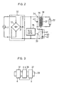
- Fig. 2 illustrates an embodiment of the neon tube lighting device of the present invention.
- the output of the commercial power supply 11 is applied to the full-wave rectifier 12, the output of which is provided to the capacitor 31.
- the full-wave rectifier 12 and the capacitor 31 constitute a DC power supply 32.
- a resonance circuit 34 is connected across the DC power supply 32 via a MOS FET 33 which serves as a switching element.
- the output signal from a signal generator 35 is applied to the gate of the FET 33 to effect its ON-OFF control.
- the signal generator 35 creates a rectangular wave signal of 14 kHz frequency and a 50% duty cycle, for example.
- the resonance circuit 34 resonates with the output signal frequency of the signal generator 35.
- a resistor 41 and a capacitor 42 form a protective circuit 40 for the FET 33.
- Reference numeral 38 indicates a leakage transformer which uses the winding of the resonance circuit 34 as its primary winding and has its secondary winding 37 connected to the neon tube 22.
- the magnetic circuit of the leakage transformer 38 is an open circuit.
- the primary winding 36 is wound on a ferrite rod 39 and the secondary winding 37 is wound thereon at either side of the primary winding 36.
- the DC voltage of the DC power supply 32 is turned ON and OFF by the ON-OFF operation of the FET 33, by which a high voltage of a high frequency is induced in the secondary winding 37 of the leakage transformer 38, energizing the neon lamp 22 to light.
- a constant-current characteristic can be obtained by use of the leakage transformer 38. Consequently, even if the neon tube 22 shows a short, the load current will not increase, causing no excessive current flow in the FET 33. Furthermore, since a constant current flow is generated regardless of a change in the total load with the length of the neon tube 22 or the number of tubes connected in series, the neon tube 22 is lighted with fixed brightness. Moreover, since the ON-OFF operation of the FET 33 is controlled by the output signal of the signal generator 35 and since the signal generator 35 yields a signal of a stable frequency independently of load variations, a more stable constant-current characteristic can be obtained. In other words, the constant-current characteristic of the leakage transformer 38 varies using frequency as a parameter, but since the ON-OFF frequency of the FET 33 is held constant, an excellent constant-current characteristic can be achieved.
- the neon tube lighting device of the present invention enables the neon tube to produce a stable and uniform discharge without generating the so-called stripe pattern.
- the output of the DC power supply 32 is the full-wave rectified output of a sine-wave voltage.
Landscapes
- Engineering & Computer Science (AREA)
- Power Engineering (AREA)
- Circuit Arrangements For Discharge Lamps (AREA)
- Control Of Indicators Other Than Cathode Ray Tubes (AREA)
Abstract
Description
- The present invention relates to a neon tube lighting device which lights a neon tube by means of a high-frequency, high-voltage power supply.
- A conventional neon tube lighting device of this kind has such a circuit arrangement as shown in Fig. 1. The AC output of a
commercial power source 11 is rectified by a full-wave rectifier 12, the rectified output from which is smoothed by asmoothing circuit 13, the output from which is, in turn, provided to a series circuit oftransistors 14 and 15 and a series circuit ofcapacitors 16 and 17. Aprimary winding 19 of atransformer 18 is connected between the connection point of thetransistors 14 and 15 and the connection point of thecapacitors 16 and 17, aneon tube 22 is connected across asecondary winding 21 of thetransformer 18, and both ends of atertiary winding 23 of thetransformer 18 are connected to the bases of thetransistors 14 and 15, respectively, thus constituting a feedback circuit. Thetransistors 14 and 15, thecapacitors 16 and 17, and thewindings transformer 18 constitutes a closed magnetic circuit. - In the conventional neon tube lighting device depicted in Fig. 1, shorting of a load, i.e. the
neon tube 22 reduces the impedance of thetransformer 18 to zero and an excessive current flows through thetransistors 14 and 15, breaking them down. To prevent this, some protective circuit is needed. The total load changes with the length of theneon tube 22 and the number of such tubes connected, and the power source current also changes to vary the brightness of theneon tube 22. With such a load variation, the oscillation frequency of the oscillator is liable to vary since it is a self-excited oscillator. Even if it is provided with a constant-current characteristic by use of a leakage transformer as thetransformer 18, the constant-current characteristic itself varies. - Furthermore, the neon tube lighting device shown in Fig. 1 is defective in that the neon lamp lacks stability in discharge. Especially, a decrease in the tube diameter of the lamp and an increase in its current density will both lead to the generation of an irregular discharge and what is called a stripe pattern. When the tube current is 15 mA, a
neon tube 15 mm in diameter does not produce the stripe pattern, but a neon tube of 6 mm diameter produces it; when the tube current is 30 mA, the both tubes generate the stripe pattern. - It is therefore an object of the present invention to provide a neon tube lighting device which is free from the above-said defects of the prior art.
- According to the present invention, a resonance circuit is connected across a DC power supply via a switching element, which is placed under ON-OFF control of the output signal from a signal generator. A leakage transformer is employed which uses the winding of the resonance circuit as its primary winding and has its secondary winding connected to a neon tube.
- Since the leakage transformer has a constant-current characteristic, a change in the load will not cause a change in the brightness of the neon tube and a short of the load will not cause an increase in the power supply current. In addition, since no self-excited oscillator is employed, the ON-OFF frequency of the switching element is free from the influence of variations in the load, ensuring an excellent constant-current characteristic.
-
- Fig. 1 is a connection diagram showing a conventional neon tube lighting device;
- Fig. 2 is a connection diagram illustrating an embodiment of the neon tube lighting device of the present invention; and
- Fig. 3 is a schematic diagram showing a
leakage transformer 38 for use in the present invention. - Fig. 2 illustrates an embodiment of the neon tube lighting device of the present invention. The output of the
commercial power supply 11 is applied to the full-wave rectifier 12, the output of which is provided to thecapacitor 31. The full-wave rectifier 12 and thecapacitor 31 constitute aDC power supply 32. Aresonance circuit 34 is connected across theDC power supply 32 via a MOS FET 33 which serves as a switching element. The output signal from asignal generator 35 is applied to the gate of theFET 33 to effect its ON-OFF control. Thesignal generator 35 creates a rectangular wave signal of 14 kHz frequency and a 50% duty cycle, for example. Theresonance circuit 34 resonates with the output signal frequency of thesignal generator 35. A resistor 41 and acapacitor 42 form aprotective circuit 40 for theFET 33. -
Reference numeral 38 indicates a leakage transformer which uses the winding of theresonance circuit 34 as its primary winding and has itssecondary winding 37 connected to theneon tube 22. The magnetic circuit of theleakage transformer 38 is an open circuit. For example, as shown in Fig. 3, theprimary winding 36 is wound on aferrite rod 39 and thesecondary winding 37 is wound thereon at either side of theprimary winding 36. - The DC voltage of the
DC power supply 32 is turned ON and OFF by the ON-OFF operation of theFET 33, by which a high voltage of a high frequency is induced in thesecondary winding 37 of theleakage transformer 38, energizing theneon lamp 22 to light. - With the neon tube lighting device of the present invention described above, a constant-current characteristic can be obtained by use of the
leakage transformer 38. Consequently, even if theneon tube 22 shows a short, the load current will not increase, causing no excessive current flow in theFET 33. Furthermore, since a constant current flow is generated regardless of a change in the total load with the length of theneon tube 22 or the number of tubes connected in series, theneon tube 22 is lighted with fixed brightness. Moreover, since the ON-OFF operation of theFET 33 is controlled by the output signal of thesignal generator 35 and since thesignal generator 35 yields a signal of a stable frequency independently of load variations, a more stable constant-current characteristic can be obtained. In other words, the constant-current characteristic of theleakage transformer 38 varies using frequency as a parameter, but since the ON-OFF frequency of theFET 33 is held constant, an excellent constant-current characteristic can be achieved. - Besides, the neon tube lighting device of the present invention enables the neon tube to produce a stable and uniform discharge without generating the so-called stripe pattern. The output of the
DC power supply 32 is the full-wave rectified output of a sine-wave voltage. The experiment conducted on the neon tube lighting device of the present invention in which the peak voltage of the DC power supply was around 140 V, its dip voltage was around 20 V, the output of thesignal generator 35 was a rectangular wave having a frequency of 14 kHz and a duty cycle of 50%, the tube current was 15 mA, the capacitance of thecapacitor 43 of theresonance circuit 34 was 0.033 µF, the number of turn of the primary andsecondary windings neon tube 22 was 6mm, stable lighting of the neon tube could be achieved without generating variations in discharge and any stripe pattern. - It will be apparent that many modifications and variations may be effected without departing from the scope of the novel concepts of the present invention.
Claims (6)
a resonance circuit connected across a DC power supply via a switching element;
a signal generator which generates a signal for effecting ON-OFF control of the switching element; and
a leakage transformer which uses a winding of the resonance circuit as its primary winding and has its secondary winding connected to a neon tube.
Applications Claiming Priority (2)
| Application Number | Priority Date | Filing Date | Title |
|---|---|---|---|
| JP1987181376U JPH0185894U (en) | 1987-11-27 | 1987-11-27 | |
| JP181376/87 | 1987-11-27 |
Publications (2)
| Publication Number | Publication Date |
|---|---|
| EP0317698A1 true EP0317698A1 (en) | 1989-05-31 |
| EP0317698B1 EP0317698B1 (en) | 1992-07-29 |
Family
ID=16099648
Family Applications (1)
| Application Number | Title | Priority Date | Filing Date |
|---|---|---|---|
| EP88105100A Expired EP0317698B1 (en) | 1987-11-27 | 1988-03-29 | Neon tube lighting device |
Country Status (5)
| Country | Link |
|---|---|
| US (1) | US4891561A (en) |
| EP (1) | EP0317698B1 (en) |
| JP (1) | JPH0185894U (en) |
| CA (1) | CA1296380C (en) |
| DE (1) | DE3873276T2 (en) |
Cited By (4)
| Publication number | Priority date | Publication date | Assignee | Title |
|---|---|---|---|---|
| EP0440244A3 (en) * | 1990-01-31 | 1993-01-07 | Toshiba Lighting & Technology Corporation | Discharge lamp lighting apparatus |
| EP0681415A1 (en) * | 1994-05-06 | 1995-11-08 | Valeo Vision | Device for operating a discharge lamp, especially for inside lighting or signalling of vehicles |
| WO1999062305A1 (en) * | 1998-05-22 | 1999-12-02 | Ideas Electronics (S) Pte Ltd. | Apparatus for supplying electrical power to a discharge lamp |
| WO2007102106A2 (en) | 2006-03-06 | 2007-09-13 | Philips Intellectual Property & Standards Gmbh | Supply circuit and device comprising a supply circuit |
Families Citing this family (5)
| Publication number | Priority date | Publication date | Assignee | Title |
|---|---|---|---|---|
| US5045760A (en) * | 1990-05-29 | 1991-09-03 | Williams Sign Supplies Ltd. | Neon sign transformer |
| US5097182A (en) * | 1990-10-19 | 1992-03-17 | Kelly Allen D | Power supply for a gas discharge lamp |
| US5231333A (en) * | 1990-11-14 | 1993-07-27 | Neon Dynamics, Inc. | Switching excitation supply for gas discharge tubes having means for eliminating the bubble effect |
| US5386181A (en) * | 1992-01-24 | 1995-01-31 | Neon Dynamics Corporation | Swept frequency switching excitation supply for gas discharge tubes |
| US6121732A (en) * | 1997-05-06 | 2000-09-19 | Inshore Holdings, Llc | Neon lamp power supply for producing a bubble-free discharge without promoting mercury migration or premature core saturation |
Citations (4)
| Publication number | Priority date | Publication date | Assignee | Title |
|---|---|---|---|---|
| US3621331A (en) * | 1969-01-08 | 1971-11-16 | Cox & Co Inc | Arrangement for igniting and operating gaseous discharge lamps |
| US4129805A (en) * | 1977-12-05 | 1978-12-12 | Sherman Eli H | Impulse generator for use with phosphor energizable lamps |
| DE2934942A1 (en) * | 1979-08-29 | 1981-04-02 | Siemens AG, 1000 Berlin und 8000 München | Gas laser ignition and operating circuit - has transformer with constant or variable frequency circuit using switching transistor in primary winding |
| WO1983000271A1 (en) * | 1981-07-06 | 1983-01-20 | Zelina, William, B. | Line operated fluorescent lamp inverter ballast |
Family Cites Families (8)
| Publication number | Priority date | Publication date | Assignee | Title |
|---|---|---|---|---|
| US3525900A (en) * | 1965-03-04 | 1970-08-25 | Microdot Inc | Frequency controlled enhancement of light emission |
| US4348615A (en) * | 1980-07-01 | 1982-09-07 | Gte Products Corporation | Discharge lamp operating circuit |
| US4331905A (en) * | 1980-10-27 | 1982-05-25 | General Electric Company | Starting and operating circuit for gaseous discharge lamps |
| US4318170A (en) * | 1981-01-12 | 1982-03-02 | Cabalfin Rolando V | Power inverter oscillator circuit |
| US4472661A (en) * | 1982-09-30 | 1984-09-18 | Culver Clifford T | High voltage, low power transformer for efficiently firing a gas discharge luminous display |
| US4585974A (en) * | 1983-01-03 | 1986-04-29 | North American Philips Corporation | Varible frequency current control device for discharge lamps |
| US4663570A (en) * | 1984-08-17 | 1987-05-05 | Lutron Electronics Co., Inc. | High frequency gas discharge lamp dimming ballast |
| JPS61156697A (en) * | 1984-12-28 | 1986-07-16 | 東芝ライテック株式会社 | Discharge lamp lighting apparatus |
-
1987
- 1987-11-27 JP JP1987181376U patent/JPH0185894U/ja active Pending
-
1988
- 1988-03-09 US US07/165,958 patent/US4891561A/en not_active Expired - Lifetime
- 1988-03-29 EP EP88105100A patent/EP0317698B1/en not_active Expired
- 1988-03-29 DE DE8888105100T patent/DE3873276T2/en not_active Expired - Lifetime
- 1988-04-11 CA CA000563761A patent/CA1296380C/en not_active Expired - Lifetime
Patent Citations (4)
| Publication number | Priority date | Publication date | Assignee | Title |
|---|---|---|---|---|
| US3621331A (en) * | 1969-01-08 | 1971-11-16 | Cox & Co Inc | Arrangement for igniting and operating gaseous discharge lamps |
| US4129805A (en) * | 1977-12-05 | 1978-12-12 | Sherman Eli H | Impulse generator for use with phosphor energizable lamps |
| DE2934942A1 (en) * | 1979-08-29 | 1981-04-02 | Siemens AG, 1000 Berlin und 8000 München | Gas laser ignition and operating circuit - has transformer with constant or variable frequency circuit using switching transistor in primary winding |
| WO1983000271A1 (en) * | 1981-07-06 | 1983-01-20 | Zelina, William, B. | Line operated fluorescent lamp inverter ballast |
Cited By (9)
| Publication number | Priority date | Publication date | Assignee | Title |
|---|---|---|---|---|
| EP0440244A3 (en) * | 1990-01-31 | 1993-01-07 | Toshiba Lighting & Technology Corporation | Discharge lamp lighting apparatus |
| EP0681415A1 (en) * | 1994-05-06 | 1995-11-08 | Valeo Vision | Device for operating a discharge lamp, especially for inside lighting or signalling of vehicles |
| FR2719734A1 (en) * | 1994-05-06 | 1995-11-10 | Valeo Vision | Discharge lamp supply device, especially for interior lighting or vehicle signaling. |
| WO1999062305A1 (en) * | 1998-05-22 | 1999-12-02 | Ideas Electronics (S) Pte Ltd. | Apparatus for supplying electrical power to a discharge lamp |
| WO2007102106A2 (en) | 2006-03-06 | 2007-09-13 | Philips Intellectual Property & Standards Gmbh | Supply circuit and device comprising a supply circuit |
| WO2007102106A3 (en) * | 2006-03-06 | 2007-11-15 | Philips Intellectual Property | Supply circuit and device comprising a supply circuit |
| RU2427954C2 (en) * | 2006-03-06 | 2011-08-27 | Конинклейке Филипс Электроникс Н.В. | Feed circuit and device containing feed circuit |
| CN101395791B (en) * | 2006-03-06 | 2012-07-04 | 皇家飞利浦电子股份有限公司 | Supply circuit and device comprising a supply circuit |
| US8330391B2 (en) | 2006-03-06 | 2012-12-11 | Koninklijke Philips Electronics N.V. | Supply circuit and device comprising a supply circuit |
Also Published As
| Publication number | Publication date |
|---|---|
| DE3873276T2 (en) | 1992-12-03 |
| JPH0185894U (en) | 1989-06-07 |
| DE3873276D1 (en) | 1992-09-03 |
| US4891561A (en) | 1990-01-02 |
| EP0317698B1 (en) | 1992-07-29 |
| CA1296380C (en) | 1992-02-25 |
Similar Documents
| Publication | Publication Date | Title |
|---|---|---|
| KR100289019B1 (en) | Lamp ballast circuit | |
| US4189663A (en) | Direct current ballasting and starting circuitry for gaseous discharge lamps | |
| US6710551B2 (en) | High-intensity discharge lamp lighting apparatus and luminaire for using the same | |
| EP0576991B1 (en) | Control apparatus of fluorescent lamp | |
| GB2104318A (en) | Starting and operating loads with changing impedance characteristics | |
| US4891561A (en) | Neon tube lighting device | |
| KR940009518B1 (en) | Discharge lamp lighting device | |
| GB2204751A (en) | Discharge lamp circuits | |
| US5477112A (en) | Ballasting network with integral trap | |
| JP2604707Y2 (en) | Igniter for starting discharge lamp | |
| JP2000116154A (en) | Method and apparatus for acquisition of power supply by double resonance circuit | |
| GB2093613A (en) | D.C. power supply | |
| JP3122146B2 (en) | Discharge lamp lighting device | |
| JP3136108B2 (en) | Lighting device for discharge lamp | |
| JP2579376B2 (en) | Discharge lamp lighting device | |
| JP2649428B2 (en) | Gas laser device | |
| JPH0613187A (en) | Discharge lamp lighting device | |
| KR930011848B1 (en) | Gain-Adjustable Electronic Ballast Device | |
| JP2707356B2 (en) | Gas laser device | |
| JPH03147295A (en) | discharge lamp lighting device | |
| GB2151090A (en) | Electronic ballast | |
| JPS60133698A (en) | Power source | |
| JPH03173097A (en) | Discharge lamp lighting device | |
| JPH02256196A (en) | discharge lamp lighting device | |
| JPH07114153B2 (en) | Discharge lamp lighting circuit |
Legal Events
| Date | Code | Title | Description |
|---|---|---|---|
| PUAI | Public reference made under article 153(3) epc to a published international application that has entered the european phase |
Free format text: ORIGINAL CODE: 0009012 |
|
| 17P | Request for examination filed |
Effective date: 19880329 |
|
| AK | Designated contracting states |
Kind code of ref document: A1 Designated state(s): DE GB |
|
| RIN1 | Information on inventor provided before grant (corrected) |
Inventor name: MIZUHATA, YOSHINORI Inventor name: AMANO, SHINTETSU |
|
| 17Q | First examination report despatched |
Effective date: 19910221 |
|
| GRAA | (expected) grant |
Free format text: ORIGINAL CODE: 0009210 |
|
| AK | Designated contracting states |
Kind code of ref document: B1 Designated state(s): DE GB |
|
| REF | Corresponds to: |
Ref document number: 3873276 Country of ref document: DE Date of ref document: 19920903 |
|
| PLBE | No opposition filed within time limit |
Free format text: ORIGINAL CODE: 0009261 |
|
| STAA | Information on the status of an ep patent application or granted ep patent |
Free format text: STATUS: NO OPPOSITION FILED WITHIN TIME LIMIT |
|
| 26N | No opposition filed | ||
| REG | Reference to a national code |
Ref country code: GB Ref legal event code: IF02 |
|
| PGFP | Annual fee paid to national office [announced via postgrant information from national office to epo] |
Ref country code: DE Payment date: 20060329 Year of fee payment: 19 Ref country code: GB Payment date: 20060329 Year of fee payment: 19 |
|
| GBPC | Gb: european patent ceased through non-payment of renewal fee |
Effective date: 20070329 |
|
| PG25 | Lapsed in a contracting state [announced via postgrant information from national office to epo] |
Ref country code: DE Free format text: LAPSE BECAUSE OF NON-PAYMENT OF DUE FEES Effective date: 20071002 |
|
| PG25 | Lapsed in a contracting state [announced via postgrant information from national office to epo] |
Ref country code: GB Free format text: LAPSE BECAUSE OF NON-PAYMENT OF DUE FEES Effective date: 20070329 |