EP0317559B1 - Mobility support device - Google Patents
Mobility support device Download PDFInfo
- Publication number
- EP0317559B1 EP0317559B1 EP87904548A EP87904548A EP0317559B1 EP 0317559 B1 EP0317559 B1 EP 0317559B1 EP 87904548 A EP87904548 A EP 87904548A EP 87904548 A EP87904548 A EP 87904548A EP 0317559 B1 EP0317559 B1 EP 0317559B1
- Authority
- EP
- European Patent Office
- Prior art keywords
- support device
- mobile support
- frame
- frame sections
- wheels
- Prior art date
- Legal status (The legal status is an assumption and is not a legal conclusion. Google has not performed a legal analysis and makes no representation as to the accuracy of the status listed.)
- Expired - Lifetime
Links
- 238000006243 chemical reaction Methods 0.000 claims abstract description 12
- 230000007246 mechanism Effects 0.000 claims description 25
- 238000006073 displacement reaction Methods 0.000 claims description 5
- 230000000295 complement effect Effects 0.000 description 5
- 210000002414 leg Anatomy 0.000 description 4
- 238000012559 user support system Methods 0.000 description 4
- 241001272996 Polyphylla fullo Species 0.000 description 3
- 230000000712 assembly Effects 0.000 description 3
- 238000000429 assembly Methods 0.000 description 3
- 208000006011 Stroke Diseases 0.000 description 2
- 230000004913 activation Effects 0.000 description 2
- 238000009739 binding Methods 0.000 description 2
- 230000006835 compression Effects 0.000 description 2
- 238000007906 compression Methods 0.000 description 2
- 238000013016 damping Methods 0.000 description 2
- 230000000694 effects Effects 0.000 description 2
- 230000002996 emotional effect Effects 0.000 description 2
- 230000002093 peripheral effect Effects 0.000 description 2
- 238000000926 separation method Methods 0.000 description 2
- 229910000906 Bronze Inorganic materials 0.000 description 1
- 239000004677 Nylon Substances 0.000 description 1
- 208000027418 Wounds and injury Diseases 0.000 description 1
- 230000003213 activating effect Effects 0.000 description 1
- 239000010974 bronze Substances 0.000 description 1
- 210000001217 buttock Anatomy 0.000 description 1
- KUNSUQLRTQLHQQ-UHFFFAOYSA-N copper tin Chemical group [Cu].[Sn] KUNSUQLRTQLHQQ-UHFFFAOYSA-N 0.000 description 1
- 239000002537 cosmetic Substances 0.000 description 1
- 230000002354 daily effect Effects 0.000 description 1
- 230000006378 damage Effects 0.000 description 1
- 230000000881 depressing effect Effects 0.000 description 1
- 230000006866 deterioration Effects 0.000 description 1
- 230000001627 detrimental effect Effects 0.000 description 1
- 230000003203 everyday effect Effects 0.000 description 1
- 239000006260 foam Substances 0.000 description 1
- 208000014674 injury Diseases 0.000 description 1
- 229920001778 nylon Polymers 0.000 description 1
- 230000001681 protective effect Effects 0.000 description 1
- 238000005096 rolling process Methods 0.000 description 1
- 125000006850 spacer group Chemical group 0.000 description 1
- 239000003381 stabilizer Substances 0.000 description 1
- 230000036642 wellbeing Effects 0.000 description 1
Images












Classifications
-
- A—HUMAN NECESSITIES
- A61—MEDICAL OR VETERINARY SCIENCE; HYGIENE
- A61H—PHYSICAL THERAPY APPARATUS, e.g. DEVICES FOR LOCATING OR STIMULATING REFLEX POINTS IN THE BODY; ARTIFICIAL RESPIRATION; MASSAGE; BATHING DEVICES FOR SPECIAL THERAPEUTIC OR HYGIENIC PURPOSES OR SPECIFIC PARTS OF THE BODY
- A61H3/00—Appliances for aiding patients or disabled persons to walk about
- A61H3/04—Wheeled walking aids for patients or disabled persons
-
- A—HUMAN NECESSITIES
- A61—MEDICAL OR VETERINARY SCIENCE; HYGIENE
- A61G—TRANSPORT, PERSONAL CONVEYANCES, OR ACCOMMODATION SPECIALLY ADAPTED FOR PATIENTS OR DISABLED PERSONS; OPERATING TABLES OR CHAIRS; CHAIRS FOR DENTISTRY; FUNERAL DEVICES
- A61G5/00—Chairs or personal conveyances specially adapted for patients or disabled persons, e.g. wheelchairs
-
- A—HUMAN NECESSITIES
- A61—MEDICAL OR VETERINARY SCIENCE; HYGIENE
- A61G—TRANSPORT, PERSONAL CONVEYANCES, OR ACCOMMODATION SPECIALLY ADAPTED FOR PATIENTS OR DISABLED PERSONS; OPERATING TABLES OR CHAIRS; CHAIRS FOR DENTISTRY; FUNERAL DEVICES
- A61G5/00—Chairs or personal conveyances specially adapted for patients or disabled persons, e.g. wheelchairs
- A61G5/10—Parts, details or accessories
- A61G5/1094—Tables, working plates or trays
-
- A—HUMAN NECESSITIES
- A61—MEDICAL OR VETERINARY SCIENCE; HYGIENE
- A61G—TRANSPORT, PERSONAL CONVEYANCES, OR ACCOMMODATION SPECIALLY ADAPTED FOR PATIENTS OR DISABLED PERSONS; OPERATING TABLES OR CHAIRS; CHAIRS FOR DENTISTRY; FUNERAL DEVICES
- A61G5/00—Chairs or personal conveyances specially adapted for patients or disabled persons, e.g. wheelchairs
- A61G5/10—Parts, details or accessories
- A61G5/12—Rests specially adapted therefor, e.g. for the head or the feet
- A61G5/125—Rests specially adapted therefor, e.g. for the head or the feet for arms
-
- A—HUMAN NECESSITIES
- A61—MEDICAL OR VETERINARY SCIENCE; HYGIENE
- A61G—TRANSPORT, PERSONAL CONVEYANCES, OR ACCOMMODATION SPECIALLY ADAPTED FOR PATIENTS OR DISABLED PERSONS; OPERATING TABLES OR CHAIRS; CHAIRS FOR DENTISTRY; FUNERAL DEVICES
- A61G5/00—Chairs or personal conveyances specially adapted for patients or disabled persons, e.g. wheelchairs
- A61G5/10—Parts, details or accessories
- A61G5/12—Rests specially adapted therefor, e.g. for the head or the feet
- A61G5/128—Rests specially adapted therefor, e.g. for the head or the feet for feet
-
- A—HUMAN NECESSITIES
- A61—MEDICAL OR VETERINARY SCIENCE; HYGIENE
- A61H—PHYSICAL THERAPY APPARATUS, e.g. DEVICES FOR LOCATING OR STIMULATING REFLEX POINTS IN THE BODY; ARTIFICIAL RESPIRATION; MASSAGE; BATHING DEVICES FOR SPECIAL THERAPEUTIC OR HYGIENIC PURPOSES OR SPECIFIC PARTS OF THE BODY
- A61H3/00—Appliances for aiding patients or disabled persons to walk about
- A61H2003/002—Appliances for aiding patients or disabled persons to walk about with attached or incorporated article carrying means
- A61H2003/004—Trays
-
- A—HUMAN NECESSITIES
- A61—MEDICAL OR VETERINARY SCIENCE; HYGIENE
- A61H—PHYSICAL THERAPY APPARATUS, e.g. DEVICES FOR LOCATING OR STIMULATING REFLEX POINTS IN THE BODY; ARTIFICIAL RESPIRATION; MASSAGE; BATHING DEVICES FOR SPECIAL THERAPEUTIC OR HYGIENIC PURPOSES OR SPECIFIC PARTS OF THE BODY
- A61H3/00—Appliances for aiding patients or disabled persons to walk about
- A61H3/04—Wheeled walking aids for patients or disabled persons
- A61H2003/046—Wheeled walking aids for patients or disabled persons with braking means
-
- A—HUMAN NECESSITIES
- A61—MEDICAL OR VETERINARY SCIENCE; HYGIENE
- A61H—PHYSICAL THERAPY APPARATUS, e.g. DEVICES FOR LOCATING OR STIMULATING REFLEX POINTS IN THE BODY; ARTIFICIAL RESPIRATION; MASSAGE; BATHING DEVICES FOR SPECIAL THERAPEUTIC OR HYGIENIC PURPOSES OR SPECIFIC PARTS OF THE BODY
- A61H2201/00—Characteristics of apparatus not provided for in the preceding codes
- A61H2201/16—Physical interface with patient
- A61H2201/1602—Physical interface with patient kind of interface, e.g. head rest, knee support or lumbar support
- A61H2201/1614—Shoulder, e.g. for neck stretching
-
- A—HUMAN NECESSITIES
- A61—MEDICAL OR VETERINARY SCIENCE; HYGIENE
- A61H—PHYSICAL THERAPY APPARATUS, e.g. DEVICES FOR LOCATING OR STIMULATING REFLEX POINTS IN THE BODY; ARTIFICIAL RESPIRATION; MASSAGE; BATHING DEVICES FOR SPECIAL THERAPEUTIC OR HYGIENIC PURPOSES OR SPECIFIC PARTS OF THE BODY
- A61H2201/00—Characteristics of apparatus not provided for in the preceding codes
- A61H2201/16—Physical interface with patient
- A61H2201/1602—Physical interface with patient kind of interface, e.g. head rest, knee support or lumbar support
- A61H2201/1628—Pelvis
- A61H2201/1633—Seat
Definitions
- the present invention relates to a mobile support device, according to the first part of claims 1 and 26, respectively.
- a mobile support device is disclosed in the documents US-A-3788695 and US-A-1 611 807, respectively.
- walkers are available providing bodily support to the patients.
- Such devices are often large and bulky and require the patient to be entrapped within the structure, resulting in a mobility aid which, although assisting the patient, is conspicuous and therefore detrimental to the patients emotional well-being.
- U.S. patent 1,116,807 to Bergh illustrates an exercising device which has a castered frame, a harness that supports the patient in a standing position and a retractable seat.
- U.S. Patent Specification No. 5892,282 to Duke also illustrates an exercising device with a castered frame and a retractable seat. However, in both cases, the frame is bulky leading the device to be unsuitable to many patients with limited strength.
- U.S. Patent 3,788,695 to Salem illustrates a sitting/standing Table/walker combination that has the seat and back portions of a chair and a wheeled undercarriage with front and rear caster wheels.
- a tray is provided to secure the patient in the chair.
- Salem's device is also provided with a base plate to restrain the feet of the patient.
- This chair is generally unsuitable for many patients with limited strength since its undercarriage cannot offer the degree of directional control needed for such patients if they are to mobile on their own.
- the invention provides a mobile support device having the features set out in the characterising portion of claims 1 and 26, respectively.
- a mobility device 10 is shown in the form of a chair having a frame 12 which supports seat 14 and a back rest 16, with the seat being inclined at approximately six degrees from the horizontal axis, and the back rest 16 inclined 15 degrees from the vertical axis.
- the chair has a pair of arms 18, 20 the former being pivotal and the latter being retractable as will be described.
- a tray 22 is mounted on the front of the arms 18, 20 and provides a working surface as well as a protective gate and hand grip.
- a carrying hamper 23 hangs from the arm 20 for carrying magazines or other articles.
- a wheel assembly 24 is provided on the bottom of the chair which is controlled by a pair of braking handles 26 which activate a braking mechanism 28 as will be described.
- a pair of adjustable foot rests 30 are mounted on the frame 12 as will be described, with restraint being provided to the user by a seat belt 32 extending from the seat. As well, the seat is pivotable and height adjustable as will be later explained.
- the frame is formed from left and right frame sections 34, 36 both being of an "S"-shaped configuration.
- Each of the left and right frame sections have a lower horizontal portion 34a, 36a to support the wheel assembly, a lower corner portion 34b, 36b to support the foot rests 30, a middle portion 34c, 36c to support the seat 14 and back rest 16, and an upper portion 34d, 36d to support the tray 22 and also to form the arms 18, 20 of the chair.
- the middle portion 34c, 36c serves as a location for frame disassembly, as shown in Figure 3. This is provided by way of the middle portion being formed from two parts, a first segment, for example 34e, having a swaged end of reduced diameter for telescoping engagement with the end of a second segment 34f.
- each of the arms 18, 20 is also provided with a pair of arm rests 42, while the tray 22 is pivotally connected to the left arm 18 and releasably positioned on the right arm 20.
- the lateral edges 22a of the tray are concave thereby providing sufficient area for a working surface while enabling the patient to grip the central region of the tray 22 with his hands.
- the right arm 20 is easily retractable, and is formed from first and second right arm portions 20a, 20b the first portion 20a having a swaged end region for telescoping engagement with the end of the second right arm portion 20b.
- a restraint mechanism 44 is provided in the first right arm portion 40a and is seen as a ball 44a nested in a hole 20c and biased therein by way of a compression spring, 44b with the ball extending from the hole so as to extend into a hole 20d formed in the second right hand portion 20b.
- the left arm 18 While the right arm 20 is retractable, the left arm 18 is pivotal between a usable position and a storage position.
- the left arm 18 has a first left arm portion 18a pivotally connected to a second left arm portion 18a at a pivot connection identified at 45.
- the end of the first left arm portion 38a is collapsed to form a substantially "U"-shaped cross-section.
- the first left arm portion 18a is pivotally connected to the second left arm portion 18b by way of an extensible pivot member 46 extending through co-axial bores 18c, 18d formed in the first and second left arm portions 18a, 18b respectively.
- the extensible pivot member 46 is formed from a cylinder element 46a closed at one end by a first head 46b with the other end having a bore 46c extending there-through.
- a piston 46d is slidably engaged with the inner surface of the cylinder element 46a and is joined to a shaft 46e which extends through the bore 46c, with the free end of the shaft terminating at a second head 46f.
- a compression spring 46g is located within the cylinder element 46b to bias the piston 46d against the first head 46b, such that rotation of the first left arm portion 38a causes separation thereof from the second left arm portion 38b, and causing the pivot member 46 to extend through the travel of the piston 46d along the cylinder element 46a against the spring 46g.
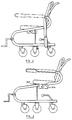
- the pivot connection between the first and second left arm portions 18a, 18b and the pivot connection between the tray 22 and the first left arm portion 18a enables the left arm 18 to be rotated to a convenient storage position as demonstrated in Figures 2, 10, 12 and 13.
- the tray 22 is first rotated to a vertical position as seen by the arrow "A”.
- the first left arm portion is then rotated to an upper vertical position as seen by arrow "B”.
- the tray being returned to its original position relative to the first left arm portion as seen by arrow "C”.
- the arm is rotated to a lower storage position as seen by the arrow "D".
- the configuration embodied in the left arm 18 enables the patient to store the tray thereby providing the patient with the capability of sitting at a table, or of accessing the chair from the side.
- the first right arm portion 20a is easily retractable by depressing the ball 44a through the hole 20d and subsequently removing the swaged end of the first right arm portion 20a from the second right arm portion 20b.
- FIG. 1 Another particular feature of the chair 10 is the wheel assembly 24 as seen in Figure 1 which is coupled to the lower horizontal portions 34a, 36a of the left and right frame sections 34, 36.
- Three wheels, for example wheels 48, 50, 53 are used on each of the lower horizontal portions, for example 34a, the front and rear wheels 48, 50 thereof providing a swivel movement with respect to the lower horizontal portion 34a.
- the intermediate wheel 53 on the other hand is constrained to rotation about an axis perpendicular to the lower horizontal portion 34a. In this configuration, the intermediate wheels 53 prevent lateral displacement of the chair relative to the floor while permitting increased stability and improved directional tracking, as well as the ability to rotate about a fixed point.
- the braking assembly 28 is shown in detail in Figure 8.
- the brakes are manually controlled by braking levers 26 which extend upwardly and forwardly from slots 54 formed in the rear of the lower horizontal portions 34a, 34b.
- Each of the levers 26 are coupled to a first link 56 which is fixed to one end of a pivot rod 58 defining a pivot axis "E", which in turn is rotatably mounted at both ends to the horizontal portions 34a, 34b.
- the pivot rod 58 conveniently extends in a concealed manner within a spanner member 60 joining the left and right lower horizontal portions 34a, 34b.
- the first link 56 is pivotally connected to one end 62a of a second link 62 at a pivot identified at "F" which extends along the inner cavity of the lower horizontal portion 34a, with the opposite end 62b being pivotally connected to one end 64a of a braking link 64.
- the lower portion of the braking link extends downwardly to a pivot pin 66 on which the braking link pivots relative to the lower horizontal portion.
- the braking link extends past the pivot pin and outward from a slot 68 formed in the lower region of the horizontal portion 34a.
- Joined to the other end 64b of the braking link 64 is a brake pad 69 of an arcuate shape so as to contact the floor contacting surface 53a of the intermediate wheel 53.
- the braking assembly 28 provides simultaneous braking of both left and right intermediate wheels 53 by rotation of either braking lever 26.
- the pivot points are selected in the first link such that the pivot point "F" of the second link is “over-center” with respect to the pivot axis "E” of the pivot rod 58.
- the braking assembly 28 provides a self-locking mechanism whereby the braking lever 26 is rotated toward contact with the rear edge of the slot 54. This corresponds to a point where the pivot point "F” is located above axis "E", thereby causing the reaction force, exerted by the wheel 54 and transmitted through the mechanism 28, to maintain the lever 26 in the locked position against the rear edge of the slot.
- the braking mechanism 28 is capable of providing a constant light braking force to the middle wheels for a controlled substantially unaccelerated travel down an incline.
- This is provided by an arcuate bracket 70 which is fixed to the lower horizontal portion 34a of the frame adjacent to the central region of a brake lever 26.
- the bracket 70 has a number of notches 70a formed therein to enable the lever 26 to be locked in a particular orientation so as to provide a constant braking force against the intermediate wheel 53.
- the extent of rotation of the lever 26 to maintain substantially unaccelerated travel increases with the degree of incline being traversed.
- the pivot rod 66 may be located on the frame 53b of the wheel rather than on the lower horizontal portion 34a, thereby providing relatively shorter distance of travel of the brake pad 69.
- the chair is also provided with a seat 14 which is pivotal and height adjustable by way of a height adjustment mechanism 74 illustrated in Figures 6 and 7.
- the seat is pivotally mounted via a pair of first support blocks 76 to a tubular shaft 78, the shaft being held at each end by a second support element 80.
- Adjacent the second support element 80 is a rack element 82 of a rack and pinion arrangement, the pinion 84 being fixed to a rod 86 which extends through a slot 80a formed in the second support element 80.
- Both the second support element 80 and the rack element 82 are fixed to a transverse frame element 88.
- a plate element 90 Positioned adjacent the second support element is a plate element 90 having a centrally located slot 104, through which the rod 86 extends.
- a pair of guides 92 extend downwardly along the inner surface of the plate so as to engage with the front and rear edges 80b, 80c of the second support element 80.
- Fixed to the end of the rod 86 is a knob 94 for rotation of the rod 86 and accordingly the pinion 84 along the rack element 82.
- the region of the rod 86 between the knob 94 and the plate 90 is threaded to engage threadably with a release latch 96, which releasably maintains the rod 86 in position.
- the height adjustment mechanism provides facilitated adjustment of the seat 14 relative to the frame 12, by way of rotating the release latch 96 and subsequently turning the knob 94. This causes relative displacement between the rack element 82 and the pinion 84, and results in the support element 80 travelling along the guide 92.
- a further mechanism is provided on the seat to dampen sudden rotations of the seat relative to the shaft.
- an air cylinder 98 is joined to the central region of the rear of the seat 14 and to a support frame 100 which includes an arm 100a extending rearwardly from the transverse frame member 88 and a brace 100b joining the arm 100a with the shaft 78.
- FIG. 6 Another embodiment is shown in dashed lines in Figure 6 wherein the seat is pivotally mounted on shaft 86 by way of support blocks 102 in lieu of support blocks 76 and shaft 78.
- the rack element 82 and the support block 80 are fixedly mounted to plate element 90 while shaft 86 is displaced relative to plate 90 by extending through the slot 104, thereby eliminating the need for guides 92 and transverse frame element 88.
- a support frame 106 is pivotally mounted on shaft 86 in lieu of support frame 100.
- support frame 106 includes a support block 107 pivotally mounted on the shaft 86 adjacent each pinion element 84.
- Projections 108 extend from the upper and lower portions of support block 107, adjacent to but not contacting the teeth of pinion 84, and extend through the slots 80a. In this manner, support block 107 displaces in concert with the rod 86 but does not rotate therewith. Extending rearwardly from each of the support blocks 107 is a frame member 109 which terminates at a junction with a frame member 109a which extends toward connection with the air cylinder 98.
- a tension spring 97 is located adjacent the air cylinder 98 to bias the seat to its rearwardly inclined position.
- a rotation limit device 99 is located adjacent the air cylinder 98 to restrict the rearward and forward rotation of the seat to the desired six degrees with respect to the horizontal.
- the limit device includes an elongate element 99a having a slot 99b which is connected to the rear portion of the seat.
- a member 99c with a pin 99d is coupled to the arm 100a.
- the chair is also provided with adjustable foot rest 30 as are shown in detail in Figures 14 and 15.
- the foot rest 30 includes an angular member 110 having a shaft 112 connected to one end 110a.
- a foot pad 114 is pivotally connected to the shaft 112 for movement between a horizontal position and a vertical position.
- Magnets 116 are further provided both on the foot pad 114 and the angular member 110 to maintain the foot pad 114 in a vertical position.
- the angular member is in turn joined to the lower corner portion 34b by a wing nut 115, and maintained in a given orientation by a pair of interconnecting discs 116, 118.
- each of the discs has transversely extending triangular teeth 120 which mesh upon engagement of the discs 116, 118, with the disc 116 being fixed to the angular member, and the other disc 118 being fixed to the lower corner portion 34b.
- the discs 118, 116 are also respectively provided with a pin 122 and recess 124 as shown in Figure 15 to enable inter-engagement of the discs within predetermined limits, thereby preventing the foot rest 30 from contacting the floor, and interferring with the mobility of the chair.
- FIG. 21 An alternative foot rest 125 is shown in Figure 21 wherein a right angled member 126 extends from the inter-engaged discs 116, 118 and terminates at a crown gear element 127 rotatably mounted circumferentially thereon.
- the crown gear is threadably engaged with a threaded rod element 128 which includes an elongate rectangular projection 128a extending along the shaft to engage with a complementary recess on the inner edge of the member 126.
- the foot rest 125 is further provided with a pinion element 128b rotatably mounted to the right angled member 126, teeth 128c of which are meshed with the teeth 127a of crown gear 127.
- a knob 129a is also fixed to the pinion element 129 so as to enable the user to cause rotation thereof, which in turn causes the crown gear 127 to rotate and the threaded rod 128 to be displaced relative to the member 126.
- the length of the foot rest 125 is easily adjustable to accommodate users with different leg lengths.
- FIG. 16 to 19 An alternative to the aforementioned height adjustment mechanism 74 of the seat is the height adjustment mechanism 129 shown in Figures 16 to 19.
- the seat is pivotally mounted by a pair of first support blocks 130 to a tubular shaft 132, the shaft being held at each end by a second support block 134.
- the second support block 34 is in turn mounted to a first transverse frame member 136.
- Each end of the transverse frame member 136 is fixed to a slider frame 138, defined by a pair of spaced horizontal flanges 138a, 138b and joined by a vertical web 138c.
- the flanges have centrally located and co-axial bores 138d which receive a threaded shaft 140.
- Threaded on the shaft 140 is a remote sprocket 142 positioned at spaced distances from each of the flanges by upper and lower spacers 144, 146.
- the threaded rod is in turn held in a support frame 148, again defined by a pair of horizontal flanges 148a, 148b and joined by a vertical web 148c.
- each of the support frames 148 is fixed to the central region of the middle portion 34c of the frame sections.
- a chain 150 passes over each of the remote sprockets to a central crank mechanism 152 located in the central region of the transverse frame member.
- the crank mechanism comprises a crank 154 member having an offset cranking knob 154a mounted on a cranking arm 154b.
- the cranking arm is in turn mounted on a shaft 156 to which a sprocket 158 is also mounted.
- the shaft 156 is rotatably mounted in the transverse frame member by way of releasable mounting through a bore 136a and maintained therein by a nut and washer 160.
- rotation of the crank arm 154b via the knob 154a causes the chain 150 to be displaced in a manner which causes rotation of the remote sprockets 142.
- the sprockets 142 By virtue of their threaded engagement with the threaded rods 140, the sprockets 142 then upwardly displace with respect to the threaded rods 140, thereby raising the elevation of the seat.
- an air cylinder 159 mounted at one end on the rear portion of the seat as is shown in Figures 18 and 19.
- the air cylinder is mounted at its other end to a frame assembly 161 extending rearwardly from the shaft 132 and the transverse frame member 136.
- air cylinders 98 and 159 each provide a dampening effect to both forward and rearward locations of the seat. This damping effect could also be provided in one rotative sense only or be greater in one rotative sense than in the other. Oil cylinders are also contemplated as an alternative to the air cylinders.
- a height adjustment mechanism utilizing a rack and pinion arrangement, wherein the rack element thereof is fixed relative to the seat frame, while the axis of pinion element is fixed on a pivot shaft displaced relative to the seat frame.
- the seat may be pivotally mounted on the pivot shaft.
- tray 162 is incorporated with one arm pad, to provide an increased arm support particularly for patients having suffered from a stroke or from other causes, resulting in little strength in one arm.
- a restraint bar in place of the tray.
- the split seat 164 includes a rear section 168 which is mounted to the middle portion 34c of the frame by way of a pair of flanges 168 depending from each side of the rear section 166, which slidably engage with a frame plate 170 mounted on the middle portion 34c.
- a series of holes 170a, 170b are located near the front and rear ends respectively of the frame plate 170 and are in-line with holes 168a, 168b located in the front and rear ends respectively of the flange 168 so as to receive adjustment pins 172.
- a front section 174 is hinged to the rear section 166 and has on each side a downward projection 176 which abuts a cam element 178.
- a second embodiment of the mobility device is shown in the form of a stand-up walker 200 in Figure 22.
- the walker includes a frame 202 which supports a seat 204 pivotal between horizontal and vertical positions and a back rest 206.
- the support includes a releasable restraint bar 208 which assists in supporting the user as will be described.
- a wheel assembly similar to that in the aforementioned embodiment, and identified at 210 is located in the lower end of the frame for mobility while a pair of outriggers 212 extend transversely from the frame and adjacent to the wheels as will be described.
- the stand up walker 200 may also include a braking mechanism in accordance with braking mechanism 28 in the aforementioned embodiment and, in which case, is equipped with length adjustable arms 213.
- the frame structure is formed from left and right frame sections 214, 216, each of an "S"-shaped configuration, to form lower, middle and upper horizontal frame segments 214a, 214b, 214c and 216a, 216b, 216c respectively.
- the lower frame segments combine with a spanning member 218 which extends between the rear region of the lower segments 214a, 216a to form a base, while the upper segments 214c, 216c combine to form the left and right arms of the walker 200.
- Joining each of the lower and middle segments is a first vertical spanner 214d, 216d formed from a pair of telescoping elements which, joined by a bolt configuration identified at 220, so as to provide a walker 200 which may be disassembled.
- Disassembly is also provided by a second vertical spanner 214e, 216e formed from a pair of telescoping elements which, joined by a bolt configuration shown at 221 may be either disassembled or length adjusted.
- the restraint bar 208 is pivotally connected to the left arm 214c, while the opposite end of the restraint bar is coupled to the right arm 216c, by way of a releasable latch 222.
- each end of the lower frame segments Projecting longitudinally from each end of the lower frame segments are collars 224 which engage with the right angled ends 212a of rectangular outriggers 212. Joining the right angled ends thereof is a body member 212b.
- the collars 224 are further provided with a bore 224a which receives a pin to fix the outrigger 212 with the lower surface of the body member having an incremental spacing from the floor surface, for example one half inch.
- the outrigger 212 provides a support against inadvertent tipping of the walker 200.
- the seat 204 is pivotally connected to a pair of brackets 226 immediately below the back rest 206, which in turn is mounted on a fixed cross panel 228.
- the seat 204 provides a support for the patient in a partial sitting position in which, while gripping the arms 214c, 216 or the restraint bar 208 may propel the walker 200.
- the seat may be stored in a vertical position enabling the patient to walk with the support of the walker in a standing position, with further support being provided by a harness 230.
- the harness 230 includes a belt 232 which extends around the central region of the user, and has a releasable buckle in the rear portion thereof.
- the belt 232 is joined to the arms 214c, 216c by way of four expandable belts 234, which are coupled to the arms 214c, 216c by way of releasable brackets 236.
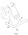
- FIG. 23 An alternative to the fixed outrigger is shown in Figure 23, wherein the pins are omitted from the collars so as to enable the outrigger 212 to rotate therein.
- a first link 240 is pivotally connected between a remote point on the front right angled member shown at 242 and a pivot point in the central region of a second link 244.
- the second link in turn is pivotally coupled to the vertical spanner 214d and has at its remote end, a handle 244a enabling the patient to rotate the second link upwardly in the direction of the arrow identified at "G". In this manner, the outrigger is easily retracted to a stored position, enabling the walker to pass through a doorway.
- a further alternative to the fixed outrigger is an automatically extendable outrigger 250 as shown in Figures 24 and 25.
- the automatic outrigger 250 is formed from a first housing 252 and a second housing 254, the second housing 254 being pivotal relative to the first housing 252, which is secured to the lower frame segment 214a.
- Located on the first housing 252 is an activation rod 256 which is oriented at one end 256a in close proximity with the floor surface, and is slidably engaged within brackets 258 extending near each end thereof from the first housing 252.
- the other end 256b of the activation rod 256 is engaged with a first latch 258 which is pivotally mounted to the first housing 252 and engages a catch 260 formed on the second housing.
- the second housing 254 is tubular and has one end 254a through which outwardly extends a deploy rod 262, which is slidably engaged with the inner surface of the second housing.
- the deploy rod is also biased to an outwardly extended position by way of a spring 263, also within the second housing and engaged with a boss 262a formed in the central region of the deploy rod 262.
- the other end 254b of the second housing has an aperture formed therein, through which the other end of the deploy rod 262b outwardly extends in a stored position as shown in Figure 24.
- the end of the deploy rod is defined by a circumferential groove 262c which engages with the finger 264a of a second latch 264, pivotally mounted to the second housing 254 and biased against the groove by a spring 266.
- the second latch 264 is activated by way of an abutment rod 268 which is positioned in a bracket 270 formed on the first housing 252 and adjusted to the required extension therefrom by way of a set screw 272, so as to engage the other end of the second latch 264 upon rotation of the second housing 254 with respect to the first housing 252 under the biasing force of a coil spring 276 joined therebetween.
- the angle through which the second housing 254 rotates and the relative length of the second housing 254 and the deploy rod 262 are choosen such that in the extended position, the frictional force between the inner wall of the second housing 254 and the second deploy rod 262 provides a binding reaction force, thereby enabling the housing and the deploy rod to function as a unitary support member against the force exerted by the patient against the frame 12 of the walker.
- the deploy rod 278 is formed with a "T"-shaped outward end, providing additional stability while at the same time distributing the force exerted on the deploy rod in its extended position.
- a deploy rod 280 has a "T"-shaped end, with one of the transversely extending arms 280a having a arm 280b extending inwardly at right angles to the transverse arm 280a.
- the inwardly extending arm is oriented at an angle ⁇ with respect to the axis of deploy rod 280, angle ⁇ corresponding to the angle in which the deploy rod 280 is located relative to the horizontal in the outwardly extended position. In this manner the deploy rod 280 provides further support to the outrigger in its extended position located adjacent the front or rear wheel.
- any number of outriggers may be located on the side of the walker.
- a convenient combination involves the placement of an outrigger adjacent each wheel.
- the harness 230 including six or more belts 234 to provide further support to the user.
- the use of different types of belts 230 such that the front belts have a different spring rate constant than the rear belts, thereby providing easier flexibility of the harness in one direction than in the other.
- the use of a higher spring constant in the rear pair of belts enables the user to flex the harness in the rearward direction while preventing the user from flexing the harness in the forward direction, thereby supporting the user against falling forward.
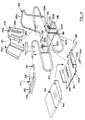
- FIG. 28 to 35 A further embodiment is illustrated in Figures 28 to 35 in the form of a chair 300.
- the chair has a frame 312 on which is positioned a seat 314 and a back 316, with the frame being supported by a wheel assembly 318.
- the wheel assembly 318 is of the same nature as those in the previous embodiments and will hereinafter not be discussed.
- the frame 312 includes arm portions 320a, 320b which are respectively connected to base portions 322a, 322b at an interconnection 324.
- the interconnection is provided by a swaged end formed on each of the arm portions and inserted into the end of the respective base portion.
- a screw element 325 establishes the tight engagement between the respective arm portion and base portion.
- a tray, identified at 328, joins the upper ends of the arm portions 320a, 320b.
- each of the base portions includes an inclined segment 322c and a horizontal segment 322d, with the horizontal segments being joined by a transverse segment 322e.
- the inclined horizontal and transverse segments are joined in continuous fashion and formed by a single tubular element which is bent to form the respective sections.
- a hole 323 In the bent region between the inclined and horizontal segments 322c and 322d respectively is a hole 323 to which is attached a foot rest of the type illustrated in previous embodiments.
- One of a pair of supports 322f joins the respective inclined segment with the adjacent horizontal segment. Pivotally mounted to the support 322f is a back support portion 326 formed of angular segments 326a, 326b which depend from a transverse segment 326c.
- a hole 326d is formed at the remote end of each of the respective angular segments to locate a tightening screw 328 which is threadably engaged with the respective support 322f.
- the horizontal segment 322d is also provided with a support post 330 which carries brackets 332 to locate the back support relative to the frame.
- Each of the brackets 332 includes spaced flanges 332a with a tightening screw 334 threadably engaged with one of the spaced flanges to engage the side wall of a respective angular member.
- the support post 330 is height adjustable by way of a rod portion 330a in threaded engagement with a cylindrical portion 330b.
- the back 316 includes a body 316a formed from a pair of side walls 316b joined to a transverse wall 316c.
- a cushion 316d is coupled to the transverse wall 316c by attaching a pair of complementary Velcro straps 316e located on the rear and front faces respectively of the cushion 316d in the transverse wall 316c.
- the seat 314 is positioned relative to the frame 322 by way of a transverse bar 318 which extends between the supports 322f.
- the seat 314 includes a base 314a having vertical side walls 314b upwardly extending from the lateral edges of a bottom panel 314c, a front portion of which is upwardly inclined in advance of the side walls 314b.
- a pair of brackets 314d engage the lower face of the transverse bar and are attached to the bottom panel 314c.
- a cushion 314e is of a shape complementary to the base 314a, and is connected thereto by way of complementary Velcro straps 314f positioned on the respective surfaces.
- the tray 328 is formed from an outer peripheral frame member 336, the respective ends of which abut the ends of the arm portions 320a, 320b, and an inner peripheral frame member 338 which is padded to offer protection against user injury.
- a panel 339 extends between the inner and outer frame members to provide a working surface.
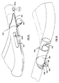
- the tray has a first lateral end, identified at 340 in Figure 32, which locates an insert 342 adjacent a longitudinal slot 344. The slot receives a tightening screw 346 which is threadably engaged with a hole 342a in the insert 342.
- the tray is also provided with a second lateral end 348, shown in Figure 33 in which is welded an insert 350.
- a hole is provided in the lower face of the adjacent arm portion 320a and is identified at 352.
- a support strap 354 Surrounding the hole is a support strap 354 which is threaded with the hole to receive a tightening screw 356 for abutment in an annular groove 358 formed near the remote end of the insert 350. Also formed on the end of the adjacent arm portion 320a is an abutment 360 formed from a bent wire which is welded to the lower face of the arm portion. It is also to be noted that the arm portion 320b is provided with a hole and the appropriate support strap identified at 354a in Figure 32 in order to receive the insert 350 in an alternative configuration as will be described.
- the chair 300 is provided with a dampening mechanism 360 which is of the same form as that utilized in a previous embodiment, and will therefore not be discussed in detail further.
- the chair offers a number of advantages for the user, including a back rest 316 which is easily adjustable relative to the seat 314. This is achieved by simply adjusting the height of the support post 330 to cause the back rest 316 to rotate about supports 322f in the desired manner.
- the back rest also may be easily folded to a horizontal position to reduce the volume needed for shipping, simply by releasing the tightening screw 334 and rotating the back support frame about the supports 322f.
- movement of the seat 314 is dampened by the dampening mechanism.
- rotational limits of the chair may also be provided by way of a rotation limit device, and a spring may be used to bias the seat to a desired orientation.
- the tray also provides an enhanced versatility in that it may be pivoted from the operative position as shown in the drawings to a vertical orientation, depending from arm portion 320a simply by displacing the insert 342 in a forward direction. This is done by releasing tightening screw 346 and displacing the same forward along the slot 344 until the end of the insert 342 is removed from the arm portion 320b. The tray may then be pivoted about the insert 350, by releasing slightly the tightening screw 356. The rotation of the tray beyond the vertical depending orientation is inhibited by the abutment 360.
- the tray 328 has the additional feature in that it may be reversed to permit the tray to be pivoted to a vertical depending position from the arm portion 320b.
- the tightening screw 356 is released from the hole 352 and placed in the appropriately threaded hole and strap 354a as earlier noted.
- the tray is first brought forward to withdraw the inserts 342 and 350 from the respective arm portions, then reversed to enable the inserts 342, 350 to be placed in the opposite arm portions, thereby aligning the annular groove 358 with the repositioned tightening screw 356.
- the seat 314 may be split along a centre line parallel to the central axis of the frame portions, as is shown by dashed lines 354.
- a dampening mechanism 360 would be provided for each of the seat portions formed by such a separation. This would enable independent rotation of the seat segments which is considered particularly important in the case of stroke patients, as well as to geriatric patients, by providing exercise to the upper legs about the hips.
- the support post 330 may be height adjustable to a number of preset heights, thereby allowing the back support portion 326 to be oriented in a corresponding number of preset orientations relative to the chair.
- the chair has a frame assembly 412 including a rear section 414 to support a seat 416, a back 418 and a user support assembly 419, which is also coupled to the seat to allow coordinated movement therebetween as will be described.
- the frame assembly 412 has a pair of right and left hand front sections 420a, 420b which are removably attached to the right and left hand sides respectively of the rear section 414 by a pair of attachment assemblies 422a, 422b.
- the frame assembly 412 also supports the wheel assembly 423 and a foot rest assembly 424, as will be further described.
- the rear section 414 has right hand and left hand segments 426a, 426b respectively which are formed from a continuous tubular member.
- Each of the right hand and left hand segments has an upper portion 428 which is inclined slightly downwardly toward a lower horizontal portion 430, while a central portion 432 joins their respective front ends and is inclined slightly rearwardly from the vertical.
- a back support portion 434 depends from the rear end of the upper portion 428 and has a forwardly cantilevered seat support portion 436.
- An upper transverse member 438 joins the front ends of the seat support portions 436 while a lower transverse member joins the rear ends of the lower portions 430.
- Each of the right and left hand front sections 420a, 420b includes upper and lower portions 444, 446 which are parallel to the respective inclined and horizontal portions of the rear section, and are joined at their front and rear ends respectively by front and rear portions 448, 450 which are oriented parallel relative to the central portion 432.
- attachment assemblies 422a, 422b are shown in more detail in Figure 41 and include a pair of pins 452 extending from the rear face of the rear portions 450 to be inserted into corresponding holes 432a formed in the front face of the central portions 432.
- a ball clamp 454 encompasses the laterally inner and outer peripheries of the central and rear portions and is formed by a pair of clamp segments 454a, 454b. Each of the segments has an inner surface 454c complementary with the outer surface of the respective frame portion, while holes are provided at 454d to receive a tightening screw 454e.
- a rear caster wheel 456 and a middle fixed wheel 458 are provided on the lower portion 430, while a front caster wheel 460 is positioned at the front of the lower portion 446.
- the wheel assembly 423 operates in the same manner as in previous embodiments and will thus not be described further.
- Each of the lower portions 430 also supports a pair of foot rest assemblies 423, which include a foot rest member 423a pivotally mounted on a shaft member 423b, the ends of which are bent so as to be attached to the corresponding inner side face of the lower portion 430.
- a particular feature of the chair 410 is the user support assembly 419 which is illustrated in more detail in Figure 39.
- a support member 462 is pivotally mounted to the upper ball clamp element 454a and to a belt 464, by way of pivot mechanisms 466 and 468.
- the belt 464 is formed from a pair of rigid curved panels 470 with a foam liner 472 attached to each of their inner faces, and a stretchable pad 473 extending between their rear remote ends.
- a pair of straps 476a, 476b extend from the front remote ends of the curved panels 470, with the strap 476b terminating at a buckle 478.
- the user support assembly 419 is adaptable to a number of waist sizes.
- the user support assembly 419 is height adjustable for a wide range of user waist heights.
- FIG. 40 illustrating the pivot mechanism 466 which is attached to the respective curved panel 470 by way of a hole 470a and a corresponding screw 470b extending through the hole to engage a bronze bearing shoulder 470c.
- a bearing surface 470d extends outwardly from the bearing shoulder 470c on which is placed a nylon washer 470e, pivot elements 470f, 470g, a washer 470h and a threaded cap 470i, the threaded cap being threaded to the remote end of the surface 470d.
- the pivot element 470f is fixed to the upper end of the support member 462 while the pivot element 470g is attached to a lever as will be discussed.
- the pivot mechanism 468 is equivalent in structure to the pivot mechanism 466 with the exception that the shoulder 470c is mounted to the inside ball clamp member 454a. In addition, a pivot element corresponding to 470f is not used in pivot mechanism 468. With reference to Figure 42, there is also provided a block 472 affixed to the inner surface of the rear frame portion 450 for limiting forward movement of the support member 462.
- the user enters the chair from the front between the frame sections.
- the support assembly 419 is then strapped around the user's waist, with the appropriate adjustments made for height and width by way of the upper ball clamps 454 and the buckle 478 accordingly.
- the user may then operate the chair in a standing position, wherein the lever member 474 ensures that the seat 414 is in a storage position so as not to interfere with the movement of the user.
- the user is then free to manoeuvre the chair in the desired direction so as to exercise his legs, while grasping the upper frame portions for support.
- the blocks 472 prevent the rotation of the support member 462, thereby preventing his falling forward in the chair.
- the levers 474 are displaced downwardly to cause corresponding rotation of the seat 414 to the operative position.
- the support member 462 ensures the safe alignment of the users buttocks with the seat 414.
- left and right hand front sections 420a, 420b not only reduces the space requirements for shipping, but also allows the chair to be used in one of two configurations.
- the right and left front sections 420a, 420b provide a support rail extending in front of the chair 410, by way of upper portions 444. Being inclined, the support rail allows the user to support himself in a comfortable stance at a range of locations depending on his height, arm length and the like, while at the same time provides additional support for the user when entering the chair 410.
- a further feature of the chair 410 is the inherent flexibility afforded by the rectangular spiral shape of the frame sections 426a, 426b, which serves to absorb vibrations in the rolling surface, while reducing the force of impact should the user fall.
Landscapes
- Health & Medical Sciences (AREA)
- Life Sciences & Earth Sciences (AREA)
- Animal Behavior & Ethology (AREA)
- General Health & Medical Sciences (AREA)
- Public Health (AREA)
- Veterinary Medicine (AREA)
- Epidemiology (AREA)
- Pain & Pain Management (AREA)
- Physical Education & Sports Medicine (AREA)
- Rehabilitation Therapy (AREA)
- Rehabilitation Tools (AREA)
- Vehicle Body Suspensions (AREA)
- Vending Machines For Individual Products (AREA)
- Liquid Crystal Substances (AREA)
- Seal Device For Vehicle (AREA)
- Handcart (AREA)
Abstract
Description
- The present invention relates to a mobile support device, according to the first part of
claims - With the steadily increasing geriatric population and the subsequent number of geriatric care facilities, there has been an increasing awareness of rapid emotional and physical deterioration of their residents due to, among other things, a loss of their independence. A large portion of these residents spend extended periods of time confined to their beds or chairs, and thereby need constant assistance from attending nurses to satisfy their everyday needs.
- This loss in independence is not only seen as a cause for discomfort to the patient and shorter life span, but also results in substantially high costs, associated with the large skilled labour force needed to provide daily care.
- It would therefore be desirable both to the patients and the administrators of the facilities in which they are resident, to provide as much independence as possible to the patients. A significant factor to independence is the mobility of the patient, which is conventionally provided by wheelchairs and rigid frame structures commonly known as "walkers".
- Although providing a certain degree of mobility to the patients, there are several disadvantages associated with such mobility aiding devices. Conventional wheelchairs are bulky and provide a convenience only to those patients with a relatively high degree of arm strength. Those patients who have lost strength in their arms must again demand assistance from the attendants to move from one location to another.
- Conventional walkers appear in two forms, one of which requires the patient to displace the structure forwardly before each step is made and is satisfactory only to those patients with sufficient strength in both the legs and the arms.
- Alternatively, walkers are available providing bodily support to the patients. However, such devices are often large and bulky and require the patient to be entrapped within the structure, resulting in a mobility aid which, although assisting the patient, is conspicuous and therefore detrimental to the patients emotional well-being.
- U.S. patent 1,116,807 to Bergh illustrates an exercising device which has a castered frame, a harness that supports the patient in a standing position and a retractable seat. U.S. Patent Specification No. 5892,282 to Duke also illustrates an exercising device with a castered frame and a retractable seat. However, in both cases, the frame is bulky leading the device to be unsuitable to many patients with limited strength.
- U.S. Patent 3,788,695 to Salem illustrates a sitting/standing Table/walker combination that has the seat and back portions of a chair and a wheeled undercarriage with front and rear caster wheels. A tray is provided to secure the patient in the chair. Salem's device is also provided with a base plate to restrain the feet of the patient. This chair is generally unsuitable for many patients with limited strength since its undercarriage cannot offer the degree of directional control needed for such patients if they are to mobile on their own.
- Accordingly, it is the object of the present invention to provide a novel mobility aid.
- The invention provides a mobile support device having the features set out in the characterising portion of
claims - Further features, objects and advantages of the present invention will be evident from the following detailed description of preferred embodiments, given by way of example only, as seen in the appended drawings in which:
- Figure 1 is a perspective view of a mobility device;
- Figure 2 is a side view of the mobility device, shown in Figure 1, in another configuration;
- Figure 3 is a side view of the mobility device shown in Figure 1 in an alternate configuration;
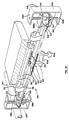
- Figure 4 is a plan view of the mobility device in Figure 1;
- Figure 5 is a plan view of the device shown in Figure 1 with an alternative portion;
- Figure 6 is a partly exploded view of a portion of the mobility device shown in Figure 1;
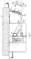
- Figure 7 is a cross-sectional view taken on line 7-7 in Figure 6;
- Figure 8 is a fragmentary perspective view of a portion of the mobility device shown in Figure 1;
- Figure 9 is a perspective assembly view taken with respect to
circle 9 in Figure 1; - Figure 10 is a perspective fragmentary view of another portion of the mobility device shown in Figure 1;
- Figure 11 is a cross-sectional view taken on line 11-11 of Figure 10;
- Figure 12 is a perspective view of the portion shown in Figure 10 in an alternative configuration;
- Figure 13 is a perspective view of the portion shown in Figure 10 in another configuration;
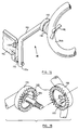
- Figure 14 is a perspective view of another portion of the mobility device shown in Figure 1;
- Figure 15 is a perspective assembly view of a portion of an element shown in Figure 14;
- Figure 16 is a partly exploded assembly view of an alternate configuration of the portion shown in Figure 6;
- Figure 17 is a frontal view of the configuration in Figure 16;
- Figure 18 is a cross-sectional view taken on line 18-18 in Figure 17;
- Figure 19 is an exploded assembly view of several components of the portion shown in Figure 18;
- Figure 20 is a side view of an alternative portion of the device shown in Figure 1;
- Figure 21 is a perspective view of another alternate portion of the device shown in Figure 1;
- Figure 22 is a perspective view of an alternative mobility device;
- Figure 23 is a perspective view of a portion of a alternative mobility device to the device shown in Figure 22;
- Figure 24 is a frontal view of an alternative element of the portion shown in Figure 23;
- Figure 25 is a side view of the element shown in Figure 24;
- Figure 26 is a perspective view of an alternative portion of an element shown in Figure 24;
- Figure 27 is a perspective view of another alternative portion of an element shown in Figure 24;
- Figure 28 is a side view of an alternative mobility device;
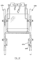
- Figure 29 is a front view taken on
arrow 29 in Figure 28; - Figure 30 is a plan view taken on
arrow 30 of Figure 28; - Figure 31 is an exploded view of a portion of the device illustrated in Figure 28;
- Figure 32 is a fragmentary perspective view of one portion of the device illustrated in Figure 28;
- Figure 33 is a fragmentary perspective view of another portion of the device illustrated in Figure 28;
- Figure 34 is a perspective view of another portion of the device illustrated in Figure 28;
- Figure 35 is an alternative to a portion of the device illustrated in Figure 28;
- Figure 36 is a side view of an alternative mobility device;
- Figure 37 is a front view taken on
arrow 37 of Figure 36; - Figure 38 is a plan view taken on
arrow 38 of Figure 36; - Figure 39 is a perspective view of a portion of the device illustrated in Figure 36;
- Figure 40 is a fragmentary view of a segment of the portion illustrated in Figure 39;
- Figure 41 is a fragmentary perspective view in partial assembly form of another portion of the device illustrated in Figure 36;
- Figure 42 is a perspective view of yet another portion of the device illustrated in Figure 36;
- Referring now to Figures 1 to 17, a
mobility device 10 is shown in the form of a chair having aframe 12 which supportsseat 14 and aback rest 16, with the seat being inclined at approximately six degrees from the horizontal axis, and theback rest 16 inclined 15 degrees from the vertical axis. The chair has a pair ofarms tray 22 is mounted on the front of thearms hamper 23 hangs from thearm 20 for carrying magazines or other articles. Awheel assembly 24 is provided on the bottom of the chair which is controlled by a pair of braking handles 26 which activate abraking mechanism 28 as will be described. A pair of adjustable foot rests 30 are mounted on theframe 12 as will be described, with restraint being provided to the user by aseat belt 32 extending from the seat. As well, the seat is pivotable and height adjustable as will be later explained. - The frame is formed from left and
right frame sections horizontal portion 34a, 36a to support the wheel assembly, alower corner portion middle portion seat 14 and backrest 16, and anupper portion tray 22 and also to form thearms middle portion second segment 34f. - Referring to Figure 4, each of the
arms tray 22 is pivotally connected to theleft arm 18 and releasably positioned on theright arm 20. As well, thelateral edges 22a of the tray are concave thereby providing sufficient area for a working surface while enabling the patient to grip the central region of thetray 22 with his hands. - As is seen in Figure 9, the
right arm 20 is easily retractable, and is formed from first and secondright arm portions 20a, 20b the first portion 20a having a swaged end region for telescoping engagement with the end of the secondright arm portion 20b. Arestraint mechanism 44 is provided in the first right arm portion 40a and is seen as a ball 44a nested in ahole 20c and biased therein by way of a compression spring, 44b with the ball extending from the hole so as to extend into ahole 20d formed in the secondright hand portion 20b. - While the
right arm 20 is retractable, theleft arm 18 is pivotal between a usable position and a storage position. As seen in Figure 10, theleft arm 18 has a first left arm portion 18a pivotally connected to a second left arm portion 18a at a pivot connection identified at 45. In forming thepivot connection 45, the end of the first left arm portion 38a is collapsed to form a substantially "U"-shaped cross-section. As seen in Figure 11, the first left arm portion 18a is pivotally connected to the secondleft arm portion 18b by way of anextensible pivot member 46 extending throughco-axial bores left arm portions 18a, 18b respectively. Theextensible pivot member 46 is formed from acylinder element 46a closed at one end by afirst head 46b with the other end having abore 46c extending there-through. Apiston 46d is slidably engaged with the inner surface of thecylinder element 46a and is joined to a shaft 46e which extends through thebore 46c, with the free end of the shaft terminating at asecond head 46f. Acompression spring 46g is located within thecylinder element 46b to bias thepiston 46d against thefirst head 46b, such that rotation of the first left arm portion 38a causes separation thereof from the second left arm portion 38b, and causing thepivot member 46 to extend through the travel of thepiston 46d along thecylinder element 46a against thespring 46g. - The pivot connection between the first and second
left arm portions 18a, 18b and the pivot connection between thetray 22 and the first left arm portion 18a enables theleft arm 18 to be rotated to a convenient storage position as demonstrated in Figures 2, 10, 12 and 13. As is shown in Figure 10, thetray 22 is first rotated to a vertical position as seen by the arrow "A". The first left arm portion is then rotated to an upper vertical position as seen by arrow "B". This is followed by the tray being returned to its original position relative to the first left arm portion as seen by arrow "C". Subsequently, the arm is rotated to a lower storage position as seen by the arrow "D". In this manner, the configuration embodied in theleft arm 18 enables the patient to store the tray thereby providing the patient with the capability of sitting at a table, or of accessing the chair from the side. - Similarly, the first right arm portion 20a is easily retractable by depressing the ball 44a through the
hole 20d and subsequently removing the swaged end of the first right arm portion 20a from the secondright arm portion 20b. - Another particular feature of the
chair 10 is thewheel assembly 24 as seen in Figure 1 which is coupled to the lowerhorizontal portions 34a, 36a of the left andright frame sections example wheels rear wheels intermediate wheel 53 on the other hand is constrained to rotation about an axis perpendicular to the lower horizontal portion 34a. In this configuration, theintermediate wheels 53 prevent lateral displacement of the chair relative to the floor while permitting increased stability and improved directional tracking, as well as the ability to rotate about a fixed point. - The
braking assembly 28 is shown in detail in Figure 8. The brakes are manually controlled by brakinglevers 26 which extend upwardly and forwardly fromslots 54 formed in the rear of the lowerhorizontal portions 34a, 34b. Each of thelevers 26 are coupled to afirst link 56 which is fixed to one end of apivot rod 58 defining a pivot axis "E", which in turn is rotatably mounted at both ends to thehorizontal portions 34a, 34b. Thepivot rod 58 conveniently extends in a concealed manner within aspanner member 60 joining the left and right lowerhorizontal portions 34a, 34b. - The
first link 56 is pivotally connected to oneend 62a of asecond link 62 at a pivot identified at "F" which extends along the inner cavity of the lower horizontal portion 34a, with theopposite end 62b being pivotally connected to one end 64a of abraking link 64. The lower portion of the braking link extends downwardly to apivot pin 66 on which the braking link pivots relative to the lower horizontal portion. The braking link extends past the pivot pin and outward from aslot 68 formed in the lower region of the horizontal portion 34a. Joined to theother end 64b of thebraking link 64 is abrake pad 69 of an arcuate shape so as to contact thefloor contacting surface 53a of theintermediate wheel 53. - Thus, when either of the
levers 26 is rearwardly displaced, thefirst link 56 rotates about thepivot rod 58 causing thesecond link 62 to be displaced forwardly. This in turn causes rotation of thebraking link 64 about thepivot pin 66 to engage thebrake pad 69 with thefloor contacting surface 53a of theintermediate wheel 53. - In this manner, the
braking assembly 28 provides simultaneous braking of both left and rightintermediate wheels 53 by rotation of eitherbraking lever 26. In addition, the pivot points are selected in the first link such that the pivot point "F" of the second link is "over-center" with respect to the pivot axis "E" of thepivot rod 58. In this manner, thebraking assembly 28 provides a self-locking mechanism whereby thebraking lever 26 is rotated toward contact with the rear edge of theslot 54. This corresponds to a point where the pivot point "F" is located above axis "E", thereby causing the reaction force, exerted by thewheel 54 and transmitted through themechanism 28, to maintain thelever 26 in the locked position against the rear edge of the slot. - In an alternative embodiment, the
braking mechanism 28 is capable of providing a constant light braking force to the middle wheels for a controlled substantially unaccelerated travel down an incline. This is provided by anarcuate bracket 70 which is fixed to the lower horizontal portion 34a of the frame adjacent to the central region of abrake lever 26. Thebracket 70 has a number ofnotches 70a formed therein to enable thelever 26 to be locked in a particular orientation so as to provide a constant braking force against theintermediate wheel 53. In this case, the extent of rotation of thelever 26 to maintain substantially unaccelerated travel, increases with the degree of incline being traversed. If desired, thepivot rod 66 may be located on theframe 53b of the wheel rather than on the lower horizontal portion 34a, thereby providing relatively shorter distance of travel of thebrake pad 69. - The chair is also provided with a
seat 14 which is pivotal and height adjustable by way of a height adjustment mechanism 74 illustrated in Figures 6 and 7. The seat is pivotally mounted via a pair of first support blocks 76 to atubular shaft 78, the shaft being held at each end by asecond support element 80. Adjacent thesecond support element 80 is arack element 82 of a rack and pinion arrangement, thepinion 84 being fixed to a rod 86 which extends through aslot 80a formed in thesecond support element 80. Both thesecond support element 80 and therack element 82 are fixed to atransverse frame element 88. - Positioned adjacent the second support element is a plate element 90 having a centrally located
slot 104, through which the rod 86 extends. In addition, a pair ofguides 92 extend downwardly along the inner surface of the plate so as to engage with the front andrear edges second support element 80. Fixed to the end of the rod 86 is aknob 94 for rotation of the rod 86 and accordingly thepinion 84 along therack element 82. The region of the rod 86 between theknob 94 and the plate 90 is threaded to engage threadably with arelease latch 96, which releasably maintains the rod 86 in position. - The height adjustment mechanism provides facilitated adjustment of the
seat 14 relative to theframe 12, by way of rotating therelease latch 96 and subsequently turning theknob 94. This causes relative displacement between therack element 82 and thepinion 84, and results in thesupport element 80 travelling along theguide 92. - A further mechanism is provided on the seat to dampen sudden rotations of the seat relative to the shaft. In Figure 7, an
air cylinder 98 is joined to the central region of the rear of theseat 14 and to asupport frame 100 which includes an arm 100a extending rearwardly from thetransverse frame member 88 and abrace 100b joining the arm 100a with theshaft 78. - In this manner, the damping of rotation of the
seat 14 is provided at any elevation thereof. With this assembly, forward movement of the patient from the back of the seat causes an immediate rotation of theseat 14 about theshaft 78, with the rotation being maintained at a slow rate by theair cylinder 98. If the patient further wishes to propel the chair along the floor, he may do so by continuing to rotate theseat 14 until his feet are in contact with the floor. - Another embodiment is shown in dashed lines in Figure 6 wherein the seat is pivotally mounted on shaft 86 by way of support blocks 102 in lieu of support blocks 76 and
shaft 78. In addition, therack element 82 and thesupport block 80 are fixedly mounted to plate element 90 while shaft 86 is displaced relative to plate 90 by extending through theslot 104, thereby eliminating the need forguides 92 andtransverse frame element 88. As well, asupport frame 106 is pivotally mounted on shaft 86 in lieu ofsupport frame 100. In this case,support frame 106 includes asupport block 107 pivotally mounted on the shaft 86 adjacent eachpinion element 84.Projections 108 extend from the upper and lower portions ofsupport block 107, adjacent to but not contacting the teeth ofpinion 84, and extend through theslots 80a. In this manner,support block 107 displaces in concert with the rod 86 but does not rotate therewith. Extending rearwardly from each of the support blocks 107 is aframe member 109 which terminates at a junction with a frame member 109a which extends toward connection with theair cylinder 98. - In yet another embodiment, a
tension spring 97 is located adjacent theair cylinder 98 to bias the seat to its rearwardly inclined position. - In a further embodiment, a
rotation limit device 99 is located adjacent theair cylinder 98 to restrict the rearward and forward rotation of the seat to the desired six degrees with respect to the horizontal. The limit device includes anelongate element 99a having aslot 99b which is connected to the rear portion of the seat. Amember 99c with apin 99d is coupled to the arm 100a. - The chair is also provided with
adjustable foot rest 30 as are shown in detail in Figures 14 and 15. Thefoot rest 30 includes anangular member 110 having ashaft 112 connected to one end 110a. Afoot pad 114 is pivotally connected to theshaft 112 for movement between a horizontal position and a vertical position.Magnets 116 are further provided both on thefoot pad 114 and theangular member 110 to maintain thefoot pad 114 in a vertical position. The angular member is in turn joined to thelower corner portion 34b by awing nut 115, and maintained in a given orientation by a pair of interconnectingdiscs - As seen in Figure 15, each of the discs has transversely extending
triangular teeth 120 which mesh upon engagement of thediscs disc 116 being fixed to the angular member, and theother disc 118 being fixed to thelower corner portion 34b. Thediscs recess 124 as shown in Figure 15 to enable inter-engagement of the discs within predetermined limits, thereby preventing thefoot rest 30 from contacting the floor, and interferring with the mobility of the chair. - An
alternative foot rest 125 is shown in Figure 21 wherein a rightangled member 126 extends from theinter-engaged discs crown gear element 127 rotatably mounted circumferentially thereon. The crown gear is threadably engaged with a threadedrod element 128 which includes an elongaterectangular projection 128a extending along the shaft to engage with a complementary recess on the inner edge of themember 126. Thefoot rest 125 is further provided with a pinion element 128b rotatably mounted to the rightangled member 126, teeth 128c of which are meshed with theteeth 127a ofcrown gear 127. A knob 129a is also fixed to thepinion element 129 so as to enable the user to cause rotation thereof, which in turn causes thecrown gear 127 to rotate and the threadedrod 128 to be displaced relative to themember 126. In this manner, the length of thefoot rest 125 is easily adjustable to accommodate users with different leg lengths. - An alternative to the aforementioned height adjustment mechanism 74 of the seat is the
height adjustment mechanism 129 shown in Figures 16 to 19. In this case the seat is pivotally mounted by a pair of first support blocks 130 to atubular shaft 132, the shaft being held at each end by asecond support block 134. Thesecond support block 34 is in turn mounted to a firsttransverse frame member 136. Each end of thetransverse frame member 136 is fixed to aslider frame 138, defined by a pair of spacedhorizontal flanges vertical web 138c. The flanges have centrally located andco-axial bores 138d which receive a threaded shaft 140. Threaded on the shaft 140 is aremote sprocket 142 positioned at spaced distances from each of the flanges by upper andlower spacers 144, 146. The threaded rod is in turn held in asupport frame 148, again defined by a pair ofhorizontal flanges 148a, 148b and joined by avertical web 148c. In this case, each of the support frames 148 is fixed to the central region of themiddle portion 34c of the frame sections. - A
chain 150 passes over each of the remote sprockets to acentral crank mechanism 152 located in the central region of the transverse frame member. The crank mechanism comprises a crank 154 member having an offset crankingknob 154a mounted on a cranking arm 154b. The cranking arm is in turn mounted on ashaft 156 to which asprocket 158 is also mounted. Theshaft 156 is rotatably mounted in the transverse frame member by way of releasable mounting through abore 136a and maintained therein by a nut andwasher 160. In this manner, rotation of the crank arm 154b via theknob 154a causes thechain 150 to be displaced in a manner which causes rotation of theremote sprockets 142. By virtue of their threaded engagement with the threaded rods 140, thesprockets 142 then upwardly displace with respect to the threaded rods 140, thereby raising the elevation of the seat. - Incorporated with the
height adjustment mechanism 129 is anair cylinder 159 mounted at one end on the rear portion of the seat as is shown in Figures 18 and 19. The air cylinder is mounted at its other end to aframe assembly 161 extending rearwardly from theshaft 132 and thetransverse frame member 136. - It should also be noted that the
air cylinders - Also contemplated is a height adjustment mechanism utilizing a rack and pinion arrangement, wherein the rack element thereof is fixed relative to the seat frame, while the axis of pinion element is fixed on a pivot shaft displaced relative to the seat frame. In addition, the seat may be pivotally mounted on the pivot shaft.
- In addition, an alternative to the aforementioned concave edged
tray 22 is shown in Figure 4 wherein thetray 162 is incorporated with one arm pad, to provide an increased arm support particularly for patients having suffered from a stroke or from other causes, resulting in little strength in one arm. Also contemplated is the use of a restraint bar in place of the tray. - Also contemplated for adjusting the height of the seat is the use of a
split seat 164 as shown in Figure 20. Thesplit seat 164 includes arear section 168 which is mounted to themiddle portion 34c of the frame by way of a pair offlanges 168 depending from each side of therear section 166, which slidably engage with aframe plate 170 mounted on themiddle portion 34c. A series ofholes frame plate 170 and are in-line withholes flange 168 so as to receive adjustment pins 172. Afront section 174 is hinged to therear section 166 and has on each side adownward projection 176 which abuts acam element 178. - A second embodiment of the mobility device is shown in the form of a stand-up
walker 200 in Figure 22. The walker includes aframe 202 which supports aseat 204 pivotal between horizontal and vertical positions and aback rest 206. The support includes areleasable restraint bar 208 which assists in supporting the user as will be described. A wheel assembly similar to that in the aforementioned embodiment, and identified at 210 is located in the lower end of the frame for mobility while a pair ofoutriggers 212 extend transversely from the frame and adjacent to the wheels as will be described. - In addition, the stand up
walker 200 may also include a braking mechanism in accordance withbraking mechanism 28 in the aforementioned embodiment and, in which case, is equipped with lengthadjustable arms 213. - The frame structure is formed from left and
right frame sections horizontal frame segments member 218 which extends between the rear region of thelower segments upper segments walker 200. Joining each of the lower and middle segments is a firstvertical spanner 214d, 216d formed from a pair of telescoping elements which, joined by a bolt configuration identified at 220, so as to provide awalker 200 which may be disassembled. - Disassembly is also provided by a second vertical spanner 214e, 216e formed from a pair of telescoping elements which, joined by a bolt configuration shown at 221 may be either disassembled or length adjusted.
- The
restraint bar 208 is pivotally connected to theleft arm 214c, while the opposite end of the restraint bar is coupled to theright arm 216c, by way of areleasable latch 222. - Projecting longitudinally from each end of the lower frame segments are
collars 224 which engage with the right angled ends 212a ofrectangular outriggers 212. Joining the right angled ends thereof is abody member 212b. Thecollars 224 are further provided with abore 224a which receives a pin to fix theoutrigger 212 with the lower surface of the body member having an incremental spacing from the floor surface, for example one half inch. In this manner, theoutrigger 212 provides a support against inadvertent tipping of thewalker 200. As seen in Figure 22, theseat 204 is pivotally connected to a pair ofbrackets 226 immediately below theback rest 206, which in turn is mounted on a fixedcross panel 228. - The
seat 204 provides a support for the patient in a partial sitting position in which, while gripping thearms restraint bar 208 may propel thewalker 200. Alternatively, the seat may be stored in a vertical position enabling the patient to walk with the support of the walker in a standing position, with further support being provided by a harness 230. - The harness 230 includes a
belt 232 which extends around the central region of the user, and has a releasable buckle in the rear portion thereof. Thebelt 232 is joined to thearms expandable belts 234, which are coupled to thearms releasable brackets 236. - An alternative to the fixed outrigger is shown in Figure 23, wherein the pins are omitted from the collars so as to enable the
outrigger 212 to rotate therein. In addition, afirst link 240 is pivotally connected between a remote point on the front right angled member shown at 242 and a pivot point in the central region of asecond link 244. The second link in turn is pivotally coupled to the vertical spanner 214d and has at its remote end, ahandle 244a enabling the patient to rotate the second link upwardly in the direction of the arrow identified at "G". In this manner, the outrigger is easily retracted to a stored position, enabling the walker to pass through a doorway. - A further alternative to the fixed outrigger is an automatically
extendable outrigger 250 as shown in Figures 24 and 25. Theautomatic outrigger 250 is formed from afirst housing 252 and asecond housing 254, thesecond housing 254 being pivotal relative to thefirst housing 252, which is secured to thelower frame segment 214a. Located on thefirst housing 252 is anactivation rod 256 which is oriented at oneend 256a in close proximity with the floor surface, and is slidably engaged withinbrackets 258 extending near each end thereof from thefirst housing 252. Theother end 256b of theactivation rod 256 is engaged with afirst latch 258 which is pivotally mounted to thefirst housing 252 and engages acatch 260 formed on the second housing. Thesecond housing 254 is tubular and has oneend 254a through which outwardly extends a deployrod 262, which is slidably engaged with the inner surface of the second housing. The deploy rod is also biased to an outwardly extended position by way of aspring 263, also within the second housing and engaged with aboss 262a formed in the central region of the deployrod 262. Theother end 254b of the second housing has an aperture formed therein, through which the other end of the deployrod 262b outwardly extends in a stored position as shown in Figure 24. The end of the deploy rod is defined by acircumferential groove 262c which engages with thefinger 264a of asecond latch 264, pivotally mounted to thesecond housing 254 and biased against the groove by aspring 266. - The
second latch 264 is activated by way of anabutment rod 268 which is positioned in abracket 270 formed on thefirst housing 252 and adjusted to the required extension therefrom by way of aset screw 272, so as to engage the other end of thesecond latch 264 upon rotation of thesecond housing 254 with respect to thefirst housing 252 under the biasing force of acoil spring 276 joined therebetween. - In this manner, inadvertent rotation of the
frame 12 relative to the floor causes the floor to engage with the activatingrod 256, resulting in the release of thefirst latch 258. This causes thesecond housing 254 to quickly rotate under the force of thecoil spring 276 to a lateral outward position, causing thesecond latch 264 to engage with theabutment rod 268 thereby releasing the deployrod 262 from within thesecond housing 254. In this manner, the deployrod 262 acts as an additional stabilizer to increase the lateral stability and prevent further rotation of theframe 12 relative to the floor. In addition, the angle through which thesecond housing 254 rotates and the relative length of thesecond housing 254 and the deployrod 262, are choosen such that in the extended position, the frictional force between the inner wall of thesecond housing 254 and the second deployrod 262 provides a binding reaction force, thereby enabling the housing and the deploy rod to function as a unitary support member against the force exerted by the patient against theframe 12 of the walker. - When the frame is returned to its stable position, the binding force between the deploy
rod 262 and the inner surface of thesecond housing 254 is immediately reduced to enable an attendant to easily retract theoutrigger 250 to its stored position as shown in Figure 22. - In an alternative embodiment as is shown in Figure 26, the deploy
rod 278 is formed with a "T"-shaped outward end, providing additional stability while at the same time distributing the force exerted on the deploy rod in its extended position. - In another alternative embodiment as shown in Figure 27, a deploy
rod 280 has a "T"-shaped end, with one of the transversely extendingarms 280a having aarm 280b extending inwardly at right angles to thetransverse arm 280a. In addition, the inwardly extending arm is oriented at an angle ϑ with respect to the axis of deployrod 280, angle ϑ corresponding to the angle in which the deployrod 280 is located relative to the horizontal in the outwardly extended position. In this manner the deployrod 280 provides further support to the outrigger in its extended position located adjacent the front or rear wheel. - In addition, any number of outriggers may be located on the side of the walker. For example a convenient combination involves the placement of an outrigger adjacent each wheel.
- Alternative arrangements are also considered for the harness 230 including six or
more belts 234 to provide further support to the user. Also contemplated is the use of different types of belts 230 such that the front belts have a different spring rate constant than the rear belts, thereby providing easier flexibility of the harness in one direction than in the other. For example, the use of a higher spring constant in the rear pair of belts enables the user to flex the harness in the rearward direction while preventing the user from flexing the harness in the forward direction, thereby supporting the user against falling forward. - A further embodiment is illustrated in Figures 28 to 35 in the form of a chair 300. The chair has a
frame 312 on which is positioned aseat 314 and a back 316, with the frame being supported by awheel assembly 318. Thewheel assembly 318 is of the same nature as those in the previous embodiments and will hereinafter not be discussed. - The
frame 312 includesarm portions base portions interconnection 324. The interconnection is provided by a swaged end formed on each of the arm portions and inserted into the end of the respective base portion. Ascrew element 325 establishes the tight engagement between the respective arm portion and base portion. A tray, identified at 328, joins the upper ends of thearm portions - As is shown in more detail in Figure 31, each of the base portions includes an
inclined segment 322c and ahorizontal segment 322d, with the horizontal segments being joined by atransverse segment 322e. The inclined horizontal and transverse segments are joined in continuous fashion and formed by a single tubular element which is bent to form the respective sections. In the bent region between the inclined andhorizontal segments hole 323 to which is attached a foot rest of the type illustrated in previous embodiments. One of a pair ofsupports 322f joins the respective inclined segment with the adjacent horizontal segment. Pivotally mounted to thesupport 322f is aback support portion 326 formed ofangular segments 326a, 326b which depend from atransverse segment 326c. Ahole 326d is formed at the remote end of each of the respective angular segments to locate a tighteningscrew 328 which is threadably engaged with therespective support 322f. Thehorizontal segment 322d is also provided with asupport post 330 which carriesbrackets 332 to locate the back support relative to the frame. Each of thebrackets 332 includes spaced flanges 332a with a tighteningscrew 334 threadably engaged with one of the spaced flanges to engage the side wall of a respective angular member. As shown in Figure 34, thesupport post 330 is height adjustable by way of a rod portion 330a in threaded engagement with acylindrical portion 330b. - The back 316 includes a
body 316a formed from a pair ofside walls 316b joined to atransverse wall 316c. Acushion 316d is coupled to thetransverse wall 316c by attaching a pair ofcomplementary Velcro straps 316e located on the rear and front faces respectively of thecushion 316d in thetransverse wall 316c. Theseat 314 is positioned relative to the frame 322 by way of atransverse bar 318 which extends between thesupports 322f. Theseat 314 includes abase 314a havingvertical side walls 314b upwardly extending from the lateral edges of abottom panel 314c, a front portion of which is upwardly inclined in advance of theside walls 314b. A pair ofbrackets 314d engage the lower face of the transverse bar and are attached to thebottom panel 314c. Acushion 314e is of a shape complementary to thebase 314a, and is connected thereto by way of complementary Velcro straps 314f positioned on the respective surfaces. - The
tray 328 is formed from an outerperipheral frame member 336, the respective ends of which abut the ends of thearm portions peripheral frame member 338 which is padded to offer protection against user injury. Apanel 339 extends between the inner and outer frame members to provide a working surface. The tray has a first lateral end, identified at 340 in Figure 32, which locates aninsert 342 adjacent alongitudinal slot 344. The slot receives a tighteningscrew 346 which is threadably engaged with ahole 342a in theinsert 342. The tray is also provided with a secondlateral end 348, shown in Figure 33 in which is welded aninsert 350. A hole is provided in the lower face of theadjacent arm portion 320a and is identified at 352. Surrounding the hole is asupport strap 354 which is threaded with the hole to receive a tighteningscrew 356 for abutment in anannular groove 358 formed near the remote end of theinsert 350. Also formed on the end of theadjacent arm portion 320a is anabutment 360 formed from a bent wire which is welded to the lower face of the arm portion. It is also to be noted that thearm portion 320b is provided with a hole and the appropriate support strap identified at 354a in Figure 32 in order to receive theinsert 350 in an alternative configuration as will be described. - The chair 300 is provided with a dampening
mechanism 360 which is of the same form as that utilized in a previous embodiment, and will therefore not be discussed in detail further. - In operation, the chair offers a number of advantages for the user, including a
back rest 316 which is easily adjustable relative to theseat 314. This is achieved by simply adjusting the height of thesupport post 330 to cause theback rest 316 to rotate aboutsupports 322f in the desired manner. The back rest also may be easily folded to a horizontal position to reduce the volume needed for shipping, simply by releasing the tighteningscrew 334 and rotating the back support frame about thesupports 322f. - As in the previous embodiments, movement of the
seat 314 is dampened by the dampening mechanism. However, it is to be noted that rotational limits of the chair may also be provided by way of a rotation limit device, and a spring may be used to bias the seat to a desired orientation. - The tray also provides an enhanced versatility in that it may be pivoted from the operative position as shown in the drawings to a vertical orientation, depending from
arm portion 320a simply by displacing theinsert 342 in a forward direction. This is done by releasing tighteningscrew 346 and displacing the same forward along theslot 344 until the end of theinsert 342 is removed from thearm portion 320b. The tray may then be pivoted about theinsert 350, by releasing slightly the tighteningscrew 356. The rotation of the tray beyond the vertical depending orientation is inhibited by theabutment 360. - The
tray 328 has the additional feature in that it may be reversed to permit the tray to be pivoted to a vertical depending position from thearm portion 320b. In this case, the tighteningscrew 356 is released from thehole 352 and placed in the appropriately threaded hole andstrap 354a as earlier noted. The tray is first brought forward to withdraw theinserts inserts annular groove 358 with the repositioned tighteningscrew 356. - If desired, the
seat 314 may be split along a centre line parallel to the central axis of the frame portions, as is shown by dashedlines 354. In this case, a dampeningmechanism 360 would be provided for each of the seat portions formed by such a separation. This would enable independent rotation of the seat segments which is considered particularly important in the case of stroke patients, as well as to geriatric patients, by providing exercise to the upper legs about the hips. - Also contemplated is the use of a number of accessories in the panel of the tray as shown in Figure 34, namely a cosmetic kit with a digital clock or vanity mirror, or an intercom, not shown.
- Although not shown, the
support post 330 may be height adjustable to a number of preset heights, thereby allowing theback support portion 326 to be oriented in a corresponding number of preset orientations relative to the chair. - An alternative chair is illustrated at 410 in Figures 36 to 42. The chair has a
frame assembly 412 including arear section 414 to support aseat 416, a back 418 and auser support assembly 419, which is also coupled to the seat to allow coordinated movement therebetween as will be described. Theframe assembly 412 has a pair of right and lefthand front sections rear section 414 by a pair ofattachment assemblies frame assembly 412 also supports thewheel assembly 423 and afoot rest assembly 424, as will be further described. - Referring in more detail to Figure 42, the
rear section 414 has right hand andleft hand segments upper portion 428 which is inclined slightly downwardly toward a lowerhorizontal portion 430, while acentral portion 432 joins their respective front ends and is inclined slightly rearwardly from the vertical. Aback support portion 434 depends from the rear end of theupper portion 428 and has a forwardly cantileveredseat support portion 436. An uppertransverse member 438 joins the front ends of theseat support portions 436 while a lower transverse member joins the rear ends of thelower portions 430. - Each of the right and left
hand front sections lower portions rear portions central portion 432. - The features of the
attachment assemblies pins 452 extending from the rear face of therear portions 450 to be inserted into correspondingholes 432a formed in the front face of thecentral portions 432. Aball clamp 454 encompasses the laterally inner and outer peripheries of the central and rear portions and is formed by a pair ofclamp segments screw 454e. - As is shown in Figure 36, a
rear caster wheel 456 and a middle fixedwheel 458 are provided on thelower portion 430, while afront caster wheel 460 is positioned at the front of thelower portion 446. Thewheel assembly 423 operates in the same manner as in previous embodiments and will thus not be described further. - Each of the
lower portions 430 also supports a pair offoot rest assemblies 423, which include afoot rest member 423a pivotally mounted on ashaft member 423b, the ends of which are bent so as to be attached to the corresponding inner side face of thelower portion 430. - A particular feature of the
chair 410 is theuser support assembly 419 which is illustrated in more detail in Figure 39. Asupport member 462 is pivotally mounted to the upperball clamp element 454a and to abelt 464, by way ofpivot mechanisms belt 464 is formed from a pair of rigidcurved panels 470 with afoam liner 472 attached to each of their inner faces, and astretchable pad 473 extending between their rear remote ends. A pair ofstraps 476a, 476b extend from the front remote ends of thecurved panels 470, with thestrap 476b terminating at abuckle 478. - It can thus be seen that the
user support assembly 419 is adaptable to a number of waist sizes. In addition, by virtue of its attachment to theball clamp 454, theuser support assembly 419 is height adjustable for a wide range of user waist heights. - Reference is made to Figure 40 illustrating the
pivot mechanism 466 which is attached to the respectivecurved panel 470 by way of a hole 470a and acorresponding screw 470b extending through the hole to engage abronze bearing shoulder 470c. A bearingsurface 470d extends outwardly from the bearingshoulder 470c on which is placed anylon washer 470e, pivotelements washer 470h and a threaded cap 470i, the threaded cap being threaded to the remote end of thesurface 470d. Thepivot element 470f is fixed to the upper end of thesupport member 462 while thepivot element 470g is attached to a lever as will be discussed. - The
pivot mechanism 468 is equivalent in structure to thepivot mechanism 466 with the exception that theshoulder 470c is mounted to the insideball clamp member 454a. In addition, a pivot element corresponding to 470f is not used inpivot mechanism 468. With reference to Figure 42, there is also provided ablock 472 affixed to the inner surface of therear frame portion 450 for limiting forward movement of thesupport member 462. - Joined to the
pivot element 470g on each side of thebelt 464 is one end of alever member 474, while the other end is pivotally mounted to the front end of theseat 414 to coordinate movement of the support assembly with the seat as will be described. - In use, the user enters the chair from the front between the frame sections. The
support assembly 419 is then strapped around the user's waist, with the appropriate adjustments made for height and width by way of the upper ball clamps 454 and thebuckle 478 accordingly. The user may then operate the chair in a standing position, wherein thelever member 474 ensures that theseat 414 is in a storage position so as not to interfere with the movement of the user. The user is then free to manoeuvre the chair in the desired direction so as to exercise his legs, while grasping the upper frame portions for support. - Should the user inadvertently fall forward, the
blocks 472 prevent the rotation of thesupport member 462, thereby preventing his falling forward in the chair. Alternatively, should the user fall backward, thelevers 474 are displaced downwardly to cause corresponding rotation of theseat 414 to the operative position. At the same time, thesupport member 462 ensures the safe alignment of the users buttocks with theseat 414. - The removable nature of left and right
hand front sections front sections chair 410, by way ofupper portions 444. Being inclined, the support rail allows the user to support himself in a comfortable stance at a range of locations depending on his height, arm length and the like, while at the same time provides additional support for the user when entering thechair 410. - With the left and right
front sections - A further feature of the
chair 410 is the inherent flexibility afforded by the rectangular spiral shape of theframe sections - Also contemplated is the use of a buzzer, not shown, placed on one of the horizontal portions to enable the user to seek help.
Claims (38)
- A mobile support device (10) for a handicapped person and rollable on a reaction surface, the mobile support device (10) of the type having first and second longitudinally extending frame sections (34,36) oriented in spaced relationship; a back support portion (12) extending transversely between and coupled with the first and second frame sections (34,36); a seat portion (14) extending transversely between and coupled with the first and second frame sections (34,36); each of said first and second frame sections including a lower portion (34a,36a); a wheel assembly (24) mounted on said lower portions (34a, 36a) so as to engage the reaction surface, said wheel assembly (24) including a pair of front caster wheels (48) and a pair of rear caster wheels (50), said mobile support device (10) being characterized by said wheel assembly (24) including a pair of intermediate wheels (53), each of said intermediate wheels (53) having a fixed transverse axis of rotation and positioned intermediate said front and rear caster wheels (48, 50) to inhibit transverse motion, each of said wheels (48, 50, 53) having a lowermost tangent lying in a common plane, said lower portions being rigid to inhibit relative vertical displacement between said caster wheels (48, 50) and said intermediate wheels (53) in order to inhibit rocking of said frame sections (34, 36) about said intermediate wheels (53), each of said frame sections having a front portion (34b, 36b), said front portions (34b, 36b) being spaced from one another so that unrestricted access is provided for the handicapped person to said seat portion (14), said back support portion (16) and to a free region in front of said seat portion (14) through which said person's feet can reach said reaction surface and provide a propelling force to said device (10).
- A mobile support device (10) as claimed in claim 1 wherein said front caster wheel (48), said rear caster wheel (50) and said intermediate wheel (53) on each of said frame sections are substantially aligned in parallel with a central longitudinal axis of said mobile support device.
- A mobile support device (10) as claimed in claim 1 further comprising a releasable restraint means (32) disposed adjacent said seat portion (14) and coupled to the first and second frame sections (34,36).
- A mobile support device (10) as claimed in claim 3 wherein said seat portion (14) is pivotal relative to said first and second frame sections (34,36).
- A mobile support device (10) as claimed in claim 4 wherein said seat portion (14) is pivotal between a first position and a second position in which said seat portion (14) is in a forwardly downwardly inclined position.
- A mobile support device (10) as claimed in claim 5 wherein the first position is a rearwardly downwardly inclined position.
- A mobile support device (10) as claimed in claim 1 further comprising adjustment means (94) to adjust the height of said seat portion (14) relative to said frame sections (34,36).
- A mobile support device (10) as claimed in claim 7 wherein said seat portion (14) includes a seat frame (90) movable relative to said frame sections (34,36), said adjustment means (94) including a guide means (80a) engaged with said seat frame (90) to guide said seat frame (90) along a predetermined path relative to said frame sections (34,36).
- A mobile support device (10) as claimed in claim 8 wherein said seat frame (90) includes a pivot element (78) defining an axis of rotation of said seat portion (14) and movable relative to said guide means (80a).
- A mobile support device (10) as claimed in claim 9 wherein said adjustment means includes a rack and pinion arrangement (82,84) to displace said pivot element (78) relative to said guide means (80a).
- A mobile support device (10) as claimed in claim 10 wherein said rack and pinion arrangement (82,84) includes a rack element (82) fixed to said pivot element (78) and a pinion element (84) rotatably coupled with said guide means (80a) for displacing said rack element (82) relative thereto.
- A mobile support device (10) as claimed in claim 3 wherein the upper region of said first and second frame sections (34,36) define arm elements (18,20) on each side of said seat portion (14).
- A mobile support device (10) as claimed in claim 12 wherein one of said arm elements (18,20) is separable from the respective frame sections (34,36).
- A mobile support device (10) as claimed in claim 12 wherein one of said arm elements (18,20) is pivotal relative to the respective frame section.
- A mobile support device (10) as claimed in claim 12 wherein said restraint means includes a tray element (22) releasably joined to one of said arm elements (18,20).
- A mobile support device (10) as claimed in claim 15 wherein said tray element (22) is contoured to define a hand grip.
- A mobile support device (10) as claimed in claim 15 wherein said tray element (162) extends along one of said arm elements (18,20) to define an arm rest.
- A mobile support device (10) as claimed in claim 1 further comprising braking means (26) for providing releasable resistance to the rotation of said wheels (48, 50, 53).
- A mobile support device (10) as claimed in claim 18 wherein said braking means (26) is arranged to brake said intermediate wheels (53), said braking means (26) including a pair of brake pad means (69), each of which is engageable with a corresponding intermediate wheel (53) and actuation means (26) to cause said brake pad means (69) to engage said intermediate wheels (53).
- A mobile support device (10) as claimed in claim 19 wherein said actuation means (26) further includes a pair of levers (26), each of which is pivotally coupled to a corresponding frame section.
- A mobile support device (10) as claimed in claim 20 wherein said levers (26) are fixed to a common pivot rod (58) along said pivot axis.
- A mobile support device (10) as claimed in claim 1 further comprising a foot support means (125) extending forwardly of and respectively pivotally coupled with one of said first and second frame sections (34,36).
- A mobile support device (10) as claimed in claim 22 wherein said foot support means (125) has an extensible member (126,128) and includes an adjustment mechanism (129) to adjust the length of said extensible member (126,128).
- A mobile support device as claimed in claim 1 wherein said seat portion (164) includes a first portion (174) pivotally connected to a second portion (166).
- A mobile support device (410) as claimed in claim 1 wherein each of said frame sections has a front frame portion (420) and a rear frame portion (414), said central wheel (458) and rear caster wheel (456) being attached to said rear frame portion (414) and said front caster wheel (460) being attached to said front frame portion (420).
- A mobile support device (200) for a handicapped person and rollable on a reaction surface, the mobile support device (200) of the type having first and second longitudinally extending frame sections (214,216) oriented in spaced relationship ; a back support portion (206) extending transversely between and coupled with the first and second frame sections (214,216); a seat portion (204) extending transversely between and coupled with the first and second frame sections (214,216); each of said first and second frame sections including a lower portion (214a, 216a); a wheel assembly (210) mounted on said lower portions (214a, 216a) so as to engage the reaction surface, said wheel assembly (210) including a pair of front caster wheels (48) and a pair of rear caster wheels (5), said mobile support device (200) being characterized by said wheel assembly (210) including a pair of central wheels (53), each of said central wheels (53) having a fixed transverse axis of rotation and positioned intermediate said front and rear caster wheels (48,50) to inhibit transverse motion, each of said wheels (48,50,53) having a lowermost tangent lying in a common plane, said lower portions being rigid to inhibit relative vertical displacement between said caster wheels (48,50) and said central wheels (53) in order to inhibit rocking of said frame sections (214,216) about said central wheels (53), each of said frame sections having a front portion (214b, 216b), said front portions (214b, 216b) being spaced from one another so that unrestricted access is provided for the handicapped person to said seat portion (204), said back support portion (16) and to a free region in front of said seat portion (204) through which said person's feet can reach said reaction surface and provide a propelling force to said device (200), each of said first and second frame sections (214,216) having an upper portion (214c, 216c) in spaced and substantially parallel and horizontal relationship with said lower portion (214a, 216a) and a central portion (214b,216b) joining one end of the upper portion with an opposite end of the lower portion.
- A mobile support device (200) as claimed in claim 26 wherein said central portion (214b, 216b) is formed from first and second frame elements, the first frame element being joined to the rear end of the upper portion and the second frame element being joined to the front end of the lower portion, the central frame elements being interconnectable at their ends in a telescoping manner.
- A mobile support device (200) as claimed in claim 27 further comprising outrigging means (212) releasably mounted to said lower portions to extend outwardly therefrom and engage the reaction surface so as to improve the stability of the device.
- A mobile support device (200) as claimed in claim 28 wherein the outrigging means (212) is releasable from a retracted position to an outwardly extended position.
- A mobile support device (200) as claimed in claim 29 further comprising trigger means (256) to release the outrigging means (254,262) from the retracted position to the extended position.
- A mobile support device (200) as claimed in claim 30 wherein the trigger means (256) is responsive to a rotation of the device about said central longitudinal axis.
- A mobile support device (200) as claimed in claim 31 wherein the outrigging means (254,262) is pivotally mounted to said lower portions and further comprises a rod (262) slidably engaged with a first housing (252) and extends therefrom upon release of the outrigging means (254,262).
- A mobile support device (200) as claimed in claim 32 wherein the first housing (252) means is biased to the extended position.
- A mobile support device (200) as claimed in claim 33 wherein the trigger means (256) includes a first latch (258,260) releasable by a latch member (262) oriented in close proximity with the reaction surface, so as to engage the reaction surface upon rotation of the device about the predetermined horizontal axis.
- A mobile support device (200) as claimed in claim 34 wherein the trigger means (256) includes a second latch means (264) to release the rod (262) upon release of the outrigging means (254,262).
- A mobile support device (200) as claimed in claim 35 wherein the first latch means (258,260) is pivoted on a second housing (254), while the second latch means (264) is mounted on the first housing (252).
- A mobile support device (200) as claimed in claim 36 wherein the first housing (252) is pivotally mounted with respect to the second housing (254), the second housing (254) defining an abutment to engage the second latch means (264) upon arrival of the first housing (252) at the extended position so as to release the rod (262).
- A mobile support device as defined in claim 1 wherein each of said front caster wheels (48), said rear caster wheels (50) and said intermediate wheels (53) is fixedly mounted to the corresponding lower portion (34a, 36a) to inhibit relative vertical displacement between said wheel and said lower portion.
Priority Applications (1)
| Application Number | Priority Date | Filing Date | Title |
|---|---|---|---|
| AT87904548T ATE86468T1 (en) | 1986-07-18 | 1987-07-17 | MOBILE CARRYING DEVICE. |
Applications Claiming Priority (4)
| Application Number | Priority Date | Filing Date | Title |
|---|---|---|---|
| CA000514111A CA1265733A (en) | 1986-07-18 | 1986-07-18 | Mobility support device |
| CA514111 | 1986-07-18 | ||
| US46828 | 1987-05-06 | ||
| US07/046,828 US4893826A (en) | 1987-05-06 | 1987-05-06 | Mobility support device |
Publications (2)
| Publication Number | Publication Date |
|---|---|
| EP0317559A1 EP0317559A1 (en) | 1989-05-31 |
| EP0317559B1 true EP0317559B1 (en) | 1993-03-10 |
Family
ID=25671051
Family Applications (1)
| Application Number | Title | Priority Date | Filing Date |
|---|---|---|---|
| EP87904548A Expired - Lifetime EP0317559B1 (en) | 1986-07-18 | 1987-07-17 | Mobility support device |
Country Status (7)
| Country | Link |
|---|---|
| EP (1) | EP0317559B1 (en) |
| JP (1) | JPH01503201A (en) |
| AT (1) | ATE86468T1 (en) |
| AU (1) | AU7694087A (en) |
| CA (1) | CA1265733A (en) |
| DE (2) | DE3784729T2 (en) |
| WO (1) | WO1988000460A1 (en) |
Families Citing this family (8)
| Publication number | Priority date | Publication date | Assignee | Title |
|---|---|---|---|---|
| US5333929A (en) * | 1992-06-02 | 1994-08-02 | Slagerman Engineering Ltd. | Wheelchair tray |
| JP2568974B2 (en) * | 1993-06-30 | 1997-01-08 | 平 岡本 | Wheelchair armrest |
| WO1996036306A1 (en) * | 1995-05-17 | 1996-11-21 | Scicare Systems International, Incorporated | Multi-purpose activity and exercise system |
| WO1997031606A1 (en) * | 1996-03-01 | 1997-09-04 | Pacific 21 Pty. Ltd. | Side frame for a wheelchair and a wheelchair incorporating same |
| EP1145696B1 (en) * | 1999-11-13 | 2007-10-31 | Nippon Clean Engine Research Institute Co., Ltd. | Vehicle to assist walking |
| JP5626827B2 (en) * | 2009-09-01 | 2014-11-19 | 公立大学法人高知工科大学 | Walking training machine |
| JP6327664B2 (en) * | 2013-12-25 | 2018-05-23 | 奨悟 北村 | Chair |
| CN110578658B (en) * | 2019-10-11 | 2023-12-01 | 江苏越科新材料有限公司 | Special transfer supporting device for wind power blade mold and application method of special transfer supporting device |
Family Cites Families (16)
| Publication number | Priority date | Publication date | Assignee | Title |
|---|---|---|---|---|
| GB592282A (en) * | 1945-04-20 | 1947-09-12 | Sam Duke | Improvements in invalid walkers |
| US1611807A (en) * | 1926-01-05 | 1926-12-21 | Bergh Martha | Exercising device |
| US1638426A (en) * | 1926-02-15 | 1927-08-09 | Brown George | Baby walker |
| US2165700A (en) * | 1935-07-25 | 1939-07-11 | Glynn Henry | Invalid walking support |
| US2578382A (en) * | 1947-07-25 | 1951-12-11 | Thompson Joseph Henry | Equipment for use in handling invalids |
| US2630160A (en) * | 1950-09-19 | 1953-03-03 | George E Friedman | Adjustable mobile chair for spastic children |
| GB832913A (en) * | 1955-10-18 | 1960-04-21 | Vida Elizabeth Kirkpatrick | Improvements in or relating to walking-aid apparatus |
| GB1251779A (en) * | 1969-09-02 | 1971-10-27 | ||
| US3788695A (en) * | 1971-07-12 | 1974-01-29 | N Salem | Sitting/standing table/walker combination |
| US3883175A (en) * | 1973-08-23 | 1975-05-13 | Everest & Jennings | Swing-back detachable wheelchair armrest |
| JPS54162892A (en) * | 1978-06-15 | 1979-12-24 | Shiyouji Hirano | Chair |
| GB2047528A (en) * | 1979-04-03 | 1980-12-03 | Vessa Ltd | Wheelchair having a detachable armrest |
| JPS5842127B2 (en) * | 1980-01-28 | 1983-09-17 | 日本鉱業株式会社 | Method for recovering hydrofluoric acid from fluorine-containing mud |
| US4384713A (en) * | 1980-05-28 | 1983-05-24 | White Cap Enterprises Corporation | Safety rolling invalid walker |
| US4433869A (en) * | 1980-12-15 | 1984-02-28 | Dawn Designs, Inc. | Baby walker |
| JPS58165847A (en) * | 1982-03-26 | 1983-09-30 | 社会福祉法人神奈川県総合リハビリテ−シヨン事業団 | Wheelchair |
-
1986
- 1986-07-18 CA CA000514111A patent/CA1265733A/en not_active Expired
-
1987
- 1987-07-17 DE DE87904548T patent/DE3784729T2/en not_active Expired - Lifetime
- 1987-07-17 EP EP87904548A patent/EP0317559B1/en not_active Expired - Lifetime
- 1987-07-17 DE DE198787904548T patent/DE317559T1/en active Pending
- 1987-07-17 AU AU76940/87A patent/AU7694087A/en not_active Abandoned
- 1987-07-17 JP JP62504253A patent/JPH01503201A/en active Pending
- 1987-07-17 WO PCT/GB1987/000507 patent/WO1988000460A1/en not_active Ceased
- 1987-07-17 AT AT87904548T patent/ATE86468T1/en not_active IP Right Cessation
Also Published As
| Publication number | Publication date |
|---|---|
| JPH01503201A (en) | 1989-11-02 |
| DE3784729D1 (en) | 1993-04-15 |
| ATE86468T1 (en) | 1993-03-15 |
| CA1265733A (en) | 1990-02-13 |
| WO1988000460A1 (en) | 1988-01-28 |
| AU7694087A (en) | 1988-02-10 |
| EP0317559A1 (en) | 1989-05-31 |
| DE317559T1 (en) | 1990-03-01 |
| DE3784729T2 (en) | 1993-10-14 |
Similar Documents
| Publication | Publication Date | Title |
|---|---|---|
| US5301968A (en) | Mobility support device | |
| US5697628A (en) | Wheelchair exercise and support bar apparatus and method | |
| US5603677A (en) | Weight assisted rehabilitation system | |
| US5058912A (en) | Combination chair/walker | |
| US5419571A (en) | Wheel chair with provisions for patient walker | |
| US4802542A (en) | Powered walker | |
| US5224717A (en) | Walking aid device | |
| US5275426A (en) | Thoracic suspension walker | |
| US6161860A (en) | Collapsible and convertible walker for disabled persons | |
| US5356172A (en) | Sliding seat assembly for a propelled wheel chair | |
| US4207879A (en) | Therapeutic apparatus for use in treatment of muscular and skeletal disorders | |
| US3388700A (en) | Means and process for effecting periodic body inversion | |
| US4608969A (en) | Portable traction apparatus | |
| US5340139A (en) | Ambulatory wheelstand with torso and leg support | |
| US4893826A (en) | Mobility support device | |
| JPH038775B2 (en) | ||
| US4744578A (en) | User inclinable prone stander type wheelchair | |
| US3848870A (en) | Exercise apparatus on pedestal for patients | |
| US4155126A (en) | Universal hospital chair | |
| US5005829A (en) | Exercise machine for patients confined to bed | |
| EP0456718A1 (en) | Combination wheelchair and walker apparatus | |
| JP4995400B2 (en) | Walker with wheels | |
| EP0278974A4 (en) | Combination wheelchair and walker apparatus. | |
| EP1510193A1 (en) | Wheelchair provided with legrest and calfrest | |
| US4927167A (en) | Ambulatory wheelstand |
Legal Events
| Date | Code | Title | Description |
|---|---|---|---|
| PUAI | Public reference made under article 153(3) epc to a published international application that has entered the european phase |
Free format text: ORIGINAL CODE: 0009012 |
|
| 17P | Request for examination filed |
Effective date: 19890118 |
|
| AK | Designated contracting states |
Kind code of ref document: A1 Designated state(s): AT BE CH DE FR GB IT LI LU NL SE |
|
| TCNL | Nl: translation of patent claims filed | ||
| EL | Fr: translation of claims filed | ||
| TCAT | At: translation of patent claims filed | ||
| ITCL | It: translation for ep claims filed |
Representative=s name: BARZANO' E ZANARDO MILANO S.P.A. |
|
| DET | De: translation of patent claims | ||
| 17Q | First examination report despatched |
Effective date: 19901204 |
|
| GRAA | (expected) grant |
Free format text: ORIGINAL CODE: 0009210 |
|
| AK | Designated contracting states |
Kind code of ref document: B1 Designated state(s): AT BE CH DE FR GB IT LI LU NL SE |
|
| PG25 | Lapsed in a contracting state [announced via postgrant information from national office to epo] |
Ref country code: SE Effective date: 19930310 Ref country code: NL Effective date: 19930310 Ref country code: LI Effective date: 19930310 Ref country code: CH Effective date: 19930310 Ref country code: BE Effective date: 19930310 Ref country code: AT Effective date: 19930310 |
|
| REF | Corresponds to: |
Ref document number: 86468 Country of ref document: AT Date of ref document: 19930315 Kind code of ref document: T |
|
| REF | Corresponds to: |
Ref document number: 3784729 Country of ref document: DE Date of ref document: 19930415 |
|
| RAP2 | Party data changed (patent owner data changed or rights of a patent transferred) |
Owner name: CANHART INDUSTRIES LIMITED |
|
| ITF | It: translation for a ep patent filed | ||
| REG | Reference to a national code |
Ref country code: CH Ref legal event code: PL |
|
| ET | Fr: translation filed | ||
| PG25 | Lapsed in a contracting state [announced via postgrant information from national office to epo] |
Ref country code: LU Free format text: LAPSE BECAUSE OF NON-PAYMENT OF DUE FEES Effective date: 19930731 |
|
| NLV1 | Nl: lapsed or annulled due to failure to fulfill the requirements of art. 29p and 29m of the patents act | ||
| PLBE | No opposition filed within time limit |
Free format text: ORIGINAL CODE: 0009261 |
|
| STAA | Information on the status of an ep patent application or granted ep patent |
Free format text: STATUS: NO OPPOSITION FILED WITHIN TIME LIMIT |
|
| 26N | No opposition filed | ||
| PGFP | Annual fee paid to national office [announced via postgrant information from national office to epo] |
Ref country code: FR Payment date: 19950717 Year of fee payment: 9 |
|
| PGFP | Annual fee paid to national office [announced via postgrant information from national office to epo] |
Ref country code: DE Payment date: 19950725 Year of fee payment: 9 |
|
| PGFP | Annual fee paid to national office [announced via postgrant information from national office to epo] |
Ref country code: GB Payment date: 19950727 Year of fee payment: 9 |
|
| PG25 | Lapsed in a contracting state [announced via postgrant information from national office to epo] |
Ref country code: GB Effective date: 19960717 |
|
| GBPC | Gb: european patent ceased through non-payment of renewal fee |
Effective date: 19960717 |
|
| PG25 | Lapsed in a contracting state [announced via postgrant information from national office to epo] |
Ref country code: FR Effective date: 19970328 |
|
| PG25 | Lapsed in a contracting state [announced via postgrant information from national office to epo] |
Ref country code: DE Effective date: 19970402 |
|
| REG | Reference to a national code |
Ref country code: FR Ref legal event code: ST |
|
| PG25 | Lapsed in a contracting state [announced via postgrant information from national office to epo] |
Ref country code: IT Free format text: LAPSE BECAUSE OF NON-PAYMENT OF DUE FEES Effective date: 20050717 |