EP0315599B1 - A kneading machine for food products - Google Patents
A kneading machine for food products Download PDFInfo
- Publication number
- EP0315599B1 EP0315599B1 EP88830456A EP88830456A EP0315599B1 EP 0315599 B1 EP0315599 B1 EP 0315599B1 EP 88830456 A EP88830456 A EP 88830456A EP 88830456 A EP88830456 A EP 88830456A EP 0315599 B1 EP0315599 B1 EP 0315599B1
- Authority
- EP
- European Patent Office
- Prior art keywords
- bowl
- kneading
- rotation
- dough
- counter member
- Prior art date
- Legal status (The legal status is an assumption and is not a legal conclusion. Google has not performed a legal analysis and makes no representation as to the accuracy of the status listed.)
- Expired - Lifetime
Links
- 238000004898 kneading Methods 0.000 title claims abstract description 57
- 235000013305 food Nutrition 0.000 title claims abstract description 7
- 235000013312 flour Nutrition 0.000 claims abstract description 4
- 239000000203 mixture Substances 0.000 claims abstract description 4
- 230000002093 peripheral effect Effects 0.000 claims description 5
- 230000015572 biosynthetic process Effects 0.000 abstract description 2
- 238000005273 aeration Methods 0.000 description 3
- 239000000047 product Substances 0.000 description 3
- 230000005540 biological transmission Effects 0.000 description 2
- 238000013021 overheating Methods 0.000 description 2
- 239000000126 substance Substances 0.000 description 2
- 235000009508 confectionery Nutrition 0.000 description 1
- 238000010276 construction Methods 0.000 description 1
- 230000000694 effects Effects 0.000 description 1
- 239000012467 final product Substances 0.000 description 1
- 238000010438 heat treatment Methods 0.000 description 1
- 230000033116 oxidation-reduction process Effects 0.000 description 1
Images

Classifications
-
- A—HUMAN NECESSITIES
- A21—BAKING; EDIBLE DOUGHS
- A21C—MACHINES OR EQUIPMENT FOR MAKING OR PROCESSING DOUGHS; HANDLING BAKED ARTICLES MADE FROM DOUGH
- A21C1/00—Mixing or kneading machines for the preparation of dough
- A21C1/02—Mixing or kneading machines for the preparation of dough with vertically-mounted tools; Machines for whipping or beating
-
- A—HUMAN NECESSITIES
- A47—FURNITURE; DOMESTIC ARTICLES OR APPLIANCES; COFFEE MILLS; SPICE MILLS; SUCTION CLEANERS IN GENERAL
- A47J—KITCHEN EQUIPMENT; COFFEE MILLS; SPICE MILLS; APPARATUS FOR MAKING BEVERAGES
- A47J43/00—Implements for preparing or holding food, not provided for in other groups of this subclass
- A47J43/04—Machines for domestic use not covered elsewhere, e.g. for grinding, mixing, stirring, kneading, emulsifying, whipping or beating foodstuffs, e.g. power-driven
- A47J43/044—Machines for domestic use not covered elsewhere, e.g. for grinding, mixing, stirring, kneading, emulsifying, whipping or beating foodstuffs, e.g. power-driven with tools driven from the top side
-
- B—PERFORMING OPERATIONS; TRANSPORTING
- B01—PHYSICAL OR CHEMICAL PROCESSES OR APPARATUS IN GENERAL
- B01F—MIXING, e.g. DISSOLVING, EMULSIFYING OR DISPERSING
- B01F29/00—Mixers with rotating receptacles
- B01F29/40—Parts or components, e.g. receptacles, feeding or discharging means
- B01F29/403—Disposition of the rotor axis
- B01F29/4032—Disposition of the rotor axis vertical
-
- A—HUMAN NECESSITIES
- A47—FURNITURE; DOMESTIC ARTICLES OR APPLIANCES; COFFEE MILLS; SPICE MILLS; SUCTION CLEANERS IN GENERAL
- A47J—KITCHEN EQUIPMENT; COFFEE MILLS; SPICE MILLS; APPARATUS FOR MAKING BEVERAGES
- A47J43/00—Implements for preparing or holding food, not provided for in other groups of this subclass
- A47J43/04—Machines for domestic use not covered elsewhere, e.g. for grinding, mixing, stirring, kneading, emulsifying, whipping or beating foodstuffs, e.g. power-driven
- A47J43/044—Machines for domestic use not covered elsewhere, e.g. for grinding, mixing, stirring, kneading, emulsifying, whipping or beating foodstuffs, e.g. power-driven with tools driven from the top side
- A47J2043/04454—Apparatus of counter top type
Definitions
- the present invention relates to kneading machines for food products, particularly flour mixtures, of known type according to the pre-characterising portion of claim 1.
- Kneading machines for food products which have rotatable bowls and kneading tools rotatable about vertical axes have been known and used for some time.
- the kneading tool is usually spiral-shaped and machines of this type are commonly known as spiral kneading machines.
- FIGS. 2 and 3 show schematically and elevational view and a plan view of a conventional spiral kneading machine.
- the kneading bowl is indicated 26 and is rotatable about a vertical axis C, whilst the dough which is contained in the bowl and is rotated by the bowl itself is indicated 27.
- the rotation of the bowl gradually brings the various portions of the dough into correspondence with the spiral kneading tool 25 which is supported for rotation about a vertical axis A spaced from the axis C.
- the senses of rotation of the bowl 26 and of the kneading tool 25 are indicated by the arrows.
- a kneading machine for food products of the type illustrated in Figures 4 and 5 of the appended drawings has been proposed in the past.
- This machine differs from a conventional machine in that it includes a counter member 30 supported in a fixed position within the rotatable bowl 26 at a certain distance from the axis of rotation C and adjacent the kneading tool 29.
- the presence of the counter member 30 means that, in use, an empty dough-free space X is created in the central part of the bowl 26, which enables greater aeration of the dough and therefore a smaller increase in temperature.
- the member 30 acts as a separator for detaching from the tool 25 any dough adhering thereto.
- the kneading time is of the order of 12-14 minutes and the increase in temperature is approximately 8-10°C.
- the known machine illustrated in Figures 4 and 5 has a kneading time of about 7-8 minutes and a temperature range of 5-6°C but, as already indicated, involves unevenness and stretching of the dough with a consequent lack of homogeneity.
- FIGs 6 and 7 of the appended drawings illustrate another spiral kneading machine of known type produced and sold for some time by the Applicant, which differs from the conventional machine of Figures 2 and 3 in that a column 35 is provided in the centre of the bowl, which is movable with the bowl and serves to detach the dough from the kneading tool 25.
- This system has considerable advantages, since the kneading time is very short (5 minutes); the temperature increase, however, is only slightly less than that of the conventional machine (7-8°C). The final homogeneity of the dough is considered satisfactory.
- FR-A-2546719 suggests to use a fixed cylindrical counter member with a flared base, disposed in a position analogous to that of the counter member 30 in Figures 4 and 5, but this arrangement does not result wholly satisfactory.
- DE-A-1757361 proposes making the counter member rotatable around its axis, and particularly rotatable in the same sense of rotation of the kneading bowl and in the opposite sense of the kneading tool.
- the object of the present invention is to produce a kneading machine of the type specified above which overcomes all the disadvantages of the solutions proposed up to now.
- the subject of the invention is a kneading machine of the type indicated at the beginning of the present description and having the features indicated in the characterising portion of claim 1.
- the counter member fulfils the function of a member for separating the dough from the kneading tool and at the same time creates a dough-free space in the centre of the bowl when the dough is rotated by the bowl.
- the temperature increase of the dough is thus limited.
- the counter member since the counter member is rotatable, stretching of the dough is avoided so that a smooth dough is produced without unevenness.
- the smaller increase in temperature of the dough is due, as already indicated, to the creation of a central dough-free space within the bowl as a result of the present of the rotating counter member.
- the greater aeration of the dough, as well as the reduced temperature increase causes and improved chemical oxidation-reduction effect which, in some cases, particularly in the confectionery industry, enables the obtention of products of better quality than those kneaded by known systems.
- the dough in the region between the kneading tool and the rotating counter member is identical to the peripheral velocity of that member, the dough is not subjected to stretching, so that perfect homogeneity of the produce is ensured.
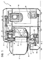
- Figure 1 shows a kneading machine for food products, particularly flour mixtures, comprising a fixed support structure 1 including a base 40 on which a kneading bowl 2 is supported for rotation about an axis B.
- the means for rotating the kneading bowl are contained in the base and include an electric motor 19 which - by means of a pulley 20 and V-belts 21 - rotates a pulley 22 fast with a toothed pinion 23 supported by a structure 5 anchored to the base of the kneader.
- the pinion 23 rotates a gear 24 keyed to a shaft 4 carrying a support flange 6 at its upper end, to which the kneading bowl 2 is anchored by means of screws.
- the fixed structure 1 of the machine also includes a head 41 which projects over the kneading bowl 2.
- the head 41 supports, for rotation about a vertical axis A, a shaft 13 carrying at its lower end a kneading tool 3 which, in the example illustrated, is of the spiral type.
- the kneading tool 3 is rotated about the axis A by an electric motor 18 and a transmission comprising a pulley 17 fixed to the driving shaft, a pulley 15 keyed to the shaft 13, and a series of V-belts 16 which engage the pulleys.
- the head 41 also supports, for rotation about the vertical axis C, a shaft 10 carrying at its lower end a counter member 8 which, in the example illustrated, is cylindrical in shape. The lower end of the cylinder 8 is spaced slightly from the bottom of the bowl.
- the counter member 8 is rotated about the axis C by a belt 12, a toothed belt in the example illustrated, which takes the drive from a pulley 14 mounted on the shaft 13 and transmits it to a pulley 11 mounted on the shaft 10.
- This shaft is supported rotatably by a hub 9 anchored to the head 41.
- the transmission ratio between the pulleys 11 and 14 is selected so as to achieve a predetermined rate of rotation of the element 8.
- the rate of rotation of the counter member 8 (which rotates in the same sense as the bowl and in the opposite sense to the kneading tool 3) is such that the peripheral velocity of the member 8 and the velocity of the bowl at the point indicated K are equal.
- This point corresponds to the intersection of the external surface of the counter member 8 (on the side facing towards the kneading tool 3) with the vertical plane containing the axes of rotation A, B and C.
- the presence of the counter member 9 causes the formation of an empty dough-free space X in the centre of the bowl, which ensures perfect aeration of the dough and keeps the dough at a low temperature.
- the shape of the rotating counter member 8 could be different from that illustrated.
Landscapes
- Engineering & Computer Science (AREA)
- Food Science & Technology (AREA)
- Life Sciences & Earth Sciences (AREA)
- Mechanical Engineering (AREA)
- Chemical & Material Sciences (AREA)
- Chemical Kinetics & Catalysis (AREA)
- Manufacturing And Processing Devices For Dough (AREA)
- Food-Manufacturing Devices (AREA)
- Preparation Of Clay, And Manufacture Of Mixtures Containing Clay Or Cement (AREA)
- Formation And Processing Of Food Products (AREA)
- Confectionery (AREA)
- Mixers Of The Rotary Stirring Type (AREA)
Abstract
Description
- The present invention relates to kneading machines for food products, particularly flour mixtures, of known type according to the pre-characterising portion of claim 1.
- Kneading machines for food products which have rotatable bowls and kneading tools rotatable about vertical axes have been known and used for some time. The kneading tool is usually spiral-shaped and machines of this type are commonly known as spiral kneading machines.
- Figure 2 and 3 show schematically and elevational view and a plan view of a conventional spiral kneading machine. In these drawings, the kneading bowl is indicated 26 and is rotatable about a vertical axis C, whilst the dough which is contained in the bowl and is rotated by the bowl itself is indicated 27. The rotation of the bowl gradually brings the various portions of the dough into correspondence with the
spiral kneading tool 25 which is supported for rotation about a vertical axis A spaced from the axis C. The senses of rotation of thebowl 26 and of thekneading tool 25 are indicated by the arrows. - The conventional spiral kneading machines illustrated in Figures 2 and 3 of the appended drawings have the disadvantage that they cause excessive heating of the dough with resulting physico-chemical changes in the dough which compromise the subsequent leavening and baking stages. The time required for the kneading is also relatively long and this, amongst other things, contributes to the increase in the degree of overheating of the product.
- In an attempt to resolve this problem, a kneading machine for food products of the type illustrated in Figures 4 and 5 of the appended drawings has been proposed in the past. This machine differs from a conventional machine in that it includes a
counter member 30 supported in a fixed position within therotatable bowl 26 at a certain distance from the axis of rotation C and adjacent the kneading tool 29. The presence of thecounter member 30 means that, in use, an empty dough-free space X is created in the central part of thebowl 26, which enables greater aeration of the dough and therefore a smaller increase in temperature. At the same time, themember 30 acts as a separator for detaching from thetool 25 any dough adhering thereto. - The known machine illustrated in Figures 4 and 5 enables the overheating of the dough to be avoided, but does not ensure a satisfactory degree of homogeneity of the product such as not to give rise to problems in the subsequent leavening stage. The reason for this lack of homogeneity consists of the fact that the dough detached from the
spiral kneading member 25 by thecounter member 30 is subjected to stretching which gives rise to unevenness in the dough. - In the conventional machine illustrated in Figures 2 and 3, the kneading time is of the order of 12-14 minutes and the increase in temperature is approximately 8-10°C. The known machine illustrated in Figures 4 and 5 has a kneading time of about 7-8 minutes and a temperature range of 5-6°C but, as already indicated, involves unevenness and stretching of the dough with a consequent lack of homogeneity.
- Figures 6 and 7 of the appended drawings illustrate another spiral kneading machine of known type produced and sold for some time by the Applicant, which differs from the conventional machine of Figures 2 and 3 in that a
column 35 is provided in the centre of the bowl, which is movable with the bowl and serves to detach the dough from thekneading tool 25. This system has considerable advantages, since the kneading time is very short (5 minutes); the temperature increase, however, is only slightly less than that of the conventional machine (7-8°C). The final homogeneity of the dough is considered satisfactory. - In the attempt to provide a remedy for the aforesaid drawbacks, FR-A-2546719 suggests to use a fixed cylindrical counter member with a flared base, disposed in a position analogous to that of the
counter member 30 in Figures 4 and 5, but this arrangement does not result wholly satisfactory. - Moreover DE-A-1757361 proposes making the counter member rotatable around its axis, and particularly rotatable in the same sense of rotation of the kneading bowl and in the opposite sense of the kneading tool.
- The object of the present invention is to produce a kneading machine of the type specified above which overcomes all the disadvantages of the solutions proposed up to now.
- In the order to achieve this object, the subject of the invention is a kneading machine of the type indicated at the beginning of the present description and having the features indicated in the characterising portion of claim 1.
- The counter member fulfils the function of a member for separating the dough from the kneading tool and at the same time creates a dough-free space in the centre of the bowl when the dough is rotated by the bowl. The temperature increase of the dough is thus limited. At the same time, since the counter member is rotatable, stretching of the dough is avoided so that a smooth dough is produced without unevenness.
- Tests carried out by the Applicant have shown that the dough produced by the machine according to the invention has a quite limited increase in temperature due to the kneading action compared with known systems. The degree of homogeneity achieved on completion of the kneading is much improved both as regards its smooth, soft appearance and as regards its behaviour during the subsequent leavening and baking stages. The quality of the final product is considerably better than with the known machine illustrated in Figures 4 and 5, since the dough which is in contact with the rotating counter member has the same velocity and is therefore accompanies by the rotating counter member.
- The smaller increase in temperature of the dough is due, as already indicated, to the creation of a central dough-free space within the bowl as a result of the present of the rotating counter member. The greater aeration of the dough, as well as the reduced temperature increase, causes and improved chemical oxidation-reduction effect which, in some cases, particularly in the confectionery industry, enables the obtention of products of better quality than those kneaded by known systems.
- Moreover, thanks to the fact that the velocity of the dough in the region between the kneading tool and the rotating counter member is identical to the peripheral velocity of that member, the dough is not subjected to stretching, so that perfect homogeneity of the produce is ensured.
- Further characteristics and advantages of the present invention will become clear from the detailed description which follows with reference to the appended drawings, provided by way of non-limiting example, in which:
- Figure 1 is a schematic elevational and sectional view of a kneading machine according to the present invention,
- Figures 2 and 3 show a first prior-art kneading machine,
- Figures 4 and 5 show a second prior-art kneading machine,
- Figures 6 and 7 show a third prior-art kneading machine, and
- Figures 8 and 9 show a schematic elevational and sectional view and a schematic plan view of the machine according to the invention.
- Figure 1 shows a kneading machine for food products, particularly flour mixtures, comprising a fixed support structure 1 including a
base 40 on which akneading bowl 2 is supported for rotation about an axis B. - The means for rotating the kneading bowl are contained in the base and include an
electric motor 19 which - by means of apulley 20 and V-belts 21 - rotates apulley 22 fast with atoothed pinion 23 supported by astructure 5 anchored to the base of the kneader. Thepinion 23 rotates agear 24 keyed to ashaft 4 carrying a support flange 6 at its upper end, to which the kneadingbowl 2 is anchored by means of screws. The fixed structure 1 of the machine also includes ahead 41 which projects over thekneading bowl 2. Thehead 41 supports, for rotation about a vertical axis A, ashaft 13 carrying at its lower end akneading tool 3 which, in the example illustrated, is of the spiral type. - The
kneading tool 3 is rotated about the axis A by anelectric motor 18 and a transmission comprising apulley 17 fixed to the driving shaft, apulley 15 keyed to theshaft 13, and a series of V-belts 16 which engage the pulleys. Thehead 41 also supports, for rotation about the vertical axis C, ashaft 10 carrying at its lower end a counter member 8 which, in the example illustrated, is cylindrical in shape. The lower end of the cylinder 8 is spaced slightly from the bottom of the bowl. The counter member 8 is rotated about the axis C by abelt 12, a toothed belt in the example illustrated, which takes the drive from apulley 14 mounted on theshaft 13 and transmits it to a pulley 11 mounted on theshaft 10. This shaft is supported rotatably by ahub 9 anchored to thehead 41. The transmission ratio between thepulleys 11 and 14 is selected so as to achieve a predetermined rate of rotation of the element 8. - With reference to Figures 8 and 9, the rate of rotation of the counter member 8 (which rotates in the same sense as the bowl and in the opposite sense to the kneading tool 3) is such that the peripheral velocity of the member 8 and the velocity of the bowl at the point indicated K are equal. This point corresponds to the intersection of the external surface of the counter member 8 (on the side facing towards the kneading tool 3) with the vertical plane containing the axes of rotation A, B and C. By virtue of this characteristic, the velocity of the dough in the region between the
kneading tool 3 and the rotating counter member 8 is identical to the peripheral velocity of that member. The dough is thus not subjected to stretching, so that perfect homogeneity of the produce is ensured. - As already indicated in the introduction to the present description, in use, the presence of the
counter member 9 causes the formation of an empty dough-free space X in the centre of the bowl, which ensures perfect aeration of the dough and keeps the dough at a low temperature. - Tests carried out by the Applicant have shown that the machine according to the invention causes an increase in the temperature of the dough of the order of 4-5°C. At the same time, the time necessary to produce the dough is relatively short (approximately 7 minutes).
- Naturally, the principle of the invention remaining the same, the forms of embodiment and details of construction may be varied widely with respect to those described and illustrated purely by way of example.
- For example, the shape of the rotating counter member 8 could be different from that illustrated.
Claims (2)
- A kneading machine for food products, particularly flour mixtures, comprising:
a kneading bowl (2) which is rotatable about a vertical axis (B),
a kneading tool (3) which is rotatable within the kneading bowl (2) about a vertical axis (A) spaced from the axis of rotation of the bowl (B), and
a counter member (8) supported within the bowl (2) and separate therefrom, for creating a dough-free space in the centre of the bowl when the dough is rotated by the bowl (2), said counter member (8) being rotatable about a vertical axis (C) coplanar with, and in a position intermediate, the axes of rotation (A, B) of the kneading tool (3) and of the kneading bowl (2), and
means for rotating the counter member (8) in the opposite sense to the sense of rotation of the kneading tool (3) and in the same sense as the sense of rotation of the kneading bowl (2),
characterised in that the peripheral velocity of the counter member (8) is equal to the peripheral velocity of the bowl (2) in correspondence with the part of the counter member which is furthest from the axis of rotation of the bowl (B). - A kneading machine according to Claim 1, characterised in that means are provided for rotating the bowl (2) and the tool (3) independently, and in that means are provided for transmitting the drive between the tool (3) and the counter member (8).
Priority Applications (1)
| Application Number | Priority Date | Filing Date | Title |
|---|---|---|---|
| AT88830456T ATE85195T1 (en) | 1987-11-03 | 1988-10-28 | KNEADER FOR FOOD. |
Applications Claiming Priority (2)
| Application Number | Priority Date | Filing Date | Title |
|---|---|---|---|
| IT8767933A IT1211456B (en) | 1987-11-03 | 1987-11-03 | MIXER MACHINE FOR FOOD PRODUCTS |
| IT6793387 | 1987-11-03 |
Publications (2)
| Publication Number | Publication Date |
|---|---|
| EP0315599A1 EP0315599A1 (en) | 1989-05-10 |
| EP0315599B1 true EP0315599B1 (en) | 1993-02-03 |
Family
ID=11306473
Family Applications (1)
| Application Number | Title | Priority Date | Filing Date |
|---|---|---|---|
| EP88830456A Expired - Lifetime EP0315599B1 (en) | 1987-11-03 | 1988-10-28 | A kneading machine for food products |
Country Status (5)
| Country | Link |
|---|---|
| EP (1) | EP0315599B1 (en) |
| AT (1) | ATE85195T1 (en) |
| DE (1) | DE3878161T2 (en) |
| ES (1) | ES2037279T3 (en) |
| IT (1) | IT1211456B (en) |
Families Citing this family (6)
| Publication number | Priority date | Publication date | Assignee | Title |
|---|---|---|---|---|
| ES2037574B1 (en) * | 1990-11-08 | 1994-01-16 | Sanchez Lopez Antonio | PASTRY MASS MIXER. |
| FR2710551B1 (en) * | 1993-09-27 | 1997-07-04 | Michel Loiselet | Mixing kneading device supplementing the action of the tool rotating concentrically on a horizontal, vertical or oblique line of kneader with non-rotating bowl. |
| AT311U1 (en) * | 1994-04-28 | 1995-08-25 | Schuhleitner Hubert | MIXER |
| ITTO20021020A1 (en) * | 2002-11-26 | 2004-05-27 | Sancassiano Spa | MIXER MACHINE FOR FOOD PASTA PARTICULARLY |
| US6883959B2 (en) * | 2002-12-23 | 2005-04-26 | Premark Feg L.L.C. | Power bowl lift, motor mount and tensioner for mixing machine |
| ITTO20100101U1 (en) * | 2010-06-01 | 2011-12-02 | Sancassiano Spa | FIXING SYSTEM OF A MIXER TOOL |
Family Cites Families (7)
| Publication number | Priority date | Publication date | Assignee | Title |
|---|---|---|---|---|
| NL68605C (en) * | 1900-01-01 | |||
| FR396464A (en) * | 1908-11-17 | 1909-04-13 | Leon Paulet Fils | Mechanical mixer |
| CH306332A (en) * | 1949-10-18 | 1955-04-15 | Kort August | Mixing, stirring, kneading and beating machine for mixable and kneadable materials, with a container and a cylindrical tool that can be set in rotation. |
| DE1283449B (en) * | 1962-10-19 | 1968-11-21 | Alfred Paul Kg | Kitchen machine |
| DE1757361B2 (en) * | 1968-04-30 | 1981-09-03 | Dierks & Söhne, 4500 Osnabrück | Machine for kneading dough |
| DE2153704B2 (en) * | 1971-10-28 | 1977-09-01 | Dough kneading machine | |
| FR2546719A1 (en) * | 1983-06-03 | 1984-12-07 | Fonderie Soc Gen De | Kneader with a kneading arm of vertical axis |
-
1987
- 1987-11-03 IT IT8767933A patent/IT1211456B/en active
-
1988
- 1988-10-28 DE DE8888830456T patent/DE3878161T2/en not_active Expired - Fee Related
- 1988-10-28 ES ES198888830456T patent/ES2037279T3/en not_active Expired - Lifetime
- 1988-10-28 AT AT88830456T patent/ATE85195T1/en not_active IP Right Cessation
- 1988-10-28 EP EP88830456A patent/EP0315599B1/en not_active Expired - Lifetime
Also Published As
| Publication number | Publication date |
|---|---|
| DE3878161D1 (en) | 1993-03-18 |
| ES2037279T3 (en) | 1993-06-16 |
| DE3878161T2 (en) | 1993-05-27 |
| EP0315599A1 (en) | 1989-05-10 |
| IT8767933A0 (en) | 1987-11-03 |
| IT1211456B (en) | 1989-10-26 |
| ATE85195T1 (en) | 1993-02-15 |
Similar Documents
| Publication | Publication Date | Title |
|---|---|---|
| EP0354190B1 (en) | Kneading machine for food products, particularly flour mixtures | |
| US4765746A (en) | Dough kneader | |
| US5393217A (en) | Noodle forming device | |
| EP0315599A1 (en) | A kneading machine for food products | |
| JPH07148074A (en) | Bread making device | |
| CN114684631A (en) | Clinker blanking device for cement production and processing | |
| CN210097606U (en) | Horizontal mixer of raw materials is used in peppery strip production | |
| JP3970919B1 (en) | Nida chaos and Nida and bread machine | |
| US5364183A (en) | Driving mechanism for kneading blade of a bread production device | |
| EP1474983B1 (en) | Improvements in and relating to bread makers | |
| SU991968A1 (en) | Machine for mixing components in production of bakery or confectionary products | |
| CN218428526U (en) | Bread processing is with even stripping and slicing device | |
| EP0551571B1 (en) | A kneading machine for food products | |
| KR0134664B1 (en) | Equipment for baking | |
| CN223027177U (en) | Stirring device for chocolate product processing | |
| CN215899436U (en) | Up-down transmission mechanism for cake machine | |
| EP1474979B1 (en) | Bread maker | |
| JP3180935B2 (en) | Gear device of bread maker | |
| JPH08290832A (en) | Garnish dishing machine | |
| CN112244048A (en) | A raw material processing device for cake processing | |
| JPS63153023A (en) | Electric bread maker | |
| KR910009445Y1 (en) | Domestic baking apparatus | |
| JP2949457B2 (en) | Mixing and stirring kneading cylinder mechanism | |
| KR920004670Y1 (en) | Dough Mixer for Powdered Food Production | |
| JPH04210018A (en) | Electric cooker and production of rotary cutter |
Legal Events
| Date | Code | Title | Description |
|---|---|---|---|
| PUAI | Public reference made under article 153(3) epc to a published international application that has entered the european phase |
Free format text: ORIGINAL CODE: 0009012 |
|
| AK | Designated contracting states |
Kind code of ref document: A1 Designated state(s): AT BE CH DE ES FR GB GR IT LI LU NL SE |
|
| 17P | Request for examination filed |
Effective date: 19890722 |
|
| 17Q | First examination report despatched |
Effective date: 19910611 |
|
| GRAA | (expected) grant |
Free format text: ORIGINAL CODE: 0009210 |
|
| AK | Designated contracting states |
Kind code of ref document: B1 Designated state(s): AT BE CH DE ES FR GB GR IT LI LU NL SE |
|
| PG25 | Lapsed in a contracting state [announced via postgrant information from national office to epo] |
Ref country code: SE Effective date: 19930203 Ref country code: NL Effective date: 19930203 Ref country code: LI Effective date: 19930203 Ref country code: GR Free format text: LAPSE BECAUSE OF FAILURE TO SUBMIT A TRANSLATION OF THE DESCRIPTION OR TO PAY THE FEE WITHIN THE PRESCRIBED TIME-LIMIT Effective date: 19930203 Ref country code: CH Effective date: 19930203 Ref country code: BE Effective date: 19930203 Ref country code: AT Effective date: 19930203 |
|
| REF | Corresponds to: |
Ref document number: 85195 Country of ref document: AT Date of ref document: 19930215 Kind code of ref document: T |
|
| ITF | It: translation for a ep patent filed | ||
| REF | Corresponds to: |
Ref document number: 3878161 Country of ref document: DE Date of ref document: 19930318 |
|
| REG | Reference to a national code |
Ref country code: CH Ref legal event code: PL |
|
| ET | Fr: translation filed | ||
| REG | Reference to a national code |
Ref country code: ES Ref legal event code: FG2A Ref document number: 2037279 Country of ref document: ES Kind code of ref document: T3 |
|
| NLV1 | Nl: lapsed or annulled due to failure to fulfill the requirements of art. 29p and 29m of the patents act | ||
| PGFP | Annual fee paid to national office [announced via postgrant information from national office to epo] |
Ref country code: ES Payment date: 19931007 Year of fee payment: 6 |
|
| PG25 | Lapsed in a contracting state [announced via postgrant information from national office to epo] |
Ref country code: GB Effective date: 19931028 |
|
| PG25 | Lapsed in a contracting state [announced via postgrant information from national office to epo] |
Ref country code: LU Free format text: LAPSE BECAUSE OF NON-PAYMENT OF DUE FEES Effective date: 19931031 |
|
| PLBE | No opposition filed within time limit |
Free format text: ORIGINAL CODE: 0009261 |
|
| STAA | Information on the status of an ep patent application or granted ep patent |
Free format text: STATUS: NO OPPOSITION FILED WITHIN TIME LIMIT |
|
| 26N | No opposition filed | ||
| GBPC | Gb: european patent ceased through non-payment of renewal fee |
Effective date: 19931028 |
|
| PG25 | Lapsed in a contracting state [announced via postgrant information from national office to epo] |
Ref country code: ES Free format text: LAPSE BECAUSE OF THE APPLICANT RENOUNCES Effective date: 19941029 |
|
| REG | Reference to a national code |
Ref country code: ES Ref legal event code: FD2A Effective date: 20001009 |
|
| PGFP | Annual fee paid to national office [announced via postgrant information from national office to epo] |
Ref country code: DE Payment date: 20020918 Year of fee payment: 15 |
|
| PGFP | Annual fee paid to national office [announced via postgrant information from national office to epo] |
Ref country code: FR Payment date: 20021011 Year of fee payment: 15 |
|
| PG25 | Lapsed in a contracting state [announced via postgrant information from national office to epo] |
Ref country code: DE Free format text: LAPSE BECAUSE OF NON-PAYMENT OF DUE FEES Effective date: 20040501 |
|
| PG25 | Lapsed in a contracting state [announced via postgrant information from national office to epo] |
Ref country code: FR Free format text: LAPSE BECAUSE OF NON-PAYMENT OF DUE FEES Effective date: 20040630 |
|
| REG | Reference to a national code |
Ref country code: FR Ref legal event code: ST |
|
| PG25 | Lapsed in a contracting state [announced via postgrant information from national office to epo] |
Ref country code: IT Free format text: LAPSE BECAUSE OF NON-PAYMENT OF DUE FEES;WARNING: LAPSES OF ITALIAN PATENTS WITH EFFECTIVE DATE BEFORE 2007 MAY HAVE OCCURRED AT ANY TIME BEFORE 2007. THE CORRECT EFFECTIVE DATE MAY BE DIFFERENT FROM THE ONE RECORDED. Effective date: 20051028 |