EP0314364B1 - Services connections for work stations within containment cells - Google Patents
Services connections for work stations within containment cells Download PDFInfo
- Publication number
- EP0314364B1 EP0314364B1 EP88309737A EP88309737A EP0314364B1 EP 0314364 B1 EP0314364 B1 EP 0314364B1 EP 88309737 A EP88309737 A EP 88309737A EP 88309737 A EP88309737 A EP 88309737A EP 0314364 B1 EP0314364 B1 EP 0314364B1
- Authority
- EP
- European Patent Office
- Prior art keywords
- cartridge
- throughbore
- sealing means
- tool
- assembly
- Prior art date
- Legal status (The legal status is an assumption and is not a legal conclusion. Google has not performed a legal analysis and makes no representation as to the accuracy of the status listed.)
- Expired - Lifetime
Links
- 238000007789 sealing Methods 0.000 claims description 17
- 238000006073 displacement reaction Methods 0.000 claims description 5
- 238000003780 insertion Methods 0.000 claims description 5
- 230000037431 insertion Effects 0.000 claims description 3
- 230000008878 coupling Effects 0.000 claims description 2
- 238000010168 coupling process Methods 0.000 claims description 2
- 238000005859 coupling reaction Methods 0.000 claims description 2
- 238000002955 isolation Methods 0.000 claims description 2
- 210000004027 cell Anatomy 0.000 description 24
- 230000007246 mechanism Effects 0.000 description 6
- 239000012530 fluid Substances 0.000 description 3
- 238000000034 method Methods 0.000 description 3
- 239000004020 conductor Substances 0.000 description 2
- 238000010276 construction Methods 0.000 description 2
- 230000000994 depressogenic effect Effects 0.000 description 2
- 239000013521 mastic Substances 0.000 description 2
- 230000002093 peripheral effect Effects 0.000 description 2
- 230000005855 radiation Effects 0.000 description 2
- 206010073306 Exposure to radiation Diseases 0.000 description 1
- 229910000831 Steel Inorganic materials 0.000 description 1
- 230000009471 action Effects 0.000 description 1
- 230000000712 assembly Effects 0.000 description 1
- 238000000429 assembly Methods 0.000 description 1
- 210000002421 cell wall Anatomy 0.000 description 1
- 230000008859 change Effects 0.000 description 1
- 150000001875 compounds Chemical class 0.000 description 1
- 239000000356 contaminant Substances 0.000 description 1
- 239000007788 liquid Substances 0.000 description 1
- 239000000463 material Substances 0.000 description 1
- 239000003758 nuclear fuel Substances 0.000 description 1
- 230000037361 pathway Effects 0.000 description 1
- 238000004382 potting Methods 0.000 description 1
- 238000007142 ring opening reaction Methods 0.000 description 1
- 239000002904 solvent Substances 0.000 description 1
- 125000006850 spacer group Chemical group 0.000 description 1
- 239000010959 steel Substances 0.000 description 1
- 238000003466 welding Methods 0.000 description 1
Images



Classifications
-
- G—PHYSICS
- G21—NUCLEAR PHYSICS; NUCLEAR ENGINEERING
- G21F—PROTECTION AGAINST X-RADIATION, GAMMA RADIATION, CORPUSCULAR RADIATION OR PARTICLE BOMBARDMENT; TREATING RADIOACTIVELY CONTAMINATED MATERIAL; DECONTAMINATION ARRANGEMENTS THEREFOR
- G21F7/00—Shielded cells or rooms
- G21F7/005—Shielded passages through walls; Locks; Transferring devices between rooms
-
- Y—GENERAL TAGGING OF NEW TECHNOLOGICAL DEVELOPMENTS; GENERAL TAGGING OF CROSS-SECTIONAL TECHNOLOGIES SPANNING OVER SEVERAL SECTIONS OF THE IPC; TECHNICAL SUBJECTS COVERED BY FORMER USPC CROSS-REFERENCE ART COLLECTIONS [XRACs] AND DIGESTS
- Y10—TECHNICAL SUBJECTS COVERED BY FORMER USPC
- Y10T—TECHNICAL SUBJECTS COVERED BY FORMER US CLASSIFICATION
- Y10T29/00—Metal working
- Y10T29/53—Means to assemble or disassemble
- Y10T29/531—Nuclear device
-
- Y—GENERAL TAGGING OF NEW TECHNOLOGICAL DEVELOPMENTS; GENERAL TAGGING OF CROSS-SECTIONAL TECHNOLOGIES SPANNING OVER SEVERAL SECTIONS OF THE IPC; TECHNICAL SUBJECTS COVERED BY FORMER USPC CROSS-REFERENCE ART COLLECTIONS [XRACs] AND DIGESTS
- Y10—TECHNICAL SUBJECTS COVERED BY FORMER USPC
- Y10T—TECHNICAL SUBJECTS COVERED BY FORMER US CLASSIFICATION
- Y10T29/00—Metal working
- Y10T29/53—Means to assemble or disassemble
- Y10T29/53274—Means to disassemble electrical device
- Y10T29/53283—Means comprising hand-manipulatable implement
Definitions
- This invention relates to the provision of services, such as electrical, hydraulic, pneumatic and other supplies, to workstations in order to support various working operations to be carried out.
- services connection assemblies comprising a cartridge having connectors at opposite ends for coupling with service supply lines, such cartridge co-operating with a unit in a throughbore of which the cartridge is disposed sealingly but slidably so as to be withdrawable from the unit on release of releasable means by which the position of the cartridge in the throughbore is normally fixed.
- a cartridge replacement means in the nature of a carrier which is attachable at opposite ends, on the one hand, to a cartridge to be replaced and, on the other hand, to the cartridge to replace it.
- this carrier By arranging that this carrier, from one end to the other, is of a size capable of maintaining the seal in the throughbore, it can be pushed through the throughbore so as to bring about replacement without loss of the seal.
- detachment of the carrier, with the replaced cartridge is then carried out but a consequence of this arrangement is that not only the replaced cartridge but also the carrier are now present in the controlled environment from which removal will be desirable.
- the invention is characterised by the throughbore having constant cross-sectional area, elongation of the throughbore to a length exceeding its cross-section dimensions and sufficient for one said cartridge following another said cartridge nose to tail to be displaceable through the throughbore without loss of seal in bringing the one said cartridge into position in place of the other said cartridge by operation of the cartridge replacement means, the one said cartridge and the another said cartridge each being of cylindrical form of a diameter such as to be a close sliding fit in the throughbore, and a plurality of sealing means carried by each cartridge for maintaining the isolation of the controlled environment from the surroundings, said sealing means being located on the cartridge within a spacing less than the length of the throughbore and at positions such that adjacent said sealing means of the one said cartridge and the another said cartridge are at a distance less than the length of the throughbore whereby during displacement of the another said cartridge into the controlled environment by the one said cartridge from the throughbore never less than two said sealing means are engaged with the surface of the throughbore.
- the illustrated example is for a containment cell as used in the nuclear and pharmaceutical industries where the work area is in controlled environment required to be isolated from its surroundings and work operations are carried out within that environment under manual control either via glove fittings, as in glove boxes, or via master-slave manipulators.
- the cell in this instance is a shielded containment cell for the post irradiation examination of nuclear fuel materials but it is to be understood that the ambit of the invention is not restricted to this specific application.
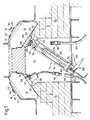
- the boundary of the base of a containment cell is defined by a liner 10 beneath which there is provided a man-access tunnel 12 which is shielded by blocks 14 of lead shielding and blocks 16 of steel shielding to protect personnel from exposure to radiation levels prevailing within the cell, ie above the liner 10.
- the tunnel houses a wide range of services supply lines, eg electrical power at different ratings, hydraulics, pneumatics, liquid supplies (eg solvents) at different pressures, vacuum supplies, instrument connections etc.
- the cell has a series of in-cell workstations disposed at intervals lengthwise of the tunnel and each workstation is provided with a services-supply unit 18 (two are shown in Figure 1, one on each side of the tunnel) by means of which various services are brought into the cell, the services being selected according to the needs of each particular workstation (which needs may change from time to time).
- a services-supply unit 18 two are shown in Figure 1, one on each side of the tunnel
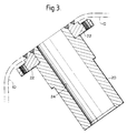
- a typical services-supply unit 18 may present twelve services connection points. As shown in Figures 1-3, each unit 18 comprises a number of sleeves 20 connected, as by welding for example, to a common mounting plate 22 which is itself secured to the liner so that the throughbores 24 in the sleeves open into the interior of the cell. Each throughbore 24 is elongated, with constant cross-sectional area, and serves to receive a respective services-connection cartridge 26, examples of which are shown in Figure 1 and are shown in greater detail in Figures 4 and 5. It will also be noted that the length of each throughbore is such as to exceed the maximum cross-sectional dimension.
- the cartridge 26 shown in Figures 4 and 4A is intended for use with a fluid supply such as compressed air of hydraulic fluid whilst that of Figure 5 is intended for electrical power supply.
- a fluid supply such as compressed air of hydraulic fluid
- Figure 5 is intended for electrical power supply.
- a wide variety of cartridges will in general be employed according to the range of service required but, in each instance, the cartridges will have certain features in common so that any one of the different types of cartridges available can be inserted into any one of the sleeves 20 of each services-supply unit 18.
- each cartridge 26 comprises a generally cylindrical body 28 of a diameter which is a close sliding fit in the throughbores 24 and each body is provided with peripheral grooves receiving O-ring seals 32 in order to make sealing but slidable engagement with the throughbores 24 on insertion into the sleeves 20, the maximum spacing between the seals being less than the length of the throughbores.
- each body 28 is provided with an inward flange 34 which, at diametrically opposite positions around its circumference, is interrupted by slots 36, 38 ( Figure 4A) one of which is wider, in the circumferential direction, than the other.
- Connectors 40, 42 are associated with the in-cell and out-of-cell ends respectively of each cartridge 26 for quick-release connection with in-cell connectors 44 and out-of-cell connectors 46 (not shown in Figure 5).
- each cartridge Adjacent to the out-of-cell end, each cartridge is formed with a latch keeper 50 in the form of a transverse bore in the outer cylindrical wall of the body 28.
- Figure 1 illustrates cartridges 26 located in their normal operative positions relative to the units 18, ie with the connectors 40 accessible from the interior of the cell and with the connectors 42 accessible from within the man-access tunnel beneath the cell.
- supply lines eg cable 52/hose 54
- the out-of-cell connectors 42 will be connected to the connectors 40.
- the seals 32 on the cartridges make sealing contact with the walls of the throughbores 24 so that any desired conditions prevailing within the cell, eg sub-atmospheric pressure, are maintained.
- each cartridge 26 When properly located, each cartridge 26 is held axially and rotatably captive in the unit 18 by a latching mechanism 56 associated with each sleeve 20.
- the latching mechanism comprises a lever 58 mounted pivotally on a pin 60 for movement, in a plane normal to the axis of the sleeve 20, between a latching position (see Figure 8) in which a latch projection 62 extends radially inwardly of the throughbore (but at a position external to the bore in the illustrated embodiment) for engagement in the keeper hole 50 of a cartridge and a releasing position (see Figure 10) in which the projection is retracted radially out of engagement with the cartridge.
- the latch lever 58 is urged to its latching position by a torsion coil spring 64 (see Figure 6) and a stop 66 limits pivoting of the lever in the latching direction.
- the lever 58 also carries a cam follower 68 and each sleeve 20 is provided with a pair of diametrally-related headed pins 70 for co-operation with a cartridge-insertion tool 72.
- the tool 72 is provided for loading replacement cartridges into the sleeves 20 when, for instance, one or more of the service supplies to a workstation is to be changed.
- the tool allows replacement to be carried out without breaking the cell containment.
- the tool comprises a cartridge-receiving section or cage defined by a number of parallel and equiangularly spaced guide rods 74 (four are shown) extending from a mounting plate 76 and terminating at a ring 78, the diameter of the ring 78 and the diametral spacing of the rods 74 being such that a cartridge can be loaded as a fairly close sliding fit into the tool via the ring opening.
- Figures 1 and 6 illustrate a cartridge 28 loaded into the tool.
- the tool includes a piston member 80 formed with equiangularly-spaced, peripheral recesses 82 which register with the guide rods 74 so that the piston can travel, without rotating, along the cartridge-receiving cage between the retracted position shown in Figures 1 and 6 and an extended position (not shown) in which the leading face of the piston 80 abuts stops 84 (see Figure 6) located adjacent the ring 78. Displacement of the piston 80 towards the ring 78 can be effected by any suitable means.
- the tool 72 incorporates a jacking-type mechanism of the kind well-known for use in mastic applicator guns.
- the tool 72 differs from a conventional mastic gun in two important respects, ie the construction of the piston 80 and the ring 78.
- the piston 80 comprises a main body 98 formed with a diametral recess 100 accommodating a locating member 102 which is slidable axially of the piston 80 under the control of pins 104 and springs 106, the springs 106 normally biasing the locating member 102 to a projecting position as shown in Figure 6 where it is proud of the leading face 108 of the piston.
- the locating member 102 can be depressed into the recess 100, against the biassing of the springs 106, until it is no longer proud of the leading face.
- the width of the member 102 corresponds to the circumferential extent of the slot 38 in the cartridge flange 34 ( Figure 4A) and is greater than that of the slot 36.
- the member 102 is formed with a pair of strategically located cut-outs 110 so that it can register with both slots 36, 38 of the cartridge when the cartridge is loaded into the tool with its out-of-cell end abutting the piston 80.
- the member 102 consequently serves as a means for securing a predetermined angular orientation of the cartridge with respect to the tool and, as will become apparent, with respect to the sleeve 20 in which the cartridge is to be installed.
- the ring 78 carries a part-annular bracket 112 whose axis of curvature generally coincides with the central axis of the cartridge-receiving cage.
- the bracket 112 has a pair of diametrally-opposite slots 114, 116 of generally keyhole-configuration except that the enlarged portion of slot 114 is truncated at one end of the bracket.
- the slots 114, 116 are arranged for registration with the headed pins 70 on the sleeves 20 in the manner of a bayonet-fitting.
- the bracket 112 can be displaced towards the out-of-cell end of the sleeve 20 so that the heads of the pins 70 pass through the enlarged portions of the slots 114, 116 (see Figure 9) until the heads are clear of the bracket thus allowing the tool to be rotated (clockwise as seen in Figures 9 and 10) to trap the pins 70 within the narrower sections of the slots 114, 116 and thereby hold the tool axially captive to the sleeve. Rotation of the tool is accompanied by corresponding rotation of the cartridge by virtue of engagement of the locating member 102 in slots 36, 38.
- the ring 78 also carries a cam 118 which, when the tool 72 is initially registered with the pins 70 as in Figure 9, is brought into close proximity with the cam follower 68. As the tool is rotated to the position shown in Figure 10, the cam 118 lifts the follower 68 and shifts the latch lever 58 to its releasing position. Thus, the action of correctly registering the tool with the sleeve automatically delatches the cartridge which currently occupies the sleeve. With the tool correctly registered, insertion of a replacement cartridge can now proceed (assuming connectors 42, 44 have been disconnected from their supply lines). This is effected by operating the handle assembly 88 to displace the piston 80 and hence to feed forwardly the replacement cartridge towards the sleeve 20.
- the dimensioning of the cartridges 26 relative to the tool and the sleeve may be such that, when the tool is registered with the sleeve and the replacement cartridge is fully loaded in the tool, the leading end of the replacement cartridge abuts the trailing end of the cartridge to be replaced, so that they are in nose to tail relationship.
- the two cartridges travel in tandem axially of the sleeve 20 with the flange 34 of the leading cartridge seating on a shoulder or rebate 120 (see Figure 4, 5 and 6) of the trailing cartridge.
- the trailing cartridge enters the sleeve 20 while the leading cartridge is pushed further into the cell.
- the leading cartridge will eventually be displaced out of the sleeve so, to prevent damage, it may be supported within the cell by means of the master-slave manipulator associated with the workstation at which the replacement operation is being carried out.
- the containment conditions are maintained, ie at all times the throughbore is plugged against loss of containment environment and radiation shine-through by the leading cartridge and/or the trailing cartridge and sealing is maintained by the seals which are spaced with sufficient closeness to the cartridge ends that between adjacent seals on the leading and trailing cartridges the spacing is exceeded by the length of the throughbore.
- a seal is at all times maintained by at least two of the O-ring seals 32, whether they be on one or other or both of the cartridges.
- the tool is reverse rotated to the position shown in Figure 9 without, it will be noted, rotating the cartridge since the latter is now disengaged from the locating member 102.
- the cam 118 allows the latch to return and latch the replacement cartridge to the sleeve.
- the tool 72 may then be withdrawn and reloaded, after returning the piston 80 to its fully retracted position.
- the replaced cartridge will be located within the cell and may be posted out of the cell for disposal or re-use.
- the internal constructions of the cartridges may vary considerably according to their particular functions.
- that of Figure 4 comprises an internal stepped bore 120 interconnecting the connectors 40, 42 and accommodating a shielding plug 122 provided with helically extending channels 124 (one only shown) providing fluid flow paths while protecting against radiation shine-through.
- the cartridge of Figure 5 includes a number of insulated electrical conductors 130 (one only shown) providing electrical continuity between an in-cell electrical socket-type adaptor 40 and an out-of-cell plug-type electrical adaptor 42.
- the conductors 130 are arranged to follow a meandering pathway through the cartridge, by means of an annular spacer 132 having conductor-receiving slots around its periphary, and are embedded within a suitable potting compound 134 filling the interior of the cartridge.
- the out-of-cell connector 42 is united with the cartridge by a length of the sheathed cable - it will be understood that prior to effecting replacement of this type of cartridge, the connector 42 will first of all be cut-off by severing the cable so that the cartridges can be brought into abutment without hindrance.
Landscapes
- Physics & Mathematics (AREA)
- Engineering & Computer Science (AREA)
- General Engineering & Computer Science (AREA)
- High Energy & Nuclear Physics (AREA)
- Quick-Acting Or Multi-Walled Pipe Joints (AREA)
Description
- This invention relates to the provision of services, such as electrical, hydraulic, pneumatic and other supplies, to workstations in order to support various working operations to be carried out.
- Where the workstations are situated in a controlled environment to be maintained isolated from its surroundings, the entry of services supplies into that environment needs to be sealed. Already known for this purpose are services connection assemblies comprising a cartridge having connectors at opposite ends for coupling with service supply lines, such cartridge co-operating with a unit in a throughbore of which the cartridge is disposed sealingly but slidably so as to be withdrawable from the unit on release of releasable means by which the position of the cartridge in the throughbore is normally fixed.
- In an article entitled 'Two-piece replaceable gastight utility plugs for the walls of hot cells' published in Kerntechnik, vol 7, no. 12, December 1965, there is described a two-part services connection plug for hot cells. The plug is located in a throughbore in a cell wall and comprises a head part and a main part, each of which is sealed to the throughbore by one seal. To replace the plug the main part is withdrawn into the operational side of the cell, leaving the contaminated head part in the throughbore. A complete new plug is then pushed into the throughbore to eject the original head part into the cell. However, since only one seal is present in the throughbore until the new plug is almost fully home there is a risk of contaminant leakage from the cell to the operational side.
- It may be required that one type of service can be substituted for another, hence that an exchange of cartridges can be easily carried out. For facilitating such exchange, it is known already to use a cartridge replacement means in the nature of a carrier which is attachable at opposite ends, on the one hand, to a cartridge to be replaced and, on the other hand, to the cartridge to replace it. By arranging that this carrier, from one end to the other, is of a size capable of maintaining the seal in the throughbore, it can be pushed through the throughbore so as to bring about replacement without loss of the seal. For completion of the replacement operation, detachment of the carrier, with the replaced cartridge, is then carried out but a consequence of this arrangement is that not only the replaced cartridge but also the carrier are now present in the controlled environment from which removal will be desirable.
- With controlled environments within containment cells as used in the nuclear industry, any object becoming exposed to such an environment generally has to be treated as contaminated and therefore subject on removal to special precaitions in handling and disposal. There is therefore an incentive to minimise the number and bulk of objects that call for removal from such an environment.
- The invention is characterised by the throughbore having constant cross-sectional area, elongation of the throughbore to a length exceeding its cross-section dimensions and sufficient for one said cartridge following another said cartridge nose to tail to be displaceable through the throughbore without loss of seal in bringing the one said cartridge into position in place of the other said cartridge by operation of the cartridge replacement means, the one said cartridge and the another said cartridge each being of cylindrical form of a diameter such as to be a close sliding fit in the throughbore, and a plurality of sealing means carried by each cartridge for maintaining the isolation of the controlled environment from the surroundings, said sealing means being located on the cartridge within a spacing less than the length of the throughbore and at positions such that adjacent said sealing means of the one said cartridge and the another said cartridge are at a distance less than the length of the throughbore whereby during displacement of the another said cartridge into the controlled environment by the one said cartridge from the throughbore never less than two said sealing means are engaged with the surface of the throughbore.
- By means of the invention, no further objects are introduced into the controlled environment than have been already exposed thereto, that is to say, the replaced cartridge, and therefore the task of later removal of introduced objects is simplified and the overall operation of exchanging cartridges is made easier.
- The invention will now be described by way of example only with reference to the accompanying drawings, in which:
- Figure 1 is a sectional view showing part only of a containment cell and a shielded man-access tunnel beneath the cell, the view also illustrating a cartridge-changing tool in position;
- Figure 2 is a perspective view of part of a services-supply unit for reception of services-connection cartridges (latch mechanisms omitted);
- Figure 3 is a sectional view of one of the sleeves of the manifold unit, the section being taken in the direction 3-3 in Figure 2.
- Figure 4 is a half-sectioned side view of one form of services-connection cartridge and Figure 4A is an end view of the cartridge;
- Figure 5 is a similar view to that of Figure 4 of another form of services-connection cartridge;
- Figure 6 is a side view, partly-sectioned, showing a cartridge-insertion tool in alignment with a cartridge-receiving sleeve of the manifold unit;
- Figure 7 is a sectional view in the direction 7-7 in Figure 6 of the piston of the tool;
- Figure 8 is an end view in the direction 8-8 in Figure 6; and
- Figures 9 and 10 are sectional views in the direction 9-9 Figure 6 showing the manner in which the tool operates a latch associated with the cartridge-receiving sleeve.
- The illustrated example is for a containment cell as used in the nuclear and pharmaceutical industries where the work area is in controlled environment required to be isolated from its surroundings and work operations are carried out within that environment under manual control either via glove fittings, as in glove boxes, or via master-slave manipulators.
- Specifically the cell in this instance is a shielded containment cell for the post irradiation examination of nuclear fuel materials but it is to be understood that the ambit of the invention is not restricted to this specific application.
- Referring now to Figures 1-3, the boundary of the base of a containment cell is defined by a
liner 10 beneath which there is provided a man-access tunnel 12 which is shielded byblocks 14 of lead shielding andblocks 16 of steel shielding to protect personnel from exposure to radiation levels prevailing within the cell, ie above theliner 10. The tunnel houses a wide range of services supply lines, eg electrical power at different ratings, hydraulics, pneumatics, liquid supplies (eg solvents) at different pressures, vacuum supplies, instrument connections etc. The cell has a series of in-cell workstations disposed at intervals lengthwise of the tunnel and each workstation is provided with a services-supply unit 18 (two are shown in Figure 1, one on each side of the tunnel) by means of which various services are brought into the cell, the services being selected according to the needs of each particular workstation (which needs may change from time to time). - A typical services-
supply unit 18 may present twelve services connection points. As shown in Figures 1-3, eachunit 18 comprises a number ofsleeves 20 connected, as by welding for example, to acommon mounting plate 22 which is itself secured to the liner so that thethroughbores 24 in the sleeves open into the interior of the cell. Eachthroughbore 24 is elongated, with constant cross-sectional area, and serves to receive a respective services-connection cartridge 26, examples of which are shown in Figure 1 and are shown in greater detail in Figures 4 and 5. It will also be noted that the length of each throughbore is such as to exceed the maximum cross-sectional dimension. - The
cartridge 26 shown in Figures 4 and 4A is intended for use with a fluid supply such as compressed air of hydraulic fluid whilst that of Figure 5 is intended for electrical power supply. A wide variety of cartridges will in general be employed according to the range of service required but, in each instance, the cartridges will have certain features in common so that any one of the different types of cartridges available can be inserted into any one of thesleeves 20 of each services-supply unit 18. Thus, irrespective of the particular service to be supplied, eachcartridge 26 comprises a generallycylindrical body 28 of a diameter which is a close sliding fit in thethroughbores 24 and each body is provided with peripheral grooves receiving O-ring seals 32 in order to make sealing but slidable engagement with thethroughbores 24 on insertion into thesleeves 20, the maximum spacing between the seals being less than the length of the throughbores. - At one end, the out-of-cell end, each
body 28 is provided with aninward flange 34 which, at diametrically opposite positions around its circumference, is interrupted byslots 36, 38 (Figure 4A) one of which is wider, in the circumferential direction, than the other.Connectors cartridge 26 for quick-release connection with in-cell connectors 44 and out-of-cell connectors 46 (not shown in Figure 5). Adjacent to the out-of-cell end, each cartridge is formed with alatch keeper 50 in the form of a transverse bore in the outer cylindrical wall of thebody 28. - Figure 1 illustrates
cartridges 26 located in their normal operative positions relative to theunits 18, ie with theconnectors 40 accessible from the interior of the cell and with theconnectors 42 accessible from within the man-access tunnel beneath the cell. In use, supply lines,eg cable 52/hose 54, will be connected to the out-of-cell connectors 42 and similar in-cell supply lines (not shown) will be connected to theconnectors 40. Theseals 32 on the cartridges make sealing contact with the walls of thethroughbores 24 so that any desired conditions prevailing within the cell, eg sub-atmospheric pressure, are maintained. - When properly located, each
cartridge 26 is held axially and rotatably captive in theunit 18 by alatching mechanism 56 associated with eachsleeve 20. As shown in Figure 6, 8, 9 and 10, the latching mechanism comprises alever 58 mounted pivotally on apin 60 for movement, in a plane normal to the axis of thesleeve 20, between a latching position (see Figure 8) in which alatch projection 62 extends radially inwardly of the throughbore (but at a position external to the bore in the illustrated embodiment) for engagement in thekeeper hole 50 of a cartridge and a releasing position (see Figure 10) in which the projection is retracted radially out of engagement with the cartridge. Thelatch lever 58 is urged to its latching position by a torsion coil spring 64 (see Figure 6) and astop 66 limits pivoting of the lever in the latching direction. Thelever 58 also carries acam follower 68 and eachsleeve 20 is provided with a pair of diametrally-related headedpins 70 for co-operation with a cartridge-insertion tool 72. - The
tool 72 is provided for loading replacement cartridges into thesleeves 20 when, for instance, one or more of the service supplies to a workstation is to be changed. The tool allows replacement to be carried out without breaking the cell containment. As shown in Figure 6, the tool comprises a cartridge-receiving section or cage defined by a number of parallel and equiangularly spaced guide rods 74 (four are shown) extending from amounting plate 76 and terminating at aring 78, the diameter of thering 78 and the diametral spacing of therods 74 being such that a cartridge can be loaded as a fairly close sliding fit into the tool via the ring opening. Figures 1 and 6 illustrate acartridge 28 loaded into the tool. - The tool includes a
piston member 80 formed with equiangularly-spaced,peripheral recesses 82 which register with theguide rods 74 so that the piston can travel, without rotating, along the cartridge-receiving cage between the retracted position shown in Figures 1 and 6 and an extended position (not shown) in which the leading face of thepiston 80 abuts stops 84 (see Figure 6) located adjacent thering 78. Displacement of thepiston 80 towards thering 78 can be effected by any suitable means. In the illustrated embodiment, thetool 72 incorporates a jacking-type mechanism of the kind well-known for use in mastic applicator guns. Repeated operation of thetrigger 86 of thehandle assembly 88 serves to shift adrive shaft 90 incrementally by means of acanted plate 92 so that thepiston 80, which is connected to one end of theshaft 90, is likewise displaced incrementally towards its extended position with consequent forward feeding of thecartridge 26 in a discharge direction. The jacking mechanism is purely conventional and further detailed description is therefore unnecessary except to note that, as in conventional mechanisms of this type, the drive is unidirectional and theshaft 90 can only be returned towards its starting position by releasing abrake plate 94 and pulling the shaft back. - The
tool 72 differs from a conventional mastic gun in two important respects, ie the construction of thepiston 80 and thering 78. Referring to Figures 6 and 7, thepiston 80 comprises amain body 98 formed with adiametral recess 100 accommodating a locatingmember 102 which is slidable axially of thepiston 80 under the control of pins 104 andsprings 106, thesprings 106 normally biasing the locatingmember 102 to a projecting position as shown in Figure 6 where it is proud of the leadingface 108 of the piston. In the circumstances to be described, the locatingmember 102 can be depressed into therecess 100, against the biassing of thesprings 106, until it is no longer proud of the leading face. The width of themember 102 corresponds to the circumferential extent of theslot 38 in the cartridge flange 34 (Figure 4A) and is greater than that of theslot 36. However, themember 102 is formed with a pair of strategically located cut-outs 110 so that it can register with bothslots piston 80. Themember 102 consequently serves as a means for securing a predetermined angular orientation of the cartridge with respect to the tool and, as will become apparent, with respect to thesleeve 20 in which the cartridge is to be installed. - The
ring 78 carries a part-annular bracket 112 whose axis of curvature generally coincides with the central axis of the cartridge-receiving cage. Thebracket 112 has a pair of diametrally-opposite slots slot 114 is truncated at one end of the bracket. Theslots sleeves 20 in the manner of a bayonet-fitting. Thus, provided thetool 72 is offered up to the sleeve in the correct orientation, thebracket 112 can be displaced towards the out-of-cell end of thesleeve 20 so that the heads of thepins 70 pass through the enlarged portions of theslots 114, 116 (see Figure 9) until the heads are clear of the bracket thus allowing the tool to be rotated (clockwise as seen in Figures 9 and 10) to trap thepins 70 within the narrower sections of theslots member 102 inslots - The
ring 78 also carries acam 118 which, when thetool 72 is initially registered with thepins 70 as in Figure 9, is brought into close proximity with thecam follower 68. As the tool is rotated to the position shown in Figure 10, thecam 118 lifts thefollower 68 and shifts thelatch lever 58 to its releasing position. Thus, the action of correctly registering the tool with the sleeve automatically delatches the cartridge which currently occupies the sleeve. With the tool correctly registered, insertion of a replacement cartridge can now proceed (assumingconnectors handle assembly 88 to displace thepiston 80 and hence to feed forwardly the replacement cartridge towards thesleeve 20. The dimensioning of thecartridges 26 relative to the tool and the sleeve may be such that, when the tool is registered with the sleeve and the replacement cartridge is fully loaded in the tool, the leading end of the replacement cartridge abuts the trailing end of the cartridge to be replaced, so that they are in nose to tail relationship. - As the
piston 80 is displaced along theguide rods 74, the two cartridges travel in tandem axially of thesleeve 20 with theflange 34 of the leading cartridge seating on a shoulder or rebate 120 (see Figure 4, 5 and 6) of the trailing cartridge. Eventually, the trailing cartridge enters thesleeve 20 while the leading cartridge is pushed further into the cell. The leading cartridge will eventually be displaced out of the sleeve so, to prevent damage, it may be supported within the cell by means of the master-slave manipulator associated with the workstation at which the replacement operation is being carried out. During the replacement procedure, the containment conditions are maintained, ie at all times the throughbore is plugged against loss of containment environment and radiation shine-through by the leading cartridge and/or the trailing cartridge and sealing is maintained by the seals which are spaced with sufficient closeness to the cartridge ends that between adjacent seals on the leading and trailing cartridges the spacing is exceeded by the length of the throughbore. Thus during the replacement procedure a seal is at all times maintained by at least two of the O-ring seals 32, whether they be on one or other or both of the cartridges. - As the
piston 80 travels along therods 74, it eventually reaches a position where the locatingmember 102 encounters thestop 84. The locating member is therefore arrested and, as the piston continues to move forward, it is caused to be retracted into therecess 100 so that when themain body 98 of the piston engages, and is arrested by, thestops 84, themember 102 is fully depressed and is disengaged from theslots keeper 50 of the cartridge is now aligned both axially and angularly with thelatch pin 68 when the latter is allowed to move into its latching position. - To complete the procedure, the tool is reverse rotated to the position shown in Figure 9 without, it will be noted, rotating the cartridge since the latter is now disengaged from the locating
member 102. Thecam 118 allows the latch to return and latch the replacement cartridge to the sleeve. Thetool 72 may then be withdrawn and reloaded, after returning thepiston 80 to its fully retracted position. The replaced cartridge will be located within the cell and may be posted out of the cell for disposal or re-use. - The internal constructions of the cartridges may vary considerably according to their particular functions. By way of example, that of Figure 4 comprises an internal stepped bore 120 interconnecting the
connectors shielding plug 122 provided with helically extending channels 124 (one only shown) providing fluid flow paths while protecting against radiation shine-through. The cartridge of Figure 5 includes a number of insulated electrical conductors 130 (one only shown) providing electrical continuity between an in-cell electrical socket-type adaptor 40 and an out-of-cell plug-typeelectrical adaptor 42. To provide protection against shine-through, theconductors 130 are arranged to follow a meandering pathway through the cartridge, by means of anannular spacer 132 having conductor-receiving slots around its periphary, and are embedded within asuitable potting compound 134 filling the interior of the cartridge. In this example, the out-of-cell connector 42 is united with the cartridge by a length of the sheathed cable - it will be understood that prior to effecting replacement of this type of cartridge, theconnector 42 will first of all be cut-off by severing the cable so that the cartridges can be brought into abutment without hindrance.
Claims (8)
- A services connection assembly by which to effect sealed entry of service supplies, such as electrical, hydraulic, pneumatic and other supplies, to a controlled environment to be maintained isolated from its surroundings, such assembly comprising a unit (20) having a throughbore (24) for communicating between the controlled environment and the surroundings, a cartridge (26) to be disposed sealingly but slidably in the throughbore (24) and having connectors (42, 44) at opposite ends for coupling with service supply lines, releasable means (56) for fixing the position of the cartridge (26) in the throughbore (24), and a cartridge replacement means (72) detachably engageable with the unit (20) externally of the controlled environment, characterised by the throughbore (24) having constant cross-sectional area, elongation of the throughbore (24) to a length exceeding its cross-sectional dimensions and sufficient for one said cartridge (26) following another said cartridge (26) nose to tail to be displaceable through the throughbore (24) without loss of the seal in bringing the one said cartridge (26) into position in place of the other said cartridge (26) by operation of the cartridge replacement means (72), the one said cartridge (26) and the another said cartridge (26) each being of cylindrical form of a diameter such as to be a close sliding fit in the throughbore (24), and a plurality of sealing means (32) carried by each cartridge (26) for maintaining the isolation of the controlled environment from the surroundings, said sealing means (32) being located on the cartridge (26) within a spacing less than the length of the throughbore (24) and at positions such that adjacent said sealing means (32) of the one said cartridge (26) and the another said cartridge (26) are at a distance less than the length of the throughbore (24) whereby during displacement of the another said cartridge (26) into the controlled environment by the one said cartridge (26) from the throughbore (24) never less than two said sealing means (32) are engaged with the surface of the throughbore (24).
- An assembly as claimed in Claim 1, wherein the sealing means (32) comprise two adjacent ring-shaped seals (32) at a nose end of the cartridge (26), and another ring-shaped seal (32) close to a trailing end of the cartridge (26).
- An assembly as claimed in Claim 1 or Claim 2, in which the releasable means for fixing the position of the cartridge in the throughbore is a latching means (56) and the cartridge replacement means is a manually operable tool (72) which, when engaged with the unit (20), is operable to release the latching means (56) in readiness for displacement of the cartridge (26) to be replaced.
- An assembly as claimed in Claim 3, in which the tool (72) is engageable with the unit (20) via interfitting elements (70, 114, 116) which are brought into and out of registry by rotation of the tool (72) relative to the unit (20).
- An assembly as claimed in Claim 4, in which the latching means (56) is released by rotation of the tool (72) in a direction which brings the interfitting elements (70, 114, 116) into registry, and in which the latching means (56) is engaged by rotation of the tool (72) to take interfitting elements (70, 114, 116) out of registry.
- An assembly as claimed in any one of the preceding Claims, in which the unit (20) is provided with a plurality of throughbores (24) each for removably receiving a cartridge (26).
- A services connection cartridge (26) for removable insertion into the throughbore (24) of a unit (20) of an assembly as claimed in any one of the preceding Claims, such cartridge (26) having at opposite ends thereof connectors (42, 44) for engagement with services supply lines, and sealing means (32) carried by the cartridge (26) around its external periphery for sealingly and slidably engaging the wall of the throughbore (24), characterised by the cartridge (26) being of cylindrical form, the interior of the cartridge (26) providing or incorporating means affording continuity of supply between said connectors (42, 44), a plurality of said sealing means (32) being located in the cartridge (26) within a length not exceeding the length of the throughbore (24) and at positions such that, with the cartridge (26) in nose to tail relationship with another such cartridge (26), the spacing between the sealing means (32) adjacent one another on the two cartridges (26) is also less than the length of the throughbore (24), whereby in carrying out a displacement of the two cartridges (26) through the throughbore (24) to replace the one by the other therein, never less than two of the sealing means (32) are sealingly engaged therewith.
- A cartridge as claimed in Claim 7, in which the sealing means (32) comprise two adjacent ring-shaped seals (32) at a nose end of the cartridge (26), and another ring-shaped seal (32) close to a trailing end of the cartridge (26).
Applications Claiming Priority (2)
| Application Number | Priority Date | Filing Date | Title |
|---|---|---|---|
| GB878725032A GB8725032D0 (en) | 1987-10-26 | 1987-10-26 | Services connections |
| GB8725032 | 1987-10-26 |
Publications (3)
| Publication Number | Publication Date |
|---|---|
| EP0314364A2 EP0314364A2 (en) | 1989-05-03 |
| EP0314364A3 EP0314364A3 (en) | 1990-01-24 |
| EP0314364B1 true EP0314364B1 (en) | 1993-12-08 |
Family
ID=10625889
Family Applications (1)
| Application Number | Title | Priority Date | Filing Date |
|---|---|---|---|
| EP88309737A Expired - Lifetime EP0314364B1 (en) | 1987-10-26 | 1988-10-17 | Services connections for work stations within containment cells |
Country Status (4)
| Country | Link |
|---|---|
| US (2) | US4924587A (en) |
| EP (1) | EP0314364B1 (en) |
| DE (1) | DE3886169T2 (en) |
| GB (1) | GB8725032D0 (en) |
Families Citing this family (4)
| Publication number | Priority date | Publication date | Assignee | Title |
|---|---|---|---|---|
| GB2229049B (en) * | 1989-03-03 | 1993-10-13 | British Nuclear Fuels Plc | Through-wall connection assembly |
| US5037530A (en) * | 1989-08-22 | 1991-08-06 | Mobil Oil Corporation | Catalytic cracking with layered silicates |
| FR2698494B1 (en) * | 1992-11-25 | 1994-12-30 | Jupiter Const Elect | Sleeve for connector intended for a sealed crossing and assembly comprising it. |
| US8140415B2 (en) | 2001-03-20 | 2012-03-20 | Goldman Sachs & Co. | Automated global risk management |
Family Cites Families (16)
| Publication number | Priority date | Publication date | Assignee | Title |
|---|---|---|---|---|
| US3290063A (en) * | 1963-09-12 | 1966-12-06 | Shell Oil Co | Power-operated pipe coupling |
| US3487534A (en) * | 1967-02-20 | 1970-01-06 | Edward H Schustack | Method of assembling pipe couplings |
| US3466066A (en) * | 1967-06-19 | 1969-09-09 | Mc Donnell Douglas Corp | Press-fit connection for fluid couplings and structures |
| US3538585A (en) * | 1968-01-12 | 1970-11-10 | Robert B Hendry | Contact insertion-removal tool |
| BE788766A (en) * | 1971-09-23 | 1973-01-02 | Bunker Ramo | ELECTRICAL PASS-THROUGH ASSEMBLIES |
| US3828118A (en) * | 1972-04-06 | 1974-08-06 | Bunker Ramo | Electrical feedthrough assemblies for containment structures having specially controlled environments and method of making |
| US3781453A (en) * | 1972-04-12 | 1973-12-25 | Gen Electric | Electrical penetration assembly |
| GB1571792A (en) * | 1975-11-19 | 1980-07-16 | Bunker Ramo | Interconnector |
| JPS5485389A (en) * | 1977-12-21 | 1979-07-06 | Kouenerugii Butsurigaku Kenkiy | Insulated coaxial vacuum terminal |
| SU768456A1 (en) * | 1978-10-26 | 1980-10-07 | Предприятие П/Я -6476 | Apparatus for dismounting mechanisms from equipment |
| US4334724A (en) * | 1979-10-09 | 1982-06-15 | Rogers Sr Henry F | Cabinet for a kitchen blender, mixer, grinder, et al |
| US4334729A (en) * | 1980-02-11 | 1982-06-15 | Kortech Engineering, Inc. | Penetrator assembly |
| FR2487106A1 (en) * | 1980-07-15 | 1982-01-22 | Commissariat Energie Atomique | SYSTEM FOR REPLACING AN ORGAN OF A CONTAMINATED FLUID CIRCUIT AND METHOD OF REPLACING IT |
| DE3226475C2 (en) * | 1982-07-15 | 1985-12-19 | Daimler-Benz Ag, 7000 Stuttgart | Line bushing for lines to be installed in a motor vehicle and to be guided through a wall opening, in particular pipe and hose lines |
| JPS59201621A (en) * | 1983-04-30 | 1984-11-15 | 動力炉・核燃料開発事業団 | Airtight type power supplying unit for glove box and its exchanging method |
| US4571820A (en) * | 1984-02-17 | 1986-02-25 | Ishikawajima-Harima Jukogyo Kabushiki Kaisha | Device for disassembling and reassembling a main steam isolation valve of a nuclear reactor |
-
1987
- 1987-10-26 GB GB878725032A patent/GB8725032D0/en active Pending
-
1988
- 1988-10-17 DE DE88309737T patent/DE3886169T2/en not_active Expired - Fee Related
- 1988-10-17 EP EP88309737A patent/EP0314364B1/en not_active Expired - Lifetime
- 1988-10-17 US US07/258,720 patent/US4924587A/en not_active Expired - Fee Related
-
1989
- 1989-11-21 US US07/440,124 patent/US4997210A/en not_active Expired - Fee Related
Also Published As
| Publication number | Publication date |
|---|---|
| EP0314364A3 (en) | 1990-01-24 |
| DE3886169D1 (en) | 1994-01-20 |
| EP0314364A2 (en) | 1989-05-03 |
| US4924587A (en) | 1990-05-15 |
| US4997210A (en) | 1991-03-05 |
| GB8725032D0 (en) | 1987-12-02 |
| DE3886169T2 (en) | 1994-05-05 |
Similar Documents
| Publication | Publication Date | Title |
|---|---|---|
| US4211439A (en) | Safety device for hose connections | |
| US4280723A (en) | Safety device for hose connections | |
| EP0288148B1 (en) | Quick-disconnect coupling for a work tool at a machine | |
| US4086939A (en) | Coupling assembly | |
| US8576973B2 (en) | Container-loading cask for at least one nuclear fuel assembly, a gripping device and loading method | |
| GB2150061A (en) | Retriever tool | |
| EP4219319A1 (en) | Refueling tool and system incorporating the refueling tool | |
| US4924587A (en) | Services connections for workstations | |
| US11084710B1 (en) | Refueling tool and quick disconnect | |
| US4557645A (en) | Tooling attachment adaptor assembly | |
| US4714289A (en) | Gripper assembly | |
| AU2014411546B2 (en) | Quick connector | |
| GB2088514A (en) | Apparatus for plugging a pressure piping system | |
| EP0157720A2 (en) | Valve seat retainer having a full uninterrupted gasket face | |
| WO2020194157A1 (en) | Quick connect fluid connector, swivel, and combination thereof | |
| BR102018076682B1 (en) | APPARATUS AND METHOD FOR DISTRIBUTING A BRUSHABLE SUBSTANCE ON A SURFACE | |
| US4012282A (en) | Multiple lead seal assembly for a liquid-metal-cooled fast-breeder nuclear reactor | |
| CN113084855B (en) | Automatic tool changing system used on nuclear irradiation resistant emergency robot | |
| GB941600A (en) | Improvements in machines for loading and unloading the channels of a nuclear reactor | |
| US5343607A (en) | Gasket and snap ring installation tool | |
| GB2211258A (en) | Cam-and-groove fluid transfer couplings with bayonet fitting | |
| US4844513A (en) | Remotely operable quick connector for a coupling device | |
| CN224163258U (en) | A thermocouple with a quick-change protective sheath | |
| US5161294A (en) | Tool device for use in replacing an instrument disposed in a normally inaccesible or dangerous environment | |
| US5439392A (en) | Penetrator assembly connector sleeve and system comprising same |
Legal Events
| Date | Code | Title | Description |
|---|---|---|---|
| PUAI | Public reference made under article 153(3) epc to a published international application that has entered the european phase |
Free format text: ORIGINAL CODE: 0009012 |
|
| AK | Designated contracting states |
Kind code of ref document: A2 Designated state(s): DE FR GB |
|
| PUAL | Search report despatched |
Free format text: ORIGINAL CODE: 0009013 |
|
| AK | Designated contracting states |
Kind code of ref document: A3 Designated state(s): DE FR GB |
|
| 17P | Request for examination filed |
Effective date: 19900224 |
|
| 17Q | First examination report despatched |
Effective date: 19920709 |
|
| GRAA | (expected) grant |
Free format text: ORIGINAL CODE: 0009210 |
|
| AK | Designated contracting states |
Kind code of ref document: B1 Designated state(s): DE FR GB |
|
| REF | Corresponds to: |
Ref document number: 3886169 Country of ref document: DE Date of ref document: 19940120 |
|
| ET | Fr: translation filed | ||
| PLBE | No opposition filed within time limit |
Free format text: ORIGINAL CODE: 0009261 |
|
| STAA | Information on the status of an ep patent application or granted ep patent |
Free format text: STATUS: NO OPPOSITION FILED WITHIN TIME LIMIT |
|
| 26N | No opposition filed | ||
| PGFP | Annual fee paid to national office [announced via postgrant information from national office to epo] |
Ref country code: FR Payment date: 19960911 Year of fee payment: 9 |
|
| PGFP | Annual fee paid to national office [announced via postgrant information from national office to epo] |
Ref country code: GB Payment date: 19960920 Year of fee payment: 9 |
|
| PGFP | Annual fee paid to national office [announced via postgrant information from national office to epo] |
Ref country code: DE Payment date: 19960923 Year of fee payment: 9 |
|
| PG25 | Lapsed in a contracting state [announced via postgrant information from national office to epo] |
Ref country code: GB Free format text: LAPSE BECAUSE OF NON-PAYMENT OF DUE FEES Effective date: 19971017 |
|
| PG25 | Lapsed in a contracting state [announced via postgrant information from national office to epo] |
Ref country code: FR Free format text: THE PATENT HAS BEEN ANNULLED BY A DECISION OF A NATIONAL AUTHORITY Effective date: 19971031 |
|
| GBPC | Gb: european patent ceased through non-payment of renewal fee |
Effective date: 19971017 |
|
| PG25 | Lapsed in a contracting state [announced via postgrant information from national office to epo] |
Ref country code: DE Free format text: LAPSE BECAUSE OF NON-PAYMENT OF DUE FEES Effective date: 19980701 |
|
| REG | Reference to a national code |
Ref country code: FR Ref legal event code: ST |