EP0313530A1 - A planting machine - Google Patents
A planting machine Download PDFInfo
- Publication number
- EP0313530A1 EP0313530A1 EP88850304A EP88850304A EP0313530A1 EP 0313530 A1 EP0313530 A1 EP 0313530A1 EP 88850304 A EP88850304 A EP 88850304A EP 88850304 A EP88850304 A EP 88850304A EP 0313530 A1 EP0313530 A1 EP 0313530A1
- Authority
- EP
- European Patent Office
- Prior art keywords
- plant
- machine
- planting
- plants
- chute
- Prior art date
- Legal status (The legal status is an assumption and is not a legal conclusion. Google has not performed a legal analysis and makes no representation as to the accuracy of the status listed.)
- Granted
Links
Images

Classifications
-
- A—HUMAN NECESSITIES
- A01—AGRICULTURE; FORESTRY; ANIMAL HUSBANDRY; HUNTING; TRAPPING; FISHING
- A01C—PLANTING; SOWING; FERTILISING
- A01C19/00—Arrangements for driving working parts of fertilisers or seeders
- A01C19/04—Arrangements for driving working parts of fertilisers or seeders by a ground-engaging wheel
-
- A—HUMAN NECESSITIES
- A01—AGRICULTURE; FORESTRY; ANIMAL HUSBANDRY; HUNTING; TRAPPING; FISHING
- A01C—PLANTING; SOWING; FERTILISING
- A01C11/00—Transplanting machines
- A01C11/02—Transplanting machines for seedlings
- A01C11/025—Transplanting machines using seedling trays; Devices for removing the seedlings from the trays
Definitions
- the present invention relates to a planting machine which is intended for depositing plants in furrows formed in the ground, earth or soil, hereinafter generally refered to as soil, and which comprises a frame carried by a number of rotatable wheels and one or more plant holding stations localized at a distance from the level of the soil, and further comprising one or more conveyors for feeding plants conveyed thereby sequentially down onto the soil such as to plant the plants singly in said furrows, and means for ensuring that only one plant at a time is placed in a furrow.
- a planting machine of the aforesaid kind in known from EP 062 917 includes a plant holding station, and the plants are transferred singly from this station to a driven conveyor belt or path which is inclined slightly in the forward direction of the machine.
- Co-acting with the conveyor belt is a gripping arrangement which grips the outermost plant on the conveyor belt at the same time as the next plant in line on the belt is prevented from further movement by a stop arrangement.
- the gripping arrangement comprises a mechanism which, through the intermediary of an excentric disc or plate, lifts-up the gripped plant and then lowers the plant against second transfer means, whereafter the plant is finally placed in the planting furrow.
- the gripping arrangement which co-acts with a planting arm, is intended to move through a relatively long distance, which unavoidably limits the rate at which the plants are planted and therewith also the speed at which the machine works.
- the object of the present invention is to provide an improved planting machine of the kind described in the introduction, such that the machine will have a simpler construction and a much higher planting capacity.
- a significant feature of the invention resides in the fact that the conveyor path or paths discharge into a chute which extends substantially in the axial direction of the machine and in the proximity of the soil surface and in which a linearly displaceable device is intended to uncover the outlet of a conveyor belt in one machine-working phase, so as to permit a plant to be transferred to said chute, and to move said transferred plant towards the free end of the chute in another machine-working phase and placing the plant in the planting furrow while simultaneously closing the outlet of the conveyor belt or path.
- the linearly displaceable device will ensure that plants are only fed singly from the machine and will also ensure that the plants are planted in the planting furrows, such an arrangement will provide a simplified machine construction.
- the planting chute in which the displaceable member moves backwards and forwards, can be given a short length, and by making the length of stroke of the displaceable member correspondingly short there is obtained a much higher planting rate than was previously possible with the known planting machine.
- Another object of the present invention is to combine an increased planting rate with a facility for ensuring that the plants are positioned correctly in the planting furrow. It will be understood that a fast planting rate is quite without meaning if the plants are placed crookedly in the furrow, thereby requiring the crooked plants to be straightened manually after the machine has passed.
- the improved planting machine will therefore include the feature Claim 2, according to which the free end of the chute discharges beneath the surface of the soil but above the bottom of the planting furrow, wherewith the plant being deposited in the furrow is guided until the very moment that its roots or bottom end comes into contact with the bottom of the planting furrow.
- a further feature of the improved planting machine is set forth in claim 3, according to which means are provided for lifting-up soil on opposite sides of the plant immediately the plant has been placed in the planting furrow, thereby initially earthing up the plant.
- FIG 3 illustrates an inventive planting machine from above, this machine including a frame 10 which is carried by rotatable wheels 11, 12 arranged on respective sides of the frame, and a centre wheel 13 which is arranged at the rear end of the machine.
- the forward direction of the machine is indicated by the arrow A in Figure 3, and the machine is intended to be detachably connected to a towing vehicle by means of the frame part 14.
- Arranged in the upper part of the machine of the illustrated embodiment are two main holding or storing stations 15 and 16, which are intended to hold or store plants intended to be planted in the ground, earth or soil, hereinafter generally referred to as soil, the under parts of which stations are either cubic or round in shape.
- the reference numerals 17 and 18 designate seats intended for the machine operators, who sit facing one another and manually take plants from the stations 19 and 20 and place the plants in a row on a horizontal, or substantially horizontal conveyor belt or path 21, 22 respectively driven in the direction of the arrows B.
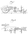
- Each of these conveyor belts 21, 22 merges with a respective conveyor path or belt which slopes towards the surface of the ground and of which one referenced 21′ is shown in Figures 1 and 2.
- the free end of the inclined conveyor path 21′ discharges into a feed chute 23, the height or which can preferably be adjusted and which extends in the axial direction of the machine, approximately at right angles to the conveyor path 21′.
- the feed chute 23 is inclined rearwardly and downwardly, and the free end of the chute discharges beneath the level of the ground 25 at a small distance above the bottom 27 of the planting furrows 28.
- a linearly displaceable device Arranged for reciprocating movement in the feed chute 23 is a linearly displaceable device which is carried by the chute 23 and which has the form, for instance, of a relatively long plunger 29 (Figure 2) which in one working phase is intended to permit the first plant in the row of plants on the inclined conveyor path 21′ to enter the feed chute 23, and in another working phase is intended to be moved linearly in a manner such as to move the plant (generally identified at 30 in Figures 1, 2) transferred to the feed chute to the planting furrow 28, at the same time as the plunger 29 forms a barrier which prevents the plant next in line on the conveyor path 21′ from moving into the feed chute 23.
- a relatively long plunger 29 Figure 2
- Figure 2 which in one working phase is intended to permit the first plant in the row of plants on the inclined conveyor path 21′ to enter the feed chute 23, and in another working phase is intended to be moved linearly in a manner such as to move the plant (generally identified at 30 in Figures 1, 2) transferred to the feed chute to the planting furrow 28,
- the end of the plunger 29 is bevelled and thereby functions to guide the plant 30 in a manner to ensure that the plant will take a correct position in the furrow 28.
- the result of this particular feature is that the plant to be deposited in the furrow will have only a short free-fall and the risk of the plant toppling when coming into contact with the soil is eliminated almost totally. Because the height of the chute 23 can be adjusted, the chute can be adapted to varying furrow depths.
- the inventive planting machine is provided with an arrangement whose construction is illustrated in Figures 1 and 2 and which comprises an arm 31 which extends in the longitudinal direction of the machine, parallel with the chute 23. Pivotally connected with one end 32 of the arm 31 is a first extension 33 and a second extension 34 which is spaced radially from said first extension 33 and positioned parallel therewith.
- These extensions 33, 34 which execute a synchronous working movement through the intermediary of a cross-shaft 35, are positioned so as to accomodate therebetween the plant 30 located in the furrow, and each of the extensions presents mutually facing, adjustable blades 35, 36.
- the arm 31 executes a working movement which results in the blades 35, 36 being moved down into the soil, whereupon the blades, as a result of their angled positions (figure 2) lift soil up around the lower parts of the plants so as to provide initial conditions for plant vegetation.
- the inventive planting machine may be self-propelling, wherewith the movements of the described machine components can be effected, e.g. through the intermediary of the output shaft of the engine.
- This would restrict the use of the machine solely to that of planting plants, which can hardly be defended economically in view of the investment costs of such a machine. Consequently, it is preferred to construct the inventive planting machine so that it can be pulled by a tractor or some other towing vehicle.
- the Figures, particularly Figures 1 and 2 of the drawings illustrate a preferred embodiment of the transmission system, only one half of the machine being shown.
- the rotating carrier wheels 11, 12 of the planting machine are interconnected, in a known manner, through the rotatable shaft 37, which has firmly arranged thereon a toothed ring 38.
- a rotatable frame shaft 39 is arranged on a rotatable frame shaft 39 .
- the toothed rings 38 and 40 are interconnected by an endless chain 41.
- the shafts 37 and 39 are provided with journal bushes in a known manner.
- the shaft 39 carries a second toothed ring 42, which is connected by means of an endless chain 43 with a third toothed ring 45 firm severelyly mounted on a rotational shaft 44.
- a further toothed ring 46 is arranged immediately beneath the third toothed ring 45 and is firmly mounted on a further shaft 47, the toothed rings 45, 46 being connected together by means of an endless chain 48.
- one end of the shaft 43 carries a pin 60 which is pivotally connected to the arm 31.
- the shaft 43 is also provided with a short arm 49 which is pivotally connected to an arm 50, which in turn is pivotally connected to the plunger 29 arranged for reciprocating movement in the chute 23.
- the horizontal conveyor belt or path 21 which, can be driven in the manner desired and on which the plants to be planted are placed by the machine operator, merges with the inclined conveyor belt or path 21′ and the plants are moved singly and sequentially downwards in a direction towards the outfeed chute 23.
- the carrier wheels 11 and 12 rotate and therewith also cause the wheel shaft 37 to rotate.
- This rotary movement is transferred to the rotatable intermediate shaft 39, via the toothed rings 38, 40 and the endless belt 41.
- Rotary movement of the shaft 39 is, in turn, transferred via the toothed rings 42, 45 to the rotatable third shaft 44, the rotary movement of which causes the arm 49 to pivot and therewith cause the plunger 29 to move reciprocatingly in the channel 23.
- the plunger 29 will normally present an obstacle to the transfer of a plant to the chute 23, although when the plunger 29 is withdrawn to a terminal position to an extent such that the discharge end of the conveyor belt 21′ is uncovered, the outermost plant on the conveyor belt is able to move into the feed chute 23.
- This movement phase in which the discharge end of the conveyor is uncovered is extremely short, however, and when the plunger moves towards the free end of the chute 23 in the following working phase, the plunger 29 will push along the plant discharged from the conveyor 21′ while, at the same time, ensuring that the now outermost plant on the conveyor belt 21′ if blocked against further forward movement.
- the plunger 29 When the plunger 29 has reached the other terminal position in the chute 23, the plant to be planted is located immediately above the bottom of the planting furrow 27 and the extent of free-fall of the plant is very slight. Subsequent to the plant 30 being deposited in the furrow, the plunger 29 is withdrawn so as to permit the next plant on the conveyor belt 21′ to be released while, at the same time, the arm 31 moves and causes the blades 36 located on either side of the deposited plant 30 to move downwards and obliquely (Figure 2) so as to lift soil up and around the lower part of the plant 30.
- the machine illustrated in Figure 1 has two stations and two operators and the transmission system illustrated in Figure 1 and 2 is naturally found on the other side or half of the machine, although not shown in these Figures. It will also be understood that the machine can have any desired width and that the stations, plungers 29 etc. may be more than two.
Abstract
Description
- The present invention relates to a planting machine which is intended for depositing plants in furrows formed in the ground, earth or soil, hereinafter generally refered to as soil, and which comprises a frame carried by a number of rotatable wheels and one or more plant holding stations localized at a distance from the level of the soil, and further comprising one or more conveyors for feeding plants conveyed thereby sequentially down onto the soil such as to plant the plants singly in said furrows, and means for ensuring that only one plant at a time is placed in a furrow.
- A planting machine of the aforesaid kind in known from EP 062 917. This machine includes a plant holding station, and the plants are transferred singly from this station to a driven conveyor belt or path which is inclined slightly in the forward direction of the machine. Co-acting with the conveyor belt is a gripping arrangement which grips the outermost plant on the conveyor belt at the same time as the next plant in line on the belt is prevented from further movement by a stop arrangement. The gripping arrangement comprises a mechanism which, through the intermediary of an excentric disc or plate, lifts-up the gripped plant and then lowers the plant against second transfer means, whereafter the plant is finally placed in the planting furrow. The gripping arrangement, which co-acts with a planting arm, is intended to move through a relatively long distance, which unavoidably limits the rate at which the plants are planted and therewith also the speed at which the machine works.
- The object of the present invention is to provide an improved planting machine of the kind described in the introduction, such that the machine will have a simpler construction and a much higher planting capacity.
- A significant feature of the invention resides in the fact that the conveyor path or paths discharge into a chute which extends substantially in the axial direction of the machine and in the proximity of the soil surface and in which a linearly displaceable device is intended to uncover the outlet of a conveyor belt in one machine-working phase, so as to permit a plant to be transferred to said chute, and to move said transferred plant towards the free end of the chute in another machine-working phase and placing the plant in the planting furrow while simultaneously closing the outlet of the conveyor belt or path.
- Because the linearly displaceable device will ensure that plants are only fed singly from the machine and will also ensure that the plants are planted in the planting furrows, such an arrangement will provide a simplified machine construction. The planting chute, in which the displaceable member moves backwards and forwards, can be given a short length, and by making the length of stroke of the displaceable member correspondingly short there is obtained a much higher planting rate than was previously possible with the known planting machine.
- Another object of the present invention is to combine an increased planting rate with a facility for ensuring that the plants are positioned correctly in the planting furrow. It will be understood that a fast planting rate is quite without meaning if the plants are placed crookedly in the furrow, thereby requiring the crooked plants to be straightened manually after the machine has passed.
- The improved planting machine will therefore include the feature Claim 2, according to which the free end of the chute discharges beneath the surface of the soil but above the bottom of the planting furrow, wherewith the plant being deposited in the furrow is guided until the very moment that its roots or bottom end comes into contact with the bottom of the planting furrow.
- A further feature of the improved planting machine is set forth in claim 3, according to which means are provided for lifting-up soil on opposite sides of the plant immediately the plant has been placed in the planting furrow, thereby initially earthing up the plant.
- Consequently, no separate machine is required for firming the plants in the soil, such firming of the soil being necessary to initiate vegetation of the plants.
- Advantageous embodiments of the improved planting machine are set forth in the remainder of the depending claims.
- An exemplifying embodiment of the invention will now be described with reference to the accompanying drawings, in which
- Figure 1 is a schematic side view of the improved planting machine;
- Figure 2 is a schematic view from above of part of the planting machine according to the invention; and
- Figure 3 is a schematic view from above of the planting machine according to the invention and of which Figure 2 illustrates a part.
- Figure 3 illustrates an inventive planting machine from above, this machine including a
frame 10 which is carried byrotatable wheels centre wheel 13 which is arranged at the rear end of the machine. The forward direction of the machine is indicated by the arrow A in Figure 3, and the machine is intended to be detachably connected to a towing vehicle by means of theframe part 14. Arranged in the upper part of the machine of the illustrated embodiment are two main holding or storingstations 15 and 16, which are intended to hold or store plants intended to be planted in the ground, earth or soil, hereinafter generally referred to as soil, the under parts of which stations are either cubic or round in shape. Thereference numerals stations 19 and 20 and place the plants in a row on a horizontal, or substantially horizontal conveyor belt orpath conveyor belts - The free end of the
inclined conveyor path 21′ discharges into afeed chute 23, the height or which can preferably be adjusted and which extends in the axial direction of the machine, approximately at right angles to theconveyor path 21′. Thefeed chute 23 is inclined rearwardly and downwardly, and the free end of the chute discharges beneath the level of theground 25 at a small distance above thebottom 27 of theplanting furrows 28. - Arranged for reciprocating movement in the
feed chute 23 is a linearly displaceable device which is carried by thechute 23 and which has the form, for instance, of a relatively long plunger 29 (Figure 2) which in one working phase is intended to permit the first plant in the row of plants on theinclined conveyor path 21′ to enter thefeed chute 23, and in another working phase is intended to be moved linearly in a manner such as to move the plant (generally identified at 30 in Figures 1, 2) transferred to the feed chute to theplanting furrow 28, at the same time as theplunger 29 forms a barrier which prevents the plant next in line on theconveyor path 21′ from moving into thefeed chute 23. As will be seen from Figure 1, the end of theplunger 29 is bevelled and thereby functions to guide theplant 30 in a manner to ensure that the plant will take a correct position in thefurrow 28. The result of this particular feature is that the plant to be deposited in the furrow will have only a short free-fall and the risk of the plant toppling when coming into contact with the soil is eliminated almost totally. Because the height of thechute 23 can be adjusted, the chute can be adapted to varying furrow depths. - In order for the plants to vegetate, it is necessary to surround the stems of the plants with soil or earth. To this end, the inventive planting machine is provided with an arrangement whose construction is illustrated in Figures 1 and 2 and which comprises an
arm 31 which extends in the longitudinal direction of the machine, parallel with thechute 23. Pivotally connected with oneend 32 of thearm 31 is afirst extension 33 and asecond extension 34 which is spaced radially from saidfirst extension 33 and positioned parallel therewith. Theseextensions cross-shaft 35, are positioned so as to accomodate therebetween theplant 30 located in the furrow, and each of the extensions presents mutually facing,adjustable blades plant 30 is deposited in a planting furrow with the aid of theplunger 29 and the plunger commences a return stroke, thearm 31 executes a working movement which results in theblades - As all who are skilled in this art will understand, the aforedescribed machine components can be driven in many different ways.
- For example, the inventive planting machine may be self-propelling, wherewith the movements of the described machine components can be effected, e.g. through the intermediary of the output shaft of the engine. This, however, would restrict the use of the machine solely to that of planting plants, which can hardly be defended economically in view of the investment costs of such a machine. Consequently, it is preferred to construct the inventive planting machine so that it can be pulled by a tractor or some other towing vehicle. In accordance herewith, the Figures, particularly Figures 1 and 2 of the drawings, illustrate a preferred embodiment of the transmission system, only one half of the machine being shown.
- The rotating
carrier wheels rotatable shaft 37, which has firmly arranged thereon atoothed ring 38. Arranged on arotatable frame shaft 39 is a secondtoothed ring 40. Thetoothed rings endless chain 41. Although not shown, theshafts shaft 39 carries a secondtoothed ring 42, which is connected by means of anendless chain 43 with a third toothed ring 45 firmly mounted on arotational shaft 44. A furthertoothed ring 46 is arranged immediately beneath the third toothed ring 45 and is firmly mounted on afurther shaft 47, thetoothed rings 45, 46 being connected together by means of anendless chain 48. As will be seen from Figure 2, one end of theshaft 43 carries apin 60 which is pivotally connected to thearm 31. Theshaft 43 is also provided with ashort arm 49 which is pivotally connected to anarm 50, which in turn is pivotally connected to theplunger 29 arranged for reciprocating movement in thechute 23. - The aforedescribed transmission system operates in the following manner:
- The horizontal conveyor belt or
path 21 which, can be driven in the manner desired and on which the plants to be planted are placed by the machine operator, merges with the inclined conveyor belt orpath 21′ and the plants are moved singly and sequentially downwards in a direction towards theoutfeed chute 23. As the planting machine according to the invention is pulled forwards thecarrier wheels wheel shaft 37 to rotate. This rotary movement is transferred to the rotatableintermediate shaft 39, via thetoothed rings endless belt 41. Rotary movement of theshaft 39 is, in turn, transferred via thetoothed rings 42, 45 to the rotatablethird shaft 44, the rotary movement of which causes thearm 49 to pivot and therewith cause theplunger 29 to move reciprocatingly in thechannel 23. As will be seen from Figure 2, theplunger 29 will normally present an obstacle to the transfer of a plant to thechute 23, although when theplunger 29 is withdrawn to a terminal position to an extent such that the discharge end of theconveyor belt 21′ is uncovered, the outermost plant on the conveyor belt is able to move into thefeed chute 23. This movement phase in which the discharge end of the conveyor is uncovered is extremely short, however, and when the plunger moves towards the free end of thechute 23 in the following working phase, theplunger 29 will push along the plant discharged from theconveyor 21′ while, at the same time, ensuring that the now outermost plant on theconveyor belt 21′ if blocked against further forward movement. When theplunger 29 has reached the other terminal position in thechute 23, the plant to be planted is located immediately above the bottom of theplanting furrow 27 and the extent of free-fall of the plant is very slight. Subsequent to theplant 30 being deposited in the furrow, theplunger 29 is withdrawn so as to permit the next plant on theconveyor belt 21′ to be released while, at the same time, thearm 31 moves and causes theblades 36 located on either side of the depositedplant 30 to move downwards and obliquely (Figure 2) so as to lift soil up and around the lower part of theplant 30. - Planting of the plants continues in this way, each plant being firmed in the planting furrow by the soil lifted around the lower parts thereof, and it will be understood that the faster the planting machine is moved, the more plants that are planted per unit of time. Since the working machine components are driven by a common drive source, i.e. the
shaft 37, the co-action between theplunger 29 and thearm 31 will remain the same and ensure correct depositing of the plants. - The machine illustrated in Figure 1 has two stations and two operators and the transmission system illustrated in Figure 1 and 2 is naturally found on the other side or half of the machine, although not shown in these Figures. It will also be understood that the machine can have any desired width and that the stations,
plungers 29 etc. may be more than two.
Claims (8)
Priority Applications (1)
| Application Number | Priority Date | Filing Date | Title |
|---|---|---|---|
| AT88850304T ATE89114T1 (en) | 1987-10-19 | 1988-09-15 | PLANTER. |
Applications Claiming Priority (2)
| Application Number | Priority Date | Filing Date | Title |
|---|---|---|---|
| SE8704059 | 1987-10-19 | ||
| SE8704059A SE8704059L (en) | 1987-10-19 | 1987-10-19 | PLANTSAETTNINGSMASKIN |
Publications (2)
| Publication Number | Publication Date |
|---|---|
| EP0313530A1 true EP0313530A1 (en) | 1989-04-26 |
| EP0313530B1 EP0313530B1 (en) | 1993-05-12 |
Family
ID=20369927
Family Applications (1)
| Application Number | Title | Priority Date | Filing Date |
|---|---|---|---|
| EP88850304A Expired - Lifetime EP0313530B1 (en) | 1987-10-19 | 1988-09-15 | A planting machine |
Country Status (8)
| Country | Link |
|---|---|
| EP (1) | EP0313530B1 (en) |
| AT (1) | ATE89114T1 (en) |
| DE (1) | DE3880957D1 (en) |
| DK (1) | DK510088A (en) |
| FI (1) | FI884760A (en) |
| NO (1) | NO884621L (en) |
| PT (1) | PT88801A (en) |
| SE (1) | SE8704059L (en) |
Cited By (1)
| Publication number | Priority date | Publication date | Assignee | Title |
|---|---|---|---|---|
| US4947582A (en) * | 1986-07-07 | 1990-08-14 | Visser 's-Gravendeel Holding B.V. | Apparatus and method for planting out plants |
Citations (3)
| Publication number | Priority date | Publication date | Assignee | Title |
|---|---|---|---|---|
| DE928130C (en) * | 1949-09-27 | 1955-05-23 | August Gustav Witte | Transplanter |
| GB1557004A (en) * | 1976-10-08 | 1979-12-05 | Philips P | Planting machine |
| EP0062917A1 (en) * | 1981-04-14 | 1982-10-20 | Reinhold Heilmann | Seedling transplanter |
-
1987
- 1987-10-19 SE SE8704059A patent/SE8704059L/en not_active Application Discontinuation
-
1988
- 1988-09-13 DK DK510088A patent/DK510088A/en not_active Application Discontinuation
- 1988-09-15 AT AT88850304T patent/ATE89114T1/en not_active IP Right Cessation
- 1988-09-15 DE DE8888850304T patent/DE3880957D1/en not_active Expired - Lifetime
- 1988-09-15 EP EP88850304A patent/EP0313530B1/en not_active Expired - Lifetime
- 1988-10-14 FI FI884760A patent/FI884760A/en not_active Application Discontinuation
- 1988-10-18 NO NO88884621A patent/NO884621L/en unknown
- 1988-10-19 PT PT88801A patent/PT88801A/en not_active Application Discontinuation
Patent Citations (3)
| Publication number | Priority date | Publication date | Assignee | Title |
|---|---|---|---|---|
| DE928130C (en) * | 1949-09-27 | 1955-05-23 | August Gustav Witte | Transplanter |
| GB1557004A (en) * | 1976-10-08 | 1979-12-05 | Philips P | Planting machine |
| EP0062917A1 (en) * | 1981-04-14 | 1982-10-20 | Reinhold Heilmann | Seedling transplanter |
Cited By (1)
| Publication number | Priority date | Publication date | Assignee | Title |
|---|---|---|---|---|
| US4947582A (en) * | 1986-07-07 | 1990-08-14 | Visser 's-Gravendeel Holding B.V. | Apparatus and method for planting out plants |
Also Published As
| Publication number | Publication date |
|---|---|
| DK510088A (en) | 1989-04-20 |
| ATE89114T1 (en) | 1993-05-15 |
| FI884760A0 (en) | 1988-10-14 |
| NO884621D0 (en) | 1988-10-18 |
| SE8704059D0 (en) | 1987-10-19 |
| SE8704059L (en) | 1989-05-07 |
| PT88801A (en) | 1989-07-31 |
| FI884760A (en) | 1989-04-20 |
| EP0313530B1 (en) | 1993-05-12 |
| DE3880957D1 (en) | 1993-06-17 |
| DK510088D0 (en) | 1988-09-13 |
| NO884621L (en) | 1989-04-20 |
Similar Documents
| Publication | Publication Date | Title |
|---|---|---|
| US4156395A (en) | High-speed planting method and machine | |
| US6997120B2 (en) | Planting apparatus and method | |
| KR101938081B1 (en) | Sweet potato seedling transplanter | |
| US3963138A (en) | Cane planter | |
| CN106612791A (en) | Rice seeding thrower | |
| CN113383628A (en) | High-speed pot seedling field planting machine | |
| EP0571497A1 (en) | Method and apparatus for harvesting and bundling plants. | |
| EP0258293B1 (en) | Seedling planting machine | |
| US4266490A (en) | Sugar cane planter | |
| EP1624743B1 (en) | A method and apparatus for transporting seedlings in a planting machine | |
| US5641008A (en) | Potting machine | |
| EP0313530B1 (en) | A planting machine | |
| CN110178503B (en) | Hand-held corn seedling transplanter | |
| US3107637A (en) | Pineapple planter | |
| US4273168A (en) | Apparatus and method for harvesting trees | |
| EP0744120B1 (en) | Method and apparatus for harvesting and bunching agricultural produce and/of market garden produce | |
| CN208242203U (en) | A kind of two row of sugarcane plantation automatic sorting device | |
| EP1472924A1 (en) | A method and apparatus for transporting seedling trays in a planting machine | |
| EP0596851A1 (en) | Machine for planting slip plants | |
| EP1472923A1 (en) | A method and apparatus for regular delivery of seedling in a planting vehicle to the soil | |
| EP0515411B1 (en) | Potato planter | |
| US4696241A (en) | Cane billet planter | |
| US3426516A (en) | Asparagus harvester | |
| US3578088A (en) | Plant harvesting machine | |
| GB2287167A (en) | A hollow tine spiking machine |
Legal Events
| Date | Code | Title | Description |
|---|---|---|---|
| PUAI | Public reference made under article 153(3) epc to a published international application that has entered the european phase |
Free format text: ORIGINAL CODE: 0009012 |
|
| AK | Designated contracting states |
Kind code of ref document: A1 Designated state(s): AT BE CH DE ES FR GB GR IT LI NL |
|
| 17P | Request for examination filed |
Effective date: 19890907 |
|
| 17Q | First examination report despatched |
Effective date: 19910718 |
|
| GRAA | (expected) grant |
Free format text: ORIGINAL CODE: 0009210 |
|
| AK | Designated contracting states |
Kind code of ref document: B1 Designated state(s): AT BE CH DE ES FR GB GR IT LI NL |
|
| PG25 | Lapsed in a contracting state [announced via postgrant information from national office to epo] |
Ref country code: IT Free format text: LAPSE BECAUSE OF FAILURE TO SUBMIT A TRANSLATION OF THE DESCRIPTION OR TO PAY THE FEE WITHIN THE PRESCRIBED TIME-LIMIT;WARNING: LAPSES OF ITALIAN PATENTS WITH EFFECTIVE DATE BEFORE 2007 MAY HAVE OCCURRED AT ANY TIME BEFORE 2007. THE CORRECT EFFECTIVE DATE MAY BE DIFFERENT FROM THE ONE RECORDED. Effective date: 19930512 Ref country code: ES Free format text: THE PATENT HAS BEEN ANNULLED BY A DECISION OF A NATIONAL AUTHORITY Effective date: 19930512 Ref country code: DE Effective date: 19930512 Ref country code: LI Effective date: 19930512 Ref country code: AT Effective date: 19930512 Ref country code: CH Effective date: 19930512 Ref country code: FR Effective date: 19930512 Ref country code: GR Free format text: LAPSE BECAUSE OF FAILURE TO SUBMIT A TRANSLATION OF THE DESCRIPTION OR TO PAY THE FEE WITHIN THE PRESCRIBED TIME-LIMIT Effective date: 19930512 Ref country code: NL Effective date: 19930512 Ref country code: BE Effective date: 19930512 |
|
| REF | Corresponds to: |
Ref document number: 89114 Country of ref document: AT Date of ref document: 19930515 Kind code of ref document: T |
|
| REF | Corresponds to: |
Ref document number: 3880957 Country of ref document: DE Date of ref document: 19930617 |
|
| REG | Reference to a national code |
Ref country code: CH Ref legal event code: PL |
|
| PG25 | Lapsed in a contracting state [announced via postgrant information from national office to epo] |
Ref country code: GB Effective date: 19930915 |
|
| EN | Fr: translation not filed | ||
| NLV1 | Nl: lapsed or annulled due to failure to fulfill the requirements of art. 29p and 29m of the patents act | ||
| GBPC | Gb: european patent ceased through non-payment of renewal fee |
Effective date: 19930915 |
|
| PLBE | No opposition filed within time limit |
Free format text: ORIGINAL CODE: 0009261 |
|
| STAA | Information on the status of an ep patent application or granted ep patent |
Free format text: STATUS: NO OPPOSITION FILED WITHIN TIME LIMIT |