EP0312821B1 - Blood pressure cuff harness - Google Patents
Blood pressure cuff harness Download PDFInfo
- Publication number
- EP0312821B1 EP0312821B1 EP88116203A EP88116203A EP0312821B1 EP 0312821 B1 EP0312821 B1 EP 0312821B1 EP 88116203 A EP88116203 A EP 88116203A EP 88116203 A EP88116203 A EP 88116203A EP 0312821 B1 EP0312821 B1 EP 0312821B1
- Authority
- EP
- European Patent Office
- Prior art keywords
- cuff
- blood pressure
- arm
- harness
- support member
- Prior art date
- Legal status (The legal status is an assumption and is not a legal conclusion. Google has not performed a legal analysis and makes no representation as to the accuracy of the status listed.)
- Expired
Links
Images
Classifications
-
- A—HUMAN NECESSITIES
- A61—MEDICAL OR VETERINARY SCIENCE; HYGIENE
- A61B—DIAGNOSIS; SURGERY; IDENTIFICATION
- A61B5/00—Measuring for diagnostic purposes; Identification of persons
- A61B5/02—Detecting, measuring or recording for evaluating the cardiovascular system, e.g. pulse, heart rate, blood pressure or blood flow
- A61B5/021—Measuring pressure in heart or blood vessels
- A61B5/022—Measuring pressure in heart or blood vessels by applying pressure to close blood vessels, e.g. against the skin; Ophthalmodynamometers
- A61B5/02233—Occluders specially adapted therefor
Definitions
- This invention relates to a medical support harness, and more particularly, to a harness for holding a blood pressure cuff in the proper position on the arm for excented periods.
- the blood pressure of a person is presently used as an important factor in determining the overall health of an individual. Further, it is often important either to record the blood pressure of an individual at a given time during the day or to record the variations in blood pressure throughout the day.
- blood pressure testing devices are available that are worn for extended periods, such as 24 to 48 hours. The blood pressure is taken and recorded on a regular basis throughout this extended period.
- the patient wears a blood pressure cuff the entire monitoring period.
- An electronic system tests and records the blood pressure of the person every 20 or so minutes throughout the monitoring period.
- a small air pressure pump, electronic control, sensors and recorder are provided which pump up the cuff and record the blood pressure at the selected timed intervals.
- the cuff often has sensors to perform the function of determining the blood pressure. It is therefore important that the cuff not rotate excessively so that the sensors and bladder are in the correct position to obtain an accurate reading of the blood pressure.
- the individual wearing the blood pressure cuff is required to wear the cuff for the entire test period and keep it in the correct position so that the blood pressure readings are accurate.
- the blood pressure cuff tends to slip down or move from its correct position on the arm. This is because during those intervals when a blood pressure reading is not being taken, the blood pressure cuff is deflated and fits more loosely around the arm.
- the cuff If the cuff is worn for an extended period of time, it is not inflated most of the time.
- the only force acting to prevent the cuff from moving is the friction from contact with the arm and the full weight of the cuff is borne by the arm. Further, the tightness of the fit depends upon the circumference of the patient's arm. As the person flexes and stretches his arm, the circumference and shape of the arm will change and thus the fit of the cuff around the arm will vary throughout the day.
- the problem of movement of the blood pressure cuff is particularly acute in overweight people. It is not uncommon for a person, particularly if he is overweight, to have a somewhat larger circumference at the top of his arm towards the shoulder than the circumference towards the elbow, gradually decreasing from the shoulder down. Thus, the arm of the person is in the shape of an inverted cone. To deal with this, the blood pressure cuff for such an individual may be made in the shape of an inverted cone so as to more closely fit the contour of the arm. However, this does not solve the problem of downward slipping or rotating of the cuff. The result is that an inverted cone (the arm) has another inverted cone (the cuff) wrapped around it, which will easily slip downward.
- the tape may contain a skin irritant which causes great discomfort to the skin while being worn. Further, when the tape is removed, there is discomfort from the pulling of hairs on the person's arms. Further, the tape often becomes loose if the person is moving his arm frequently or if the person has an oily skin or begins to perspire.
- a harness to a blood pressure cuff and extending the harness to the shoulder of the user so that some or all of the weight of the cuff is carried by the shoulder.
- a strap is attached to the harness in the shoulder region of the user and goes under the other arm of the user to hold that part of the harness in the correct position on the shoulder of the user.
- Clasps are connected to the end of the harness support member which can be removably attached to the blood pressure cuff.
- the cuff support member extends from this shoulder down the arm and attaches to the blood pressure cuff.
- the user places his head and arm through the strap so that one of the straps extends across the front of the user and the other strap extends across the back of the user to the shoulder region for holding the support member in the correct position at the shoulder region.
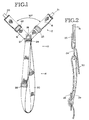
- the harness 10 as illustrated in Figures 1 and 2, includes a cuff support member 12 and a shoulder support member 14.
- the cuff support member 12 has two support arms 16 and 18, respectively, extending at 90° angles with respect to each other.
- the support arms 16, 18 of the cuff support member 12 are sewn at junction 26 such that the two support arms 16, 18 extend away from the fastener at a 90° angle with respect to each other.
- a retaining tab 27 is sewn with the support arms 16, 18, and it is looped through the fastener to connect the cuff support member 12 to the shoulder support member 14.
- the support arms 16, 18 are looped and connected into respective adjustment sliders 22, 23 to allow the length of the support arms 16, 18 to be adjusted.
- Clasps 20 and 21 are connected in the respective loops of each of the support arms 16, 18. When the clasps 20, 21 are opened, a portion of the blood pressure cuff may be inserted therein and the clasps closed to provide a firm attachment to the blood pressure cuff by the clasp. The clasp may be easily opened for removal of the blood pressure cuff. Clasps of this type are well known and are often used in suspenders. Other removable attachment devices, such as VelcroTM, buttons, etc., could be used if desired.
- the shoulder support member 14 includes an elastic strap 30 having one end looped around a fastener 24.
- a slider 28 in the looped end of the strap 30 permits easy adjustment of the length of the strap 30.
- the other end of the strap 30 is sewn into the same junction 26 with the support arms 16, 18.
- the strap 30 is formed with a one-half twist to provide complete contact and comfort as it extends from the shoulder to under the other arm.
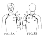
- FIGs 3A and 3B illustrate a person wearing the harness attached to a blood pressure cuff.
- the blood pressure cuff 32 is wrapped around the arm of the person in a manner well known in the art.
- Clasp 21 is attached to the front of the blood pressure cuff.
- Support arm 18 is connected to clasp 21 and extends up the front of the arm to the shoulder region of the user.
- support arm 16 is attached by clasp 20 to the rear portion of the blood pressure cuff, as shown in Figure 3B.
- Support arm 16 extends from the blood pressure cuff up the back of the arm to the shoulder region of the user.
- the two support arms are joined together at junction 26 above the blood pressure cuff on the shoulder region of the user.
- the weight of the blood pressure cuff is supported through the straps by the shoulder of the person.
- the blood pressure cuff does not slip down the arm towards the elbow of the user even when worn for extended periods. Further, the support arms prevent rotation of the cuff.
- the blood pressure cuff is held in the correct position for each of the readings.
- the blood pressure cuff may now be wrapped less tightly around the person's arm. The inward pressure of the cuff on the arm need not support the cuff to keep it from slipping downward or rotating. Flexing or extending the arm will not affect the position of the cuff.
- Strap 30 is provided for holding the support arms in the correct position on the shoulder of the user. This strap 30 is connected to the junction 26 and through a fastener to the cuff support member 12. Strap 30 extends from the shoulder region above the blood pressure cuff across the back of the person and under the arm of the individual, as in Figures 3A and 3B. In this way, the cuff support member 12 is held in the proper and comfortable position in the shoulder region of the user for extended periods of time.
- the strap 30 may be worn by the user with a portion of the strap extending across the chest and a portion across the back, with the loop extending under the arm. In certain circumstances, this may provide more comfort and better positioning than extending both straps across the back.
- the harness is made of an elastic material, with straps 30, 16 and 18 being elastic. This provides comfort for the user. The user may continue his normal activities through the extended monitoring period and have full ability to move his limbs and body without displacing the blood pressure cuff.
- the cuff support member 12 has two support arms 16, 18; however, the cuff support member 12 could be comprised of a single support arm properly positioned to keep the blood pressure cuff in the correct position throughout the monitoring period. Further, a single extending support member with an inverted V connection or other type of positioning support may also be used.
Landscapes
- Health & Medical Sciences (AREA)
- Life Sciences & Earth Sciences (AREA)
- Cardiology (AREA)
- Vascular Medicine (AREA)
- Engineering & Computer Science (AREA)
- Medical Informatics (AREA)
- Physics & Mathematics (AREA)
- Ophthalmology & Optometry (AREA)
- Biophysics (AREA)
- Pathology (AREA)
- Dentistry (AREA)
- Biomedical Technology (AREA)
- Heart & Thoracic Surgery (AREA)
- Physiology (AREA)
- Molecular Biology (AREA)
- Surgery (AREA)
- Animal Behavior & Ethology (AREA)
- General Health & Medical Sciences (AREA)
- Public Health (AREA)
- Veterinary Medicine (AREA)
- Measuring Pulse, Heart Rate, Blood Pressure Or Blood Flow (AREA)
Description
- This invention relates to a medical support harness, and more particularly, to a harness for holding a blood pressure cuff in the proper position on the arm for excented periods.
- The blood pressure of a person is presently used as an important factor in determining the overall health of an individual. Further, it is often important either to record the blood pressure of an individual at a given time during the day or to record the variations in blood pressure throughout the day. Presently, blood pressure testing devices are available that are worn for extended periods, such as 24 to 48 hours. The blood pressure is taken and recorded on a regular basis throughout this extended period. In a typical blood pressure monitoring program, the patient wears a blood pressure cuff the entire monitoring period. An electronic system tests and records the blood pressure of the person every 20 or so minutes throughout the monitoring period. A small air pressure pump, electronic control, sensors and recorder are provided which pump up the cuff and record the blood pressure at the selected timed intervals.
- The cuff often has sensors to perform the function of determining the blood pressure. It is therefore important that the cuff not rotate excessively so that the sensors and bladder are in the correct position to obtain an accurate reading of the blood pressure.
- The individual wearing the blood pressure cuff is required to wear the cuff for the entire test period and keep it in the correct position so that the blood pressure readings are accurate. Unfortunately, during this extended period of 24 to 48 hours, the blood pressure cuff tends to slip down or move from its correct position on the arm. This is because during those intervals when a blood pressure reading is not being taken, the blood pressure cuff is deflated and fits more loosely around the arm.
- If the cuff is worn for an extended period of time, it is not inflated most of the time. The only force acting to prevent the cuff from moving is the friction from contact with the arm and the full weight of the cuff is borne by the arm. Further, the tightness of the fit depends upon the circumference of the patient's arm. As the person flexes and stretches his arm, the circumference and shape of the arm will change and thus the fit of the cuff around the arm will vary throughout the day.
- One solution is to wrap the cuff tightly around the arm when the cuff is not inflated. This is not satisfactory as it creates discomfort and the tightness of the fit will change as the person moves his arm. Further, the weight of the cuff is still borne solely by the arm in the general region of where the measurement is taken.
- The problem of movement of the blood pressure cuff is particularly acute in overweight people. It is not uncommon for a person, particularly if he is overweight, to have a somewhat larger circumference at the top of his arm towards the shoulder than the circumference towards the elbow, gradually decreasing from the shoulder down. Thus, the arm of the person is in the shape of an inverted cone. To deal with this, the blood pressure cuff for such an individual may be made in the shape of an inverted cone so as to more closely fit the contour of the arm. However, this does not solve the problem of downward slipping or rotating of the cuff. The result is that an inverted cone (the arm) has another inverted cone (the cuff) wrapped around it, which will easily slip downward.
- Another solution is to tape the cuff in position on the arm. While this does provide some additional support, it is not satisfactory solution. The tape may contain a skin irritant which causes great discomfort to the skin while being worn. Further, when the tape is removed, there is discomfort from the pulling of hairs on the person's arms. Further, the tape often becomes loose if the person is moving his arm frequently or if the person has an oily skin or begins to perspire.
- It is therefore an object of the invention to provide a harness for holding a blood pressure cuff in the correct position for extended periods of time.
- It is a further object of the invention to transfer the weight of the blood pressure cuff to a region different from the location where the measurements are being taken.
- It is a further object of the invention to provide a support for the blood pressure cuff having an elastic member extending to the shoulder, with the weight of the cuff being carried in part by the shoulder of the person and a strap extending from that shoulder to under the other arm of the user.
- These and other objects of the invention are provided by attaching a harness to a blood pressure cuff and extending the harness to the shoulder of the user so that some or all of the weight of the cuff is carried by the shoulder. A strap is attached to the harness in the shoulder region of the user and goes under the other arm of the user to hold that part of the harness in the correct position on the shoulder of the user. Clasps are connected to the end of the harness support member which can be removably attached to the blood pressure cuff. When wearing the harness, the user places one arm through the strap and extends the strap across his back to the shoulder of the other arm for holding the cuff support member in the correct position on the shoulder. The cuff support member extends from this shoulder down the arm and attaches to the blood pressure cuff. In the alternative, the user places his head and arm through the strap so that one of the straps extends across the front of the user and the other strap extends across the back of the user to the shoulder region for holding the support member in the correct position at the shoulder region.
-
- Figure 1 is a front elevational view of the harness in a flat position when not in use.
- Figure 2 is a side elevational view of a portion of the harness.
- Figures 3A and 3B are a front and back elevational view, respectively, of a person wearing the harness.
- The
harness 10, as illustrated in Figures 1 and 2, includes acuff support member 12 and ashoulder support member 14. Thecuff support member 12 has twosupport arms support arms cuff support member 12 are sewn atjunction 26 such that the two supportarms retaining tab 27 is sewn with thesupport arms cuff support member 12 to theshoulder support member 14. - The
support arms respective adjustment sliders support arms Clasps support arms clasps - The
shoulder support member 14 includes anelastic strap 30 having one end looped around afastener 24. Aslider 28 in the looped end of thestrap 30 permits easy adjustment of the length of thestrap 30. The other end of thestrap 30 is sewn into thesame junction 26 with thesupport arms strap 30 is formed with a one-half twist to provide complete contact and comfort as it extends from the shoulder to under the other arm. - Figures 3A and 3B illustrate a person wearing the harness attached to a blood pressure cuff. The
blood pressure cuff 32 is wrapped around the arm of the person in a manner well known in the art.Clasp 21 is attached to the front of the blood pressure cuff.Support arm 18 is connected toclasp 21 and extends up the front of the arm to the shoulder region of the user. Similarly,support arm 16 is attached byclasp 20 to the rear portion of the blood pressure cuff, as shown in Figure 3B.Support arm 16 extends from the blood pressure cuff up the back of the arm to the shoulder region of the user. The two support arms are joined together atjunction 26 above the blood pressure cuff on the shoulder region of the user. In this way, the weight of the blood pressure cuff is supported through the straps by the shoulder of the person. The blood pressure cuff does not slip down the arm towards the elbow of the user even when worn for extended periods. Further, the support arms prevent rotation of the cuff. When periodic readings are taken throughout the extended period, the blood pressure cuff is held in the correct position for each of the readings. The blood pressure cuff may now be wrapped less tightly around the person's arm. The inward pressure of the cuff on the arm need not support the cuff to keep it from slipping downward or rotating. Flexing or extending the arm will not affect the position of the cuff. -
Strap 30 is provided for holding the support arms in the correct position on the shoulder of the user. Thisstrap 30 is connected to thejunction 26 and through a fastener to thecuff support member 12.Strap 30 extends from the shoulder region above the blood pressure cuff across the back of the person and under the arm of the individual, as in Figures 3A and 3B. In this way, thecuff support member 12 is held in the proper and comfortable position in the shoulder region of the user for extended periods of time. - In the alternative, the
strap 30 may be worn by the user with a portion of the strap extending across the chest and a portion across the back, with the loop extending under the arm. In certain circumstances, this may provide more comfort and better positioning than extending both straps across the back. - The harness is made of an elastic material, with
straps - In the preferred embodiment, the
cuff support member 12 has twosupport arms cuff support member 12 could be comprised of a single support arm properly positioned to keep the blood pressure cuff in the correct position throughout the monitoring period. Further, a single extending support member with an inverted V connection or other type of positioning support may also be used.
Claims (6)
Applications Claiming Priority (2)
| Application Number | Priority Date | Filing Date | Title |
|---|---|---|---|
| US07/104,322 US4844306A (en) | 1987-10-02 | 1987-10-02 | Blood pressure cuff harness |
| US104322 | 1987-10-02 |
Publications (2)
| Publication Number | Publication Date |
|---|---|
| EP0312821A1 EP0312821A1 (en) | 1989-04-26 |
| EP0312821B1 true EP0312821B1 (en) | 1991-06-05 |
Family
ID=22299873
Family Applications (1)
| Application Number | Title | Priority Date | Filing Date |
|---|---|---|---|
| EP88116203A Expired EP0312821B1 (en) | 1987-10-02 | 1988-09-30 | Blood pressure cuff harness |
Country Status (4)
| Country | Link |
|---|---|
| US (1) | US4844306A (en) |
| EP (1) | EP0312821B1 (en) |
| JP (1) | JPH021222A (en) |
| DE (1) | DE3863159D1 (en) |
Families Citing this family (15)
| Publication number | Priority date | Publication date | Assignee | Title |
|---|---|---|---|---|
| US5054494A (en) * | 1989-12-26 | 1991-10-08 | U.S. Medical Corporation | Oscillometric blood pressure device |
| US5163450A (en) * | 1991-11-12 | 1992-11-17 | Gregory Cadichon | Harness for preventing gleno-humeral joint subluxation |
| US5203763A (en) * | 1992-02-04 | 1993-04-20 | Lajiness O Neill Renee | Dynamic sling |
| DE4221502C1 (en) * | 1992-07-01 | 1993-07-15 | Bauerfeind Gmbh & Co, 4152 Kempen, De | |
| DE29711255U1 (en) * | 1997-06-27 | 1997-09-18 | MIPM Mammendorfer Institut für Physik und Medizin GmbH, 82285 Hattenhofen | Device for temporarily pressing a blood vessel |
| CA2259889C (en) * | 1998-04-01 | 2005-02-01 | Andrew Godwin | Sports brace |
| US6471657B2 (en) | 2001-01-31 | 2002-10-29 | Spacelabs Medical, Inc. | User releasable and adjustable blood pressure cuff and method |
| US6767290B1 (en) * | 2003-02-28 | 2004-07-27 | Christopher K. Tan | Golf training aid |
| CN103006191A (en) * | 2011-09-23 | 2013-04-03 | 泰博科技股份有限公司 | Blood pressure measurement system and accessories set of the machine body |
| US8591488B2 (en) | 2012-01-31 | 2013-11-26 | Butterfly Health, Inc. | Devices and methods for treating accidental bowel leakage |
| EP3273920A4 (en) * | 2015-03-24 | 2019-01-02 | Avalanche Studio Pte Ltd | An arm immobilization apparatus and methods for wearing the apparatus |
| US9996981B1 (en) | 2016-03-07 | 2018-06-12 | Bao Tran | Augmented reality system |
| US9460557B1 (en) | 2016-03-07 | 2016-10-04 | Bao Tran | Systems and methods for footwear fitting |
| US10052026B1 (en) | 2017-03-06 | 2018-08-21 | Bao Tran | Smart mirror |
| EP3753443B1 (en) * | 2018-02-14 | 2024-04-03 | Makoto Suyama | Method and tool for preventing sliding down of shoulder belt, shoulder belt, and bag |
Family Cites Families (6)
| Publication number | Priority date | Publication date | Assignee | Title |
|---|---|---|---|---|
| US396061A (en) * | 1888-10-29 | 1889-01-15 | Artificial arm and hand | |
| FR442017A (en) * | 1912-04-01 | 1912-08-22 | Jules Spetter | Suspension strap placed on one shoulder for handling or transporting bags, suitcases, packages, etc. |
| US2408880A (en) * | 1943-04-28 | 1946-10-08 | Paul A Rebers | Artificial hand |
| US3120846A (en) * | 1962-09-12 | 1964-02-11 | Daniel A Fletcher | Pneumatic tourniquet |
| GB1422146A (en) * | 1972-05-26 | 1976-01-21 | Bowers Jolley G A | Device to assist the manual carrying of loads |
| US4598703A (en) * | 1985-10-02 | 1986-07-08 | Rolyan Manufacturing Co. Inc. | Hemi-arm sling |
-
1987
- 1987-10-02 US US07/104,322 patent/US4844306A/en not_active Expired - Fee Related
-
1988
- 1988-09-30 DE DE8888116203T patent/DE3863159D1/en not_active Expired - Lifetime
- 1988-09-30 EP EP88116203A patent/EP0312821B1/en not_active Expired
- 1988-10-01 JP JP63245899A patent/JPH021222A/en active Pending
Also Published As
| Publication number | Publication date |
|---|---|
| EP0312821A1 (en) | 1989-04-26 |
| US4844306A (en) | 1989-07-04 |
| DE3863159D1 (en) | 1991-07-11 |
| JPH021222A (en) | 1990-01-05 |
Similar Documents
| Publication | Publication Date | Title |
|---|---|---|
| US4844306A (en) | Blood pressure cuff harness | |
| US20250344996A1 (en) | Tissue interface | |
| US5617867A (en) | Tonometer mounting device | |
| EP1455640B1 (en) | Garment comprising medical sensors | |
| US4698848A (en) | Blouse for cardiac patients | |
| US6408200B1 (en) | EKG recording electrode device | |
| US4838276A (en) | Blood pressure cuff | |
| WO2006111875A1 (en) | Belt device | |
| US5271409A (en) | Non-bunching cinch ring engagement for blood pressure cuff | |
| JP2013034511A (en) | Sensor device attachment belt | |
| US4832040A (en) | Non-bunching cinch ring for self-applied blood pressure cuff | |
| US5772091A (en) | Support apparatus for a musical instrument | |
| US20230117365A1 (en) | Back Pillow and Back-Mounted Support Member for Measuring Body Parameters during Sleep and Facilitating Side Sleeping Orientation | |
| US5549116A (en) | Vest for the physiological monitoring of children | |
| US20040186539A1 (en) | Sling holder | |
| JPS63158039A (en) | Blood pressure measuring apparatus | |
| JP2818865B2 (en) | Clothing with respiratory sensor | |
| US3730164A (en) | Orthopedic sling | |
| US10893757B2 (en) | Kangaroo care wearable device and method thereof | |
| CN222189899U (en) | Information label structure and wrist strap using same | |
| CN216932011U (en) | Integrated trousers for andrological examination | |
| CN219700149U (en) | Prompt identification wristband with measuring ruler | |
| TWI228408B (en) | Method and device for monitoring blood pressure | |
| CN222323537U (en) | A fixed shoulder strap structure for an inflatable dynamic blood pressure monitor | |
| CN211381319U (en) | Dynamic blood pressure monitoring clothes |
Legal Events
| Date | Code | Title | Description |
|---|---|---|---|
| PUAI | Public reference made under article 153(3) epc to a published international application that has entered the european phase |
Free format text: ORIGINAL CODE: 0009012 |
|
| AK | Designated contracting states |
Kind code of ref document: A1 Designated state(s): CH DE FR GB IT LI |
|
| 17P | Request for examination filed |
Effective date: 19890724 |
|
| 17Q | First examination report despatched |
Effective date: 19900312 |
|
| GRAA | (expected) grant |
Free format text: ORIGINAL CODE: 0009210 |
|
| AK | Designated contracting states |
Kind code of ref document: B1 Designated state(s): CH DE FR GB IT LI |
|
| ITF | It: translation for a ep patent filed | ||
| REF | Corresponds to: |
Ref document number: 3863159 Country of ref document: DE Date of ref document: 19910711 |
|
| ET | Fr: translation filed | ||
| PLBE | No opposition filed within time limit |
Free format text: ORIGINAL CODE: 0009261 |
|
| STAA | Information on the status of an ep patent application or granted ep patent |
Free format text: STATUS: NO OPPOSITION FILED WITHIN TIME LIMIT |
|
| 26N | No opposition filed | ||
| PGFP | Annual fee paid to national office [announced via postgrant information from national office to epo] |
Ref country code: GB Payment date: 19920811 Year of fee payment: 5 |
|
| PGFP | Annual fee paid to national office [announced via postgrant information from national office to epo] |
Ref country code: FR Payment date: 19920827 Year of fee payment: 5 |
|
| PGFP | Annual fee paid to national office [announced via postgrant information from national office to epo] |
Ref country code: CH Payment date: 19920917 Year of fee payment: 5 |
|
| PGFP | Annual fee paid to national office [announced via postgrant information from national office to epo] |
Ref country code: DE Payment date: 19921030 Year of fee payment: 5 |
|
| PG25 | Lapsed in a contracting state [announced via postgrant information from national office to epo] |
Ref country code: LI Effective date: 19930930 Ref country code: GB Effective date: 19930930 Ref country code: CH Effective date: 19930930 |
|
| GBPC | Gb: european patent ceased through non-payment of renewal fee |
Effective date: 19930930 |
|
| PG25 | Lapsed in a contracting state [announced via postgrant information from national office to epo] |
Ref country code: FR Free format text: LAPSE BECAUSE OF NON-PAYMENT OF DUE FEES Effective date: 19940531 |
|
| REG | Reference to a national code |
Ref country code: CH Ref legal event code: PL |
|
| PG25 | Lapsed in a contracting state [announced via postgrant information from national office to epo] |
Ref country code: DE Effective date: 19940601 |
|
| REG | Reference to a national code |
Ref country code: FR Ref legal event code: ST |
|
| PG25 | Lapsed in a contracting state [announced via postgrant information from national office to epo] |
Ref country code: IT Free format text: LAPSE BECAUSE OF NON-PAYMENT OF DUE FEES Effective date: 20050930 |