EP0312382B1 - Control cable adjuster device - Google Patents
Control cable adjuster device Download PDFInfo
- Publication number
- EP0312382B1 EP0312382B1 EP88309641A EP88309641A EP0312382B1 EP 0312382 B1 EP0312382 B1 EP 0312382B1 EP 88309641 A EP88309641 A EP 88309641A EP 88309641 A EP88309641 A EP 88309641A EP 0312382 B1 EP0312382 B1 EP 0312382B1
- Authority
- EP
- European Patent Office
- Prior art keywords
- tubular housing
- rod
- end portion
- control cable
- termination
- Prior art date
- Legal status (The legal status is an assumption and is not a legal conclusion. Google has not performed a legal analysis and makes no representation as to the accuracy of the status listed.)
- Expired - Lifetime
Links
- 230000000295 complement effect Effects 0.000 claims description 5
- 230000000452 restraining effect Effects 0.000 claims description 4
- 230000002939 deleterious effect Effects 0.000 description 2
- 206010013710 Drug interaction Diseases 0.000 description 1
- 230000000694 effects Effects 0.000 description 1
- 239000013013 elastic material Substances 0.000 description 1
- 239000004519 grease Substances 0.000 description 1
- 230000003993 interaction Effects 0.000 description 1
Images

Classifications
-
- F—MECHANICAL ENGINEERING; LIGHTING; HEATING; WEAPONS; BLASTING
- F16—ENGINEERING ELEMENTS AND UNITS; GENERAL MEASURES FOR PRODUCING AND MAINTAINING EFFECTIVE FUNCTIONING OF MACHINES OR INSTALLATIONS; THERMAL INSULATION IN GENERAL
- F16D—COUPLINGS FOR TRANSMITTING ROTATION; CLUTCHES; BRAKES
- F16D65/00—Parts or details
- F16D65/38—Slack adjusters
- F16D65/40—Slack adjusters mechanical
- F16D65/52—Slack adjusters mechanical self-acting in one direction for adjusting excessive play
- F16D65/54—Slack adjusters mechanical self-acting in one direction for adjusting excessive play by means of direct linear adjustment
-
- F—MECHANICAL ENGINEERING; LIGHTING; HEATING; WEAPONS; BLASTING
- F16—ENGINEERING ELEMENTS AND UNITS; GENERAL MEASURES FOR PRODUCING AND MAINTAINING EFFECTIVE FUNCTIONING OF MACHINES OR INSTALLATIONS; THERMAL INSULATION IN GENERAL
- F16C—SHAFTS; FLEXIBLE SHAFTS; ELEMENTS OR CRANKSHAFT MECHANISMS; ROTARY BODIES OTHER THAN GEARING ELEMENTS; BEARINGS
- F16C1/00—Flexible shafts; Mechanical means for transmitting movement in a flexible sheathing
- F16C1/10—Means for transmitting linear movement in a flexible sheathing, e.g. "Bowden-mechanisms"
- F16C1/22—Adjusting; Compensating length
-
- F—MECHANICAL ENGINEERING; LIGHTING; HEATING; WEAPONS; BLASTING
- F16—ENGINEERING ELEMENTS AND UNITS; GENERAL MEASURES FOR PRODUCING AND MAINTAINING EFFECTIVE FUNCTIONING OF MACHINES OR INSTALLATIONS; THERMAL INSULATION IN GENERAL
- F16C—SHAFTS; FLEXIBLE SHAFTS; ELEMENTS OR CRANKSHAFT MECHANISMS; ROTARY BODIES OTHER THAN GEARING ELEMENTS; BEARINGS
- F16C2361/00—Apparatus or articles in engineering in general
- F16C2361/45—Brakes
-
- Y—GENERAL TAGGING OF NEW TECHNOLOGICAL DEVELOPMENTS; GENERAL TAGGING OF CROSS-SECTIONAL TECHNOLOGIES SPANNING OVER SEVERAL SECTIONS OF THE IPC; TECHNICAL SUBJECTS COVERED BY FORMER USPC CROSS-REFERENCE ART COLLECTIONS [XRACs] AND DIGESTS
- Y10—TECHNICAL SUBJECTS COVERED BY FORMER USPC
- Y10T—TECHNICAL SUBJECTS COVERED BY FORMER US CLASSIFICATION
- Y10T74/00—Machine element or mechanism
- Y10T74/20—Control lever and linkage systems
- Y10T74/20396—Hand operated
- Y10T74/20402—Flexible transmitter [e.g., Bowden cable]
-
- Y—GENERAL TAGGING OF NEW TECHNOLOGICAL DEVELOPMENTS; GENERAL TAGGING OF CROSS-SECTIONAL TECHNOLOGIES SPANNING OVER SEVERAL SECTIONS OF THE IPC; TECHNICAL SUBJECTS COVERED BY FORMER USPC CROSS-REFERENCE ART COLLECTIONS [XRACs] AND DIGESTS
- Y10—TECHNICAL SUBJECTS COVERED BY FORMER USPC
- Y10T—TECHNICAL SUBJECTS COVERED BY FORMER US CLASSIFICATION
- Y10T74/00—Machine element or mechanism
- Y10T74/20—Control lever and linkage systems
- Y10T74/20396—Hand operated
- Y10T74/20402—Flexible transmitter [e.g., Bowden cable]
- Y10T74/20408—Constant tension sustaining
Definitions
- This invention relates to control cable adjuster devices and, more particularly to devices insertable into control cable runs either at intermediate locations or adjacent terminations to provide tensioning of the cable run, such as in foot pedal operated cable controlled brake systems or clutches in automobiles.
Landscapes
- Engineering & Computer Science (AREA)
- General Engineering & Computer Science (AREA)
- Mechanical Engineering (AREA)
- Health & Medical Sciences (AREA)
- Oral & Maxillofacial Surgery (AREA)
- Flexible Shafts (AREA)
- Transmission Of Braking Force In Braking Systems (AREA)
- Mechanical Control Devices (AREA)
- Mechanical Operated Clutches (AREA)
Description
- This invention relates to control cable adjuster devices and, more particularly to devices insertable into control cable runs either at intermediate locations or adjacent terminations to provide tensioning of the cable run, such as in foot pedal operated cable controlled brake systems or clutches in automobiles.
- In EP-A-0234864 there is disclosed a control cable adjuster device including a tubular housing having at one end a first anchorage connectable into a cable run and at the other end locating means for a termination member rod resiliently biased moveably to extend co-axially of the tubular housing between a position fully retracted into, and a position fully extended from, the tubular housing, the termination member rod being formed on the surface thereof with circumferential serrations engageable with collet means and, on the end thereof remote from the tubular housing, a second anchorage connectable into the cable run, and restraint means provided adjacent a portion of the termination member rod external to the tubular housing moveable between an engaged position in which a portion of the restraint means is engaged with the termination member rod, such that relative movement between the termination member rod and the tubular housing is restrained, and a disengaged position in which the restraint means is disengaged from the termination member rod, the restraint means including a first member formed with a bore co-axial with the termination member rod through which the termination member rod freely extends and connected into an end portion of the tubular housing in a manner allowing limited axial movement adjacent a shoulder restricting axially outward movement, and a second member having a bore formed with an internal projection, the second member and the internal projection being moveable relative to the axis of the termination member rod between the engaged position at which the internal projection engages in the serrations on the termination member rod and the disengaged position in which the internal projection is radially spaced from the serrations.
- By the present invention the device includes means provided to restrain relative rotation between the first member and the housing and means provided to restrain axial movement of the second member relative to the first member whilst permitting the second member to be rotatable relative to the first member eccentrically in relation to the central axis of the bore in order to move the projection between the engaged position and the diseaged position.
- The invention will now be described, by way of example, with reference to the accompanying, partly diagrammatic, drawings, in which:-
- Figure 1 is a longitudinal sectional view of a self-adjusting cable control device in an engaged and unlocked configuration:
- Figure 2 is a longitudinal sectional view of a portion of the device showing the device in a locked configuration;
- Figure 3 is a longitudinal sectional view of a portion of the device showing the device in an unlocked and disengaged configuration;
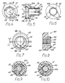
- Figure 4 is an end view of a release tube member;
- Figure 5 is a cross section taken on the line V-V in Figure 4;
- Figure 6 is the other end view of the release tube member, with a portion broken away;
- Figure 7 is an end view of a locking member;
- Figure 8 is a cross section taken on the line VIII-VIII in Figure 7;
- Figure 9 is a cross section taken on the staggered line IX-IX in Figure 1; and
- Figure 10 is a cross section taken on the staggered line X-X in Figure 2.
- Referring to Figures 1 to 3, the self-adjusting cable control device is arranged to be interposed in a cable run (not shown) and comprises a connecting member in the form of a
tubular housing 11 having at one end a cap 10 carrying a cable anchorage crimped in position. A termination member in the form of arod 12 extends through an opening in theother end portion 14 of thetubular housing end 11 which opening serves to locate the termination member rod. The device is connected into a cable run with first and second anchorages (not shown in detail) on the end cap 10 and on thetermination member rod 12. - Clutch means releasably connecting the
tubular housing 11 and therod 12 includecollet members 13 positioned around therod 12 within theend portion 14 of thetubular housing 11. Eachcollet member 13 has a first, external, part frusto-conical surface 15 at one end adapted to engage a complementary, first, internal frusto-conical surface 16 on theend portion 14. A circumferential retaining spring 17 extends circumferentially in alignedgrooves 18 in eachcollet member 14 resiliently to urge thecollet members 13 radially inwardly into contact with thetermination member rod 12. Ahelical spring 19 interposed between acup washer 20 seated on an abutment orshoulder 21 on theend portion 14 and adisc 22 fixed on the end of thetermination member rod 12 resiliently urges thetermination member rod 12 axially inwardly of thehousing 11 and to the right as seen in Figure 1. Eachcollet member 13 is also formed at the end thereof opposite the end having surface 15, with a second, internal, part frusto-conical surface 23, complementary to a second, external, frusto-conical surface 24 on thecup washer 20. The radially inner faces of thecollet members 13 and a portion of therod 12 are circumferentially grooved to form axially spaced, co-acting, 90° triangular profile,serrations conical surfaces 23 of thecollet members 13 with the external frusto-conical surfaces 24 of thecup washer 20 serves to assist thecollet members 13 to disengage from theserrations 12a on the radially inner faces upon relative axial movement occurring as described hereinafter. - As shown in Figures 4 to 6, an axially moveable
release tube member 30 extending through theend portion 14 around thetermination member rod 12 has aninner end portion 32 of cylindrical form having aco-axial bore 31 on axis L₁ and provided with an external,circumferential rib 35, the cylindrical wall being formed withslits 33 to facilitate assembly by enabling therib 35 to be deflected inwardly to be snapped past acircumferential rib 36 on theend portion 14 of the tubular housing to retain thetube member 30 against axially outward movement relative to the end portion whilst allowing limited axial movement. - Circumferentially spaced, axially extending,
external splines 32a on theinner end portion 32 of the release tube member mate with complementaryaxial grooves 14a in theend portion 14 of thehousing 11 to restrain relative rotation between theinner end portion 32 and thehousing 11. Anouter end portion 37 of therelease tube member 30 has a radially outer cylindrical surface 37a co-axial with the axis L₁ of theinner end portion 32 and aneccentric bore 37b with acircumferential groove 38 on an axis L₂ offset from the axis L₁. The base of the eccentric bore is formed with asegmental recess 39 havingradial end faces 39a, 39b. A face 32b on theouter end portion 37 serves to limit movement axially inward of the tubular housing. - As shown in Figures 7 and 8 a
locking member 40 includes aknurled portion 43 and co-axialcentral bore 44 with aneccentric boss 41 having a radially outer cylindrical surface (of diameter equal to that of theeccentric bore 37b) and acircumferential rib 48 with an axis L₁, offset from the axis L₂ of thebore 44. Aprojection 47 is provided on the end face of theboss 42. A partcylindrical projection 45 is provided on the face of thebore 44 and is formed with an axially spaced array of circumferentially extendingserrations 46 complementary to theserrations 12a on therod 12. - The
locking member 40 and therelease tube member 30 are assembled together by pressing theboss 42 on thelocking member 40 into theeccentric bore 37b of therelease tube member 30 such that thecircumferential rib 48 mates with thecircumferential groove 38 and theprojection 47 registers with thesegmental recess 39. Theinner end portion 32 of therelease tube member 30 is then assembled on to theend portion 14 of thehousing 11 by pressing theinner end portion 32 into theend portion 14 and theaxial splines 32a in register withaxial grooves 14a to urge thecircumferential rib 35 on the inner end portion past thecircumferential rib 36 on the end portion, theslits 33 facilitating this operation. - With the
locking member 40, therelease tube member 30 and the tubular housing assembled together, the locking member is rotatable through a restricted arc, which arc is determined by theprojection 47 contacting theradial faces 39a, 39b of therecess 39. Since thelocking member 40 rotates about the axis L₂ offset from the central axis L₁ of the tubular housing, the spacing of thecylindrical projection 45 andserrations 46 from the central axis L₁ is varied with rotation from an unlocked position out of contact with the rod 12 - which thus is free to move axially of the bore 44 - and a locked position in which theserrations 46 fully engage with theserrations 12a on the rod - thereby restraining axial movement of the rod relative to thelocking member 40. Since thelocking member 40 is connected through thecircumferential rib 48 andgroove 38 to therelease tube member 30, which in turn is connected for limited axial movement to thetubular housing 11, relative axial movement between the housing and therod 12 is restrained when thelocking member 40 is rotated to the engaged position other than for a short movement permitted by the spacing of the face 32b and thecircumferential rib 35 on therelease tube member 30 in relation to the location of thecircumferential rib 36 and end face of theend portion 14 of the tubular housing, to facilitate dis-engagement of thecollet members 13 from therod 12. - A convoluted shroud or boot S of elastic material surrounds the
locking member 40 and seats in theend portion 14 of thetubular housing 11 and on therod 13 to provide a seal against dirt, oil and other deleterious matter. - In operation, to install the device into a cable run, the
locking member 40 is rotated into a position indicated in Figures 1, 3 and 9 in which therod 12 passes freely through thebore 44 . Thelocking member 40 and therelease tube member 30 are then urged axially toward thetubular housing 11 to move therelease tube 30 axially into the tubular housing, thereby moving theinner end 50 into contact with thecollet members 13 and, by the inter-action of the sets of frusto-conical surfaces collet members 13 axially and radially out of engagement with theserrations 12a on therod 12. Tension is then applied to therod 12 and thetubular housing 11 to withdraw therod 12 axially from the housing to an extended position and thereby compress thehelical spring 19. With therod 12 at the extended position indicated in Figure 1, thelocking member 40 is rotated to engage theserrations 46 on theportion 45 with theserrations 12a on the rod - by virtue of the eccentricity of the boss 41 - thereby preventing retraction of therod 12 into thetubular housing 11 by the effect of thehelical spring 19. The device is then connected into the slack cable run by attachments (not shown) to thetubular housing 11 androd 12. Having effected attachment, thelocking member 40 is rotated to the original position in which therod 12 passes freely through thebore 44, whereupon the resilience of thehelical spring 19 urges retraction of therod 12 axially into thehousing 11 and applies tension to the cable run. Upon thehelical spring 19 reaching full extension commensurate with the tension in the cable run, at an intermediate position of retraction of therod 12 into thetubular housing 11, the resilience of the circumferential retaining spring 17 is such as to overcome the radial component of the force across theserrations collet members 13 radially inwardly to bring the serrations into engagement, thereby restraining axial movement between thetubular housing 11 and therod 12. Movement of the collet members radially inwardly urges therelease tube member 30 axially outwardly. If, during use, the tension in the cable run falls below the force exerted by thehelical spring 19 to an extent that axial movement of therod 12 relative to thetubular housing 11 brings the frusto-conical faces serrations conical surfaces rod 12 being at an intermediate position of retraction, thecollet members 13 move radially outwardly out of full engagement with the rod so that therespective serrations tubular housing 11. - Since the convoluted shroud or boot S is flexible, rotation of the
locking member 40 can be effected by applying manual pressure through the convoluted shroud or boot adjacent theknurled portion 43 whilst holding thetubular housing 11, so that the convoluted shroud or boot serves at all times to limit ingress of grease or dirt or other deleterious matter into thetubular housing 11. The shroud or boot S also serves to bias thelocking member 40 and therelease tube member 30 away from thetubular housing 11. - It will be appreciated that the serations may be formed as a screw thread rather than axially spaced circumferential grooves.
- It will also be appreciated that whilst the foregoing description envisages the device being connected into a run of core cable, preferably at one end thereof, the device is readily modified to be connected into a run of conduit of a control cable. In such an arrangement the core cable extends centrally through the device and the conduit is connected to the end of the
tubular housing 11 and therod 12, which are made hollow to accommodate the core cable. Alternatively, the conduit in the form of a tightly wound wire spiral, may be substituted for the rod provided strength considerations allows.
Claims (10)
- A control cable adjuster device including a tubular housing (11) having at one end a first anchorage (10) connectable into a cable run and at the other end locating means for a termination member rod (12) resiliently biassed moveably to extend co-axially of the tubular housing (11) between a position fully retracted into, and a position fully extended from, the tubular housing, the termination member rod (12) being formed on the surface thereof with circumferential serrations (12a) engageable with collet means (13) and, on the end thereof remote from the tubular housing, a second anchorage connectable into the cable run, and restraint means provided adjacent a portion of the termination member rod (12) external to the tubular housing (11) moveable between an engaged position in which a portion of the restraint means is engaged with the termination member rod (12), such that relative movement between the termination member rod (12) and the tubular housing (11) is restrained, and a disengaged position in which the restraint means is disengaged from the termination member rod (12), the restraint means including a first member (30) formed with a bore (31) coaxial with the termination member rod (12) through which the termination member rod (12) freely extends and connected into an end portion (14) of the tubular housing (11) in a manner allowing limited axial movement adjacent a shoulder (36) restricting axially outward movement, and a second member (40) having a bore (44) formed with an internal projection (45), the second member and the internal projection being moveable relative to the axis of the termination member rod (12) between the engaged position at which the internal projection (45) engages in the serrations (12a) on the termination member rod (12) and the disengaged position in which the internal projection 45 is radially spaced from the serrations (12a), characterised in that means (32a, 14a) are provided restraining relative rotation between the first member (30) and the housing (11) and that means (38, 48) are provided restraining axial movement of the second member (40) relative to the first member (30) whilst permitting the second member (40) to be rotatable relative to the first member (30) eccentrically in relation to the central axis of the bore (31) in order to move the projection (45) between the engaged position and the disengaged position.
- A control cable adjuster device as claimed in Claim 1, characterised in that the internal projection (45) has a radially inner face of part cylindrical configuration and is formed with an axially spaced array of circumferentially extending serrations (46) complementary to the serrations (12a) on the termination member rod (12).
- A control cable adjuster device as claimed in Claim 1 or Claim 2, characterised in that the second member (40) is formed with an eccentric boss (41) having a radially outer cylindrical surface with an axis (L₁) offset from the axis (L₂) of the central bore (44) of the second member arranged to co-act with an eccentric bore (37b) formed in the first member (30).
- A control cable adjuster device as claimed in Claim 3, characterised in that relative axial movement between the first member (30) and the second member (40) is restrained by means of a circumferential rib (48) formed on one of the members (30,40) co-acting with a circumferential groove (38) formed on the other of the members (30,40).
- A control cable adjuster device as claimed in Claim 3, or Claim 4, characterised in that the relative rotational movement between the first member (30) and the second member (40) is restricted by means of a projection (47) on one of the members (30, 40) co-acting with stops (39a, 39b) formed on the other of the members (30, 40).
- A control cable adjuster device as claimed in any preceding claim, characterised in that the first member (30) is formed with a cylindrical inner end portion (32) arranged to seat in an end portion (14) of the tubular housing 11.
- A control cable adjuster device as claimed in Claim 6, characterised in that the relative axial movement between the first member (30) and the tubular housing (11) is restricted by means of an external circumferential rib (35) formed on the inner end portion (32) of the first member (30) and spaced from a shoulder (32b) on a main portion of the first member (30) co-acting with an inwardly directed circumferential rib (36) on the end portion (14) of the tubular housing (11).
- A control cable adjuster device as claimed in Claim 6 or Claim 7, characterised in that the relative rotational movement between the first member (30) and the tubular housing (11) is restrained by means of axial splines (32a) formed either on the external cylindrical surface of the inner end portion (32) of the first member (30) or on the internal cylindrical surface of the end portion (14) of the tubular housing (11) co-acting with axial grooves (14a) formed respectively either on the inner cylindrical surface of the end portion (14) of the tubular housing (11) or on the external cylindrical surface of the inner end portion (32) of the first member (30).
- A control cable adjuster device as claimed in any preceding Claim, characterised in that the first member (30) is moveable axially of the tubular housing (11) over a restricted distance to contact the collet means (13) and, upon further restricted axial movement, to urge the collet means (13) out of engagement with the serrations (12a) on the termination member rod (12).
- A control cable adjuster device as claimed in any preceding Claim, characterised in that the second member (40) is formed with an enlarged knurled flanged portion (43).
Applications Claiming Priority (2)
| Application Number | Priority Date | Filing Date | Title |
|---|---|---|---|
| US108483 | 1987-10-14 | ||
| US07/108,483 US4753123A (en) | 1987-10-14 | 1987-10-14 | Automatic self adjusting cable control device |
Publications (3)
| Publication Number | Publication Date |
|---|---|
| EP0312382A2 EP0312382A2 (en) | 1989-04-19 |
| EP0312382A3 EP0312382A3 (en) | 1990-01-10 |
| EP0312382B1 true EP0312382B1 (en) | 1992-11-25 |
Family
ID=22322474
Family Applications (1)
| Application Number | Title | Priority Date | Filing Date |
|---|---|---|---|
| EP88309641A Expired - Lifetime EP0312382B1 (en) | 1987-10-14 | 1988-10-14 | Control cable adjuster device |
Country Status (7)
| Country | Link |
|---|---|
| US (1) | US4753123A (en) |
| EP (1) | EP0312382B1 (en) |
| JP (1) | JPH01135910A (en) |
| BR (1) | BR8805265A (en) |
| DE (1) | DE3876208T2 (en) |
| ES (1) | ES2035927T3 (en) |
| PT (1) | PT88748B (en) |
Cited By (1)
| Publication number | Priority date | Publication date | Assignee | Title |
|---|---|---|---|---|
| DE10127630C2 (en) * | 2000-06-13 | 2003-04-30 | Kuester Automotive Control Sys | Device for length adjustment, in particular remote control in motor vehicles |
Families Citing this family (21)
| Publication number | Priority date | Publication date | Assignee | Title |
|---|---|---|---|---|
| US4798100A (en) * | 1987-09-18 | 1989-01-17 | Babcock Industries Inc. | Automatic adjustment device for cable control systems |
| ES2005638A6 (en) * | 1987-10-09 | 1989-03-16 | Pujol & Tarago | Automatic length adjuster for control cables, and control cable provided therewith |
| US4854185A (en) * | 1988-10-17 | 1989-08-08 | Babcock Industries Inc. | Manually operated and locked conduit length adjuster system |
| US5138897A (en) * | 1988-11-23 | 1992-08-18 | Moprod Supra Automotive Limited | Cable adjuster |
| ES2014678A6 (en) * | 1989-06-26 | 1990-07-16 | Pujol & Tarago | Self-adjustable device for clutch control cables |
| US4936161A (en) * | 1989-08-07 | 1990-06-26 | Vdoyazaki Corporation | Cable length adjuster with push and lock attachment |
| US5009122A (en) * | 1990-01-04 | 1991-04-23 | Babcock Industries, Inc. | Sealed cable control system |
| JP3082206B2 (en) * | 1990-03-21 | 2000-08-28 | アイシン精機株式会社 | Variable damping force shock absorber |
| ES2024192A6 (en) * | 1990-04-23 | 1992-02-16 | Pujol & Tarago | Self-regulating device for the length of the security brake cable of motor vehicles. |
| ES2024240A6 (en) * | 1990-05-07 | 1992-02-16 | Pujol & Tarago | Self-adjustment device for adjusting the length of control cables. |
| US5419216A (en) * | 1993-07-22 | 1995-05-30 | Huffy Corporation | Self-adjusting actuation mechanism |
| US5435203A (en) * | 1993-09-16 | 1995-07-25 | Teleflex Incorporated | Manual shift twist adjustor |
| US5653148A (en) | 1995-12-15 | 1997-08-05 | Teleflex Incorporated | Conduit shortening adjustment assembly |
| DE19620496A1 (en) * | 1996-05-21 | 1997-11-27 | Kuester & Co Gmbh | Device for correcting or adjusting the length of cables, control cables or the like |
| US5842552A (en) * | 1996-12-26 | 1998-12-01 | White Consolidated Industries, Inc. | Self-adjusting drive-control cable for a lawn mower |
| ES2140298B1 (en) | 1997-04-23 | 2001-03-01 | Fico Cables Sa | ADJUSTMENT DEVICE FOR CONTROL CABLES. |
| US6308393B1 (en) | 1997-08-14 | 2001-10-30 | Triumph Controls, Inc. | Method of fabricating a terminal mechanism |
| US5913944A (en) | 1997-08-14 | 1999-06-22 | Triumph Controls, Inc. | Cable assembly with telescoping core terminal |
| US6193621B1 (en) | 1999-05-06 | 2001-02-27 | Fanuc Robotics North America, Inc. | Take-up device for tensioning motion transmitting control cables |
| JP4717647B2 (en) * | 2006-01-30 | 2011-07-06 | 株式会社ハイレックスコーポレーション | Adjusting device and control cable with adjusting device |
| CN107914687A (en) * | 2017-11-27 | 2018-04-17 | 重庆长安汽车股份有限公司 | A kind of parking brake cable automatic takeup and automobile |
Family Cites Families (19)
| Publication number | Priority date | Publication date | Assignee | Title |
|---|---|---|---|---|
| DE1166563B (en) * | 1960-07-19 | 1964-03-26 | Teves Kg Alfred | Automatic, mechanical adjustment device for brakes, especially for hand-operated disc brakes |
| GB1068173A (en) * | 1963-02-16 | 1967-05-10 | Girling Ltd | Automatic adjuster for vehicle brakes |
| GB1381281A (en) * | 1971-01-13 | 1975-01-22 | Girling Ltd | Brake adjusters |
| US3942827A (en) * | 1975-03-06 | 1976-03-09 | Societe Anonyme D.B.A. | Mechanical control device for a disc brake |
| DE2652462C2 (en) * | 1975-11-21 | 1985-06-27 | Automotive Products Ltd., Leamington Spa, Warwickshire | Release bearings for vehicle clutches |
| FR2420164A1 (en) * | 1978-03-17 | 1979-10-12 | Ferodo Sa | COMPENSATOR FOR TRANSMISSION LINKAGE |
| US4399894A (en) * | 1979-02-14 | 1983-08-23 | Kelsey-Hayes Company | Push rod slack adjuster |
| US4378713A (en) * | 1980-06-10 | 1983-04-05 | Acco Industries Inc. | Self-adjusting cable control device |
| US4344518A (en) * | 1980-09-22 | 1982-08-17 | Acco Industries Inc. | Self-adjusting cable conduit mechanism |
| DE3143765C2 (en) * | 1980-11-07 | 1987-05-14 | Honda Giken Kogyo K.K., Tokio/Tokyo | Automatic adjustment device for an actuating mechanism with an actuating cable |
| AU531159B2 (en) * | 1980-11-08 | 1983-08-11 | Honda Giken Kogyo Kabushiki Kaisha | Adjusting play in brake control wire |
| IN161423B (en) * | 1983-06-17 | 1987-11-28 | Westinghouse Brake & Signal | |
| GB8400134D0 (en) * | 1984-01-05 | 1984-02-08 | Hoyle E | Cable control operated clutch mechanism |
| US4669330A (en) * | 1984-10-01 | 1987-06-02 | Ford Motor Company | Cable length adjuster |
| US4598809A (en) * | 1985-01-23 | 1986-07-08 | Bwp Controls | Cable-and-sleeve connector |
| FR2577330B1 (en) * | 1985-02-13 | 1987-02-20 | Bendix France | MECHANICAL CONTROL DEVICE WITH SELF-ADJUSTING CABLE |
| FR2617920A2 (en) * | 1985-10-25 | 1989-01-13 | Acco Cables Mans | Device for mechanically controlling a cable with manual adjustment |
| AU584783B2 (en) * | 1986-02-21 | 1989-06-01 | Acco Babcock Inc. | Control cable adjuster device |
| EP0267685B1 (en) * | 1986-10-10 | 1991-03-06 | Babcock Industries Inc. | Control cable adjuster device |
-
1987
- 1987-10-14 US US07/108,483 patent/US4753123A/en not_active Expired - Fee Related
-
1988
- 1988-10-11 JP JP63253959A patent/JPH01135910A/en active Pending
- 1988-10-12 PT PT88748A patent/PT88748B/en not_active IP Right Cessation
- 1988-10-13 BR BR8805265A patent/BR8805265A/en unknown
- 1988-10-14 ES ES198888309641T patent/ES2035927T3/en not_active Expired - Lifetime
- 1988-10-14 EP EP88309641A patent/EP0312382B1/en not_active Expired - Lifetime
- 1988-10-14 DE DE8888309641T patent/DE3876208T2/en not_active Expired - Fee Related
Cited By (1)
| Publication number | Priority date | Publication date | Assignee | Title |
|---|---|---|---|---|
| DE10127630C2 (en) * | 2000-06-13 | 2003-04-30 | Kuester Automotive Control Sys | Device for length adjustment, in particular remote control in motor vehicles |
Also Published As
| Publication number | Publication date |
|---|---|
| EP0312382A3 (en) | 1990-01-10 |
| PT88748A (en) | 1989-07-31 |
| PT88748B (en) | 1993-12-31 |
| DE3876208T2 (en) | 1993-04-01 |
| JPH01135910A (en) | 1989-05-29 |
| BR8805265A (en) | 1989-05-30 |
| DE3876208D1 (en) | 1993-01-07 |
| EP0312382A2 (en) | 1989-04-19 |
| US4753123A (en) | 1988-06-28 |
| ES2035927T3 (en) | 1993-05-01 |
Similar Documents
| Publication | Publication Date | Title |
|---|---|---|
| EP0312382A2 (en) | Control cable adjuster device | |
| EP0286269B1 (en) | Control cable assembly | |
| US5577859A (en) | Arrangement for connecting a rotatable shaft having an end portion with channel toothing formed thereon and a structural component | |
| CA2258808C (en) | Male coupling with moveable threaded segments | |
| US4824281A (en) | Device for connecting a wheel-like body to a shaft | |
| US4751851A (en) | Mechanical cable control device with manual adjustment | |
| US3366405A (en) | Anchorage device | |
| US4798100A (en) | Automatic adjustment device for cable control systems | |
| JPH06507466A (en) | Telescoping splined tubular assembly | |
| US4892004A (en) | Automatic length adjuster for control cables | |
| JPH0226090B2 (en) | ||
| US4955252A (en) | Cable-and-sleeve connections | |
| EP0234864B1 (en) | Control cable adjuster device | |
| US4580665A (en) | Quick connect brake coupling | |
| US5138897A (en) | Cable adjuster | |
| KR19980042648A (en) | Fastener device for restraining vehicle steering wheel to steering shaft | |
| US4639162A (en) | Drawing lock for torque transmitting engagement between two shaft members arrestable in the open position | |
| JPH0338450B2 (en) | ||
| US6652209B2 (en) | Connection element | |
| EP0370685B1 (en) | Cable adjuster | |
| JPS6344108B2 (en) | ||
| JP2533288B2 (en) | Brake piston adjuster mechanism | |
| US4549709A (en) | Device for attaching to a wall the end of a sheath in which a control cable is slidably received | |
| EP0267685B1 (en) | Control cable adjuster device | |
| US5203434A (en) | Mounting structure for cone brake |
Legal Events
| Date | Code | Title | Description |
|---|---|---|---|
| PUAI | Public reference made under article 153(3) epc to a published international application that has entered the european phase |
Free format text: ORIGINAL CODE: 0009012 |
|
| AK | Designated contracting states |
Kind code of ref document: A2 Designated state(s): DE ES FR GB IT |
|
| PUAL | Search report despatched |
Free format text: ORIGINAL CODE: 0009013 |
|
| AK | Designated contracting states |
Kind code of ref document: A3 Designated state(s): DE ES FR GB IT |
|
| 17P | Request for examination filed |
Effective date: 19900321 |
|
| 17Q | First examination report despatched |
Effective date: 19910514 |
|
| GRAA | (expected) grant |
Free format text: ORIGINAL CODE: 0009210 |
|
| ITF | It: translation for a ep patent filed | ||
| AK | Designated contracting states |
Kind code of ref document: B1 Designated state(s): DE ES FR GB IT |
|
| ET | Fr: translation filed | ||
| REF | Corresponds to: |
Ref document number: 3876208 Country of ref document: DE Date of ref document: 19930107 |
|
| REG | Reference to a national code |
Ref country code: ES Ref legal event code: FG2A Ref document number: 2035927 Country of ref document: ES Kind code of ref document: T3 |
|
| PLBE | No opposition filed within time limit |
Free format text: ORIGINAL CODE: 0009261 |
|
| STAA | Information on the status of an ep patent application or granted ep patent |
Free format text: STATUS: NO OPPOSITION FILED WITHIN TIME LIMIT |
|
| PG25 | Lapsed in a contracting state [announced via postgrant information from national office to epo] |
Ref country code: GB Effective date: 19931014 |
|
| PG25 | Lapsed in a contracting state [announced via postgrant information from national office to epo] |
Ref country code: ES Free format text: LAPSE BECAUSE OF EXPIRATION OF PROTECTION Effective date: 19931015 |
|
| 26N | No opposition filed | ||
| GBPC | Gb: european patent ceased through non-payment of renewal fee |
Effective date: 19931014 |
|
| PG25 | Lapsed in a contracting state [announced via postgrant information from national office to epo] |
Ref country code: FR Effective date: 19940630 |
|
| REG | Reference to a national code |
Ref country code: FR Ref legal event code: ST |
|
| PGFP | Annual fee paid to national office [announced via postgrant information from national office to epo] |
Ref country code: DE Payment date: 19980921 Year of fee payment: 11 |
|
| REG | Reference to a national code |
Ref country code: ES Ref legal event code: FD2A Effective date: 19990601 |
|
| PG25 | Lapsed in a contracting state [announced via postgrant information from national office to epo] |
Ref country code: DE Free format text: LAPSE BECAUSE OF NON-PAYMENT OF DUE FEES Effective date: 20000801 |
|
| PG25 | Lapsed in a contracting state [announced via postgrant information from national office to epo] |
Ref country code: IT Free format text: LAPSE BECAUSE OF NON-PAYMENT OF DUE FEES;WARNING: LAPSES OF ITALIAN PATENTS WITH EFFECTIVE DATE BEFORE 2007 MAY HAVE OCCURRED AT ANY TIME BEFORE 2007. THE CORRECT EFFECTIVE DATE MAY BE DIFFERENT FROM THE ONE RECORDED. Effective date: 20051014 |