EP0311707B1 - Color recognition apparatus - Google Patents
Color recognition apparatus Download PDFInfo
- Publication number
- EP0311707B1 EP0311707B1 EP87115033A EP87115033A EP0311707B1 EP 0311707 B1 EP0311707 B1 EP 0311707B1 EP 87115033 A EP87115033 A EP 87115033A EP 87115033 A EP87115033 A EP 87115033A EP 0311707 B1 EP0311707 B1 EP 0311707B1
- Authority
- EP
- European Patent Office
- Prior art keywords
- color
- signal
- recognition apparatus
- pick
- brightness
- Prior art date
- Legal status (The legal status is an assumption and is not a legal conclusion. Google has not performed a legal analysis and makes no representation as to the accuracy of the status listed.)
- Expired - Lifetime
Links
Images


Classifications
-
- G—PHYSICS
- G01—MEASURING; TESTING
- G01J—MEASUREMENT OF INTENSITY, VELOCITY, SPECTRAL CONTENT, POLARISATION, PHASE OR PULSE CHARACTERISTICS OF INFRARED, VISIBLE OR ULTRAVIOLET LIGHT; COLORIMETRY; RADIATION PYROMETRY
- G01J3/00—Spectrometry; Spectrophotometry; Monochromators; Measuring colours
- G01J3/46—Measurement of colour; Colour measuring devices, e.g. colorimeters
- G01J3/50—Measurement of colour; Colour measuring devices, e.g. colorimeters using electric radiation detectors
-
- G—PHYSICS
- G01—MEASURING; TESTING
- G01J—MEASUREMENT OF INTENSITY, VELOCITY, SPECTRAL CONTENT, POLARISATION, PHASE OR PULSE CHARACTERISTICS OF INFRARED, VISIBLE OR ULTRAVIOLET LIGHT; COLORIMETRY; RADIATION PYROMETRY
- G01J3/00—Spectrometry; Spectrophotometry; Monochromators; Measuring colours
- G01J3/46—Measurement of colour; Colour measuring devices, e.g. colorimeters
- G01J2003/466—Coded colour; Recognition of predetermined colour; Determining proximity to predetermined colour
Definitions
- This invention relates to a color recognition apparatus for effectively confirming any color change of a product in a drug production line, an inspection line or the like, and to a process for automatic inspection of foreign matter contamination and of the configuration of such product as well as for efficiently discriminating a color code printed on or attached to articles or goods such as a tire, an electric wire, a food package, and a resistor or the like.
- an optical filter corresponding to the color of the object is mounted on the white-and-black photographic apparatus such as to obtain a difference in density for the purpose of detecting color.
- the problems resulting from this type of apparatus are that much labor is required for treating the object if it has a multiplicity of colors, thus necessitating adjustment of the optical filter each time.
- a form of color recognition which is performed by use of a color photographic apparatus has also been well known.
- This requires color separation in which a color is separated into the three primary colors such as red (R), green (G) and blue (B) and performs a mutual operation for the respective color compositions to obtain color recognition, thereby to departing from (the need for) a sensual decision on the basic of vision.
- This also requires much labor for color correction each time in the color photographic apparatus.
- the (need for a) transmission path for each color composition requires three systems and thus the apparatus is complicated and very costly. It would be desirable to solve these problems.
- various articles such as files, fibers, electrical wires, food packages, and resistors have a multi-colored marking line (stripe, circle, etc.,) printed or attached thereto, this being known as a color code.
- These colored marking lines are different from each other according to the type, grade and the like of the product. In other words, the type, grade and the like of the product may be discerned by identifying the order or arrangement of hues which form these marking lines.
- a well known type of hue detection apparatus for such marking lines and the like employs a color separation light receptive element as disclosed in Japanese Patent Laid-open Nos.80018/1986 and 80019/1986.
- a chroma detection apparatus of the type disclosed is limited to hue detection of only a small part of the hue location of the object the hue of which is to be detected. This type of hue detection apparatus therefore requires to move the object whenever the order or arrangement of hues successively disposed in the form of marking lines is detected so that the portion to be hue detected may be scanned. This requires much time for recognizing the hue of the marking line and leads to shortcomings in that the hue is not discriminated and processed at high speed. It is thus eagerly hoped that this (problem) can be solved.
- the signal components of brightness, chroma and hue are separated from a composite color video signal, preferably NTSC system signals. It is determined whether said separated signals fall within predetermined ranges. If so, a binary output signal is generated indicating that one or more specific hues are contained in the photographed picture.
- a plurality of color pick-up means is provided so as to recognize whether a predetermined plurality of colors are contained in the photographed picture.
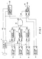
- Fig.1 is a block diagram showing one embodiment of a color recognition apparatus of the invention.
- the color recognition apparatus is adapted for provision in a production line or inspection line and is in use.
- the color recognition apparatus comprises a lens 1 for bringing the object to be inspected into focus with a desired magnification in order to photograph the same; a color television camera 2 for converting the image of the object to be inspected as photographed to a color video signal and for separating the color video signal into a brightness signal Y, a color difference signal (R-Y) between a red signal R and the brightness signal Y, another color difference signal (B-Y) between a blue signal B and the brightness signal Y, a horizontal synchronizing signal HS, and a vertical synchronizing signal VS in order to output these signals; a first setting device 6 for inputting the maximum and minimum values V1 and V2 of a set voltage to a window comparator 3; a second setting device 7 for inputting the maximum and minimum values V3 and V4 of a set voltage to
- the window comparator 3 generates an analogue color difference signal (R-Y) and a binary color difference signal S1 by set voltages V1, V2.
- the window comparator 4 is adapted to generate an analogue color difference signal S2 from the analogue color difference signal (B-Y) and set voltages V3 and V4.
- the window comparator 5 is adapted to generate a binary brightness signal S3 from the analogue brightness signal (Y) and set voltage V5 and V6.
- the binary color difference signals S1 and S2 and the binary brightness signal S3 as generated in the aforementioned manner are inputted to an AND circuit 10 which is adapted to output a control signal S4 when the set ranges of the respective signals correspond to each other.
- the horizontal synchronizing signal HS and vertical synchronizing signal VS from the color television camera 2 are inputted to a synchronous composite circuit 11. These hue signals are synchronously composited to generate a white-and-black video output signal S5 for one frame when the control signal S4 is inputted from the AND circuit 10.
- This white-and-black video output signal S5 is picture processed by means of a picture processing circuit (not shown) such as to display the picture in white-and-black of a hue assigned by the setting devices 6 to 8 on the screen of a white-and-black television monitor.
- the color recognition apparatus is provided with a setting device 9 for inputting the maximum and minimum values V7 and V8 of set voltage to an area decision circuit 12 for the purpose of assigning the dimensions of the object to be inspected, and the area decision circuit 12 into which set voltages V7 and V8 and the vertical synchronizing signal VS are inputted and which is adapted to output a decision signal S6 when the control signal S4 is inputted from the AND circuit 10.
- the decision signal S6 is inputted to a control circuit such as to determine the dimensions of the object to be inspected displayed on the screen of the white-and-black television monitor and to give an alarm or the like if foreign matter of more than a predetermined size is (found to be) mixed therein.
- FIG.2 shows the interrelationship of hues represented by the analogue color difference signals (B-Y), (R-Y) and the brightness signal (Y) outputted from the color television camera 2.
- the color recognition apparatus according to the invention is so arranged that the hue of the object to be inspected that is photographed by the color television camera 2 is expressed by a combination of the analogue color difference signals (B-Y) and (R-Y).
- FIG.2 also shows the situation when the hues are successively expressed in a region in which four conditions are combined.
- the set voltages V1 through V6 are set by the setting devices 6 to 8 for assigning the upper and lower limit values 200A of the analogue color difference signal (B-Y) and the upper and lower limit values 200B of the analogue color difference signal (R-Y), and the upper and lower limit values (not shown) of the brightness signal (Y). It is to be noted that assignment of these hues and comparison of the comparators may be made in a digital manner.
- the operator or user adjusts the lens 1 of the color television camera such as to prepare for photographing the object to be inspected which is being conveyed along the production and inspection lines.
- the hue of the object to be inspected is previously set by setting the set voltages V1 through V6 of the setting devices 6 to 8.
- the object to be inspected is conveyed to a photographing position of the color television camera 2 with the hue designated accordingly, the object to be inspected is photographed by the color television camera 2 for its video (function) to thus separate the brightness signal (Y), color difference signals (B-Y) and (R-Y), the horizontal synchronizing signal HS, and the vertical synchronizing signal VS, inputting these signals to the comparators 3 to 5 and the synchronous composite circuit 11.
- the hue is previouslly assigned by the setting devices 6 to 8, the object to be inspected which is of the same hue as the assigned hue is photographed, and the brightness signal (Y), and the color difference signals (B-Y) and (R-Y) are inputted to the window comparators 3 to 5 so that the binary color difference signals S1 and S2 and the binary brightness signal S3 are generated whereby these signals are inputted to the AND circuit 10.
- the set ranges of the respective signals correspond to each other so that the control signal S4 is inputted to the synchronous composite circuit 11.
- the white-and-black video output signal S5 is generated corresponding to the hue in the aforementioned manner and is then processed by the video processing circuit, the video of the assigned hue being thereby displayed in white and black on the screen of the white-and-black television monitor.
- the dimensions (area) of the object to be inspected are assigned such as to determine the dimensions of any foreign matter mixed therewith
- the dimensions of tolerance of the object to be inspected are assigned by the set voltages V7 and V8, and an alarm or the like is given when the decision signal S6 is generated and inputted to the control circuit when foreign matter occupying more than the assigned area is being conveyed.
- the user is able to carry on product inspection of the object to be inspected by watching the screen of the white-and-black television monitor and responding to any alarm or the lke.
- CCD charge coupled device
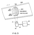
- FIG.3 shows one embodiment in which the color recognition apparatus of the invention is applied to a color code discriminating apparatus which is used in production and inspection lines in a tire manufacturing plant.
- a tire 700 is adapted to be conveyed by a belt conveyor 600 in the direction of the arrow as shown.
- a color code 800 is printed on the periphery of the tire 700 for discriminating the type and grade of the tire 700.
- the color code 800 consists of marking lines 810 (red), 820 (blue), 830 (green), and 840 (yellow).
- the color code discriminating apparatus is mounted in position downwardly of the belt conveyor 600.
- the color code discriminating apparatus comprises a color television camera 22 which is provided with a lens 21 for bringing the color code 800 printed on the tire 700 into focus at a desired magnification for photography and a main body 20 connected to the color television camera 22 by way of a cable 23.
- the color code 800 on the tire 700 which has been conveyed by the belt conveyor 600 is photographed by the color television camera 22 and is inputted to the main body 20, and is then video processed. In this manner, the type and grade of the tire 700 are discriminated in order of the hues of the marking lines 810 to 840 of the color code 800.
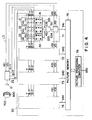
- FIG.4 is a block diagram showing one form of a circuit arrangement of a color code discriminating apparatus.
- the color television camera 22 is actuated to convert the picture of the color code 800 photographed as aforementioned to the color video signal and to then separate the color video signal into the brightness signal Y, the color difference signal (R-Y) between the red signal R and the brightness signal Y , the color difference signal (B-Y) between the blue signal B and the brightness signal Y, the horizontal synchronizing signal HS1, and the vertical synchronizing signal VS1 for inputting these signals.
- the main body 20 of the apparatus comprises color pick-up means 71 to 74 for electrically picking up information on each of the hues of the marking lines preassigned such as to output binary video signals S41 to S44, a picture memory 75 for storing the binary picture signals S41 to S44 as the picture data, and a picture processing computer 76 for reading out the picture data stored in the picture memory 75 such as to compare the data with the order or arrangement of the hues of the preassigned marking lines to discriminate the data, thereby to output a discriminating signal S50.
- each pick-up means is identical, it is deemed sufficient to describe only one, that is, the pick-up means 71.
- the color pick-up means 71 is provided therein with a setting device 31 for inputting the maximum and minimum values V11 and V21 of the set voltage to a window comparator 41, a second setting device 32 for inputting the maximum and minimum values V31 and V41 of the set voltage to a second window comparator 42, and a third setting device 33 for inputting the maximum and minimum values V51 and V61 of the set voltage to a third window comparator 43.
- the first window comparator 41 is adapted to produce a binary color difference signal S31 from the analog color difference signal (R-Y) and the set voltages V11 and V21
- the second window comparator 42 is adapted to generate a binary color difference signal S32 from the analog color difference signal (B-Y) and the set voltages V31 and V41
- the third comparator 43 is adapted to produce a binary brightness signal S33 from the analog brightness signal (Y) and the set voltages V51 and V61.
- the binary color difference signals S31 and S32 and the binary brightness signal S33 as generated in the aforementioned manner are inputted to an "AND" circuit 50 such as to output a control signal S34 when set ranges of the respective signals correspond to each other.
- the horizontal and vertical synchronizing signals HS1 and VS1 from the color television camera 22 are inputted to a synchronous composite circuit 60 which is adapted to synchronously compose these signals when the control signal S34 from the "AND" circuit 50 is inputted, thus producing a binary video signal S41.
- the user or operator initially adjusts the lens 21 of the color television camera 22 to make preparation for photographing the color code 800 on the tire 700 conveyed by the belt conveyor 600 in the production and inspection lines.
- the hues of the marking lines 810 to 840 as the color code 800 are set by setting the set voltage V of the setting device disposed on each of the color pick-up means 71 to 74. For instance, red, blue, green and yellow of the marking lines 810, 820, 830 and 840 are assigned to the color pick-up means 71, 72, 73 and 74, respectively.
- the hues of the marking lines 810 to 840 are set in the order of colors such as red, blue, green and yellow to the picture processing computer 76.
- the videos of the color code 800 of the tire 700 are photographed such as to separate the signals into the brightness, color difference signals (Y), (B-Y) and (R-Y), and horizontal, vertical synchronizing signals HS1 and VS1, thereby inputting these signals to the respective color pick-up means 71 to 74 when the tire 700 is conveyed to a position of photographing of the color television camera 22.
- the binary color difference signal and the binary brightness signal are generated and inputted to the "AND" circuit when the brightness signal (Y) and the color difference signals (B-Y) and (R-Y) of the marking lines 810 to 840 are inputted to the comparators, and the control signal is in turn inputted to the synchronous composite circuit when the set ranges of the respective signals correspond to each other.
- the binary picture signals S41 to S44 which correspond to the hues of the marking lines 810 to 840 are generated from the color pick-up means 71 to 74 and once stored as the video data in the picture memory 75.
- These video signals S41 to S44 are then inputted to the picture processing computer 76 such as to discriminate the order (red, blue, green and yellow) of the hues of the marking lines 810 to 840 as above set, thereby outputting the discriminating signal S50.
- a control device and the like is connected to the output side of the main body 26 to readily discriminate the quality, grade and the like of the tire 700.
- the invention has been described with reference to the instance where the object to be inspected is photographed by the color television camera, it is apparent that this may be done by the use of a photographic apparatus such as a charge coupled device (CCD) camera.
- CCD charge coupled device
- the number of the color pick-up means may be increased depending upon varieties of the hues of the color codes.
- the invention has been described with reference to the tire as the object to be inspected, it is obvious that the color codes printed on or attached to all the products such as a wire, food packages, and resistors and the like may be discriminated by the use of the color code discriminating apparatus.
- FIG.5 is a block diagram showing another embodiment of the color recognition apparatus according to the invention.
- the color recognition apparatus is mounted in a production line, an inspection line and the like for use therein and comprises a lens 81 for bringing the object to be inspected into focus at a desired magnification to photograph the object, on an NTSC system color television camera 82 for outputting a composite color video signal ES of the picture of the object to be inspected as photographed, and a synchronizing separator circuit 98 for separating the composite color video signal ES into a horizontal synchronizing signal HS2 and a vertical synchronizing signal VS2 to output the same.
- the color recognition apparatus further comprises a trap circuit 83 for eliminating a component of a chrominance signal included in the composite color video signal ES to separate the brightness signal Y, a band pass filter circuit 84 for separating only a chrominance signal component S61 from the composite color video signal ES, an amplitude detection circuit 85 for separating only an amplitude component S62 of the chrominance signal component S61 from the band pass filter circuit 84, a synchronous oscillation circuit 86 for effecting an oscillation synchronously with a burst signal from the same contained in the composite color video signal ES to reproduce a subcarrier S63, and a phase shift detector circuit 87 for detecting a phase difference in the chrominance signal component S61 from the band pass filter circuit 84 as referenced from the subcarrier S63 so that a signal S64 corresponding to the hue may be detected.
- a trap circuit 83 for eliminating a component of a chrominance signal included in the composite color video signal ES to separate the brightness signal Y
- a setting device 88 for inputting the maximum and minimum values V71 and V72 of a set voltage to a window comparates 92
- a setting device 89 for inputting the maximum and minimum values V73 and V74 of a set voltage to a window comparator 83
- a setting device 90 for inputting the maximum and minimum values V75 and V76 of a set voltage to a window comparator 94.
- the window comparator 92 is adapted to generate a binary lightness signal component S65 from the brightness signal Y and the set voltage V71 and V72
- the window comparator 93 is adapted to generate a binary chroma signal component S66 from the amplitute component S62 and the set voltages V73 and V74
- the window comparator 94 is adapted to produce a binary hue signal component S67 from the signal corresponding to the hue and the set voltages V75 and V76.
- the binary chroma signal component S66 and the binary hue signal component S67 as generated in the aforementioned manner are input to an "AND" circuit 95 which is adapted to output a control signal S68 when the set ranges of the respective signals correspond to each other.
- the color recognition apparatus is provided with a synchronous composite circuit 96 for synchronously compose the horizontal and vertical synchronous signals HS2 and VS2 to generate a white-and-black video output signal S69 for one frame when these synchronous signals from the synchronizing separator circuit 98 and then the control signal S68 are inputted.
- the white-and-black video output signal S69 is picture processed by a picture processing circuit (not shown) to display on the screen of the white-and-black television monitor the picture in white-and-black of a color of the object to be inspected, as assigned by the setting devices 68 to 90.
- the color recognition apparatus further includes a setting device 91 for inputting the maximum and minimum values V77 and V78 of a set voltage to an area decision circuit 97 for the purpose of assigning dimensions of the object to be inspected, and the area decision circuit 97 to which the set voltages V77 and V78 and the vertical synchronizing signal VS2 are inputted and which is adapted to output a decision signal S70 when the control signal S68 is inputted from the "AND" circuit 95.
- the area dicision circuit is adapted to input the decision signal S70 to a control circuit (not shown) to make a decision of dimensions of the object to be inspected, which is to be displayed in the screen of the white-and-black television monitor, thereby giving an alarm or the like when foreign matter of dimensions more than those as predetermined is mixed in.
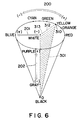
- FIG.6 is a graphic presentation showing an interrelationship between three attributes such as a hue, chroma and lightness obtained by the color recognition apparatus of the invention.
- the color recognition apparatus according to the invention is intended to express any color of the object to be inspected, which is photographed by the television camera 2 in combination of the hue with chroma and lightness.
- the colors may be discriminated in a manner likely to be most similar to the eyesight.
- the colors such as red, orange, yellow, green, cyan, blue and purple are clockwise juxtaposed on the circumference of a circle with white as the center of a circle in the order of wavelength. All the hues as well as the lightest color of different chroma are represented on the circumference.
- An arrow 200 is shown as indicative of the hue of wavelength which is rightward (+) longer but leftward (-) shorter.
- a further arrow 201 is shown as indicative of chroma which is leftward (+) higher but rightward (-) lower.
- Another arrow 202 is shown as representative of lightness which is high when brightness is high (+) and which is gray when brightness is low (-) but black when brightness is zero.
- variations in lightness is represented in the axis of ordinate to obtain a cone, as shown, with a disc indicative of lightness as the base and with black as the apex. All the colors are contained in the cone.
- a color 301 comprises all the lightest yellows with different chroma, which are arranged in such a manner that the clearest yellow 310, whitely yellow 312, and yellowish white 313 are lined up on yellow and white line. Variations in lightness of these colors are shown as being positioned in any of points on a triangle encompassed by white, black and yellow.
- the color recognition apparatus is designed to set brightness by the set voltages V71 and V72 of the setting device 88, chroma by the set voltages V73 and V74 of the setting device 89, and hue by the set voltages V75 and V76 of the setting device 90.
- the manner in which the color recognition apparatus is operated will be explained hereinafter.
- the user or operator initially adjusts the lens 81 of the color television camera 82 to prepare for photographing the object to be inspected conveyed to the production line, the inspection line and the like.
- the color of the object to be inspected is assigned by setting the set voltages V71 to V76 of the setting devices 88 to 90 in the manner as aforementioned.
- the video of the object to be inspected when it is conveyed with the color designated accordingly, is photographed by the color television camera to thus make the composite color video signal ES, the horizontal synchronizing signal VS2 separable so that the composite color video signal ES is inputted to the trap circuit 83 to render the brightness signal Y separable.
- the composite color video signal ES is separated by the band pass filter circuit 84 as the chrominance signal component S61, making the amplitude component S62 separable by the amplitude detection circuit 85.
- the composite color video signal ES is reproduced as the subcarrier S63 by means of the synchronous oscillation circuit 86.
- the subcarrier S63 and the chrominance signal component S61 are detected by the phase shift detector circuit 87 as the signal S64 corresponding to the hue.
- the brightness signal Y, the amplitude component S62, and the signal S64 corresponding to the hue are inputted to the respective window comparators 92 to 94.
- the horizontal and vertical synchronizing signals HS2 and VS2 are inputted to the synchronous composite circuit 96 in the manner as aforementioned, these signals are composed to generate the binary white-and-black video output signal S69 which is processed by the picture processing circuit, and the picture of assigned color is displayed in white-and-black on the screen of the white-and-black television monitor.
- the dimensions (area) of the object to be ispected are assigned such as to determine the dimensions of any foreign matter mixed therewith
- the dimensions of tolerance of the object to be inspected are assigned by the set voltages V77 and V78, and an alarm or the like is given if the dicision signal S60 is generated and inputted to the control circuit when foreign matter occupying more than the assigned area is being conveyed.
- the user is able to carry on product inspection of the object to be inspected by (watching) the screen of the white-and-black television monitor and responding to any alarm or the like.
- a window may be set for display made by a display apparatus to limit or modify a region to be displayed.
Landscapes
- Physics & Mathematics (AREA)
- Spectroscopy & Molecular Physics (AREA)
- General Physics & Mathematics (AREA)
- Image Processing (AREA)
- Investigating Materials By The Use Of Optical Means Adapted For Particular Applications (AREA)
- Testing, Inspecting, Measuring Of Stereoscopic Televisions And Televisions (AREA)
- Processing Of Color Television Signals (AREA)
- Image Analysis (AREA)
Description
- This invention relates to a color recognition apparatus for effectively confirming any color change of a product in a drug production line, an inspection line or the like, and to a process for automatic inspection of foreign matter contamination and of the configuration of such product as well as for efficiently discriminating a color code printed on or attached to articles or goods such as a tire, an electric wire, a food package, and a resistor or the like.
- It has heretofore been customary to check for color changes of products and to inspect whether foreign matter has been mixed therewith by means of a method employing the naked eye of the operator so as to ensure the quality of products in a drug production line, inspection line or the like. There are difficulties involved in such visual inspection, however, since uniform color discrimination cannot be made and the operator may not be instantaneously aware of the presence of foreign matter to allow for removal thereof due to individual differences.
- There has been a well known white-and-black photographic apparatus that is adapted to obtain the video of an object and then to picture process the video signal obtained from a picture treatment with the density of the video, that is, differences in lightness, thereby allowing a hue to be identified. An apparatus of this class is not capable of color discrimination when there is no difference in lightness even if the hue of the object is different.
- For this reason, an optical filter corresponding to the color of the object is mounted on the white-and-black photographic apparatus such as to obtain a difference in density for the purpose of detecting color. The problems resulting from this type of apparatus are that much labor is required for treating the object if it has a multiplicity of colors, thus necessitating adjustment of the optical filter each time.
- A form of color recognition which is performed by use of a color photographic apparatus has also been well known. This requires color separation in which a color is separated into the three primary colors such as red (R), green (G) and blue (B) and performs a mutual operation for the respective color compositions to obtain color recognition, thereby to departing from (the need for) a sensual decision on the basic of vision. This also requires much labor for color correction each time in the color photographic apparatus. In addition, the (need for a) transmission path for each color composition requires three systems and thus the apparatus is complicated and very costly. It would be desirable to solve these problems.
- In these days, various articles such as files, fibers, electrical wires, food packages, and resistors have a multi-colored marking line (stripe, circle, etc.,) printed or attached thereto, this being known as a color code. These colored marking lines are different from each other according to the type, grade and the like of the product. In other words, the type, grade and the like of the product may be discerned by identifying the order or arrangement of hues which form these marking lines.
- A well known type of hue detection apparatus for such marking lines and the like employs a color separation light receptive element as disclosed in Japanese Patent Laid-open Nos.80018/1986 and 80019/1986. A chroma detection apparatus of the type disclosed is limited to hue detection of only a small part of the hue location of the object the hue of which is to be detected. This type of hue detection apparatus therefore requires to move the object whenever the order or arrangement of hues successively disposed in the form of marking lines is detected so that the portion to be hue detected may be scanned. This requires much time for recognizing the hue of the marking line and leads to shortcomings in that the hue is not discriminated and processed at high speed. It is thus eagerly hoped that this (problem) can be solved.
- It is an object of the invention to provide a color recognition apparatus wherein a color difference signal is separated from a brightness signal by a signal representing a video photographed by means of a color television camera or the like, and wherein determination is made as to whether or not these signals fall within a predetermined region, and wherein a binary signal is outputted under the condition that all the signals fall within the predetermined region so that a binary (white and black) signal of the assigned specific hue may be obtained such as to allow the hue to be automatically recognized, the binary image signal thus outputted being subjected to image processing by means of an image processing computer, whereby the order or arrangement of the marking lines for each hue may be discriminated at high speed.
- The above object is achieved by providing a color recognition apparatus including the features defined in the patent claims. According to a first embodiment, the signal components of brightness, chroma and hue are separated from a composite color video signal, preferably NTSC system signals. It is determined whether said separated signals fall within predetermined ranges. If so, a binary output signal is generated indicating that one or more specific hues are contained in the photographed picture.
- According to a further embodiment, a plurality of color pick-up means is provided so as to recognize whether a predetermined plurality of colors are contained in the photographed picture.
- The nature, principle and utility of this invention will become more apparent from the following description when read in conjunction with the accompanying drawings.
- In the accompanying drawings:
- FIG.1 is a block diagram of a color recognition apparatus, one embodiment of the present invention;
- FIG.2 is a graph showing the mutual relationship of hues representative of a color difference signal (B-Y) and a brightness signal (Y);
- FIG.3 is a view showing an applied example of a color code discrimination apparatus in which the invention is embodied;
- FIG.4 is a block diagram showing a circuit arrangement for a color code discriminating apparatus;
- FIG.5 is a block diagram of a color recognition apparatus, another embodiment of the present invention; and
- FIG.6 is a graphic presentation showing the interrelation of such attributes as hue, chroma and lightness in the color recognition apparatus of the invention.
- Fig.1 is a block diagram showing one embodiment of a color recognition apparatus of the invention. The color recognition apparatus is adapted for provision in a production line or inspection line and is in use. The color recognition apparatus comprises a lens 1 for bringing the object to be inspected into focus with a desired magnification in order to photograph the same; a
color television camera 2 for converting the image of the object to be inspected as photographed to a color video signal and for separating the color video signal into a brightness signal Y, a color difference signal (R-Y) between a red signal R and the brightness signal Y, another color difference signal (B-Y) between a blue signal B and the brightness signal Y, a horizontal synchronizing signal HS, and a vertical synchronizing signal VS in order to output these signals; afirst setting device 6 for inputting the maximum and minimum values V₁ and V₂ of a set voltage to awindow comparator 3; asecond setting device 7 for inputting the maximum and minimum values V₃ and V₄ of a set voltage to a second window comparator 4; and athird setting device 8 for inputting the maximum and minimum values V₅ and V₆ of a set voltage to athird window comparator 5. In this instance, thewindow comparator 3 generates an analogue color difference signal (R-Y) and a binary color difference signal S1 by set voltages V₁, V₂. The window comparator 4 is adapted to generate an analogue color difference signal S2 from the analogue color difference signal (B-Y) and set voltages V₃ and V₄. Thewindow comparator 5 is adapted to generate a binary brightness signal S3 from the analogue brightness signal (Y) and set voltage V₅ and V₆. - The binary color difference signals S1 and S2 and the binary brightness signal S3 as generated in the aforementioned manner are inputted to an
AND circuit 10 which is adapted to output a control signal S4 when the set ranges of the respective signals correspond to each other. The horizontal synchronizing signal HS and vertical synchronizing signal VS from thecolor television camera 2 are inputted to a synchronous composite circuit 11. These hue signals are synchronously composited to generate a white-and-black video output signal S5 for one frame when the control signal S4 is inputted from theAND circuit 10. This white-and-black video output signal S5 is picture processed by means of a picture processing circuit (not shown) such as to display the picture in white-and-black of a hue assigned by thesetting devices 6 to 8 on the screen of a white-and-black television monitor. The color recognition apparatus is provided with asetting device 9 for inputting the maximum and minimum values V₇ and V₈ of set voltage to anarea decision circuit 12 for the purpose of assigning the dimensions of the object to be inspected, and thearea decision circuit 12 into which set voltages V₇ and V₈ and the vertical synchronizing signal VS are inputted and which is adapted to output a decision signal S6 when the control signal S4 is inputted from theAND circuit 10. The decision signal S6 is inputted to a control circuit such as to determine the dimensions of the object to be inspected displayed on the screen of the white-and-black television monitor and to give an alarm or the like if foreign matter of more than a predetermined size is (found to be) mixed therein. - FIG.2 shows the interrelationship of hues represented by the analogue color difference signals (B-Y), (R-Y) and the brightness signal (Y) outputted from the
color television camera 2. The color recognition apparatus according to the invention is so arranged that the hue of the object to be inspected that is photographed by thecolor television camera 2 is expressed by a combination of the analogue color difference signals (B-Y) and (R-Y). FIG.2 also shows the situation when the hues are successively expressed in a region in which four conditions are combined. As shown, there are instances where magenta is obtained when the analogue color difference signal is ( B-Y > 0, R-Y > 0) , where red and yellow are given when the analogue color difference signal is ( B-Y < 0, R-Y > 0), where blue and cyan are obtained when the analogue color difference signal is ( B-Y > 0, R-Y < 0), where green is given when the analogue color difference signal is ( B-Y < 0, R-Y < 0), and where gray is obtained when the analogue color difference signal is ( R-Y = 0, R-Y = 0 ). In this connection, for instance, for designation of ahue 300, the set voltages V₁ through V₆ are set by thesetting devices 6 to 8 for assigning the upper andlower limit values 200A of the analogue color difference signal (B-Y) and the upper andlower limit values 200B of the analogue color difference signal (R-Y), and the upper and lower limit values (not shown) of the brightness signal (Y). It is to be noted that assignment of these hues and comparison of the comparators may be made in a digital manner. - The manner of use of this color recognition apparatus will now be explained. First, the operator or user adjusts the lens 1 of the color television camera such as to prepare for photographing the object to be inspected which is being conveyed along the production and inspection lines. As above mentioned, the hue of the object to be inspected is previously set by setting the set voltages V₁ through V₆ of the
setting devices 6 to 8. In this manner, when the object to be inspected is conveyed to a photographing position of thecolor television camera 2 with the hue designated accordingly, the object to be inspected is photographed by thecolor television camera 2 for its video (function) to thus separate the brightness signal (Y), color difference signals (B-Y) and (R-Y), the horizontal synchronizing signal HS, and the vertical synchronizing signal VS, inputting these signals to thecomparators 3 to 5 and the synchronous composite circuit 11. It is to be noted that since the hue is previouslly assigned by thesetting devices 6 to 8, the object to be inspected which is of the same hue as the assigned hue is photographed, and the brightness signal (Y), and the color difference signals (B-Y) and (R-Y) are inputted to thewindow comparators 3 to 5 so that the binary color difference signals S1 and S2 and the binary brightness signal S3 are generated whereby these signals are inputted to theAND circuit 10. At this moment, the set ranges of the respective signals correspond to each other so that the control signal S4 is inputted to the synchronous composite circuit 11. The white-and-black video output signal S5 is generated corresponding to the hue in the aforementioned manner and is then processed by the video processing circuit, the video of the assigned hue being thereby displayed in white and black on the screen of the white-and-black television monitor. - Now, when the dimensions (area) of the object to be inspected are assigned such as to determine the dimensions of any foreign matter mixed therewith, the dimensions of tolerance of the object to be inspected are assigned by the set voltages V₇ and V₈, and an alarm or the like is given when the decision signal S6 is generated and inputted to the control circuit when foreign matter occupying more than the assigned area is being conveyed. In this manner, the user is able to carry on product inspection of the object to be inspected by watching the screen of the white-and-black television monitor and responding to any alarm or the lke.
- Although an instance where the object to be inspected is photographed by a color television camera has been described, a photographic apparatus such as a charge coupled device ( CCD ) camera may also be employed.
- FIG.3 shows one embodiment in which the color recognition apparatus of the invention is applied to a color code discriminating apparatus which is used in production and inspection lines in a tire manufacturing plant.
- In these production and inspection lines, a
tire 700 is adapted to be conveyed by abelt conveyor 600 in the direction of the arrow as shown. Acolor code 800 is printed on the periphery of thetire 700 for discriminating the type and grade of thetire 700. Thecolor code 800 consists of marking lines 810 (red), 820 (blue), 830 (green), and 840 (yellow). The color code discriminating apparatus is mounted in position downwardly of thebelt conveyor 600. The color code discriminating apparatus comprises acolor television camera 22 which is provided with alens 21 for bringing thecolor code 800 printed on thetire 700 into focus at a desired magnification for photography and amain body 20 connected to thecolor television camera 22 by way of acable 23. Thecolor code 800 on thetire 700 which has been conveyed by thebelt conveyor 600 is photographed by thecolor television camera 22 and is inputted to themain body 20, and is then video processed. In this manner, the type and grade of thetire 700 are discriminated in order of the hues of the markinglines 810 to 840 of thecolor code 800. - FIG.4 is a block diagram showing one form of a circuit arrangement of a color code discriminating apparatus. The
color television camera 22 is actuated to convert the picture of thecolor code 800 photographed as aforementioned to the color video signal and to then separate the color video signal into the brightness signal Y, the color difference signal (R-Y) between the red signal R and the brightness signal Y , the color difference signal (B-Y) between the blue signal B and the brightness signal Y, the horizontal synchronizing signal HS1, and the vertical synchronizing signal VS1 for inputting these signals. Themain body 20 of the apparatus comprises color pick-up means 71 to 74 for electrically picking up information on each of the hues of the marking lines preassigned such as to output binary video signals S41 to S44, apicture memory 75 for storing the binary picture signals S41 to S44 as the picture data, and apicture processing computer 76 for reading out the picture data stored in thepicture memory 75 such as to compare the data with the order or arrangement of the hues of the preassigned marking lines to discriminate the data, thereby to output a discriminating signal S50. - Now, the color pick-up means 71 to 74 will be detailed. Since each pick-up means is identical, it is deemed sufficient to describe only one, that is, the pick-up means 71.
- The color pick-up means 71 is provided therein with a
setting device 31 for inputting the maximum and minimum values V₁₁ and V₂₁ of the set voltage to awindow comparator 41, asecond setting device 32 for inputting the maximum and minimum values V₃₁ and V₄₁ of the set voltage to asecond window comparator 42, and athird setting device 33 for inputting the maximum and minimum values V₅₁ and V₆₁ of the set voltage to athird window comparator 43. It is noted that thefirst window comparator 41 is adapted to produce a binary color difference signal S31 from the analog color difference signal (R-Y) and the set voltages V₁₁ and V₂₁, and that thesecond window comparator 42 is adapted to generate a binary color difference signal S32 from the analog color difference signal (B-Y) and the set voltages V₃₁ and V₄₁, and that thethird comparator 43 is adapted to produce a binary brightness signal S33 from the analog brightness signal (Y) and the set voltages V₅₁ and V₆₁. - The binary color difference signals S31 and S32 and the binary brightness signal S33 as generated in the aforementioned manner are inputted to an "AND"
circuit 50 such as to output a control signal S34 when set ranges of the respective signals correspond to each other. The horizontal and vertical synchronizing signals HS1 and VS1 from thecolor television camera 22 are inputted to a synchronouscomposite circuit 60 which is adapted to synchronously compose these signals when the control signal S34 from the "AND"circuit 50 is inputted, thus producing a binary video signal S41. - How to use the color code discriminating apparatus will be explained. The user or operator initially adjusts the
lens 21 of thecolor television camera 22 to make preparation for photographing thecolor code 800 on thetire 700 conveyed by thebelt conveyor 600 in the production and inspection lines. The hues of the markinglines 810 to 840 as thecolor code 800 are set by setting the set voltage V of the setting device disposed on each of the color pick-up means 71 to 74. For instance, red, blue, green and yellow of the markinglines lines 810 to 840 are set in the order of colors such as red, blue, green and yellow to thepicture processing computer 76. Then, in this manner, the videos of thecolor code 800 of thetire 700 are photographed such as to separate the signals into the brightness, color difference signals (Y), (B-Y) and (R-Y), and horizontal, vertical synchronizing signals HS1 and VS1, thereby inputting these signals to the respective color pick-up means 71 to 74 when thetire 700 is conveyed to a position of photographing of thecolor television camera 22. - In this connection, it is noted that since the hues are assigned to the setting devices of the color pick-up means 71 to 74, the binary color difference signal and the binary brightness signal are generated and inputted to the "AND" circuit when the brightness signal (Y) and the color difference signals (B-Y) and (R-Y) of the marking
lines 810 to 840 are inputted to the comparators, and the control signal is in turn inputted to the synchronous composite circuit when the set ranges of the respective signals correspond to each other. In the manner as aforementioned, the binary picture signals S41 to S44 which correspond to the hues of the markinglines 810 to 840 are generated from the color pick-up means 71 to 74 and once stored as the video data in thepicture memory 75. These video signals S41 to S44 are then inputted to thepicture processing computer 76 such as to discriminate the order (red, blue, green and yellow) of the hues of the markinglines 810 to 840 as above set, thereby outputting the discriminating signal S50. Now, a control device and the like is connected to the output side of the main body 26 to readily discriminate the quality, grade and the like of thetire 700. - Although the invention has been described with reference to the instance where the object to be inspected is photographed by the color television camera, it is apparent that this may be done by the use of a photographic apparatus such as a charge coupled device (CCD) camera. The number of the color pick-up means may be increased depending upon varieties of the hues of the color codes. Although the invention has been described with reference to the tire as the object to be inspected, it is obvious that the color codes printed on or attached to all the products such as a wire, food packages, and resistors and the like may be discriminated by the use of the color code discriminating apparatus.
- FIG.5 is a block diagram showing another embodiment of the color recognition apparatus according to the invention. The color recognition apparatus is mounted in a production line, an inspection line and the like for use therein and comprises a
lens 81 for bringing the object to be inspected into focus at a desired magnification to photograph the object, on an NTSC systemcolor television camera 82 for outputting a composite color video signal ES of the picture of the object to be inspected as photographed, and a synchronizingseparator circuit 98 for separating the composite color video signal ES into a horizontal synchronizing signal HS2 and a vertical synchronizing signal VS2 to output the same. The color recognition apparatus further comprises atrap circuit 83 for eliminating a component of a chrominance signal included in the composite color video signal ES to separate the brightness signal Y, a bandpass filter circuit 84 for separating only a chrominance signal component S61 from the composite color video signal ES, anamplitude detection circuit 85 for separating only an amplitude component S62 of the chrominance signal component S61 from the bandpass filter circuit 84, asynchronous oscillation circuit 86 for effecting an oscillation synchronously with a burst signal from the same contained in the composite color video signal ES to reproduce a subcarrier S63, and a phaseshift detector circuit 87 for detecting a phase difference in the chrominance signal component S61 from the bandpass filter circuit 84 as referenced from the subcarrier S63 so that a signal S64 corresponding to the hue may be detected. - There is also provided a
setting device 88 for inputting the maximum and minimum values V₇₁ and V₇₂ of a set voltage to awindow comparates 92, asetting device 89 for inputting the maximum and minimum values V₇₃ and V₇₄ of a set voltage to awindow comparator 83, and asetting device 90 for inputting the maximum and minimum values V₇₅ and V₇₆ of a set voltage to awindow comparator 94. In this instance, it is noted that thewindow comparator 92 is adapted to generate a binary lightness signal component S65 from the brightness signal Y and the set voltage V₇₁ and V₇₂, and that thewindow comparator 93 is adapted to generate a binary chroma signal component S66 from the amplitute component S62 and the set voltages V₇₃ and V₇₄, and that thewindow comparator 94 is adapted to produce a binary hue signal component S67 from the signal corresponding to the hue and the set voltages V₇₅ and V₇₆. The binary chroma signal component S66 and the binary hue signal component S67 as generated in the aforementioned manner are input to an "AND"circuit 95 which is adapted to output a control signal S68 when the set ranges of the respective signals correspond to each other. - The color recognition apparatus is provided with a synchronous
composite circuit 96 for synchronously compose the horizontal and vertical synchronous signals HS2 and VS2 to generate a white-and-black video output signal S69 for one frame when these synchronous signals from the synchronizingseparator circuit 98 and then the control signal S68 are inputted. The white-and-black video output signal S69 is picture processed by a picture processing circuit (not shown) to display on the screen of the white-and-black television monitor the picture in white-and-black of a color of the object to be inspected, as assigned by the setting devices 68 to 90. - The color recognition apparatus further includes a
setting device 91 for inputting the maximum and minimum values V₇₇ and V₇₈ of a set voltage to anarea decision circuit 97 for the purpose of assigning dimensions of the object to be inspected, and thearea decision circuit 97 to which the set voltages V₇₇ and V₇₈ and the vertical synchronizing signal VS2 are inputted and which is adapted to output a decision signal S70 when the control signal S68 is inputted from the "AND"circuit 95. The area dicision circuit is adapted to input the decision signal S70 to a control circuit (not shown) to make a decision of dimensions of the object to be inspected, which is to be displayed in the screen of the white-and-black television monitor, thereby giving an alarm or the like when foreign matter of dimensions more than those as predetermined is mixed in. - FIG.6 is a graphic presentation showing an interrelationship between three attributes such as a hue, chroma and lightness obtained by the color recognition apparatus of the invention. The color recognition apparatus according to the invention is intended to express any color of the object to be inspected, which is photographed by the
television camera 2 in combination of the hue with chroma and lightness. In other words, the colors may be discriminated in a manner likely to be most similar to the eyesight. As shown, the colors such as red, orange, yellow, green, cyan, blue and purple are clockwise juxtaposed on the circumference of a circle with white as the center of a circle in the order of wavelength. All the hues as well as the lightest color of different chroma are represented on the circumference. Anarrow 200 is shown as indicative of the hue of wavelength which is rightward (+) longer but leftward (-) shorter. Afurther arrow 201 is shown as indicative of chroma which is leftward (+) higher but rightward (-) lower. Anotherarrow 202 is shown as representative of lightness which is high when brightness is high (+) and which is gray when brightness is low (-) but black when brightness is zero. Now, variations in lightness is represented in the axis of ordinate to obtain a cone, as shown, with a disc indicative of lightness as the base and with black as the apex. All the colors are contained in the cone. For instance, acolor 301 comprises all the lightest yellows with different chroma, which are arranged in such a manner that the clearest yellow 310, whitely yellow 312, and yellowish white 313 are lined up on yellow and white line. Variations in lightness of these colors are shown as being positioned in any of points on a triangle encompassed by white, black and yellow. When these colors are designed, the color recognition apparatus is designed to set brightness by the set voltages V₇₁ and V₇₂ of thesetting device 88, chroma by the set voltages V₇₃ and V₇₄ of thesetting device 89, and hue by the set voltages V₇₅ and V₇₆ of thesetting device 90. - It is noted that assignment of these colors and comparison of the window comparators may be digitally made.
- The manner in which the color recognition apparatus is operated will be explained hereinafter. The user or operator initially adjusts the
lens 81 of thecolor television camera 82 to prepare for photographing the object to be inspected conveyed to the production line, the inspection line and the like. Then, the color of the object to be inspected is assigned by setting the set voltages V₇₁ to V₇₆ of thesetting devices 88 to 90 in the manner as aforementioned. The video of the object to be inspected when it is conveyed with the color designated accordingly, is photographed by the color television camera to thus make the composite color video signal ES, the horizontal synchronizing signal VS2 separable so that the composite color video signal ES is inputted to thetrap circuit 83 to render the brightness signal Y separable. The composite color video signal ES is separated by the bandpass filter circuit 84 as the chrominance signal component S61, making the amplitude component S62 separable by theamplitude detection circuit 85. The composite color video signal ES is reproduced as the subcarrier S63 by means of thesynchronous oscillation circuit 86. The subcarrier S63 and the chrominance signal component S61 are detected by the phaseshift detector circuit 87 as the signal S64 corresponding to the hue. Now, the brightness signal Y, the amplitude component S62, and the signal S64 corresponding to the hue are inputted to therespective window comparators 92 to 94. It is to be noted that since assignment of the color is set by thesetting devices 88 to 90, the object to be inspected which is of the same color as the assigned color is photographed, and the brightness signal Y, the amplitude component S62 and the signal S64 corresponding to the hue are inputted to thewindow comparators 92 to 94 so that the signal component S65 of binary lightness, the signal component S66 of binary chroma, and the signal component S67 of binary hue are generated from thewindow comparators 92 to 94 and inputted to the ANDcircuit 95. At this moment, set ranges of the respective signal component S65 to S67 correspond to each other so that the control signal S68 is inputted to the synchronouscomposite circuit 96. On the other hand, since the horizontal and vertical synchronizing signals HS2 and VS2 are inputted to the synchronouscomposite circuit 96 in the manner as aforementioned, these signals are composed to generate the binary white-and-black video output signal S69 which is processed by the picture processing circuit, and the picture of assigned color is displayed in white-and-black on the screen of the white-and-black television monitor. - Now, when the dimensions (area) of the object to be ispected are assigned such as to determine the dimensions of any foreign matter mixed therewith, the dimensions of tolerance of the object to be inspected are assigned by the set voltages V₇₇ and V₇₈, and an alarm or the like is given if the dicision signal S60 is generated and inputted to the control circuit when foreign matter occupying more than the assigned area is being conveyed.
- In this manner, the user is able to carry on product inspection of the object to be inspected by (watching) the screen of the white-and-black television monitor and responding to any alarm or the like.
- Although an instance where the object to be inspected is photographed by a color television camera has been described, a photographic apparatus such as the CCD camera may also be employed. A window may be set for display made by a display apparatus to limit or modify a region to be displayed.
Claims (13)
- A color recognition apparatus wherein a picture of color to be recognized is picked up from a composite color video signal (ES) representing the picture photographed by a color pick-up apparatus (81, 82), thereby discriminating the color, characterized by separating means (83, 84, 85, 86, 87) for separating signal components of brightness (Y), chroma and hue from said composite color video signal,
decision output means (92 - 94) to determine as to whether said signal components of brightness, chroma and hue fall within ranges defined by setting means (88, 89, 90), the setting means presetting upper and lower limit values, and
binary signal output means to output a binary signal if all the signal components of brightness, chroma and hue are within the respective set ranges. - A color recognition apparatus according to claim 1 wherein synchronizing separator means (98) separate horizontal and vertical synchronizing signals from said composite color video signal, an area decision means being provided to determine as to whether said synchronizing signals fall within ranges of preset upper and lower values, and to output a binary signal if said synchronizing signals fall within the respective set ranges.
- A color recognition apparatus according to claim 1 or 2 wherein said color pick-up apparatus (82) is a color television camera.
- A color recognition apparatus according to any one of claims 1 to 3 wherein said color pick-up apparatus is a CCD camera.
- A color recognition apparatus wherein a picture of hues in assigned order or arrangement is picked up from a video signal representing the picture photographed by a pick-up apparatus (21, 22), thereby discriminating color codes, characterized by separating means (22) for separating a color difference signal (R-Y; B-Y) and a brightness signal (Y) from said video signal,
a plurality of color pick-up means (71-74) provided for every color for picking up a specific hue information to determine as to whether said color difference and brightness signals fall within ranges of upper and lower limit values, setting means (31 - 33) provided in said color pick-up means for setting said limit values, and
binary picture signal output means (50) associated to each of said color pick-up means (71 - 74) to process the picture provided said color difference and brightness signals fall within said ranges. - A color recognition apparatus according to claim 5 wherein said picture is processed by a computer (76).
- A color recognition apparatus according to claim 5 or 6 wherein said pick-up apparatus is a color television camera (22).
- A color recognition apparatus according to any of claims 5 to 7 wherein said color pick-up apparatus is a CCD camera.
- A color recognition apparatus according to any of claims 5 to 8 wherein said color difference signal represents a difference between red and said brightness signals and a difference between blue and said brightness signals.
- A color recognition apparatus wherein a picture of the hue to be recognized is picked up from video signals representing the picture photographed by a pick-up apparatus (1, 2), thereby discriminating color, characterized by separating means (2) for separating a color difference signal (R-Y; B-Y) and a brightness signal (Y) from said video signal,
decision output means (3, 4, 5) to determine as to whether said difference signal and brightness signal fall within ranges of preset upper and lower limit values, defined by setting means (6, 7, 8), and
binary signal output means (10) for outputting a binary signal if all the color difference and brightness signals are in the respective set ranges. - A color recognition apparatus according to claim 10, characterized by means (11) for separating horizontal and vertical synchronizing signals from said video signal, and area decision means (12) to determine as to whether said synchronizing signals fall within ranges of preset upper and lower limit values, outputting a binary signal if said synchronizing signals fall within the respective set range.
- A color recognition apparatus according to claim 10 or 11 wherein said pick-up apparatus is a color television camera (2).
- A color recognition apparatus according to any of claims 10 to 12 wherein said pick-up apparatus is a CCD camera.
Priority Applications (1)
| Application Number | Priority Date | Filing Date | Title |
|---|---|---|---|
| DE8787115033T DE3783767T2 (en) | 1986-05-19 | 1987-10-14 | DEVICE FOR COLOR DETECTION. |
Applications Claiming Priority (3)
| Application Number | Priority Date | Filing Date | Title |
|---|---|---|---|
| JP61114245A JPH0690087B2 (en) | 1986-05-19 | 1986-05-19 | Color recognition device |
| JP61114244A JPH0690086B2 (en) | 1986-05-19 | 1986-05-19 | Color recognition device |
| JP62032167A JPH07119651B2 (en) | 1987-02-14 | 1987-02-14 | Color code identification device |
Publications (2)
| Publication Number | Publication Date |
|---|---|
| EP0311707A1 EP0311707A1 (en) | 1989-04-19 |
| EP0311707B1 true EP0311707B1 (en) | 1993-01-20 |
Family
ID=27287603
Family Applications (1)
| Application Number | Title | Priority Date | Filing Date |
|---|---|---|---|
| EP87115033A Expired - Lifetime EP0311707B1 (en) | 1986-05-19 | 1987-10-14 | Color recognition apparatus |
Country Status (3)
| Country | Link |
|---|---|
| US (1) | US4797738A (en) |
| EP (1) | EP0311707B1 (en) |
| DE (1) | DE3783767T2 (en) |
Families Citing this family (25)
| Publication number | Priority date | Publication date | Assignee | Title |
|---|---|---|---|---|
| NO164630C (en) * | 1987-03-02 | 1990-10-24 | Norske Stats Oljeselskap | VIDEO SYSTEM FOR DETECTION OF COLORED SURFACES AND USE THEREOF IN A PROCEDURE FOR INTERPRETING SEIMIC SECTIONS. |
| US4991223A (en) * | 1988-06-30 | 1991-02-05 | American Innovision, Inc. | Apparatus and method for recognizing image features using color elements |
| US4992963A (en) * | 1988-12-02 | 1991-02-12 | Simon Fraser University | Method and apparatus for determining ambient light and surface reflectance |
| US5087965A (en) * | 1989-06-28 | 1992-02-11 | American Innovision, Inc. | Recognition of image colors using arbitrary shapes in color space |
| FR2663739B1 (en) * | 1990-06-26 | 1993-06-25 | Devaure Etienne | COLOR ANALYZER. |
| JPH0722339B2 (en) * | 1990-07-17 | 1995-03-08 | 松下電器産業株式会社 | Image reader |
| AU8932391A (en) * | 1990-10-30 | 1992-05-26 | Simco/Ramic Corporation | Color line scan video camera for inspection system |
| FR2674354A1 (en) * | 1991-03-22 | 1992-09-25 | Thomson Csf | Method of analysing sequences of road images, device for implementing it and its application to obstacle detection |
| US5206918A (en) * | 1991-04-03 | 1993-04-27 | Kraft General Foods, Inc. | Color analysis based upon transformation to spherical coordinates |
| JP2573434B2 (en) * | 1991-05-31 | 1997-01-22 | 松下電工株式会社 | Specific color extraction method |
| CA2077324C (en) * | 1991-10-07 | 1997-06-24 | Michael R. Campanelli | Image editing system and method having improved automatic object selection |
| IL102755A (en) * | 1992-08-07 | 1997-04-15 | Alos Officiating Tennis System | Automatic line officiating system and method thereof |
| FR2708105B1 (en) * | 1993-07-19 | 1995-09-01 | Provence Automation | Apparatus for the continuous determination of colorimetric parameters. |
| US5423554A (en) * | 1993-09-24 | 1995-06-13 | Metamedia Ventures, Inc. | Virtual reality game method and apparatus |
| NL9401496A (en) * | 1993-11-05 | 1995-06-01 | Framatome Connectors Belgium | Method for determining the color or color coding of an object. |
| US5883968A (en) * | 1994-07-05 | 1999-03-16 | Aw Computer Systems, Inc. | System and methods for preventing fraud in retail environments, including the detection of empty and non-empty shopping carts |
| GB9416406D0 (en) * | 1994-08-13 | 1994-10-05 | Univ Of Huddersfield | Colour inspection system |
| FR2726366B1 (en) * | 1994-10-28 | 1996-12-06 | Polytec Pi Sa | COLORIMETRY METHOD FOR COLORED AREAS ON A SURFACE OF AN OBJECT AND A COLORIMETRY ARRANGEMENT FOR CARRYING OUT SAID METHOD |
| US5459530A (en) * | 1994-12-14 | 1995-10-17 | At&T Ipm Corp. | Apparatus for matching colors in image signals |
| SE507257C2 (en) * | 1995-01-19 | 1998-05-04 | Wahlquists Verkstaeder Ab | Method and apparatus for detecting a predetermined color |
| JP3330826B2 (en) * | 1996-09-09 | 2002-09-30 | シャープ株式会社 | Image processing device |
| KR100512139B1 (en) * | 1999-07-03 | 2005-09-02 | 엘지전자 주식회사 | Method for dominant color setting of video region and data structure and method of confidence measure extration |
| US7417640B1 (en) * | 1999-01-29 | 2008-08-26 | Lg Electronics Inc. | Method for dominant color setting of video region and data structure and method of confidence measure extraction |
| JP3670576B2 (en) * | 2000-12-08 | 2005-07-13 | 株式会社エヌ・ティ・ティ・ドコモ | Mobile communication system and switching device |
| WO2007098123A2 (en) * | 2006-02-16 | 2007-08-30 | Clean Earth Technologies, Llc | Method for spectral data classification and detection in diverse lighting conditions |
Family Cites Families (7)
| Publication number | Priority date | Publication date | Assignee | Title |
|---|---|---|---|---|
| US3210552A (en) * | 1960-12-02 | 1965-10-05 | Outlook Engineering Corp | Apparatus for indicating presence of predetermined color in sample |
| DE2719387C3 (en) * | 1977-04-30 | 1980-12-04 | Dr.-Ing. Rudolf Hell Gmbh, 2300 Kiel | Device for displaying overcorrections in electronic color correction |
| JPS57208422A (en) * | 1981-06-18 | 1982-12-21 | Fuji Photo Film Co Ltd | Hue judging device |
| US4597006A (en) * | 1983-05-18 | 1986-06-24 | Vta Technologies, Inc. | Video signal control system |
| US4590511A (en) * | 1984-01-03 | 1986-05-20 | Honeywell Inc. | Circuit for converting the phase encoded hue information of a quadrature modulated color subcarrier into distinct analog voltage levels |
| US4707727A (en) * | 1986-04-08 | 1987-11-17 | Tektronix, Inc. | Apparatus for providing an indication that a color represented by a Y, R-Y, B-Y color television signal is validly reproducible on an RGB color display device |
| US4725879A (en) * | 1987-03-27 | 1988-02-16 | Honeywell Inc. | Chroma responsive inspection apparatus selectively producing analog voltage levels based on the luminance, the phase of the chrominance subcarrier, or the amplitude of the chrominance subcarrier |
-
1987
- 1987-05-15 US US07/050,038 patent/US4797738A/en not_active Expired - Lifetime
- 1987-10-14 DE DE8787115033T patent/DE3783767T2/en not_active Expired - Fee Related
- 1987-10-14 EP EP87115033A patent/EP0311707B1/en not_active Expired - Lifetime
Also Published As
| Publication number | Publication date |
|---|---|
| EP0311707A1 (en) | 1989-04-19 |
| DE3783767D1 (en) | 1993-03-04 |
| DE3783767T2 (en) | 1993-07-01 |
| US4797738A (en) | 1989-01-10 |
Similar Documents
| Publication | Publication Date | Title |
|---|---|---|
| US4797738A (en) | Color recognition apparatus | |
| EP0272634B1 (en) | Video signal generating device | |
| US5179437A (en) | Apparatus for color correction of image signals of a color television camera | |
| EP0400606B1 (en) | Automatic white balance control circuit | |
| EP0335656B1 (en) | Automatic focus control apparatus | |
| US20050128509A1 (en) | Image creating method and imaging device | |
| US4718089A (en) | Method and apparatus for detecting objects based upon color signal separation | |
| EP0635973B1 (en) | Signal correction | |
| US4931856A (en) | Image sensing apparatus | |
| NL8520112A (en) | METHOD FOR INCREASING THE RESOLUTION OF COLOR TV CAMERAS. | |
| US5644359A (en) | Image input apparatus having a white balance correction means and a method of inputting an image using the image input apparatus | |
| US4635101A (en) | Image conversion apparatus for television signals | |
| US5168350A (en) | Solid-state color imaging apparatus | |
| WO1992013423A1 (en) | A solid state color image sensor using a field-staggered color filter pattern | |
| JPS5840977A (en) | Reading system of color image | |
| US3936870A (en) | Automatic gain control for color television camera with reproduced color fidelity | |
| EP0156265B1 (en) | Solid-state color imaging apparatus | |
| EP0233768A2 (en) | Color filter arrays for use in a single chip color television pickup system using the field integration mode | |
| US3909840A (en) | Multi-color data processing method | |
| EP0469119B1 (en) | Color difference compressor | |
| US5293543A (en) | Apparatus for color imager defect determination | |
| JP3000576B2 (en) | Imaging device | |
| JP2790483B2 (en) | Color image reader | |
| JP3658012B2 (en) | Imaging device | |
| JP2554063B2 (en) | Image sensor |
Legal Events
| Date | Code | Title | Description |
|---|---|---|---|
| PUAI | Public reference made under article 153(3) epc to a published international application that has entered the european phase |
Free format text: ORIGINAL CODE: 0009012 |
|
| 17P | Request for examination filed |
Effective date: 19880919 |
|
| AK | Designated contracting states |
Kind code of ref document: A1 Designated state(s): DE GB IT |
|
| 17Q | First examination report despatched |
Effective date: 19910619 |
|
| GRAA | (expected) grant |
Free format text: ORIGINAL CODE: 0009210 |
|
| AK | Designated contracting states |
Kind code of ref document: B1 Designated state(s): DE GB IT |
|
| ITF | It: translation for a ep patent filed | ||
| REF | Corresponds to: |
Ref document number: 3783767 Country of ref document: DE Date of ref document: 19930304 |
|
| PLBI | Opposition filed |
Free format text: ORIGINAL CODE: 0009260 |
|
| 26 | Opposition filed |
Opponent name: BUEHLER AG Effective date: 19931013 |
|
| PLBO | Opposition rejected |
Free format text: ORIGINAL CODE: EPIDOS REJO |
|
| PLBN | Opposition rejected |
Free format text: ORIGINAL CODE: 0009273 |
|
| STAA | Information on the status of an ep patent application or granted ep patent |
Free format text: STATUS: OPPOSITION REJECTED |
|
| 27O | Opposition rejected |
Effective date: 19960325 |
|
| PGFP | Annual fee paid to national office [announced via postgrant information from national office to epo] |
Ref country code: GB Payment date: 20011025 Year of fee payment: 15 |
|
| PGFP | Annual fee paid to national office [announced via postgrant information from national office to epo] |
Ref country code: DE Payment date: 20011211 Year of fee payment: 15 |
|
| REG | Reference to a national code |
Ref country code: GB Ref legal event code: IF02 |
|
| PG25 | Lapsed in a contracting state [announced via postgrant information from national office to epo] |
Ref country code: GB Free format text: LAPSE BECAUSE OF NON-PAYMENT OF DUE FEES Effective date: 20021014 |
|
| PG25 | Lapsed in a contracting state [announced via postgrant information from national office to epo] |
Ref country code: DE Free format text: LAPSE BECAUSE OF NON-PAYMENT OF DUE FEES Effective date: 20030501 |
|
| GBPC | Gb: european patent ceased through non-payment of renewal fee |
Effective date: 20021014 |
|
| PG25 | Lapsed in a contracting state [announced via postgrant information from national office to epo] |
Ref country code: IT Free format text: LAPSE BECAUSE OF NON-PAYMENT OF DUE FEES;WARNING: LAPSES OF ITALIAN PATENTS WITH EFFECTIVE DATE BEFORE 2007 MAY HAVE OCCURRED AT ANY TIME BEFORE 2007. THE CORRECT EFFECTIVE DATE MAY BE DIFFERENT FROM THE ONE RECORDED. Effective date: 20051014 |