EP0309834B1 - Hearing aid with battery holder - Google Patents
Hearing aid with battery holder Download PDFInfo
- Publication number
- EP0309834B1 EP0309834B1 EP88115226A EP88115226A EP0309834B1 EP 0309834 B1 EP0309834 B1 EP 0309834B1 EP 88115226 A EP88115226 A EP 88115226A EP 88115226 A EP88115226 A EP 88115226A EP 0309834 B1 EP0309834 B1 EP 0309834B1
- Authority
- EP
- European Patent Office
- Prior art keywords
- hearing aid
- battery compartment
- hinge
- housing
- battery
- Prior art date
- Legal status (The legal status is an assumption and is not a legal conclusion. Google has not performed a legal analysis and makes no representation as to the accuracy of the status listed.)
- Expired - Lifetime
Links
Images
Classifications
-
- H—ELECTRICITY
- H04—ELECTRIC COMMUNICATION TECHNIQUE
- H04R—LOUDSPEAKERS, MICROPHONES, GRAMOPHONE PICK-UPS OR LIKE ACOUSTIC ELECTROMECHANICAL TRANSDUCERS; DEAF-AID SETS; PUBLIC ADDRESS SYSTEMS
- H04R25/00—Deaf-aid sets, i.e. electro-acoustic or electro-mechanical hearing aids; Electric tinnitus maskers providing an auditory perception
- H04R25/60—Mounting or interconnection of hearing aid parts, e.g. inside tips, housings or to ossicles
- H04R25/602—Mounting or interconnection of hearing aid parts, e.g. inside tips, housings or to ossicles of batteries
-
- H—ELECTRICITY
- H01—ELECTRIC ELEMENTS
- H01H—ELECTRIC SWITCHES; RELAYS; SELECTORS; EMERGENCY PROTECTIVE DEVICES
- H01H2300/00—Orthogonal indexing scheme relating to electric switches, relays, selectors or emergency protective devices covered by H01H
- H01H2300/004—Application hearing aid
-
- H—ELECTRICITY
- H04—ELECTRIC COMMUNICATION TECHNIQUE
- H04R—LOUDSPEAKERS, MICROPHONES, GRAMOPHONE PICK-UPS OR LIKE ACOUSTIC ELECTROMECHANICAL TRANSDUCERS; DEAF-AID SETS; PUBLIC ADDRESS SYSTEMS
- H04R2225/00—Details of deaf aids covered by H04R25/00, not provided for in any of its subgroups
- H04R2225/61—Aspects relating to mechanical or electronic switches or control elements, e.g. functioning
-
- H—ELECTRICITY
- H04—ELECTRIC COMMUNICATION TECHNIQUE
- H04R—LOUDSPEAKERS, MICROPHONES, GRAMOPHONE PICK-UPS OR LIKE ACOUSTIC ELECTROMECHANICAL TRANSDUCERS; DEAF-AID SETS; PUBLIC ADDRESS SYSTEMS
- H04R25/00—Deaf-aid sets, i.e. electro-acoustic or electro-mechanical hearing aids; Electric tinnitus maskers providing an auditory perception
- H04R25/60—Mounting or interconnection of hearing aid parts, e.g. inside tips, housings or to ossicles
- H04R25/603—Mounting or interconnection of hearing aid parts, e.g. inside tips, housings or to ossicles of mechanical or electronic switches or control elements
-
- H—ELECTRICITY
- H04—ELECTRIC COMMUNICATION TECHNIQUE
- H04R—LOUDSPEAKERS, MICROPHONES, GRAMOPHONE PICK-UPS OR LIKE ACOUSTIC ELECTROMECHANICAL TRANSDUCERS; DEAF-AID SETS; PUBLIC ADDRESS SYSTEMS
- H04R25/00—Deaf-aid sets, i.e. electro-acoustic or electro-mechanical hearing aids; Electric tinnitus maskers providing an auditory perception
- H04R25/65—Housing parts, e.g. shells, tips or moulds, or their manufacture
Definitions
- the present invention relates to a hearing aid to be worn behind the ear (BTE device) with a pivotable battery charger according to the preamble of patent claim 1.
- the battery drawers of conventional BTE devices are located at the lower end of the hearing aid housing and are pivotally supported by the housing.
- the battery drawers can be brought into at least two swivel positions, the first being a swiveled-in position in which a battery held in the drawer touches the contact springs with its pole faces, and the second is a swiveled-out position in which the battery can be removed and replaced .
- latching means are provided on the housing.
- the housing is traditionally designed so that it comprises two housing shells, one comprising a pin forming the pivot axis and the second housing shell having the latching means. This construction is commonly used both in hearing aids, the housing shells of which consist of two side shells, and in devices whose shells are separated into a front and a rear shell.
- both shell halves are required to hold the battery door in a certain position. It must therefore be worked with great care in the manufacture so that the various brackets of the battery drawer, in particular the pivot axis and the locking means, are arranged precisely in relation to the battery drawer and to each other. Even slight deviations from the This is because minimal tolerances mean that the battery charger, for example, does not fit exactly with the housing shells or wobbles slightly in one or more positions.
- DE-A-22 19 970 describes a hearing aid housing consisting of two side shells, a hinge pin and locking means being arranged on one half of the shell.
- the design effort mentioned above does not, however, not apply in this case, since the position of a plug hole for the hinge pin on the second half of the shell must nevertheless be matched exactly to the pin.
- the object of the present invention is to provide a hearing aid which enables a precisely positioned and optimally functioning battery charger with less effort than before.
- the battery drawer is held by only one housing shell and held firmly in the swivel positions. Therefore, only tolerances between these two components of the hearing aid need to be taken into account.
- the hinge and the locking means are arranged on a housing shell, these tolerances are relatively easy to maintain. This is particularly true if the housing shell, the hinge and the locking means are manufactured in one piece using conventional spraying technology.
- the structure of the device is also made easier. After attaching the battery drawer to the housing shell, it is so tight that it cannot come loose or wobble during further assembly. This gives you the opportunity to check the functionality of the battery drawer before finally assembling the device.
- the battery drawer can no longer be separated from the housing without first taking the housing shells apart. It is therefore not possible to accidentally charge the battery, e.g. when changing the battery.
- the hearing aid housing consists of an inner shell 2 and an outer shell 3. Operating elements, in particular volume controls 4 and switches 5 for switching between the microphone and telephone coil, protrude from the outer shell 3 on the rear surface 3 ′ of the hearing aid 1.
- a pivotable flap 6 on the rear surface 3, which covers a group of actuators.
- a support hook 7 facilitates the positioning of the hearing aid 1 behind the ear of the hearing impaired and at the same time directs acoustic signals to the ear.
- a battery charger 8 for a battery 8 ' At the opposite end is a battery charger 8 for a battery 8 '. The pivoting of the battery drawer 8 is facilitated by a finger grip 9 which protrudes somewhat on the end face of the hearing aid housing.
- Fig. 2 shows a side view of the hearing aid 1, the end with the battery drawer 8 being shown in longitudinal section.
- the battery door 8 hangs on a hinge 10, which is formed by two pins 10.1, 10.2.
- the hinge 10 is arranged parallel to a parting plane 25.
- Each pin 10.1, 10.2 is firmly connected to the inner shell 2 on side surfaces 2 'and 2 ⁇ .
- a bead 11 on the battery drawer 8 presses against a shell edge 12 on the inner shell 2.
- the shell edge 12 is arranged with respect to the bead 11 in such a way that the bead 11 abuts the edge 12 in all pivoted positions of the battery drawer 8.
- the battery door 8 is thus firmly attached to the hinge.
- the contact springs 13, 14 contact the poles of the battery 8 '.
- the device 1 can be switched on in this position of the battery charger 8 by means of the switch 5.
- the battery drawer 8 cannot be pushed further into the device 1 via this swivel position, since the finger grip 9 abuts an edge 15 of the outer shell 3.
- the drawer 8 is pivoted out of the device 1 in the opposite direction.
- Fig. 3 shows the device 1 before assembly.
- the battery door 8 is suspended from the pin 10.1, 10.2 by means of the longitudinal trough 16.
- the drawer 8 must be pivoted all the way up when hanging be otherwise the bead 11 hooks on the edge 12.
- the drawer 8 can be swung down.
- the outer shell 3 is placed on the inner shell so that lobes 17 engage and the knob 18 on the side surface 2 'of the inner shell 2 - and a corresponding knob on the side surface 2 ⁇ - in appropriately designed recesses 19 (not visible) on the outer shell 3rd snaps in.
- the shells 2, 3 are firmly connected to one another with screws 20, which are held in a web 21 on the outer shell 3.
- the outer shell 3 would first have to be separated from the inner shell 2.
- Fig. 4 shows a part of the side surface 2 'from the inside.
- the pin 10.1 protrudes from the surface.
- the shell edge 12 can be seen above the pin 10.1.
- a cavity 23 belongs in particular to this area.
- the cavity 23 together with a projection 24 on the battery door provides the latching means of the hearing aid.
- the projection 24 snaps into the cavity 23.
- the battery drawer 8 is thus firmly closed and only moves when force is exerted on the finger grip 9.
Abstract
Description
Die vorliegende Erfindung bezieht sich auf ein hinter dem Ohr zu tragendes Hörgerät (HdO-Gerät) mit einer schwenkbaren Batterielade gemäß dem Oberbegriff des Patentanspruchs 1.The present invention relates to a hearing aid to be worn behind the ear (BTE device) with a pivotable battery charger according to the preamble of patent claim 1.
Die Batterieladen herkömmlicher HdO-Geräte (siehe z.B. DE-A-25 03 253 oder DE-GM 84 28 516) befinden sich am unteren Ende des Hörgerätgehäuses und werden vom Gehäuse schwenkbar gehaltert. Die Batterieladen können wenigstens in zwei Schwenkstellungen gebracht werden, wobei die erste eine eingeschwenkte Stellung ist, in der eine in der Lade gehalterte Batterie die Kontaktfedern mit ihren Polflächen berührt, und die zweite eine herausgeschwenkte Stellung ist, in der die Batterie herausgenommen und ausgewechselt werden kann. Um die Batterielade zumindest in der ersten Stellung fest zu haltern, sind Rastmittel am Gehäuse vorgesehen. Das Gehäuse ist traditionell so konstruiert, daß es zwei Gehäuseschalen umfaßt, wobei die eine einen die Schwenkachse bildenden Stift umfaßt und die zweite Gehäuseschale die Rastmittel aufweist. Diese Konstruktion wird sowohl bei Hörgeräten, dessen Gehäuseschalen aus zwei Seitenschalen bestehen, als auch bei Geräten, deren Schalen in eine Vorder- und eine Rückschale getrennt sind, üblicherweise verwendet.The battery drawers of conventional BTE devices (see e.g. DE-A-25 03 253 or DE-GM 84 28 516) are located at the lower end of the hearing aid housing and are pivotally supported by the housing. The battery drawers can be brought into at least two swivel positions, the first being a swiveled-in position in which a battery held in the drawer touches the contact springs with its pole faces, and the second is a swiveled-out position in which the battery can be removed and replaced . In order to hold the battery drawer firmly at least in the first position, latching means are provided on the housing. The housing is traditionally designed so that it comprises two housing shells, one comprising a pin forming the pivot axis and the second housing shell having the latching means. This construction is commonly used both in hearing aids, the housing shells of which consist of two side shells, and in devices whose shells are separated into a front and a rear shell.
Bei dieser Konstruktion benötigt man jedoch beide Schalenhälften, um die Batterielade in einer bestimmten Stellung zu haltern. Es muß daher mit besonders hoher Sorgfalt bei der Herstellung gearbeitet werden, damit die verschiedenen Halterungen der Batterielade, insbesondere die Schwenkachse und die Rastmittel, genauestens in bezug auf die Batterielade und zueinander passend angeordnet sind. Schon geringe Abweichungen von den minimalen Toleranzen führen nämlich dazu, daß die Batterielade z.B. nicht genau mit den Gehäuseschalen abschließt oder in einer oder mehreren Stellungen geringfügig wackelt.With this design, however, both shell halves are required to hold the battery door in a certain position. It must therefore be worked with great care in the manufacture so that the various brackets of the battery drawer, in particular the pivot axis and the locking means, are arranged precisely in relation to the battery drawer and to each other. Even slight deviations from the This is because minimal tolerances mean that the battery charger, for example, does not fit exactly with the housing shells or wobbles slightly in one or more positions.
Die DE-A-22 19 970 beschreibt ein Hörgerätgehäuse aus zwei Seitenschalen, wobei ein Scharnierstift und Rastmittel an einer Schalenhälfte angeordnet sind. Der obengenannte Konstruktionsaufwand entfällt jedoch in diesem Fall nicht, da die Lage eines Steckloches für den Scharnierstift an der zweiten Schalenhälfte trotzdem genau auf den Stift abgestimmt werden muß.DE-A-22 19 970 describes a hearing aid housing consisting of two side shells, a hinge pin and locking means being arranged on one half of the shell. The design effort mentioned above does not, however, not apply in this case, since the position of a plug hole for the hinge pin on the second half of the shell must nevertheless be matched exactly to the pin.
Aufgabe vorliegender Erfindung ist es, ein Hörgerät anzugeben, das mit geringerem Aufwand als bisher eine genau positionierte und optimal funktionierende Batterielade ermöglicht.The object of the present invention is to provide a hearing aid which enables a precisely positioned and optimally functioning battery charger with less effort than before.
Die Aufgabe wird erfindungsgemäß durch die kennzeichnenden Merkmale des Anspruchs 1 gelöst.The object is achieved by the characterizing features of claim 1.
Gemäß der Erfindung wird die Batterielade von lediglich einer Gehäuseschale gehaltert und fest in den Schwenkstellungen gehalten. Es müssen also nur noch Toleranzen zwischen diesen beiden Komponenten des Hörgerätes besonders berücksichtigt werden. Da jedoch das Scharnier und die Rastmittel an einer Gehäuseschale angeordnet sind, sind diese Toleranzen relativ leicht einzuhalten. Dies trifft besonders zu, wenn die Gehäuseschale, das Scharnier und die Rastmittel in einem Stück, mittels herkömmlicher Spritztechnik, hergestellt werden. Außerdem wird der Aufbau des Gerätes erleichtert. Nach dem Anbringen der Batterielade an der Gehäuseschale sitzt sie so fest, daß sie beim weiteren Aufbau nicht sich lösen oder wackeln kann. Hieraus ergibt sich die Möglichkeit, die Funktionsfähigkeit der Batterielade vor dem entgültigen Zusammenbau des Gerätes zu prüfen.According to the invention, the battery drawer is held by only one housing shell and held firmly in the swivel positions. Therefore, only tolerances between these two components of the hearing aid need to be taken into account. However, since the hinge and the locking means are arranged on a housing shell, these tolerances are relatively easy to maintain. This is particularly true if the housing shell, the hinge and the locking means are manufactured in one piece using conventional spraying technology. The structure of the device is also made easier. After attaching the battery drawer to the housing shell, it is so tight that it cannot come loose or wobble during further assembly. This gives you the opportunity to check the functionality of the battery drawer before finally assembling the device.
Bevorzugte Ausgestaltungen der Erfindung ergeben sich aus den Ansprüchen 2 bis 5.Preferred embodiments of the invention result from
Nach dem Zusammenbau kann gemäß Anspruch 4 die Batterielade nicht mehr vom Gehäuse getrennt werden, ohne zuerst die Gehäuseschalen auseinander zu nehmen. Es ist daher nicht möglich, die Batterielade versehentlich, z.B. beim Batteriewechsel, zu demontieren.After assembly, the battery drawer can no longer be separated from the housing without first taking the housing shells apart. It is therefore not possible to accidentally charge the battery, e.g. when changing the battery.
Weitere Vorteile und Einzelheiten der Erfindung ergeben sich aus der nachfolgenden Beschreibung eines Ausführungsbeispiels anhand der Zeichnung.Further advantages and details of the invention emerge from the following description of an exemplary embodiment with reference to the drawing.
Es zeigen:
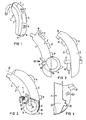
- Fig. 1 eine perspektivische Außenansicht eines hinter dem Ohr zu tragenden Hörgerätes, das die Erfindung beinhaltet,
- Fig. 2 eine Seitenansicht des erfindungsgemäß ausgebildeten Hörgerätes mit zwei Gehäuseschalen und einer Batterielade, teils im Längsschnitt,
- Fig. 3 eine Seitenansicht des Hörgerätes der Fig. 2 in Explosionsdarstellung, aus der der Aufbauvorgang des Gehäuses ersichtlich ist.
- Fig. 4 eine perspektivische Ansicht des Scharniers und der Rastmittel an der Innenwand der Innenschale.
- 1 is an external perspective view of a hearing aid to be worn behind the ear, which incorporates the invention,
- 2 is a side view of the hearing aid designed according to the invention with two housing shells and a battery charger, partly in longitudinal section,
- Fig. 3 is a side view of the hearing aid of Fig. 2 in an exploded view, from which the assembly process of the housing can be seen.
- Fig. 4 is a perspective view of the hinge and the locking means on the inner wall of the inner shell.
Die Fig. 1 zeigt ein hinter dem Ohr zu tragendes Hörgerät 1. Das Hörgerätgehäuse besteht aus einer Innenschale 2 und einer Außenschale 3. Bedienungselemente, insbesondere Lautstärkeregler 4 und Schalter 5 zum Umschalten zwischen Mikrofon und Telefonspule, ragen aus der Außenschale 3 auf der Rückfläche 3′ des Hörgerätes 1 hervor. Außerdem befindet sich auf der Rückfläche 3′ eine schwenkbare Klappe 6, die eine Stellergruppe verdeckt. Ein Traghaken 7 erleichtert die Positionierung des Hörgerätes 1 hinter dem Ohr des Hörgeschädigten und leitet gleichzeitig akustische Signale zum Ohr. Am gegenüberliegenden Ende befindet sich eine Batterielade 8 für eine Batterie 8′. Das Schwenken der Batterielade 8 wird durch einen Fingergriff 9 erleichtert, der an der Stirnfläche des Hörgerätgehäuses etwas hervorragt.1 shows a hearing aid 1 to be worn behind the ear. The hearing aid housing consists of an
Fig. 2 zeigt eine Seitenansicht des Hörgerätes 1, wobei das Ende mit der Batterielade 8 im Längsschnitt dargestellt ist. Die Batterielade 8 hängt an einem Scharnier 10, das durch zwei Zapfen 10.1, 10.2 gebildet ist. Das Scharnier 10 ist parallel zu einer Trennebene 25 angeordnet. Jeder Zapfen 10.1, 10.2 ist fest mit der Innenschale 2 an Seitenflächen 2′ und 2˝ verbunden. Ein Wulst 11 an der Batterielade 8 drückt an eine Schalenkante 12 an der Innenschale 2. Die Schalenkante 12 ist in bezug auf den Wulst 11 so angeordnet, daß der Wulst 11 in allen Schwenkstellungen der Batterielade 8 gegen die Kante 12 stößt. Die Batterielade 8 sitzt dadurch fest am Scharnier.Fig. 2 shows a side view of the hearing aid 1, the end with the
Wenn die Batterielade 8 eingeschwenkt ist, wie in der Fig. 2 dargestellt, kontaktieren die Kontaktfedern 13, 14 die Pole der Batterie 8'. Das Gerät 1 kann in dieser Stellung der Batterielade 8 mittels Schalter 5 eingeschaltet werden. Die Batterielade 8 kann nicht über diese Schwenkstellung weiter ins Gerät 1 hineingeschoben werden, da der Fingergriff 9 gegen eine Kante 15 der Außenschale 3 stößt. Zum Batteriewechsel wird die Lade 8 in entgegengesetzter Richtung aus dem Gerät 1 herausgeschwenkt.When the
Fig. 3 zeigt das Gerät 1 vor dem Zusammenbau. Zuerst wird die Batterielade 8 mittels Längsmulde 16 an den Zapfen 10.1, 10.2 aufgehängt. Die Lade 8 muß beim Aufhängen ganz nach oben geschwenkt sein, da sonst der Wulst 11 an der Kante 12 hakt. Sobald die Zapfen 10.1 und 10.2 tief in der Längsmulde 16 sitzen, kann die Lade 8 heruntergeschwenkt werden. Die Außenschale 3 wird auf die Innenschale so gesetzt, daß Läppchen 17 ineinandergreifen und die Noppe 18 an der Seitenfläche 2′ der Innenschale 2 - und eine entsprechende Noppe an der Seitenfläche 2˝ - in entsprechend ausgebildete Vertiefungen 19 (nicht sichtbar) an der Außenschale 3 einschnappt. Die Schalen 2, 3 werden mit Schrauben 20, die in einen Steg 21 an der Außenschale 3 fassen, fest miteinander verbunden. Um die Batterielade 8 von dem Gehäuse 2, 3 wieder zu entfernen, müßte die Außenschale 3 erst von der Innenschale 2 getrennt werden.Fig. 3 shows the device 1 before assembly. First, the
Fig. 4 zeigt einen Teil der Seitenfläche 2′ von der Innenseite. Der Zapfen 10.1 ragt aus der Fläche hervor. Oberhalb des Zapfens 10.1 ist die Schalenkante 12 zu erkennen. An der Fläche befindet sich außerdem ein ausgehöhlter Bereich 22, der etwa 1 mm tiefer liegt als die restliche Fläche der Innenseite. Zu diesem Bereich gehört insbesondere eine Aushöhlung 23. Die Aushöhlung 23 ergibt zusammen mit einem Vorsprung 24 an der Batterielade (siehe Fig. 3) die Rastmittel des Hörgerätes. Wenn die Batterielade 8 genügend weit in das Gehäuse 2, 3 eingeschwenkt ist, schnappt der Vorsprung 24 in die Aushöhlung 23 ein. Somit ist die Batterielade 8 fest geschlossen und bewegt sich lediglich, wenn Kraft auf den Fingergriff 9 ausgeübt wird.Fig. 4 shows a part of the side surface 2 'from the inside. The pin 10.1 protrudes from the surface. The
Claims (5)
- Hearing aid (1) having a housing to be worn behind the ear, consisting of at least two housing shells (2, 3), having a hinge (10) formed from at least one lug of a housing shell, and associated catch means (11, 12) and having a battery compartment (8) pivotal about the hinge and being capable of occupying a plurality of swivelled positions with the aid of the catch means, characterized in that the hinge (10) and the catch means (11, 12) are arranged on the same housing shell (2), with the hinge (10) extending parallel to a dividing plane of the housing shells (2, 3), in that the battery compartment (8) has a longitudinal depression (16), in that the battery compartment is mounted on the housing shell (2) and in that the battery compartment is hung on the hinge with its longitudinal depression.
- Hearing aid according to claim 1, characterized in that the catch means comprise at least one projection (24) and a groove (23).
- Hearing aid according to claim 2, characterized in that the projection (24) is arranged on the battery compartment (8) and the groove (23) is arranged on the inner side of the housing shell (2).
- Hearing aid according to claim 1, characterized in that a bulge (11) on the battery compartment (8) is fastened between the hinge (10) and an edge (12) of the housing shell (2) facing the battery compartment, in such a way that the battery compartment (8) is secured on the hinge when the aid (1) is assembled.
- Hearing aid according to claim 1, characterized in that the housing shell (2) comprises two side surfaces (2', 2''), at which a lug (10.1, 10.2) is located in each case.
Priority Applications (1)
| Application Number | Priority Date | Filing Date | Title |
|---|---|---|---|
| AT88115226T ATE77193T1 (en) | 1987-09-29 | 1988-09-16 | HEARING AID WITH BATTERY CHARGER. |
Applications Claiming Priority (2)
| Application Number | Priority Date | Filing Date | Title |
|---|---|---|---|
| DE8713088U | 1987-09-29 | ||
| DE8713088U DE8713088U1 (en) | 1987-09-29 | 1987-09-29 |
Publications (2)
| Publication Number | Publication Date |
|---|---|
| EP0309834A1 EP0309834A1 (en) | 1989-04-05 |
| EP0309834B1 true EP0309834B1 (en) | 1992-06-10 |
Family
ID=6812561
Family Applications (1)
| Application Number | Title | Priority Date | Filing Date |
|---|---|---|---|
| EP88115226A Expired - Lifetime EP0309834B1 (en) | 1987-09-29 | 1988-09-16 | Hearing aid with battery holder |
Country Status (4)
| Country | Link |
|---|---|
| US (1) | US5062138A (en) |
| EP (1) | EP0309834B1 (en) |
| AT (1) | ATE77193T1 (en) |
| DE (2) | DE8713088U1 (en) |
Families Citing this family (25)
| Publication number | Priority date | Publication date | Assignee | Title |
|---|---|---|---|---|
| EP0416155A1 (en) * | 1989-09-07 | 1991-03-13 | Siemens Aktiengesellschaft | Behind-the-ear hearing aid |
| US5133016A (en) * | 1991-03-15 | 1992-07-21 | Wallace Clark | Hearing aid with replaceable drying agent |
| EP0674465A1 (en) * | 1994-03-24 | 1995-09-27 | Phonak Ag | Battery-operated hearing aid |
| US5687242A (en) * | 1995-08-11 | 1997-11-11 | Resistance Technology, Inc. | Hearing aid controls operable with battery door |
| US6205227B1 (en) | 1998-01-31 | 2001-03-20 | Sarnoff Corporation | Peritympanic hearing instrument |
| US6101259A (en) * | 1998-08-03 | 2000-08-08 | Motorola, Inc. | Behind the ear communication device |
| EP1120010B1 (en) * | 1998-10-07 | 2010-04-21 | Oticon A/S | A hearing aid |
| ATE256375T1 (en) * | 1998-10-07 | 2003-12-15 | Oticon As | BEHIND-THE-EAR HEARING AID |
| US7403629B1 (en) | 1999-05-05 | 2008-07-22 | Sarnoff Corporation | Disposable modular hearing aid |
| US20070071265A1 (en) * | 1999-05-05 | 2007-03-29 | Leedom Marvin A | Disposable modular hearing aid |
| US7113611B2 (en) * | 1999-05-05 | 2006-09-26 | Sarnoff Corporation | Disposable modular hearing aid |
| DE10131747C2 (en) * | 2001-07-03 | 2003-12-24 | E A Olaf Greiner | Behind the ear hearing aid |
| US6741716B2 (en) | 2002-02-19 | 2004-05-25 | Starkey Laboratories, Inc. | Affixed behind-the-ear child resistant volume control cover |
| EP1304904B1 (en) * | 2002-05-07 | 2006-06-14 | Phonak Ag | Device for switching-on and switching-off of an electrical apparatus or element |
| DK1600038T3 (en) * | 2003-02-14 | 2010-06-07 | Widex As | Battery chamber for a hearing aid |
| US20040196996A1 (en) * | 2003-04-02 | 2004-10-07 | Feitel Mark A. | Hearing aid and hearing aid accessory cosmetic and functional cover |
| US20050179274A1 (en) * | 2004-02-13 | 2005-08-18 | Lera Leland M. | Hearing aid battery insertion tool |
| EP1439735B1 (en) * | 2004-03-10 | 2006-08-23 | Phonak Ag | Housing for hearing aids |
| US20060171550A1 (en) * | 2006-03-17 | 2006-08-03 | Audina Hearing Instruments, Inc. | BTE hearing aid component and hearing aid comprising same |
| DE102007021034B4 (en) * | 2007-05-04 | 2010-12-23 | Siemens Medical Instruments Pte. Ltd. | Hearing aid, in particular for carrying behind the ear |
| DE102007059723A1 (en) | 2007-12-12 | 2009-06-18 | Siemens Medical Instruments Pte. Ltd. | Hearing device with battery flap module |
| DE102008008668A1 (en) * | 2008-02-12 | 2009-08-13 | Siemens Medical Instruments Pte. Ltd. | Hearing device with battery compartment catch |
| US20120014547A1 (en) * | 2009-11-03 | 2012-01-19 | Sjursen Walter P | Hearing Instrument |
| WO2014113044A1 (en) * | 2013-01-15 | 2014-07-24 | Advanced Bionics Ag | Removable battery holder in a hearing assistance device |
| EP3145219B1 (en) * | 2015-09-21 | 2021-06-16 | Oticon A/s | Hearing device |
Family Cites Families (15)
| Publication number | Priority date | Publication date | Assignee | Title |
|---|---|---|---|---|
| US3031537A (en) * | 1960-06-02 | 1962-04-24 | Maico Electronics Inc | Acoustical device |
| DE1114848B (en) * | 1960-08-27 | 1961-10-12 | Micro Technic Hueber & Co | Housing for hearing aids for hearing impaired people to be worn behind the ear |
| DE1161599B (en) * | 1960-10-20 | 1964-01-23 | Wendton Werner Wendt K G | Switching device for small electrical devices operated with a replaceable energy source (battery) |
| US3475566A (en) * | 1966-01-04 | 1969-10-28 | Sonotone Corp | Battery holder and switch for hearing aid unit |
| GB1153195A (en) * | 1966-05-17 | 1969-05-29 | Amplivox Ltd | Improvements in or relating to Battery-Operated Electrical Apparatus |
| US3641288A (en) * | 1970-06-01 | 1972-02-08 | Electone Inc | Hearing aid switch |
| US3701862A (en) * | 1971-04-16 | 1972-10-31 | Gould Inc | Battery holder and three-position switch for hearing aid unit |
| DE2219970C3 (en) * | 1972-04-24 | 1982-11-25 | Siemens AG, 1000 Berlin und 8000 München | Electric hearing aid |
| DE2503253C3 (en) * | 1975-01-28 | 1986-05-07 | Robert Bosch Gmbh, 7000 Stuttgart | Small-sized device for the hearing impaired to be worn on the head |
| JPS6031438B2 (en) * | 1979-10-13 | 1985-07-22 | ソニー株式会社 | hearing aid battery case |
| DE8428516U1 (en) * | 1984-09-27 | 1986-01-23 | Siemens AG, 1000 Berlin und 8000 München | Hearing aid to be worn behind the ear |
| US4598177A (en) * | 1985-01-16 | 1986-07-01 | Sears, Roebuck, & Co. | Hearing aid with self-contained battery compartment and volume control |
| CH671490A5 (en) * | 1986-06-18 | 1989-08-31 | Phonak Ag | |
| DE3624568A1 (en) * | 1986-07-21 | 1988-01-28 | Siemens Ag | Hearing aid with a battery compartment which can be pivoted out |
| DE8621021U1 (en) * | 1986-08-05 | 1988-01-21 | Siemens Ag, 1000 Berlin Und 8000 Muenchen, De |
-
1987
- 1987-09-29 DE DE8713088U patent/DE8713088U1/de not_active Expired
-
1988
- 1988-09-16 DE DE8888115226T patent/DE3871887D1/en not_active Expired - Fee Related
- 1988-09-16 AT AT88115226T patent/ATE77193T1/en not_active IP Right Cessation
- 1988-09-16 EP EP88115226A patent/EP0309834B1/en not_active Expired - Lifetime
-
1990
- 1990-03-14 US US07/494,940 patent/US5062138A/en not_active Expired - Fee Related
Also Published As
| Publication number | Publication date |
|---|---|
| DE8713088U1 (en) | 1989-01-26 |
| EP0309834A1 (en) | 1989-04-05 |
| US5062138A (en) | 1991-10-29 |
| DE3871887D1 (en) | 1992-07-16 |
| ATE77193T1 (en) | 1992-06-15 |
Similar Documents
| Publication | Publication Date | Title |
|---|---|---|
| EP0309834B1 (en) | Hearing aid with battery holder | |
| EP0247390B1 (en) | In-the-ear hearing aid | |
| EP2091270B1 (en) | Hearing aid with latching battery compartment | |
| DE202013103611U1 (en) | Holding frame for connectors | |
| DE8328734U1 (en) | Hearing aid | |
| EP0198359B1 (en) | Loudspeaker unit | |
| AT524301B1 (en) | Magnetic bluetooth glasses | |
| DE102006055838A1 (en) | Flush-mounted multifunctional electromechanism | |
| EP0254925A1 (en) | Hearing aid with contactspring disposition | |
| AT390346B (en) | HEARING DEVICE WITH A LADDER FILM | |
| DE2849829A1 (en) | HANDLE CONNECTION OF INSULATED HOUSING FOR ELECTRICAL EQUIPMENT | |
| EP2144456A1 (en) | Hearing aid with lockable battery chamber | |
| EP0244671B1 (en) | Method and arrangement for carrying out an acoustic comparison measurement | |
| DE4121311C1 (en) | ||
| AT16303U1 (en) | monitor | |
| CH673743A5 (en) | Hearing aid with direct audio input - provided by audio connection cooperating with pivoted battery compartment | |
| EP0478892B1 (en) | In-the-ear hearing aid | |
| DE4411719C2 (en) | Surface-mounted socket | |
| DE3624568A1 (en) | Hearing aid with a battery compartment which can be pivoted out | |
| EP1449988B1 (en) | Catch module for window- and door-fittings | |
| EP3876365B1 (en) | Light adapter and rail lighting system | |
| DE102021123933B4 (en) | Full frame glasses structure | |
| DE2009837B1 (en) | Hearing aid to be worn behind the ear | |
| EP1480493B1 (en) | Housing construction for hearing devices and hearing aids | |
| DE7219476U (en) | Housing for electrical communications equipment |
Legal Events
| Date | Code | Title | Description |
|---|---|---|---|
| PUAI | Public reference made under article 153(3) epc to a published international application that has entered the european phase |
Free format text: ORIGINAL CODE: 0009012 |
|
| AK | Designated contracting states |
Kind code of ref document: A1 Designated state(s): AT CH DE FR GB IT LI NL |
|
| 17P | Request for examination filed |
Effective date: 19890425 |
|
| 17Q | First examination report despatched |
Effective date: 19911017 |
|
| GRAA | (expected) grant |
Free format text: ORIGINAL CODE: 0009210 |
|
| AK | Designated contracting states |
Kind code of ref document: B1 Designated state(s): AT CH DE FR GB IT LI NL |
|
| PG25 | Lapsed in a contracting state [announced via postgrant information from national office to epo] |
Ref country code: IT Free format text: LAPSE BECAUSE OF FAILURE TO SUBMIT A TRANSLATION OF THE DESCRIPTION OR TO PAY THE FEE WITHIN THE PRESCRIBED TIME-LIMIT;WARNING: LAPSES OF ITALIAN PATENTS WITH EFFECTIVE DATE BEFORE 2007 MAY HAVE OCCURRED AT ANY TIME BEFORE 2007. THE CORRECT EFFECTIVE DATE MAY BE DIFFERENT FROM THE ONE RECORDED. Effective date: 19920610 Ref country code: NL Effective date: 19920610 |
|
| REF | Corresponds to: |
Ref document number: 77193 Country of ref document: AT Date of ref document: 19920615 Kind code of ref document: T |
|
| REF | Corresponds to: |
Ref document number: 3871887 Country of ref document: DE Date of ref document: 19920716 |
|
| ET | Fr: translation filed | ||
| GBT | Gb: translation of ep patent filed (gb section 77(6)(a)/1977) | ||
| NLV1 | Nl: lapsed or annulled due to failure to fulfill the requirements of art. 29p and 29m of the patents act | ||
| PGFP | Annual fee paid to national office [announced via postgrant information from national office to epo] |
Ref country code: DE Payment date: 19921124 Year of fee payment: 5 |
|
| PGFP | Annual fee paid to national office [announced via postgrant information from national office to epo] |
Ref country code: CH Payment date: 19921215 Year of fee payment: 5 |
|
| RAP2 | Party data changed (patent owner data changed or rights of a patent transferred) |
Owner name: SIEMENS AUDIOLOGISCHE TECHNIK GMBH |
|
| PLBE | No opposition filed within time limit |
Free format text: ORIGINAL CODE: 0009261 |
|
| STAA | Information on the status of an ep patent application or granted ep patent |
Free format text: STATUS: NO OPPOSITION FILED WITHIN TIME LIMIT |
|
| 26N | No opposition filed | ||
| PGFP | Annual fee paid to national office [announced via postgrant information from national office to epo] |
Ref country code: GB Payment date: 19930816 Year of fee payment: 6 |
|
| PGFP | Annual fee paid to national office [announced via postgrant information from national office to epo] |
Ref country code: AT Payment date: 19930827 Year of fee payment: 6 |
|
| PGFP | Annual fee paid to national office [announced via postgrant information from national office to epo] |
Ref country code: FR Payment date: 19930917 Year of fee payment: 6 |
|
| PG25 | Lapsed in a contracting state [announced via postgrant information from national office to epo] |
Ref country code: CH Effective date: 19930930 Ref country code: LI Effective date: 19930930 |
|
| REG | Reference to a national code |
Ref country code: CH Ref legal event code: PL |
|
| PG25 | Lapsed in a contracting state [announced via postgrant information from national office to epo] |
Ref country code: DE Effective date: 19940601 |
|
| PG25 | Lapsed in a contracting state [announced via postgrant information from national office to epo] |
Ref country code: GB Effective date: 19940916 Ref country code: AT Effective date: 19940916 |
|
| GBPC | Gb: european patent ceased through non-payment of renewal fee |
Effective date: 19940916 |
|
| PG25 | Lapsed in a contracting state [announced via postgrant information from national office to epo] |
Ref country code: FR Effective date: 19950531 |
|
| REG | Reference to a national code |
Ref country code: FR Ref legal event code: ST |