EP0309314A1 - Container for beverages convertible into a tumbler or other drinking utensil - Google Patents
Container for beverages convertible into a tumbler or other drinking utensil Download PDFInfo
- Publication number
- EP0309314A1 EP0309314A1 EP88402298A EP88402298A EP0309314A1 EP 0309314 A1 EP0309314 A1 EP 0309314A1 EP 88402298 A EP88402298 A EP 88402298A EP 88402298 A EP88402298 A EP 88402298A EP 0309314 A1 EP0309314 A1 EP 0309314A1
- Authority
- EP
- European Patent Office
- Prior art keywords
- glass
- container according
- cap
- drinking
- plug
- Prior art date
- Legal status (The legal status is an assumption and is not a legal conclusion. Google has not performed a legal analysis and makes no representation as to the accuracy of the status listed.)
- Withdrawn
Links
Images

Classifications
-
- A—HUMAN NECESSITIES
- A47—FURNITURE; DOMESTIC ARTICLES OR APPLIANCES; COFFEE MILLS; SPICE MILLS; SUCTION CLEANERS IN GENERAL
- A47G—HOUSEHOLD OR TABLE EQUIPMENT
- A47G19/00—Table service
- A47G19/22—Drinking vessels or saucers used for table service
- A47G19/2205—Drinking glasses or vessels
-
- B—PERFORMING OPERATIONS; TRANSPORTING
- B65—CONVEYING; PACKING; STORING; HANDLING THIN OR FILAMENTARY MATERIAL
- B65D—CONTAINERS FOR STORAGE OR TRANSPORT OF ARTICLES OR MATERIALS, e.g. BAGS, BARRELS, BOTTLES, BOXES, CANS, CARTONS, CRATES, DRUMS, JARS, TANKS, HOPPERS, FORWARDING CONTAINERS; ACCESSORIES, CLOSURES, OR FITTINGS THEREFOR; PACKAGING ELEMENTS; PACKAGES
- B65D23/00—Details of bottles or jars not otherwise provided for
Definitions
- the present invention relates to a container for storing a drink, in particular a wine, constituted by a body of a drinking glass or other drinking utensil, the mouth opening of which is hermetically closed by a removable capsule and which includes a filling passage formed through the bottom of the body and closed by a tight plug.
- a bottle of wine once uncorked, no longer ensures the conservation of its content and it appeared desirable to market the wine, and in particular the grands crus, in smaller individual doses, corresponding for example to the normal quantity absorbed on average by one person during a meal.
- a packaging for drinks constituted by a body, having the general shape of a drinking glass, provided with an annular base inside which is provided a neck provided, after filling the glass with an airtight capsule, the upper opening of the drinking glass being closed by a removable waterproof cover.
- beverage packaging has been found to be complicated to manufacture with regard to the base and unattractive and practical for the consumption of drinks deemed to be noble, such as wines of controlled designation or alcohols.
- One of the objects of the present invention is precisely to provide a beverage packaging which is more practical and more economical to manufacture and which ensures better conservation of the beverage it contains while taking the form of a real glass drink suitable for tasting noble drinks such as fine wines.
- the filling passage continues beyond the bottom of the body by a neck constituting a hollow stem for the glass in its position of use for drinking.
- the container according to the invention which forms a drinking glass also constitutes a small overturned bottle, the closed cavity of the body corresponding to the body of the bottle and the hollow foot at its neck.
- the filling by the foot of the body makes it possible to visualize as well as possible the minimum of air introduced into the container, in order to avoid oxygenation of the wine and thus to ensure a good aging of this one. this.
- the deposits of aged wine can advantageously be stored and masked in the glass base which will act as a decanting well during the tasting.
- the capsule is constituted by a cap which covers the upper edge or "drinking" of the glass and covers at least the upper side wall of the glass by a side skirt attached to anchoring members projecting from the side wall of the glass.
- these anchoring members preferably being constituted by two pellets fixed in recesses or cavities in the side wall of the glass and fitting into cutouts made in the side skirt of the cap.
- the pellets each have a passage through which a guarantee strip encircles the glass body and the cap, to prevent any fraudulent removal of the cap.
- the mouth opening of the body or drinking glass is defined by a wall section with a substantially straight cylindrical inner face, on which the flexible cap fits fits tightly by a groove formed between its skirt. lateral and a hollow central cover, to achieve a hermetic closure of the body.
- the face of the seal which comes into contact with said wall section comprises at least one annular seal which can be constituted by a compressible one-piece annular rib. with the cover and whose cross section substantially forms a half section of O-ring.
- the container according to the invention offers the same guarantees of conservation and inviolability of its content as traditional bottles, which is more particularly advantageous for fine wines.
- this container can be used to safely package small quantities of wine, such as conventional doses of 10, 18.7 or 25 centilitres, which allows in particular during the same meal to diversify the good wines in minimal quantities, for example in conformity with the legislation on the alcohol level of the drivers.
- the containers according to the invention are compact and can be stacked on top of each other, resulting in greatly simplified storage and transport.
- the inner cover is preferably given larger dimensions than those of the foot or the bottom of the body.
- the wine can be offered to consumers in a new original and attractive presentation, which can be embellished, in particular by making the anchoring tablets in the form of false stones or in another aesthetic aspect. .
- the opening of the container according to the invention can be done without the use of a corkscrew and without leaving traces in the wine or on the edge of the glass, unlike what is the case with corks. cork from traditional bottles.
- the side skirt of the cap with two tabs which are joined by a tear-off strip formed, in the cap, by two pre-cutting lines, the cut-outs of the cap which receive the anchoring pads preferably being made in these tabs.
- the container according to the invention automatically takes the form of a drinking glass, which means that it will find a particularly interesting application in collective restaurants, self-service restaurants, tea rooms and passenger transport, such as airplanes.
- the hollow stem stem is closed by a stopper secured to a base to form, if necessary, either a stemmed glass or a drinking glass of generally cylindrical shape.
- the stopper may have, on its connection with the base, a groove or a slot causing the separation of said base in the event of an attempt to fraudulently open the stopper.
- the stopper is hollow and has a small thickness relative to the base, so as to cause the separation of the stopper and the base in the event of an attempted fraudulent opening of the cap.
- at least the bottom of the hollow plug and the closure cap of the removable capsule are made oxygen tight, for example by a thin coating of aluminum.
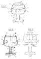
- Figure 1 shows a container according to the invention consisting of a body 1 of drinking glass of "balloon" shape capped with a removable hermetic capsule 2 preferably flexible.
- the bottom 3 of the glass is connected all around a central opening 4, to the tubular wall of a foot rod 5 which is hollowed out by a central filling passage 6 over its entire height, to lead, under its base 7, to a filling orifice 8.
- the stem 5 thus forms a neck for filling the glass.
- Under the base 7, a balancing sole 9 can also be glued which has a hole 10 extending the filling orifice 8.
- the upper side wall 11 of the glass which curls slightly inwards towards its free edge, ends in a short section with a straight cylindrical inner face 12a delimiting the mouth opening 12 (and the upper rim or "drinking" 12b) of the glass.
- Two shallow rectangular recesses or cavities 13, 14 are formed externally in the side wall 11 of the glass, in diametrically opposite positions. These cavities 13, 14 can be replaced by one-piece anchoring projections with the body 1.
- the capsule 2 generally made of flexible plastic material, constitutes a cap which has an annular groove or cavity 15 formed between a recessed or hollow central cover. 16, substantially the same diameter as the mouth opening 12, and a side skirt 17. Thanks to this groove 15, the cap 2 fits on the free upper or “drinking" edge 12b of the glass, the cover 16 coming into leaktight contact with the inner face 12a of the mouth opening 12, by means of annular seals constituted here by two compressible radial and circular ribs 18 integral with the seal 16.
- the seal between the cap 2 and the upper edge of the glass can also be produced by pressing the bottom of the groove 25, if necessary coated with a flexible sealing washer on the free upper annular edge 12b of the glass.
- This annular edge having a small width and a rounded section, it is thus possible to obtain relatively high sealing pressures.
- the cover 16 being in place in a leaktight manner, a space or capacity of glass 1a is determined inside the glass body 1 which can be filled through the central passage 6. In fact, if the body 1 from above, this body should be handled in conditions of instability which would not allow filling, leaving a small and substantially constant volume of air.
- the skirt 17 is applied externally over the entire side wall 11 of the fragile upper part carrying the "drink" of the glass and protects it from impact.
- the skirt 17 of the cap 2 is extended at the lower part 11a of the side wall of the glass towards the stem of the glass 5, by two diametrically opposite tongues 19, 20 and which each have a cutout 21 or 22 (see Figures 4 and 6).
- each cutout there is an insert or an anchoring projection 23 or 24, of complementary shape, which is itself fixed, preferably by gluing, in one of the respective recesses 13 or 14 of the lower side wall 11a of the glass 1 (see figure 2).
- the cap 2 is thus anchored to the glass 1.
- the anchoring projections can, as already mentioned, come directly from molding with the lower wall 11a of the glass body 1 to produce a substantially smooth glass body wall. inside the drinking glass.
- the anchoring pads 23, 24, which have a flattened U shape, may further comprise or form passages 23a, 24a for a paper guarantee strip 27 which is applied over the entire circumference of the side wall of the body of glass 1 by spanning the two tabs 19, 20 of the side skirt 17 of the cap 2.
- the two ends of this guarantee strip 27 are joined, on the front of the glass 1, by a self-adhesive pad 28 ( Figure 1).
- the anchoring pads 23 or 24 may be in any number greater than 1 and include aesthetic patterns such as seals, coats of arms or pearls.
- the container just described is filled, by turning the glass body 1 hermetically capped with its cap 2 and then introducing the liquid (wine or other drink) through the filling orifice 8.
- a tight stopper 29 only fills part of the passage 6.
- the remaining free part 6a of the passage 6 can thus serve as a decanting well for the deposits of the wine before its presentation, this well avoiding more cloudy wine during tasting.
- the two tabs 19, 20 can be connected together by a tear-off strip 31 formed in the cap 2 by two precut lines 32, 33, visible in FIG. 3.
- the main difference lies in the fact that the hollow base rod 5 is closed by a plug 35 secured to a base 7 or 36 to form a glass base.
- the entire plug 35 and its base can be made of materials such as soft or hard plastic and even glass.
- the plug 35 may include at its end a hooking lip 37 and one or more sealing ribs 38 fulfilling the same function as the ribs 18.
- the sealing of the plug 35 may be insured by separate sealing means, for example by O-rings which are carried by the plug 35 or by the passage 6 of the foot rod 5, but also by cooperation of the thin and elastic wall of the hollow plug 35, with at least one bead or annular projection formed inside the passage 6, preferably at the entrance of this passage from the outside of the body 1.
- connection between the base 7 and the plug 35 can be provided in place of '' a fillet or rounded connection, a groove or a breaking slot 39 making it possible to easily separate the base 7 from the plug 35 engaged in the passage 6 of the hollow foot rod 5, so as to transform the solid glass into a bottle whose the hollow foot rod 5 constitutes the neck.
- the rupture groove 39 can also be used to prevent fraudulent manipulations on drinking glasses filled with drink because any manipulation of the stopper 35 in order to obtain its opening can only be done via the base 7 or 37 which is then separates from the plug 35.
- the plug 35 can advantageously be hollow and have a small thickness which will inevitably lead to separation of the base and the plug in the event of attempts to extract the plug fraudulently.
- the assembled glass constitutes a stemmed glass used in particular for the tasting of white wines and alcohols.
- glue rods 41 and 42 of the anchoring pads 23 and 24 are glued into corresponding holes 43 and 44 made on the lower side wall 11a of the glass, for example by locking the guarantee strip 27 whose holes 27a and 27b are crossed by the rods 41 and 42.
- the cover 16 of the cap 2 is then applied to the opening 12 by engaging the pads 23 and 24 in the cutouts 21 and 22 of the tongues 19 and 20, this which retains the cap 2 in position by applying the ribs 18 to the side wall 12a.
- the plugging by the cap 35 accompanied by the base 7 forms a complete drinking glass on which a tax sticker 40 is affixed or caused to be affixed by the administration, preferably on the guarantee strip 27.
- the body 1 is intended to cooperate with a stopper 35 surrounded by a base 36 of cylindrical annular shape to produce a drinking glass of generally cylindrical shape.
- the body 1 shown without its cap 2 may have on its upper side wall 11 a flange 11b for hooking the cap and at the lower part of its side wall an annular recess 45 on which the upper edge 46 of the base can be fitted 36 when the plug 35 is tightly engaged in the relatively short stem 5 to form the equivalent of a cylindrical glass with a thick, robust and stable bottom because its base can be made of a plastic material imitating glass but more resilient.
- the parts of the container which are not made of glass or other material which is perfectly gas-tight and which are liable to be traversed in the direction of the internal capacity 12 by the oxygen in the air such as the cover 16 and the bottom of the cap 35 when the latter is hollow, can advantageously be made oxygen-tight, for example aluminized or otherwise coated with a thin layer of aluminum, inside and / or outside in order to avoid term any action of oxygen in the wine or stored drink.
- the container according to the invention can be used in all sizes for the packaging of all kinds of drinks including wine and that the glass or the transparent plastic material which constitutes its element. basic, can be replaced by any other suitable material or any other utensil for drinking, such as a cup, a cup, etc ...
- the cover 16 may have a premarked part to be pushed in or punctured for the passage of a suction straw.
Abstract
Description
La présente invention concerne un récipient pour la conservation d'une boisson, en particulier d'un vin, constitué par un corps de verre à boire ou autre ustensile pour boire dont l'ouverture de mise en bouche est hermétiquement fermée par une capsule amovible et qui comprend un passage de remplissage ménagé à travers le fond du corps et obturé par un bouchon étanche.The present invention relates to a container for storing a drink, in particular a wine, constituted by a body of a drinking glass or other drinking utensil, the mouth opening of which is hermetically closed by a removable capsule and which includes a filling passage formed through the bottom of the body and closed by a tight plug.
Une bouteille de vin, une fois débouchée, n'assure plus la conservation de son contenu et il est apparu souhaitable de commercialiser le vin, et notamment les grands crus, en plus petites doses individuelles, correspondant par exemple à la quantité normale absorbée en moyenne par une seule personne au cours d'un repas.A bottle of wine, once uncorked, no longer ensures the conservation of its content and it appeared desirable to market the wine, and in particular the grands crus, in smaller individual doses, corresponding for example to the normal quantity absorbed on average by one person during a meal.
Il a déjà été proposé, notamment dans FR-A-2286765 un emballage pour boisson constitué par un corps, ayant la forme générale d'un verre à boire, pourvu d'un pied annulaire à l'intérieur duquel est prévu un goulot muni, après remplissage du verre, d'une capsule hermétique, l'ouverture supérieure du verre à boire étant obturée par un couvercle étanche amovible.It has already been proposed, in particular in FR-A-2286765, a packaging for drinks constituted by a body, having the general shape of a drinking glass, provided with an annular base inside which is provided a neck provided, after filling the glass with an airtight capsule, the upper opening of the drinking glass being closed by a removable waterproof cover.
De tels emballages pour boisson se sont révélés compliqués à fabriquer en ce qui concerne le pied et peu esthétiques et pratiques pour la consommation de boissons réputées nobles telles que les vins d'appellation contrôlée ou les alcools. L'un des objets de la présente invention est précisément de proposer un emballage pour boisson qui soit plus pratique et plus économique à fabriquer et qui assure une conservation meilleure de la boisson qu'il contient tout en prenant la forme d'un véritable verre à boire adapté à la dégustation des boissons nobles telles que les vins fins.Such beverage packaging has been found to be complicated to manufacture with regard to the base and unattractive and practical for the consumption of drinks deemed to be noble, such as wines of controlled designation or alcohols. One of the objects of the present invention is precisely to provide a beverage packaging which is more practical and more economical to manufacture and which ensures better conservation of the beverage it contains while taking the form of a real glass drink suitable for tasting noble drinks such as fine wines.
A cet effet, selon l'invention, le passage de remplissage se poursuit au-delà du fond du corps par un goulot constituant une tige de pied creuse pour le verre dans sa position d'utilisation pour boire.To this end, according to the invention, the filling passage continues beyond the bottom of the body by a neck constituting a hollow stem for the glass in its position of use for drinking.
Le récipient selon l'invention qui forme un verre à boire constitue également une petite bouteille renversée, la cavité fermée du corps correspondant au corps de la bouteille et le pied creux à son goulot. Tout comme dans les bouteilles traditionnelles, le remplissage par le pied du corps permet de visualiser au mieux le minimum d'air introduit dans le récipient, en vue d'éviter l'oxygénation du vin et d'assurer ainsi un bon vieillissement de celui-ci. De plus les dépôts du vin vieilli pourront avantageusement être stockés et masqués dans le pied de verre qui jouera le rôle de puits de décantation au cours de la dégustation.The container according to the invention which forms a drinking glass also constitutes a small overturned bottle, the closed cavity of the body corresponding to the body of the bottle and the hollow foot at its neck. As in traditional bottles, the filling by the foot of the body makes it possible to visualize as well as possible the minimum of air introduced into the container, in order to avoid oxygenation of the wine and thus to ensure a good aging of this one. this. In addition, the deposits of aged wine can advantageously be stored and masked in the glass base which will act as a decanting well during the tasting.
Avantageusement, la capsule est constituée par un capuchon qui coiffe l'arête supérieure ou "buvant" du verre et recouvre au moins la paroi latérale supérieure du verre par une jupe latérale accrochée à des organes d'ancrage en saillie sur la paroi latérale du verre, ces organes d'ancrage étant de préférence constitués par deux pastilles fixées dans des renfoncements ou cavités de la paroi latérale du verre et s'encastrant dans des découpes ménagées dans la jupe latérale du capuchon.Advantageously, the capsule is constituted by a cap which covers the upper edge or "drinking" of the glass and covers at least the upper side wall of the glass by a side skirt attached to anchoring members projecting from the side wall of the glass. , these anchoring members preferably being constituted by two pellets fixed in recesses or cavities in the side wall of the glass and fitting into cutouts made in the side skirt of the cap.
Selon une autre caractéristique de l'invention, les pastilles comportent chacune un passage traversé par une bande de garantie encerclant le corps de verre et le capuchon, pour prévenir tout enlèvement frauduleux du capuchon.According to another characteristic of the invention, the pellets each have a passage through which a guarantee strip encircles the glass body and the cap, to prevent any fraudulent removal of the cap.
Avantageusement, l'ouverture de mise en bouche du corps ou verre à boire est définie par une section de paroi à face intérieure sensiblement cylindrique droite, sur laquelle le capuchon souple s'emboîte s'emboîte de façon étanche par une gorge formée entre sa jupe latérale et un opercule central en creux, pour réaliser ainsi une fermeture hermétique du corps. Pour garantir une obturation de longue durée, la face de l'opercule qui vient en contact avec ladite section de paroi comporte au moins un joint annulaire d'étanchéité qui peut être constitué par une nervure annulaire compressible monobloc avec l'opercule et dont la section transversale forme sensiblement une demi-section de joint torique.Advantageously, the mouth opening of the body or drinking glass is defined by a wall section with a substantially straight cylindrical inner face, on which the flexible cap fits fits tightly by a groove formed between its skirt. lateral and a hollow central cover, to achieve a hermetic closure of the body. To guarantee a long-term sealing, the face of the seal which comes into contact with said wall section comprises at least one annular seal which can be constituted by a compressible one-piece annular rib. with the cover and whose cross section substantially forms a half section of O-ring.
Doté de toutes ces caractéristiques, le récipient conforme à l'invention offre les mêmes garanties de conservation et d'inviolabilité de son contenu que les bouteilles traditionnelles, ce qui est plus particulièrement avantageux pour les vins fins.Equipped with all these characteristics, the container according to the invention offers the same guarantees of conservation and inviolability of its content as traditional bottles, which is more particularly advantageous for fine wines.
Il s'ensuit que ce récipient peut être utilisé pour conditionner en toute sécurité de petites quantités de vin, telles que les doses classiques de 10, 18,7 ou 25 centilitres, ce qui permet notamment au cours d'un même repas de diversifier les bons crus en quantités minimales, conformes par exemple à la législation sur l'alcoolémie des conducteurs.It follows that this container can be used to safely package small quantities of wine, such as conventional doses of 10, 18.7 or 25 centilitres, which allows in particular during the same meal to diversify the good wines in minimal quantities, for example in conformity with the legislation on the alcohol level of the drivers.
Un autre avantage des récipients selon l'invention est qu'ils sont d'un encombrement réduit et peuvent être empilés les uns sur les autres d'où il résulte un stockage et un transport grandement simplifiés. Pour favoriser cet empilage, on donnera de préférence à l'opercule des dimensions intérieures supérieures à celles du pied ou du fond du corps.Another advantage of the containers according to the invention is that they are compact and can be stacked on top of each other, resulting in greatly simplified storage and transport. To favor this stacking, the inner cover is preferably given larger dimensions than those of the foot or the bottom of the body.
Par ailleurs, grâce à la présente invention, le vin peut être proposé aux consommateurs sous une nouvelle présentation originale et attrayante, qui peut être enjolivée, notamment par la réalisation des pastilles d'ancrage sous la forme de fausses pierres ou sous un autre aspect esthétique.Furthermore, thanks to the present invention, the wine can be offered to consumers in a new original and attractive presentation, which can be embellished, in particular by making the anchoring tablets in the form of false stones or in another aesthetic aspect. .
On ajoutera que l'ouverture du récipient selon l'invention peut se faire sans l'utilisation d'un tire-bouchon et sans laisser de traces dans le vin ou sur le bord du verre, contrairement à ce qui est le cas avec les bouchons de liège des bouteilles traditionnelles.We will add that the opening of the container according to the invention can be done without the use of a corkscrew and without leaving traces in the wine or on the edge of the glass, unlike what is the case with corks. cork from traditional bottles.
A ce sujet, pour faciliter l'ouverture du récipient, on peut avantageusement doter la jupe latérale du capuchon de deux languettes qui sont réunies par une bande arrachable formée, dans le capuchon, par deux lignes de pré-découpage, les découpes du capuchon qui reçoivent les pastilles d'ancrage étant de préférence réalisées dans ces languettes.In this regard, to facilitate the opening of the container, it is advantageous to provide the side skirt of the cap with two tabs which are joined by a tear-off strip formed, in the cap, by two pre-cutting lines, the cut-outs of the cap which receive the anchoring pads preferably being made in these tabs.
Une fois le capuchon enlevé, par un simple effort d'arrachement exercé sur les deux languettes, le récipient selon l'invention prend automatiquement la forme d'un verre à boire, ce qui fait qu'il trouvera une application particulièrement intéressante dans les restaurants collectifs, les restaurants self-services, les salons de thé et les moyens de transports de voyageurs, comme les avions.Once the cap has been removed, by a simple tearing force exerted on the two tabs, the container according to the invention automatically takes the form of a drinking glass, which means that it will find a particularly interesting application in collective restaurants, self-service restaurants, tea rooms and passenger transport, such as airplanes.
Selon un autre mode encore de réalisation de l'invention, la tige de pied creuse est obturée par un bouchon solidaire d'un socle pour former, le cas échéant, soit un verre à pied, soit un verre à boire de forme générale cylindrique. Le bouchon peut comporter sur sa liaison avec le socle une gorge ou une fente provoquant la séparation dudit socle en cas de tentative d'ouverture frauduleuse du bouchon.According to yet another embodiment of the invention, the hollow stem stem is closed by a stopper secured to a base to form, if necessary, either a stemmed glass or a drinking glass of generally cylindrical shape. The stopper may have, on its connection with the base, a groove or a slot causing the separation of said base in the event of an attempt to fraudulently open the stopper.
Selon un mode de réalisation de l'invention améliorant encore la sécurité de la conservation de la boisson dans le corps de verre, le bouchon est creux et présente une faible épaisseur par rapport au socle, de manière à provoquer la séparation du bouchon et du socle en cas de tentative d'ouverture frauduleuse du bouchon. De plus, au moins le fond du bouchon creux et l'opercule de fermeture de la capsule amovible sont rendus étanches à l'oxygène, par exemple par un mince revêtement d'aluminium.According to an embodiment of the invention further improving the security of the conservation of the drink in the glass body, the stopper is hollow and has a small thickness relative to the base, so as to cause the separation of the stopper and the base in the event of an attempted fraudulent opening of the cap. In addition, at least the bottom of the hollow plug and the closure cap of the removable capsule are made oxygen tight, for example by a thin coating of aluminum.
D'autres buts, caractéristiques et avantages apparaîtront à la lecture de la description de divers modes de réalisation, faite à titre non limitatif et en regard du dessin annexé où:
- - la figure 1 est une vue en perspective d'un premier mode de réalisation du récipient selon l'invention;
- - la figure 2 est une vue en coupe verticale selon la ligne II-II de la figure 3;
- - la figure 3 est une vue latérale du récipient des figures 1 et 2;
- - la figure 4 est un agrandissement d'un détail de la figure 2;
- - la figure 5 représente en demi-coupe verticale le verre nu constituant le corps du récipient des figures 1 à 3;
- - la figure 6 est une vue éclatée en perspective d'un deuxième mode de réalisation du récipient selon l'invention, en forme de verre à pied;
- - la figure 7 est une vue éclatée en perspective d'un troisième mode de réalisation du récipient selon l'invention.
- - Figure 1 is a perspective view of a first embodiment of the container according to the invention;
- - Figure 2 is a vertical sectional view along line II-II of Figure 3;
- - Figure 3 is a side view of the container of Figures 1 and 2;
- - Figure 4 is an enlargement of a detail of Figure 2;
- - Figure 5 shows in vertical half-section the bare glass constituting the body of the container of Figures 1 to 3;
- - Figure 6 is an exploded perspective view of a second embodiment of the container according to the invention, in the form of stemware;
- - Figure 7 is an exploded perspective view of a third embodiment of the container according to the invention.
La figure 1 montre un récipient selon l'invention consistant en un corps 1 de verre à boire de forme "ballon" coiffé d'une capsule hermétique amovible 2 de préférence souple.Figure 1 shows a container according to the invention consisting of a
Comme le montre la figure 5, le fond 3 du verre se raccorde tout autour d'une ouverture centrale 4, à la paroi tubulaire d'une tige de pied 5 qui est évidée par un passage central de remplissage 6 sur toute sa hauteur, pour déboucher, sous son socle 7, sur un orifice de remplissage 8. La tige de pied 5 forme ainsi un goulot de remplissage du verre. Sous le socle 7, peut en outre être collée une semelle d'équilibrage 9 qui présente un trou 10 prolongeant l'orifice de remplissage 8.As shown in FIG. 5, the bottom 3 of the glass is connected all around a central opening 4, to the tubular wall of a
Par ailleurs, la paroi latérale supérieure 11 du verre, qui se recourbe légèrement vers l'intérieur en direction de son bord libre, se termine par une courte section à face intérieure cylindrique droite 12a délimitant l'ouverture de mise en bouche 12 (et le rebord supérieur ou "buvant" 12b) du verre. Deux renfoncements ou cavités rectangulaires peu profonds 13, 14 sont formés extérieurement dans la paroi latérale 11 du verre, dans des positions diamétralement opposées. Ces cavités 13, 14 peuvent être remplacées par des saillies d'ancrage monobloc avec le corps 1.Furthermore, the
Comme on peut le voir clairement, sur la figure 2 et mieux encore sur la figure 4, la capsule 2, généralement réalisée en matière plastique flexible, constitue un capuchon qui présente une gorge ou cavité annulaire 15 formée entre un opercule central renfoncé ou en creux 16, sensiblement de même diamètre que l'ouverture de mise en bouche 12, et une jupe latérale 17. Grâce à cette gorge 15, le capuchon 2 s'emboîte sur le bord supérieur libre ou "buvant" 12b du verre, l'opercule 16 venant en contact étanche avec la face intérieure 12a de l'ouverture de mise en bouche 12, par l'intermédiaire de joints d'étanchéité annulaire constitués ici de deux nervures compressibles radiales et circulaires 18 monobloc avec l'opercule 16. L'étanchéité entre le capuchon 2 et le bord supérieur du verre peut également être réalisé par appui du fond de la gorge 25, revêtu le cas échéant d'une rondelle souple d'étanchéité sur le bord annulaire supérieur libre 12b du verre. Ce bord annulaire présentant une faible largeur et une section arrondie, on peut ainsi obtenir des pressions d'étanchéité relativement importantes. L'opercule 16 étant en place de façon étanche, on détermine à l'intérieur du corps de verre 1 un espace ou capacité de verre 1ª que l'on peut remplir par le passage central 6. En effet, si l'on remplissait le corps 1 par le haut, il faudrait manipuler ce corps dans des conditions d'instabilité qui ne permettraient pas de remplir en laissant un volume d'air faible et sensiblement constant. La jupe 17 s'applique extérieurement sur toute la paroi latérale 11 de la partie supérieure fragile portant le "buvant" du verre et la protège des chocs.As can be clearly seen in FIG. 2 and better still in FIG. 4, the capsule 2, generally made of flexible plastic material, constitutes a cap which has an annular groove or
En se reportant maintenant à la figure 2, on peut voir que la jupe 17 du capuchon 2 se prolonge à la partie inférieure 11a de la paroi latérale du verre vers la tige de pied 5 du verre, par deux languettes 19, 20, diamétralement opposées et qui comportent chacune une découpe 21 ou 22 (voir les figures 4 et 6). Dans chaque découpe s'encastre une pastille ou saillie d'ancrage 23 ou 24, de forme complémentaire, qui est elle-même fixée, de préférence par collage, dans l'un des renfoncements respectifs 13 ou 14 de la paroi latérale inférieure 11a du verre 1 (voir figure 2). Le capuchon 2 est ainsi ancré au verre 1. Les saillies d'ancrage peuvent, venir, comme on l'a déjà mentionné, directement de moulage avec la paroi inférieure 11a du corps de verre 1 pour réaliser une paroi de corps de verre sensiblement lisse à l'intérieur du verre à boire.Referring now to FIG. 2, it can be seen that the
Les pastilles d'ancrage 23, 24, qui ont une forme en U aplati, peuvent comporter ou former en outre des passages 23a, 24a pour une bande de garantie en papier 27 qui s'applique sur toute la circonférence de la paroi latérale du corps de verre 1 en enjambant les deux languettes 19, 20 de la jupe latérale 17 du capuchon 2. Les deux extrémités de cette bande de garantie 27 sont réunies, sur le devant du verre 1, par une pastille auto-collante 28 (figure 1). Les pastilles d'ancrage 23 ou 24 peuvent être en nombre quelconque supérieur à 1 et comporter des motifs esthétiques tels que des sceaux, des blasons ou des perles.The
On procède d'habitude au remplissage du récipient qui vient d'être décrit, en retournant le corps de verre 1 hermétiquement coiffé de son capuchon 2 puis en introduisant le liquide (vin ou autre boisson) par l'orifice de remplissage 8. Le corps 1 encapuchonné et son pied évidé 5 étant remplis, on obture l'orifice 8 à l'aide d'un bouchon étanche 29, par exemple un bouchon de liège, sur lequel on peut former une capsule de surbouchage en cire 30 qui vient occuper le trou 10 de la semelle 9. On remarquera sur la figure 2 que le bouchon 29 remplit seulement une partie du passage 6. La partie restant libre 6a du passage 6 peut ainsi servir de puits de décantation pour les dépôts du vin avant sa présentation, ce puits évitant de plus le trouble du vin au cours de sa dégustation.Usually, the container just described is filled, by turning the
Pour ouvrir le récipient, il suffit de tirer fortement sur les deux languettes 19 et 20 pour tout d'abord déchirer la bande de garantie 27 puis déloger chaque languette de sa pastille d'ancrage 23 ou 24. Le capuchon 2 peut ensuite s'extraire axialement vers le haut du "buvant" 12b du verre 1 reposant droit sur son socle 7 ou sa semelle 9. Pour faciliter l'ouverture du verre, les deux languettes 19, 20 peuvent être reliées entre elles par une bande arrachable 31 formée dans le capuchon 2 par deux lignes de prédécoupage 32, 33, visibles sur la figure 3.To open the container, simply pull strongly on the two
Pour les deux modes de réalisation représentés sur les figures 6 et 7, la différence principale réside dans le fait que la tige de pied creuse 5 est obturée par un bouchon 35 solidaire d'un socle 7 ou 36 pour former un pied de verre.For the two embodiments shown in FIGS. 6 and 7, the main difference lies in the fact that the
L'ensemble du bouchon 35 et de son socle peut être réalisé en des matériaux tels que la matière plastique molle ou dure et même en verre. Dans le cas d'une réalisation en matière plastique, le bouchon 35 peut comporter à son extrémité une lèvre d'accrochage 37 et une ou plusieurs nervures d'étanchéité 38 remplissant la même fonction que les nervures 18. L'étanchéité du bouchon 35 peut être assurée par des moyens d'étanchéité séparés, par exemple par des joints toriques qui sont portés par le bouchon 35 ou par le passage 6 de la tige de pied 5, mais aussi par coopération de la paroi mince et élastique du bouchon 35 creux, avec au moins un bourrelet ou saillie annulaire ménagé à l'intérieur du passage 6, de préférence à l'entrée de ce passage à partir de l'extérieur du corps 1. On peut prévoir à la liaison entre le socle 7 et le bouchon 35 à la place d'un congé ou arrondi de raccordement, une gorge ou une fente de rupture 39 permettant de séparer aisément le socle 7 du bouchon 35 engagé dans le passage 6 de la tige de pied creuse 5, de manière à transformer le verre plein en une bouteille dont la tige de pied creuse 5 constitue le goulot.The
La gorge de rupture 39 peut également servir à interdire les manipulations frauduleuses sur les verres à boire remplis de boisson car toute manipulation du bouchon 35 en vue d'obtenir son ouverture ne peut se faire que par l'intermédiaire du socle 7 ou 37 qui se sépare alors du bouchon 35. Pour produire le même effet de protection, le bouchon 35 peut avantageusement être creux et présenter une faible épaisseur qui conduira inévitablement à une séparation du socle et du bouchon en cas de tentatives d'extraction frauduleuse du bouchon.The
Dans le mode de réalisation de la figure 6, le verre assemblé constitue un verre à pied utilisé notamment pour la dégustation des vins blancs et des alcools. A l'assemblage du verre, on colle des tiges de fixation 41 et 42 des pastilles d'ancrage 23 et 24 dans des trous correspondants 43 et 44 ménagés sur la paroi latérale inférieure 11a du verre, en emprisonnant par exemple la bande de garantie 27 dont les trous 27a et 27b sont traversés par les tiges 41 et 42. On applique ensuite sur l'ouverture 12 l'opercule 16 du capuchon 2 en engageant les pastilles 23 et 24 dans les découpes 21 et 22 des languettes 19 et 20, ce qui retient le capuchon 2 en position en appliquant les nervures 18 sur la paroi latérale 12a.In the embodiment of FIG. 6, the assembled glass constitutes a stemmed glass used in particular for the tasting of white wines and alcohols. When assembling the glass,
Aprés remplissage de la capacité interne 1a du verre par le passage central 6 de la tige de pied 5, le bouchage par le bouchon 35 accompagné du socle 7 forme un verre à boire complet sur lequel on appose ou fait apposer par l'administration une vignette fiscale 40, de préférence sur la bande de garantie 27.After filling the internal capacity 1a of the glass through the central passage 6 of the
Sur le mode de réalisation de la figure 7, le corps 1 est destiné à coopérer avec un bouchon 35 entouré d'un socle 36 de forme annulaire cylindrique pour réaliser un verre à boire de forme générale cylindrique. Le corps 1 représenté sans son capuchon 2 peut comporter sur sa paroi latérale supérieure 11 un rebord 11b d'accrochage du capuchon et à la partie inférieure de sa paroi latérale un décrochement annulaire 45 sur lequel peut venir s'emboîter le bord supérieur 46 du socle 36 lorsque le bouchon 35 est engagé de façon étanche dans la tige de pied 5 relativement courte, pour former l'équivalent d'un verre cylindrique à fond épais, robuste et stable car son socle peut être réalisé en une matière plastique imitant le verre mais plus résiliente.In the embodiment of Figure 7, the
On pourra utiliser, notamment pour le vin et les alcools, des verres d'autres formes, tels que des flûtes, des coupes, etc. Par ailleurs, en plus ou à la place de la pastille auto-collante de garantie d'origine 28 on pourra placer la vignette fiscale 40 de la figure 6, obligatoire dans certains pays sur les récipients de conditionnement du vin et des alcools. Les parties du récipient qui ne sont pas réalisées en verre ou autre matériau parfaitement étanche aux gaz et qui sont susceptibles d'être traversées en direction de la capacité interne 12 par l'oxygène de l'air comme l'opercule 16 et le fond du bouchon 35 lorsque celui-ci est creux, pourront avantageusement être rendues étanches à l'oxygène, par exemple aluminiées ou autrement revêtues d'une mince couche d'aluminium, à l'intérieur et/ou à l'extérieur afin d'éviter à terme toute action de l'oxygène dans le vin ou la boisson stockée.We can use, especially for wine and spirits, glasses of other shapes, such as flutes, glasses, etc. Furthermore, in addition to or in place of the self-adhesive guarantee of
Il va de soi aussi que le récipient selon l'invention poura être utilisé en toutes tailles pour le conditionnement de toutes sortes de boissons y compris le vin et que le verre ou la matière plastique transparente qui en constitue l'élément de base, pourra être remplacé par tout autre matériaux adéquat ou tout autre ustensile pour boire, tel qu'une tasse, un gobelet, etc...It goes without saying also that the container according to the invention can be used in all sizes for the packaging of all kinds of drinks including wine and that the glass or the transparent plastic material which constitutes its element. basic, can be replaced by any other suitable material or any other utensil for drinking, such as a cup, a cup, etc ...
Dans le cas du conditionnement de jus de fruits ou autres boissons rafraichissantes, l'opercule 16 pourra présenter une partie prémarquée à enfoncer ou à crever pour le passage d'une paille d'aspiration.In the case of the packaging of fruit juice or other refreshing drinks, the
Claims (14)
Applications Claiming Priority (2)
| Application Number | Priority Date | Filing Date | Title |
|---|---|---|---|
| FR8713303A FR2621012B1 (en) | 1987-09-25 | 1987-09-25 | SMALL CONTAINER, CONVERTIBLE INTO GLASS OR OTHER DRINKING TOOLS |
| FR8713303 | 1987-09-25 |
Publications (1)
| Publication Number | Publication Date |
|---|---|
| EP0309314A1 true EP0309314A1 (en) | 1989-03-29 |
Family
ID=9355239
Family Applications (1)
| Application Number | Title | Priority Date | Filing Date |
|---|---|---|---|
| EP88402298A Withdrawn EP0309314A1 (en) | 1987-09-25 | 1988-09-13 | Container for beverages convertible into a tumbler or other drinking utensil |
Country Status (2)
| Country | Link |
|---|---|
| EP (1) | EP0309314A1 (en) |
| FR (1) | FR2621012B1 (en) |
Cited By (9)
| Publication number | Priority date | Publication date | Assignee | Title |
|---|---|---|---|---|
| FR2653099A1 (en) * | 1989-10-13 | 1991-04-19 | Jouanno Jean | Packaging wine in the glass |
| DE4109886A1 (en) * | 1991-03-26 | 1992-10-01 | Georg Schindler | Drinks bottle designed as drinking glass - has screw cap closing wider bottom end to give convenient shape |
| GB2289252A (en) * | 1994-05-10 | 1995-11-15 | H & A Bottlers Ltd | Sealed drinking vessel containing a beverage |
| WO1996005123A1 (en) * | 1994-08-10 | 1996-02-22 | Quality Capital Management Limited | Alcoholic beverage container and method of production and packaging thereof |
| FR2735003A1 (en) * | 1995-06-08 | 1996-12-13 | Carvin Pascal | Container with removable lid for holding individual drink with large opening |
| WO1999058417A1 (en) * | 1998-05-14 | 1999-11-18 | Champagne Moet & Chandon | Container capable of being sealed with a cork maintained on the opening by a wire cap |
| WO2006050370A2 (en) * | 2004-11-01 | 2006-05-11 | Snapdragon Llc | Sealed single serve containers for wine |
| WO2017029537A1 (en) * | 2015-08-14 | 2017-02-23 | Liquor Appeal (Pty) Ltd | Drinking vessel products |
| EP3481732A4 (en) * | 2016-07-08 | 2020-04-15 | Silice Pty Ltd | A beverage container |
Families Citing this family (1)
| Publication number | Priority date | Publication date | Assignee | Title |
|---|---|---|---|---|
| EP2112920B1 (en) | 2003-06-26 | 2018-07-25 | Intellipharmaceutics Corp. | Proton pump-inhibitor-containing capsules which comprise subunits differently structured for a delayed release of the active ingredient |
Citations (3)
| Publication number | Priority date | Publication date | Assignee | Title |
|---|---|---|---|---|
| FR2286765A1 (en) * | 1974-10-01 | 1976-04-30 | Gantzer Jean Louis | Throwaway package for drink - has container with foot around filler neck and pull off cap at opposite end |
| FR2326345A1 (en) * | 1975-10-03 | 1977-04-29 | Mauser Kg | CONTAINER IN SYNTHETIC MATERIAL CONTAINING A PLUMBABLE COVER |
| US4483450A (en) * | 1983-11-14 | 1984-11-20 | Gil Sanchez | Container and removable lid therefor |
Family Cites Families (3)
| Publication number | Priority date | Publication date | Assignee | Title |
|---|---|---|---|---|
| FR18677E (en) * | 1914-05-30 | Moriz & Barschall Soc | Guarantee cap for bottle caps | |
| US1441010A (en) * | 1921-04-04 | 1923-01-02 | Alexander Sales | Top for drinking bottles |
| FR2581355B1 (en) * | 1985-05-02 | 1990-02-09 | Favot Jean | CRYSTAL OBJECTS DECORATED WITH ENAMELS AND METHOD OF DECORATING THESE OBJECTS |
-
1987
- 1987-09-25 FR FR8713303A patent/FR2621012B1/en not_active Expired - Lifetime
-
1988
- 1988-09-13 EP EP88402298A patent/EP0309314A1/en not_active Withdrawn
Patent Citations (3)
| Publication number | Priority date | Publication date | Assignee | Title |
|---|---|---|---|---|
| FR2286765A1 (en) * | 1974-10-01 | 1976-04-30 | Gantzer Jean Louis | Throwaway package for drink - has container with foot around filler neck and pull off cap at opposite end |
| FR2326345A1 (en) * | 1975-10-03 | 1977-04-29 | Mauser Kg | CONTAINER IN SYNTHETIC MATERIAL CONTAINING A PLUMBABLE COVER |
| US4483450A (en) * | 1983-11-14 | 1984-11-20 | Gil Sanchez | Container and removable lid therefor |
Cited By (12)
| Publication number | Priority date | Publication date | Assignee | Title |
|---|---|---|---|---|
| FR2653099A1 (en) * | 1989-10-13 | 1991-04-19 | Jouanno Jean | Packaging wine in the glass |
| DE4109886A1 (en) * | 1991-03-26 | 1992-10-01 | Georg Schindler | Drinks bottle designed as drinking glass - has screw cap closing wider bottom end to give convenient shape |
| GB2289252A (en) * | 1994-05-10 | 1995-11-15 | H & A Bottlers Ltd | Sealed drinking vessel containing a beverage |
| WO1996005123A1 (en) * | 1994-08-10 | 1996-02-22 | Quality Capital Management Limited | Alcoholic beverage container and method of production and packaging thereof |
| FR2735003A1 (en) * | 1995-06-08 | 1996-12-13 | Carvin Pascal | Container with removable lid for holding individual drink with large opening |
| WO1999058417A1 (en) * | 1998-05-14 | 1999-11-18 | Champagne Moet & Chandon | Container capable of being sealed with a cork maintained on the opening by a wire cap |
| FR2778644A1 (en) * | 1998-05-14 | 1999-11-19 | Moet & Chandon | Combined container and drinking vessel for transport and retailing of champagne or sparkling wine by the glass |
| WO2006050370A2 (en) * | 2004-11-01 | 2006-05-11 | Snapdragon Llc | Sealed single serve containers for wine |
| WO2006050370A3 (en) * | 2004-11-01 | 2006-09-21 | Snapdragon Llc | Sealed single serve containers for wine |
| WO2017029537A1 (en) * | 2015-08-14 | 2017-02-23 | Liquor Appeal (Pty) Ltd | Drinking vessel products |
| US10390640B2 (en) | 2015-08-14 | 2019-08-27 | Liquor Appeal (PTY) Ltd. | Drinking vessel products |
| EP3481732A4 (en) * | 2016-07-08 | 2020-04-15 | Silice Pty Ltd | A beverage container |
Also Published As
| Publication number | Publication date |
|---|---|
| FR2621012B1 (en) | 1990-02-09 |
| FR2621012A1 (en) | 1989-03-31 |
Similar Documents
| Publication | Publication Date | Title |
|---|---|---|
| EP0816253B1 (en) | Device and process for the separate storage of at least two products, for the mixture and distribution of these products | |
| EP1237795B1 (en) | Composite closure cap | |
| FR2576286A2 (en) | SPOLIATION WITNESS PACKAGING | |
| WO1998054061A1 (en) | Closure cap for drink can | |
| EP0309314A1 (en) | Container for beverages convertible into a tumbler or other drinking utensil | |
| FR2636619A1 (en) | DEVICE AND ACCESSORY FOR DRINKING A CAN BE DRINK | |
| CA2691984C (en) | Cup including a compartment in the form of an inverted cup | |
| EP0755872B1 (en) | Container provided with a distributing opening and a closure device | |
| CA2627991A1 (en) | Composite stopper cap | |
| EP0456943A2 (en) | Dome-shaped closure cap for container | |
| FR2657846A1 (en) | Device for the consumption of drinks | |
| EP0659147A1 (en) | Goblet device for fitting to a drinks container | |
| FR2778644A1 (en) | Combined container and drinking vessel for transport and retailing of champagne or sparkling wine by the glass | |
| EP1313650B1 (en) | Container for food beverage, in particular beer | |
| WO2000030954A1 (en) | Double packaging for dry food product and a liquid or pasty food product | |
| FR2771714A1 (en) | Stopper, e.g. for bottle | |
| TWM550720U (en) | Beverage cup and cup lid thereof | |
| FR2599714A1 (en) | Closing device for a glass and unit package for drinks | |
| EP4116213A1 (en) | Container designed to contain a cosmetic product; cap for such a container, and method for manufacturing same and for filling such a container | |
| FR2717448A1 (en) | Tamper evident security closure for container with pour spout | |
| LU87462A1 (en) | CLOSING DEVICE IN PARTICULAR FOR OBJECTS CONTAINING FOOD PRODUCTS | |
| EP0338935A1 (en) | Cap with pivotable spout seal for dispensing liquid or pasty matters | |
| FR2586402A1 (en) | DEVICE FOR CLOSING A CONTAINER, IN PARTICULAR A CLUTCH, AND SEALING ELEMENT OF SUCH A DEVICE | |
| FR2627464A1 (en) | DEVICE FOR THE INSTANT REALIZATION OF A QUALITY INFUSED COFFEE | |
| WO2003104101A1 (en) | Cap with air intake |
Legal Events
| Date | Code | Title | Description |
|---|---|---|---|
| PUAI | Public reference made under article 153(3) epc to a published international application that has entered the european phase |
Free format text: ORIGINAL CODE: 0009012 |
|
| AK | Designated contracting states |
Kind code of ref document: A1 Designated state(s): AT BE CH DE ES FR GB GR IT LI LU NL SE |
|
| 17P | Request for examination filed |
Effective date: 19890505 |
|
| 17Q | First examination report despatched |
Effective date: 19901105 |
|
| STAA | Information on the status of an ep patent application or granted ep patent |
Free format text: STATUS: THE APPLICATION IS DEEMED TO BE WITHDRAWN |
|
| 18D | Application deemed to be withdrawn |
Effective date: 19910403 |