EP0308505B1 - Method and device for flue gas treatment by irradiation with electron beams - Google Patents
Method and device for flue gas treatment by irradiation with electron beams Download PDFInfo
- Publication number
- EP0308505B1 EP0308505B1 EP87902748A EP87902748A EP0308505B1 EP 0308505 B1 EP0308505 B1 EP 0308505B1 EP 87902748 A EP87902748 A EP 87902748A EP 87902748 A EP87902748 A EP 87902748A EP 0308505 B1 EP0308505 B1 EP 0308505B1
- Authority
- EP
- European Patent Office
- Prior art keywords
- waste gas
- flue gas
- electron beam
- gas
- electron beams
- Prior art date
- Legal status (The legal status is an assumption and is not a legal conclusion. Google has not performed a legal analysis and makes no representation as to the accuracy of the status listed.)
- Expired - Lifetime
Links
Images

Classifications
-
- B—PERFORMING OPERATIONS; TRANSPORTING
- B01—PHYSICAL OR CHEMICAL PROCESSES OR APPARATUS IN GENERAL
- B01J—CHEMICAL OR PHYSICAL PROCESSES, e.g. CATALYSIS OR COLLOID CHEMISTRY; THEIR RELEVANT APPARATUS
- B01J19/00—Chemical, physical or physico-chemical processes in general; Their relevant apparatus
- B01J19/08—Processes employing the direct application of electric or wave energy, or particle radiation; Apparatus therefor
- B01J19/081—Processes employing the direct application of electric or wave energy, or particle radiation; Apparatus therefor employing particle radiation or gamma-radiation
- B01J19/085—Electron beams only
-
- B—PERFORMING OPERATIONS; TRANSPORTING
- B01—PHYSICAL OR CHEMICAL PROCESSES OR APPARATUS IN GENERAL
- B01D—SEPARATION
- B01D53/00—Separation of gases or vapours; Recovering vapours of volatile solvents from gases; Chemical or biological purification of waste gases, e.g. engine exhaust gases, smoke, fumes, flue gases, aerosols
- B01D53/007—Separation of gases or vapours; Recovering vapours of volatile solvents from gases; Chemical or biological purification of waste gases, e.g. engine exhaust gases, smoke, fumes, flue gases, aerosols by irradiation
-
- B—PERFORMING OPERATIONS; TRANSPORTING
- B01—PHYSICAL OR CHEMICAL PROCESSES OR APPARATUS IN GENERAL
- B01D—SEPARATION
- B01D53/00—Separation of gases or vapours; Recovering vapours of volatile solvents from gases; Chemical or biological purification of waste gases, e.g. engine exhaust gases, smoke, fumes, flue gases, aerosols
- B01D53/34—Chemical or biological purification of waste gases
- B01D53/46—Removing components of defined structure
- B01D53/60—Simultaneously removing sulfur oxides and nitrogen oxides
-
- B—PERFORMING OPERATIONS; TRANSPORTING
- B01—PHYSICAL OR CHEMICAL PROCESSES OR APPARATUS IN GENERAL
- B01D—SEPARATION
- B01D2259/00—Type of treatment
- B01D2259/80—Employing electric, magnetic, electromagnetic or wave energy, or particle radiation
- B01D2259/812—Electrons
-
- Y—GENERAL TAGGING OF NEW TECHNOLOGICAL DEVELOPMENTS; GENERAL TAGGING OF CROSS-SECTIONAL TECHNOLOGIES SPANNING OVER SEVERAL SECTIONS OF THE IPC; TECHNICAL SUBJECTS COVERED BY FORMER USPC CROSS-REFERENCE ART COLLECTIONS [XRACs] AND DIGESTS
- Y02—TECHNOLOGIES OR APPLICATIONS FOR MITIGATION OR ADAPTATION AGAINST CLIMATE CHANGE
- Y02A—TECHNOLOGIES FOR ADAPTATION TO CLIMATE CHANGE
- Y02A50/00—TECHNOLOGIES FOR ADAPTATION TO CLIMATE CHANGE in human health protection, e.g. against extreme weather
- Y02A50/20—Air quality improvement or preservation, e.g. vehicle emission control or emission reduction by using catalytic converters
-
- Y—GENERAL TAGGING OF NEW TECHNOLOGICAL DEVELOPMENTS; GENERAL TAGGING OF CROSS-SECTIONAL TECHNOLOGIES SPANNING OVER SEVERAL SECTIONS OF THE IPC; TECHNICAL SUBJECTS COVERED BY FORMER USPC CROSS-REFERENCE ART COLLECTIONS [XRACs] AND DIGESTS
- Y10—TECHNICAL SUBJECTS COVERED BY FORMER USPC
- Y10S—TECHNICAL SUBJECTS COVERED BY FORMER USPC CROSS-REFERENCE ART COLLECTIONS [XRACs] AND DIGESTS
- Y10S422/00—Chemical apparatus and process disinfecting, deodorizing, preserving, or sterilizing
- Y10S422/904—Nitrogen fixation means
Definitions
- the present invention relates to a method of and apparatus for treating waste gas wherein waste gas containing noxious (gas) ingredients such as SO2 and NO x is irradiated with electron beams to change the noxious (gas) ingredients into the form of mist (sulfuric acid and/or nitric acid) or dust (ammonium sulfate and/or ammonium nitrate and the resulting mist or dust is then captured with a dust collector or the like.
- noxious (gas) ingredients such as SO2 and NO x
- mist sulfuric acid and/or nitric acid
- dust ammonium sulfate and/or ammonium nitrate
- One method of waste gas treatment whereby noxious (gas) ingredients such as SO2 and NO x are removed from waste gases is a method wherein waste gas is irradiated with electron beams to form various active species such as O and OH radicals from oxygen, water, etc. in the waste gas so that the active species act on the noxious (gas) ingredients in the waste gas such as to form mist and this mist is further changed into dust in the presence of ammonia or the like, the mist and dust then being captured with a dust collector or the like.
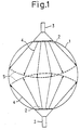
- Fig. 1 schematically shows the structure of an electron beam irradiation portion of a waste gas treatment apparatus for carrying out this waste gas treatment method.
- a waste gas duct 1 is provided with irradiation windows 2, and waste gas passing through the waste gas duct 1 is directly irradiated with electron beams 4 emitted from electron beam accelerators 3 through the irradiation window 2.
- the present invention is directed to solution of the above-described problems of the prior art and it is an object of the present invention to provide a method of and apparatus for treating waste gas by irradiation with electron beams, wherein a part of the waste gas taken from the main stream of waste gas is irradiated with electron beams using a low-voltage type accelerator to form active species such as O and OH radicals in the irradiated waste gas and to thereby activate it, the activated waste gas then being uniformly fed into the main stream of waste gas and thereby effectively removing noxious gas ingredients such as SO2 and NO x from the waste gas.
- the present invention provides a waste gas treatment method which comprises: irradiating a part of the waste gas which is the object of treatment with electron beams to form active species such as O and OH radicals in the irradiated waste gas; mixing the waste gas having the active species formed therein with the waste gas which is the object of treatment, thereby changing the noxious (gas) ingredients in the waste gas to be treated into the form of a mist or dust by the action of the active species: and capturing the mist or dust.
- the present invention also provides a waste gas treatment apparatus which comprises: an electron beam irradiation chamber for irradiation with electron beams from an electron beam accelerator; a feeding device which introduces a part of the waste gas to be treated into the electron beam irradiation chamber where the waste gas is irradiated with electron beams to thereby form active species such as O and OH radicals, and which feeds the waste gas having the active species formed herein to a waste gas main duct through which the waste gas to be treated is flowing; a dispersing device for uniformly dispersing in the waste gas main duct the waste gas fed thereinto from the feeding device; and a capturing device for capturing noxious (gas) ingredients in the waste gas within the main duct which have been changed into the form of a mist or dust by the action of the active species.
- a waste gas treatment apparatus which comprises: an electron beam irradiation chamber for irradiation with electron beams from an electron beam accelerator; a feeding device which introduces a part of the
- FIG. 2 schematically shows the structure of a waste gas treatment apparatus for carrying out the waste gas treatment method according to the present invention
- Fig. 3 is a sectional view taken along the line Y-Y of Fig. 2.
- An electron beam irradiation chamber 21 is disposed in the vicinity of a waste gas main duct 23.
- One end of the electron beam irradiation chamber 21 is commiunicated with the waste gas main duct 23 through a pipe line 22, while the other end thereof is communicated with a dispersing device 27 through a suction transfer blower 24, a pipe line 25 and an annular passage 26.
- the electron beam irradiation chamber 21 is provided with an electron beam accelerator 19.
- the distance from the electron beam irradiation opening of the electron beam accelerator 19 to the wall surface of the electron beam irradiation chamber 21 is set so as to be slightly greater than the maximum range of electron beams 20.
- the dispersing device 27 comprises a plurality of fins 28 that communicate with the annular passage 26 and blades 29 which are so disposed as to face the fins 28 and which rotate in the direction of the arrow 30.
- Each fin 28 has a multiplicity of small bores 31 formed in the reverse side thereof as viewed from the direction of the arrow 30, so that the vortex of waste gas 32 caused by the rotation of the blades 29 allows the waste gas irradiated with electron beams and delivered from the electron beam irradiation chamber 21 to be uniformly dispersed into and mixed with the waste gas 32.
- the reference numeral 33 denotes a motor for rotating the blades 29, while the numeral 34 denotes a support member for supporting the motor 33 within the waste gas main duct 23.
- the blades 29 are rotated by the motor 33
- the arrangement may, of course, be such that the driving section, for example, a motor, for rotating the blades 29 is provided outside the waste gas main duct 23 and the rotational force from the driving section is transmitted by appropriate rotational force transmission menas, for example, gears, chain or belt.
- the waste gas treatment apparatus By virtue of the above-described arrangement of the waste gas treatment apparatus, a part of the waste gas sucked in from the waste gas main duct 23 through the pipe line 22 is irradiated with the electron beams 20 from the electron beam accelerator 19, so that oxygen and water in the waste gas are formed into active species such as O and OH radicals.
- the waste gas having the active species formed therein is dispersed into and mixed with the waste gas 32 in the waste gas main duct 23 through the dispersing device 27.
- the active species act on noxious (gas) ingredients in the waste gas 32 to form mist or dust.
- each section of the waste gas treatment apparatus may have any specific disposition and structure, provided that the apparatus is arranged such that an electron beam irradiation chamber for irradiation with electron beams from an electron beam accelerator is provided in the vicinity of a main duct for waste gas: a part of the waste gas to be treated is introduced into the electron beam irradiation chamber where the waste gas is irradiated with electron beams to thereby form active species such as O and OH radicals; the waste gas having the active species formed therein is fed into the waste gas main duct by means of a feeding device; the waste gas fed into the waste gas main duct is dispersed into and mixed with the waste gas flowing through the main duct by means of a dispersing device, thereby changing noxious (gas) ingredients in the waste gas into the form of a mist or dust by the action of the active species
- a part of a waste gas is taken and irradiated with electron beams to form active species in the waste gas to thereby activate it, and the activated waste gas is then mixed with the gas which is object of treatment, thereby changing noxious (gas) ingredients in the waste gas into the form of a mist or dust. Therefore, it is unnecessary to directly irradiate all of the waste gas as in the prior art, and even if the amount of waste gas increases to the extent that would be expected if the treatment is applied on a practical scale and the size of the waste gas duct increases correspondingly, it is unnecessary to dispose a multiplicity of electron beam accelerators and raise the acceleration voltage.
- an electron beam accelerator and peripheral devices it is possible to markedly lower the installation cost of an electron beam accelerator and peripheral devices.
- the acceleration voltage of the electron beam accelerators it has heretofore been necessary to set the acceleration voltage of the electron beam accelerators at a high level, i.e., 800 kV or 1,000 kV, in order to obtain satisfactory electron beam energy in relation to the waste gas duct size or the like for the purpose of uniformly forming active species in the waste gas, whereas, in the case of the present invention, an electron beam accelerator with an acceleration voltage of about 300 kV suffices and it is therefore possible to markedly lower the installation cost of the electron beam accelerator and peripheral devices.
- the method and apparatus of the invention are suitable for utilization as a method and apparatus for treating waste gas such as boiler combustion waste gas in thermoelectric powder plants that use fossil fuels, for example, heavy oil or coal, as a fuel or sintering waste gas in iron works.
Abstract
Description
- The present invention relates to a method of and apparatus for treating waste gas wherein waste gas containing noxious (gas) ingredients such as SO₂ and NOx is irradiated with electron beams to change the noxious (gas) ingredients into the form of mist (sulfuric acid and/or nitric acid) or dust (ammonium sulfate and/or ammonium nitrate and the resulting mist or dust is then captured with a dust collector or the like.
- One method of waste gas treatment whereby noxious (gas) ingredients such as SO₂ and NOx are removed from waste gases is a method wherein waste gas is irradiated with electron beams to form various active species such as O and OH radicals from oxygen, water, etc. in the waste gas so that the active species act on the noxious (gas) ingredients in the waste gas such as to form mist and this mist is further changed into dust in the presence of ammonia or the like, the mist and dust then being captured with a dust collector or the like.
- Further, there is a technique disclosed in the JP-A-61-68126 wherein atmospheric air is introduced into an electron beam irradiation reactor to allow said air to be irradiated with electron beams to thereby form ozone and oxygen atoms therein. Said air having ozone and oxygen atoms is mixed with a waste gas to oxidise NO in the waste gas to form NO₂ and then the waste gas is introduced to a wet absorption tower to effect desulfurization and denitration.
- Fig. 1 schematically shows the structure of an electron beam irradiation portion of a waste gas treatment apparatus for carrying out this waste gas treatment method. As illustrated, a waste gas duct 1 is provided with
irradiation windows 2, and waste gas passing through the waste gas duct 1 is directly irradiated with electron beams 4 emitted fromelectron beam accelerators 3 through theirradiation window 2. In the structure wherein the electron beams 4 are directly applied to the inside of the waste gas duct 1, when the amount of waste gas increases to that which would be treated in a practical application and the size of the waste gas duct 1 increases correspondingly, it has heretofore been necessary, in order to allow all of the waste gas to absorb the electron beams 4, to dispose a multiplicity of electron beam accelerators 3 (two in the illustrated example) at the outer periphery of the waste gas duct 1 and also to increase the maximum range of the electron beams 4, as shown by thechain lines 5. However, disposition of a multiplicity ofelectron beam accelerators 3 involves disadvantage in that the structure of the waste gas treating apparatus becomes complicated and costs are raised. Further, in order to increase the maximum range of the electron beams 4, it is necessary to raise the acceleration voltage for electron beams, which leads to a substantial rise in the cost of theelectron beam accelerators 3. In addition, if electron beams are accelerated at high voltages, high-energy X-rays are generated and a thick concrete wall or the like must be provided in order to provide shielding from such high-energy X-rays, which results in a rise in the overall cost of the waste gas treatment apparatus. Thus, the prior art suffers from various problems. - It should be noted that there are techniques which aim to have all of the waste gas irradiated with electron beams at a uniform dose, including those disclosed in the JP-A-49-096975 and JP-A-55-097232 and US-A-4,507,265 and US-A-4,596,642, but none of them completely solves the above-described problems.
- The present invention is directed to solution of the above-described problems of the prior art and it is an object of the present invention to provide a method of and apparatus for treating waste gas by irradiation with electron beams, wherein a part of the waste gas taken from the main stream of waste gas is irradiated with electron beams using a low-voltage type accelerator to form active species such as O and OH radicals in the irradiated waste gas and to thereby activate it, the activated waste gas then being uniformly fed into the main stream of waste gas and thereby effectively removing noxious gas ingredients such as SO₂ and NOx from the waste gas.
- To attain the above-described object, the present invention provides a waste gas treatment method which comprises: irradiating a part of the waste gas which is the object of treatment with electron beams to form active species such as O and OH radicals in the irradiated waste gas; mixing the waste gas having the active species formed therein with the waste gas which is the object of treatment, thereby changing the noxious (gas) ingredients in the waste gas to be treated into the form of a mist or dust by the action of the active species: and capturing the mist or dust.
- The present invention also provides a waste gas treatment apparatus which comprises: an electron beam irradiation chamber for irradiation with electron beams from an electron beam accelerator; a feeding device which introduces a part of the waste gas to be treated into the electron beam irradiation chamber where the waste gas is irradiated with electron beams to thereby form active species such as O and OH radicals, and which feeds the waste gas having the active species formed herein to a waste gas main duct through which the waste gas to be treated is flowing; a dispersing device for uniformly dispersing in the waste gas main duct the waste gas fed thereinto from the feeding device; and a capturing device for capturing noxious (gas) ingredients in the waste gas within the main duct which have been changed into the form of a mist or dust by the action of the active species.
-
- Fig. 1 schematically shows the structure of an electron beam irradiation portion of a conventional waste gas treatment apparatus;
- Fig. 2 schematically shows the structure of a waste gas treatment apparatus for carrying out the waste gas treatment method according to the present invention; and
- Fig. 3 is a sectional view taken along the line Y-Y of Fig. 2;
- Modes for carrying out the present invention will be described hereinunder with reference to the drawings.
- Fig. 2 schematically shows the structure of a waste gas treatment apparatus for carrying out the waste gas treatment method according to the present invention, while Fig. 3 is a sectional view taken along the line Y-Y of Fig. 2.
- An electron
beam irradiation chamber 21 is disposed in the vicinity of a waste gasmain duct 23. One end of the electronbeam irradiation chamber 21 is commiunicated with the waste gasmain duct 23 through apipe line 22, while the other end thereof is communicated with a dispersing device 27 through asuction transfer blower 24, apipe line 25 and anannular passage 26. The electronbeam irradiation chamber 21 is provided with anelectron beam accelerator 19. The distance from the electron beam irradiation opening of theelectron beam accelerator 19 to the wall surface of the electronbeam irradiation chamber 21 is set so as to be slightly greater than the maximum range ofelectron beams 20. - The dispersing device 27 comprises a plurality of
fins 28 that communicate with theannular passage 26 and blades 29 which are so disposed as to face thefins 28 and which rotate in the direction of thearrow 30. Eachfin 28 has a multiplicity ofsmall bores 31 formed in the reverse side thereof as viewed from the direction of thearrow 30, so that the vortex ofwaste gas 32 caused by the rotation of the blades 29 allows the waste gas irradiated with electron beams and delivered from the electronbeam irradiation chamber 21 to be uniformly dispersed into and mixed with thewaste gas 32. It should be noted that, in the figures, thereference numeral 33 denotes a motor for rotating the blades 29, while thenumeral 34 denotes a support member for supporting themotor 33 within the waste gasmain duct 23. - It should be noted that although in the above-described example the blades 29 are rotated by the
motor 33, the arrangement may, of course, be such that the driving section, for example, a motor, for rotating the blades 29 is provided outside the waste gasmain duct 23 and the rotational force from the driving section is transmitted by appropriate rotational force transmission menas, for example, gears, chain or belt. - By virtue of the above-described arrangement of the waste gas treatment apparatus, a part of the waste gas sucked in from the waste gas
main duct 23 through thepipe line 22 is irradiated with theelectron beams 20 from theelectron beam accelerator 19, so that oxygen and water in the waste gas are formed into active species such as O and OH radicals. The waste gas having the active species formed therein is dispersed into and mixed with thewaste gas 32 in the waste gasmain duct 23 through the dispersing device 27. As a result, the active species act on noxious (gas) ingredients in thewaste gas 32 to form mist or dust. Thus it is possible to capture the mist or dust by means, for example, of a dust collector. - It should be noted that the structures of the waste gas treatment apparatus shown in Figs. 2 and 3 are one embodiment of the present invention and that the present invention is not necessarily limited thereto. In short, each section of the waste gas treatment apparatus may have any specific disposition and structure, provided that the apparatus is arranged such that an electron beam irradiation chamber for irradiation with electron beams from an electron beam accelerator is provided in the vicinity of a main duct for waste gas: a part of the waste gas to be treated is introduced into the electron beam irradiation chamber where the waste gas is irradiated with electron beams to thereby form active species such as O and OH radicals; the waste gas having the active species formed therein is fed into the waste gas main duct by means of a feeding device; the waste gas fed into the waste gas main duct is dispersed into and mixed with the waste gas flowing through the main duct by means of a dispersing device, thereby changing noxious (gas) ingredients in the waste gas into the form of a mist or dust by the action of the active species; and the mist or dust is captured by means of a capturing device, for example, a dust collector.
- As has been described above, according to the present invention, a part of a waste gas is taken and irradiated with electron beams to form active species in the waste gas to thereby activate it, and the activated waste gas is then mixed with the gas which is object of treatment, thereby changing noxious (gas) ingredients in the waste gas into the form of a mist or dust. Therefore, it is unnecessary to directly irradiate all of the waste gas as in the prior art, and even if the amount of waste gas increases to the extent that would be expected if the treatment is applied on a practical scale and the size of the waste gas duct increases correspondingly, it is unnecessary to dispose a multiplicity of electron beam accelerators and raise the acceleration voltage. Accordingly, it is possible to markedly lower the installation cost of an electron beam accelerator and peripheral devices. For example, in the conventional arrangement wherein electron beams are directly applied to waste gas, it has heretofore been necessary to set the acceleration voltage of the electron beam accelerators at a high level, i.e., 800 kV or 1,000 kV, in order to obtain satisfactory electron beam energy in relation to the waste gas duct size or the like for the purpose of uniformly forming active species in the waste gas, whereas, in the case of the present invention, an electron beam accelerator with an acceleration voltage of about 300 kV suffices and it is therefore possible to markedly lower the installation cost of the electron beam accelerator and peripheral devices.
- Thus, in the method of and apparatus for treating waste gas by irradiation with electron beams according to the present invention, noxious (gas) ingredients such as SO₂ and NOx in waste gas are changed into the form of a mist (sulfuric acid and/or nitric acid) or dust (ammonium sulfate and/or ammonium nitrate) and the resulting mist or dust is then captured with a dust collector or the like. Accordingly, the method and apparatus of the invention are suitable for utilization as a method and apparatus for treating waste gas such as boiler combustion waste gas in thermoelectric powder plants that use fossil fuels, for example, heavy oil or coal, as a fuel or sintering waste gas in iron works.
Claims (2)
- A method of treating waste gas whereby noxious gas ingredients such as SO₂ and NOx are removed from the waste gas comprising the steps(a) passing the waste gas to be treated through a main waste gas duct;(b) separating a part of the waste gas from the gas duct;(c) forming active species in the separated part of the waste gas by irradiating with electron beam;(d) mixing the separated part of the waste gas having the active species with the waste gas in the gas duct for changing the noxious gas ingredients into mist or dust; and(e) capturing the mist or dust by means of a dust collector.
- An apparatus for treating waste gas whereby noxious gas ingredients such as SO₂ and NOx are removed from the waste gas, specially designed for carrying out the method according to claim 1, comprising(a) a waste gas main duct (23) for gassing the waste gas to be treated;(b) an electron beam irradiation chamber (21) communicating at one end with the waste gas main duct (23) through a first pipeline (22) and at the other end with a dispersing device (27) disposed in the waste gas main duct (23) through a second pipeline (25);(c) a feeding device (24) for transferring a part of waste gas from the waste gas main duct (23) through the first pipeline, the electron irradiation chamber (21) and the second pipeline (25) to the dispersing device (27) for uniformly dispersing in the main duct (23) the part of waste gas fed from the feeding device (24) and changing the noxious gas ingredients into mist or dust; and(d) a dust collector for capturing the mist or dust.
Applications Claiming Priority (2)
| Application Number | Priority Date | Filing Date | Title |
|---|---|---|---|
| JP95666/86 | 1986-04-24 | ||
| JP61095666A JPS62250933A (en) | 1986-04-24 | 1986-04-24 | Exhaust gas treatment method and device using electron beam irradiation |
Publications (3)
| Publication Number | Publication Date |
|---|---|
| EP0308505A1 EP0308505A1 (en) | 1989-03-29 |
| EP0308505A4 EP0308505A4 (en) | 1989-06-26 |
| EP0308505B1 true EP0308505B1 (en) | 1993-06-09 |
Family
ID=14143816
Family Applications (1)
| Application Number | Title | Priority Date | Filing Date |
|---|---|---|---|
| EP87902748A Expired - Lifetime EP0308505B1 (en) | 1986-04-24 | 1987-04-23 | Method and device for flue gas treatment by irradiation with electron beams |
Country Status (5)
| Country | Link |
|---|---|
| US (2) | US5015443A (en) |
| EP (1) | EP0308505B1 (en) |
| JP (1) | JPS62250933A (en) |
| DE (1) | DE3786169T2 (en) |
| WO (1) | WO1987006494A1 (en) |
Families Citing this family (37)
| Publication number | Priority date | Publication date | Assignee | Title |
|---|---|---|---|---|
| JPS62250933A (en) * | 1986-04-24 | 1987-10-31 | Ebara Corp | Exhaust gas treatment method and device using electron beam irradiation |
| JPH0815532B2 (en) * | 1987-05-21 | 1996-02-21 | 三菱重工業株式会社 | Exhaust gas treatment method |
| WO1990004448A1 (en) * | 1988-10-28 | 1990-05-03 | Ebara Corporation | Method of and apparatus for treating waste gas by irradiation with electron beam |
| US5785866A (en) * | 1989-08-08 | 1998-07-28 | Osterreichisches Forschungszentrum Seibersdorf Gmbh | Process and apparatus for the treatment, in particular purification of water containing halogenated ethylenes |
| JPH0394813A (en) * | 1989-09-06 | 1991-04-19 | Japan Atom Energy Res Inst | Method for removing harmful gas in waste gas generated by incineration of refuse |
| DK0513080T3 (en) * | 1990-01-31 | 1994-09-26 | Ardenne Anlagentech Gmbh | Method and apparatus for treating castings of particulate material |
| US4985219A (en) * | 1990-02-14 | 1991-01-15 | Research-Cottrell, Inc. | Removal of nitrogen oxides from waste gases |
| US5219534A (en) * | 1991-04-26 | 1993-06-15 | Reynolds Warren D | Process and apparatus for decontaminating air |
| DK0540756T3 (en) * | 1991-05-21 | 1997-03-24 | Ebara Corp | Process and apparatus for removing SO2 and NOx from combustion flue gases |
| JPH0671134A (en) * | 1992-07-09 | 1994-03-15 | Toshiba Corp | Apparatus and method for removing carbon dioxide in exhaust gas |
| US5357291A (en) * | 1992-09-08 | 1994-10-18 | Zapit Technology, Inc. | Transportable electron beam system and method |
| US5378898A (en) * | 1992-09-08 | 1995-01-03 | Zapit Technology, Inc. | Electron beam system |
| US5457269A (en) * | 1992-09-08 | 1995-10-10 | Zapit Technology, Inc. | Oxidizing enhancement electron beam process and apparatus for contaminant treatment |
| US5319211A (en) * | 1992-09-08 | 1994-06-07 | Schonberg Radiation Corp. | Toxic remediation |
| WO1994017899A1 (en) * | 1993-02-05 | 1994-08-18 | Massachusetts Institute Of Technology | Tunable compact electron beam generated plasma system for the destruction of gaseous toxic compounds |
| US5370525A (en) * | 1993-03-22 | 1994-12-06 | Blue Pacific Environments Corporation | Microwave combustion enhancement device |
| IT1262524B (en) * | 1993-07-23 | 1996-07-02 | Marco Maltagliati | PROCEDURE FOR IMPROVING THE CHARACTERISTICS OF COMBUSTIBLE OILS, IN PARTICULAR OF BIOMASS PYROLYSIS OILS |
| US5561298A (en) * | 1994-02-09 | 1996-10-01 | Hughes Aircraft Company | Destruction of contaminants using a low-energy electron beam |
| JPH0847618A (en) * | 1994-06-03 | 1996-02-20 | Ebara Corp | Electron beam irradiation for waste gas treatment |
| US5807491A (en) * | 1996-08-29 | 1998-09-15 | Advanced Oxidation Systems, Inc. | Electron beam process and apparatus for the treatment of an organically contaminated inorganic liquid or gas |
| US6030506A (en) * | 1997-09-16 | 2000-02-29 | Thermo Power Corporation | Preparation of independently generated highly reactive chemical species |
| KR19990018051A (en) * | 1997-08-26 | 1999-03-15 | 김징완 | Flue gas treatment method by electron beam irradiation |
| JPH11137954A (en) * | 1997-11-10 | 1999-05-25 | Mitsubishi Heavy Ind Ltd | Treating device for waste gas from heavy oil fired boiler |
| KR20000009579A (en) | 1998-07-27 | 2000-02-15 | 박진규 | Harmful gas purifying method and device using vapor laser and electronic beam |
| US6623706B2 (en) | 2000-06-20 | 2003-09-23 | Advanced Electron Beams, Inc. | Air sterilizing system |
| US7189978B2 (en) * | 2000-06-20 | 2007-03-13 | Advanced Electron Beams, Inc. | Air sterilizing system |
| US6623705B2 (en) | 2000-06-20 | 2003-09-23 | Advanced Electron Beams, Inc. | Gas conversion system |
| KR100425550B1 (en) * | 2001-01-16 | 2004-04-03 | 학교법인 건국대학교 | System for removing voc by electron beam and method of the same |
| JP2004532403A (en) | 2001-03-20 | 2004-10-21 | アドバンスト・エレクトロン・ビームズ・インコーポレーテッド | Electron beam irradiation device |
| FI117852B (en) * | 2002-02-15 | 2007-03-30 | Bcde Group Waste Man Ltd Oy | Method, apparatus and singlet oxygen generator for purification of gases |
| US20060113486A1 (en) * | 2004-11-26 | 2006-06-01 | Valence Corporation | Reaction chamber |
| WO2006086645A1 (en) * | 2005-02-10 | 2006-08-17 | Northampton Community College | Method for the reduction of malodorous compounds |
| US20090188782A1 (en) * | 2007-10-01 | 2009-07-30 | Escrub Systems Incorporated | Wet-discharge electron beam flue gas scrubbing treatment |
| EP2448662B1 (en) * | 2009-06-03 | 2016-04-06 | Ixys Corporation | Methods and apparatuses for converting carbon dioxide and treating waste material |
| CN104722184B (en) * | 2013-12-18 | 2020-03-10 | 苏州鼎德电环保科技有限公司 | Washing tower, waste gas purification system comprising same and air purification method |
| CN106000039A (en) * | 2016-05-16 | 2016-10-12 | 长沙深湘通用机器有限公司 | Dry type ammonia desulphurization and denitration device |
| PL425063A1 (en) * | 2018-03-28 | 2019-10-07 | Instytut Chemii i Techniki Jądrowej | Method for simultaneous removal of acid inorganic impurities and volatile organic impurities from a stream of waste gases, preferably from the Diesel engine and method for removal of impurities |
Citations (1)
| Publication number | Priority date | Publication date | Assignee | Title |
|---|---|---|---|---|
| JPS577231A (en) * | 1980-06-16 | 1982-01-14 | Ebara Corp | Electron beam multistage irradiation type waste gas desulfurising and denitrating method and apparatus therefor |
Family Cites Families (19)
| Publication number | Priority date | Publication date | Assignee | Title |
|---|---|---|---|---|
| US4702808A (en) * | 1957-06-27 | 1987-10-27 | Lemelson Jerome H | Chemical reaction apparatus and method |
| US3869362A (en) * | 1973-01-11 | 1975-03-04 | Ebara Mfg | Process for removing noxious gas pollutants from effluent gases by irradiation |
| JPS5219832B2 (en) * | 1973-01-20 | 1977-05-31 | ||
| JPS5215265B2 (en) * | 1973-03-03 | 1977-04-27 | ||
| US3981815A (en) * | 1973-09-21 | 1976-09-21 | Ebara Manufacturing Co., Ltd. | Process for utilizing collected material removed from effluent gas |
| JPS518636A (en) * | 1974-07-09 | 1976-01-23 | Jei Kaningamu Ronarudo | |
| US4175016A (en) * | 1975-09-02 | 1979-11-20 | Texas Gas Transmission Corporation | Radiolytic-chemical method for production of gases |
| US4097349A (en) * | 1976-03-31 | 1978-06-27 | Stephen Zenty | Photochemical process for fossil fuel combustion products recovery and utilization |
| JPS5317566A (en) * | 1976-07-31 | 1978-02-17 | Kobe Steel Ltd | Denitration method for of exhaust gas |
| JPS5844009B2 (en) * | 1978-12-29 | 1983-09-30 | 株式会社荏原製作所 | Electron beam irradiation treatment method for exhaust gas and its equipment |
| JPS58884B2 (en) * | 1978-12-29 | 1983-01-08 | 株式会社荏原製作所 | Exhaust gas treatment method using radiation irradiation |
| JPS5772312A (en) * | 1980-10-24 | 1982-05-06 | Nippon Electric Co | Thin film condenser |
| US4372832A (en) * | 1981-01-21 | 1983-02-08 | Research-Cottrell, Incorporated | Pollution control by spray dryer and electron beam treatment |
| US4406762A (en) * | 1982-01-19 | 1983-09-27 | Research-Cottrell, Inc. | Electron beam coal desulfurization |
| FR2560067B1 (en) * | 1984-02-24 | 1989-04-07 | Vicarb Sa | METHOD AND DEVICE FOR UNIFYING, OR MAINTAINING, A CHEMICAL REACTION BY PHOTON EXCITATION |
| JPS6168126A (en) * | 1984-09-10 | 1986-04-08 | Ishikawajima Harima Heavy Ind Co Ltd | Wet method for desulfurizing and denitrating stack gas |
| DE3608291A1 (en) * | 1985-10-23 | 1987-04-23 | Licentia Gmbh | Process for the selective or simultaneous separation of pollutants from flue gases by irradiating the flue gases with electron beams |
| JPS62250933A (en) * | 1986-04-24 | 1987-10-31 | Ebara Corp | Exhaust gas treatment method and device using electron beam irradiation |
| DE3622621A1 (en) * | 1986-07-05 | 1988-01-14 | Kernforschungsz Karlsruhe | Process for purifying a flue gas stream from SO2 and NOx |
-
1986
- 1986-04-24 JP JP61095666A patent/JPS62250933A/en active Granted
-
1987
- 1987-04-23 EP EP87902748A patent/EP0308505B1/en not_active Expired - Lifetime
- 1987-04-23 DE DE8787902748T patent/DE3786169T2/en not_active Expired - Fee Related
- 1987-04-23 US US07/265,453 patent/US5015443A/en not_active Expired - Fee Related
- 1987-04-23 WO PCT/JP1987/000259 patent/WO1987006494A1/en active IP Right Grant
-
1988
- 1988-10-31 US US07/264,848 patent/US4915916A/en not_active Expired - Lifetime
Patent Citations (1)
| Publication number | Priority date | Publication date | Assignee | Title |
|---|---|---|---|---|
| JPS577231A (en) * | 1980-06-16 | 1982-01-14 | Ebara Corp | Electron beam multistage irradiation type waste gas desulfurising and denitrating method and apparatus therefor |
Also Published As
| Publication number | Publication date |
|---|---|
| JPS62250933A (en) | 1987-10-31 |
| US5015443A (en) | 1991-05-14 |
| EP0308505A1 (en) | 1989-03-29 |
| JPH0365210B2 (en) | 1991-10-11 |
| WO1987006494A1 (en) | 1987-11-05 |
| US4915916A (en) | 1990-04-10 |
| EP0308505A4 (en) | 1989-06-26 |
| DE3786169D1 (en) | 1993-07-15 |
| DE3786169T2 (en) | 1993-09-23 |
Similar Documents
| Publication | Publication Date | Title |
|---|---|---|
| EP0308505B1 (en) | Method and device for flue gas treatment by irradiation with electron beams | |
| US20100170779A1 (en) | Gas conversion system | |
| US4657738A (en) | Stack gas emissions control system | |
| JP3578215B2 (en) | Apparatus and method for detoxifying toxic substances | |
| CN1030025A (en) | Waste gas processing method | |
| RU2038131C1 (en) | Method for treatment of exhaust gas containing impurities of nitrogen and sulfur oxides | |
| US3997415A (en) | Process for removing sulfur dioxide and nitrogen oxides from effluent gases | |
| RU2113889C1 (en) | METHOD OF REMOVAL OF SO2 AND NOx FROM COMBUSTION PRODUCTS OF FUEL GASES AND DEVICE FOR REALIZATION OF THIS METHOD | |
| JP3431731B2 (en) | Electron beam irradiation exhaust gas treatment equipment | |
| CN1225035A (en) | Method and apparatus for treating gas by irradiation of electron beam | |
| CN106000039A (en) | Dry type ammonia desulphurization and denitration device | |
| CA1277953C (en) | Stack gas emissions control system | |
| CN114849434B (en) | Prilling tower system and tail gas treatment device | |
| WO1990004448A1 (en) | Method of and apparatus for treating waste gas by irradiation with electron beam | |
| EP0492167A2 (en) | Apparatus for desulfurizing exhaust gas | |
| WO1997001386A1 (en) | A method and apparatus for purifying a gaseous mixture including molecules and/or cells of toxic or polluting substances | |
| JPS61238325A (en) | Desulfurization and densitration apparatus of exhaust gas byelectron irradiation | |
| KR0133367Y1 (en) | Apparatus for treatment of exhaust gas using plasma | |
| EP0416631B1 (en) | Method for removing harmful gas from refuse combustion exhaust gas | |
| KR100229585B1 (en) | Method and apparatus of simultaneous removal of so2 & nox using electron beam cyclone reactor | |
| CN212369887U (en) | High-energy electron beam irradiation treatment reaction device | |
| JPH0616815B2 (en) | Method and apparatus for treating exhaust gas by electron beam irradiation | |
| EP0629430A1 (en) | Method for desulfurizing exhaust gas | |
| KR19990071259A (en) | Flue gas recycling method and device | |
| PL178279B1 (en) | Apparatus for removing undesirable gaseous contamination from a stream of industrial flue gases |
Legal Events
| Date | Code | Title | Description |
|---|---|---|---|
| PUAI | Public reference made under article 153(3) epc to a published international application that has entered the european phase |
Free format text: ORIGINAL CODE: 0009012 |
|
| 17P | Request for examination filed |
Effective date: 19880927 |
|
| AK | Designated contracting states |
Kind code of ref document: A1 Designated state(s): DE FR GB IT |
|
| A4 | Supplementary search report drawn up and despatched |
Effective date: 19890626 |
|
| 17Q | First examination report despatched |
Effective date: 19910326 |
|
| ITF | It: translation for a ep patent filed |
Owner name: INTERPATENT ST.TECN. BREV. |
|
| GRAA | (expected) grant |
Free format text: ORIGINAL CODE: 0009210 |
|
| AK | Designated contracting states |
Kind code of ref document: B1 Designated state(s): DE FR GB IT |
|
| REF | Corresponds to: |
Ref document number: 3786169 Country of ref document: DE Date of ref document: 19930715 |
|
| ET | Fr: translation filed | ||
| PLBE | No opposition filed within time limit |
Free format text: ORIGINAL CODE: 0009261 |
|
| STAA | Information on the status of an ep patent application or granted ep patent |
Free format text: STATUS: NO OPPOSITION FILED WITHIN TIME LIMIT |
|
| 26N | No opposition filed | ||
| REG | Reference to a national code |
Ref country code: GB Ref legal event code: IF02 |
|
| PGFP | Annual fee paid to national office [announced via postgrant information from national office to epo] |
Ref country code: FR Payment date: 20020312 Year of fee payment: 16 |
|
| PGFP | Annual fee paid to national office [announced via postgrant information from national office to epo] |
Ref country code: GB Payment date: 20020409 Year of fee payment: 16 |
|
| PGFP | Annual fee paid to national office [announced via postgrant information from national office to epo] |
Ref country code: DE Payment date: 20020628 Year of fee payment: 16 |
|
| PG25 | Lapsed in a contracting state [announced via postgrant information from national office to epo] |
Ref country code: GB Free format text: LAPSE BECAUSE OF NON-PAYMENT OF DUE FEES Effective date: 20030423 |
|
| PG25 | Lapsed in a contracting state [announced via postgrant information from national office to epo] |
Ref country code: DE Free format text: LAPSE BECAUSE OF NON-PAYMENT OF DUE FEES Effective date: 20031101 |
|
| GBPC | Gb: european patent ceased through non-payment of renewal fee |
Effective date: 20030423 |
|
| PG25 | Lapsed in a contracting state [announced via postgrant information from national office to epo] |
Ref country code: FR Free format text: LAPSE BECAUSE OF NON-PAYMENT OF DUE FEES Effective date: 20031231 |
|
| REG | Reference to a national code |
Ref country code: FR Ref legal event code: ST |
|
| PG25 | Lapsed in a contracting state [announced via postgrant information from national office to epo] |
Ref country code: IT Free format text: LAPSE BECAUSE OF NON-PAYMENT OF DUE FEES;WARNING: LAPSES OF ITALIAN PATENTS WITH EFFECTIVE DATE BEFORE 2007 MAY HAVE OCCURRED AT ANY TIME BEFORE 2007. THE CORRECT EFFECTIVE DATE MAY BE DIFFERENT FROM THE ONE RECORDED. Effective date: 20050423 |