EP0308385A2 - Adjustable guide for moving webs or fabrics - Google Patents
Adjustable guide for moving webs or fabrics Download PDFInfo
- Publication number
- EP0308385A2 EP0308385A2 EP88850305A EP88850305A EP0308385A2 EP 0308385 A2 EP0308385 A2 EP 0308385A2 EP 88850305 A EP88850305 A EP 88850305A EP 88850305 A EP88850305 A EP 88850305A EP 0308385 A2 EP0308385 A2 EP 0308385A2
- Authority
- EP
- European Patent Office
- Prior art keywords
- bellows
- bearing
- guide
- bearing housing
- frame
- Prior art date
- Legal status (The legal status is an assumption and is not a legal conclusion. Google has not performed a legal analysis and makes no representation as to the accuracy of the status listed.)
- Granted
Links
Images


Classifications
-
- B—PERFORMING OPERATIONS; TRANSPORTING
- B65—CONVEYING; PACKING; STORING; HANDLING THIN OR FILAMENTARY MATERIAL
- B65H—HANDLING THIN OR FILAMENTARY MATERIAL, e.g. SHEETS, WEBS, CABLES
- B65H23/00—Registering, tensioning, smoothing or guiding webs
- B65H23/02—Registering, tensioning, smoothing or guiding webs transversely
- B65H23/032—Controlling transverse register of web
- B65H23/038—Controlling transverse register of web by rollers
-
- B—PERFORMING OPERATIONS; TRANSPORTING
- B65—CONVEYING; PACKING; STORING; HANDLING THIN OR FILAMENTARY MATERIAL
- B65H—HANDLING THIN OR FILAMENTARY MATERIAL, e.g. SHEETS, WEBS, CABLES
- B65H23/00—Registering, tensioning, smoothing or guiding webs
- B65H23/02—Registering, tensioning, smoothing or guiding webs transversely
- B65H23/032—Controlling transverse register of web
-
- B—PERFORMING OPERATIONS; TRANSPORTING
- B65—CONVEYING; PACKING; STORING; HANDLING THIN OR FILAMENTARY MATERIAL
- B65H—HANDLING THIN OR FILAMENTARY MATERIAL, e.g. SHEETS, WEBS, CABLES
- B65H2555/00—Actuating means
- B65H2555/10—Actuating means linear
- B65H2555/11—Actuating means linear pneumatic, e.g. inflatable elements
Definitions
- the present invention concerns an adjustable guide for moving webs or fabrics.
- an apparatus arrangement has been used in controlling the lateral positioning of a moving web, wherein one end of the guide roll has been movable so that the bearing is guided laterally in horizontal direction for implementing displacement of the roll relative to the direction of travel of the web.
- the object of the invention is a guide for moving webs or fabrics which presents a compact, enclosed construction. Also an object of the invention is a guide comprising bellows associated with the bearing housing which are quickly replaceable by changing one complete package.
- the general object of the invention is also an apparatus design which is able to operate in any position, also upside down, and which thus may equally be used as a vertical guide.
- the guide of the invention is mainly characterized in that the guide comprises, within the bellows in the fluid space, a first bearing lug fixedly positioned relative to the fixed frame and thereon a pivot point, and a second bearing lug in fixed position relative to the movable bearing housing and thereon a pivot point, and that a curved arm has been fitted between said pivot points.
- the present invention teaches the forming of a guide construction of entirely novel type comprising a compact bellows structure which is replaceable as a unit, and therewithin suspension structures for a bearing housing, which consist of a bearing point located in a fixed position relative to the fixed frame and of a bearing point fixed relative to the movable bearing housing, between these a pivoted arm has been disposed to be turnable.
- a bearing housing which consist of a bearing point located in a fixed position relative to the fixed frame and of a bearing point fixed relative to the movable bearing housing, between these a pivoted arm has been disposed to be turnable.
- On either side of the bearing housing bellows of mutually identical structure have been disposed.
- the location of the pivot points may be different on the bellows.
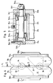
- a paper machine line is depicted, viewed from above.
- the direction of travel of the web W has been indicated with arrows L1.
- the guide of the invention has been disposed on both ends of the guide roll C of the paper web W.
- the guide 10 of the invention comprises, as shown in Fig. 2, a bearing housing 11 for the web guide roll.
- the bearing housing 11 comprises a bearing housing cover 12, which is detachably connectable to the frame of the bearing housing, advantageously with screw means (not depicted).
- a centric bearing space 14 of the bearing housing in which can be mounted the bearing, advantageously a spherical bearing, for the end journal of the guide roll.
- the guide of the invention comprises bellows on either side of the vertical central axis Y of the guide 10: a first bellows 17 and a second bellows 18.
- the guide 10 comprises, within the bearing housing 13, first bellows fixing means 15, for the first bellows 17, and second bellows fixing means 16 for the second bellows 18.
- the first bellows 17 is a unitary component, structurally comprising a first bellows section 17a and a second bellows section 17b.
- the second bellows on the other side of the central axis Y of the guide 10, comprises the first bellows section 18a and the second bellows section 18b of the second bellows 18.
- the bellows 17 and 18 consist advantageously of a resilient, elastic material.
- the first bellows 17 comprises, bounding on the resilient bellows section, and fixing the bellows section, a first fixing flange 19a1 and a second fixing flange 19a2.
- the first fixing flange 19a1 attaches to the bellows section 17a
- the second fixing flange 19a2 attaches to the bellows section 17b.
- the second bellows 18 comprises a first fixing flange 20a1, which attaches to the bellows section 18a, and a second fixing flange 20a2, which attaches to the bellows section 18b.
- a smaller diameter fixing member 19b1 which further attaches to the vertical frame section 21b of the frame 21, e.g. by screw means (not depicted).
- the fixing flange 19a2 comprises, associated with it, a smaller diameter fixing member 19b2, which is further detachably attachable to the frame 13 of the bearing housing, to its fixing section 15, advantageously likewise with similar screw means.
- Similar fixing members 20b1 and 20b2 are provided on the bellows component 18 for attaching the bellows 18 both to the bearing housing, to its frame 13, and to the vertical frame section 21c of the fixed frame 21.
- the first bellows 17 as well as the second bellows 18 have similar structural parts, and the bellows 17 and 18 are detachable for the duration of maintenance work from the frame section 13 and from the vertical frame section 21b and 21c of the fixed frame section 21. Therefore the bellows 17 and 18 together with the bearing means therein can be detached as a unit for the duration of maintenance work and replacement bellows can immediately be installed in their place, whereby web shut-downs are avoided.
- bellows 17 and 18 have equivalent structural components. As a result there are few different frame components, whereby the production costs will be lower.
- the guide 10 comprises a fixed frame 21, which comprises a horizontal frame section 21a and vertical frame sections 21b and 21c.
- the first bellows 17 attaches to the first vertical frame section 21b and the second bellows 18, to the second vertical frame section 21c.
- the first bellows 17 comprises a fluid space 31 therewithin, into which a pressurized fluid can be introduced for moving the bearing housing 11 horizontally.
- the second bearing housing 18 similarly comprises a fluid space 32, into which pressurized fluid, or vacuum, can be introduced for moving the bearing housing 11 in desired direction.
- the fluid pressure advantageously that of compressed air or of a hydraulic liquid, can be introduced into the pressurized fluid spaces 31 and/or 32 either of one bellows, 17 or 18, or of both bellows 17 and 18.
- the guide 10 comprises a first position measuring means 32, consisting substantially, as depicted in Fig. 2, of a horizontal rod component 23 which has been turnably pivoted with a bearing 24 to the frame 13 of the bearing housing 11.
- the position measuring means 22 further comprises a second rod 26, pivoted with the aid of a bearing 25 to the horizontal rod component 23.
- the vertical rod 26 is further connected to an angular position measuring means 27, this being for instance a potentiometer, which indicates the angular position of the rod 26 and, by this means, the position in horizontal direction of the bearing housing 11.
- the position information concerning the bearing housing can in this way be further transmitted to guide position remote control apparatus.
- the guide 10 further comprises a second detector means 28 registering the position of the bearing housing 11, consisting of a position pointer 29 fixed on the fixed frame 21 and of a scale 30 mounted on the frame 13 of the bearing housing 11 and moving along with the frame 13. At the pointer 29, the position of the bearing housing 11 is readable on the scale 30.
- first bellows 17 and the second bellows 18 are provided suspension means for the bearing housing 11, and they are equivalent as to their structural components in both bellows 17 and 18.
- the first bellows 17 contains a first bearing lug 33, located inside the first bellows 17, in its pressurized fluid space 31, this lug further attaching fixedly to the flange 19a1.
- a guide arm 37 has been placed within the pressurized fluid space 31, this arm connecting at one end with the pivot point of the first bearing lug 33, i.e., with the bearing 34, and at the other end with the pivot point 35 of the second bearing lug which is fixedly attached to the second flange 19a2, i.e., with the bearing 36.
- the arm 37 is thus turnably pivoted at both ends relative to the lugs 33 and 35.
- the second bellows 18 similarly contains equivalent structural components.
- a first lug 38 fixedly connected to the flange 20a2 and a second lug 40, fixedly connected to the flange 20a1.
- the first lug 38 comprises a pivot point, or bearing point, 39 for turnably pivoting the arm 42
- the second bearing lug 40 comprises a pivot point, or bearing point, 41 for turnably pivoting the other end of the arm 42.
- the pivot point 34 of the first lug 33 of the first bellows 17 is located above the longitudinal central axis X of the apparatus, and the pivot point 36 of the second lug 35 is correspondingly located below the central axis X.
- the pivot point 39 of the first lug 38 of the second bellows 18 is located above the central axis X, and the pivot point 41 of the second lug 40 is correspondingly located below the central axis X. Therefore, as depicted in Fig.
- the first bellows 17 is disposed in such position that the fixed lug 33 with its pivot point 34 lies below the central axis X and correspondingly the movable lug 35 with its movable pivot point 36 lies above the central axis X, that is if the bellows 17 is inverted, and if the apparatus arrangement regarding the bellows 18 is otherwise as in Fig. 2, the horizontal displacement of the roll centre will follow a convex path.
- the centre-point of the journal pin is positioned at the topmost point of the convex path, and then position of the journal pin centre descends on movement of the bearing housing 11 in either direction from the centre position.
- Fig. 4 is depicted the bellows design of Fig. 2, on larger scale.
- the figure shows the first bellows 17.
- the structural design is fully identical for the bellows 18, except that the location of the pivot points may be different depending on the position of the bellows, as has been described above.
- the entire bellows structure 17 is detachable as a unit for maintenance work, and the bellows structure 17 comprises a first bellows section 17a and a second bellows section 17b.
- a pressurized fluid space 31 Inside the bellows is provided a pressurized fluid space 31, into which pressurized fluid can be introduced through either or both flanges 19a1 and/or 19a2.
- With the first bellows section 17a connects the flange 19a1. It is further connected with the fixing component 19b1.
- the other half of the bellows is similar in construction. It comprises the bellows section 17b2, which connects with the flange 19a2.
- the flange 19a2 further comprises the fixing component 19b1.
- the bellows structure is enabled to be turned, in accordance with the intended use, so that the position relative to each other of the pivot points 36 and 34 can be changed with reference to the central axis X.
- To the flange 19a1 attaches fixedly a first bearing lug 33, comprising a pivot 34.
- To the flange 19a2 attaches fixedly a second bearing lug 35, which comprises the pivot 36.
- the bellows structure 17a,17b proper, surrounding the pressurized fluid space 31, consists of elastic, yielding material. advantageously of continuous material.
- the arm 37 comprises the arm section 37a proper and a sleeve part 37b on its end.
- the arm 37 has been placed between the first lug half 33a and second lug half of the lug 33.
- the pivot 34 comprises a bearing axle 34a having at one end an axle section 34c, which comprises threads 34c1, and at the other end is provided an axle section 34b, which comprises a cotter pin hole 34b1.
- the axle (34a,34b,34c) has been carried through the lug sections 33a and 33b and fixed with a cotter pin 34g relative to said lug portions.
- a nut 34d has been screwed on the thread 34c1 of the axle.
- bearing means 34e1 and 34e2 are advantageously conical roller bearings, whereby accurate and play-free rotation is obtained.
- the arm 37 turns relative to the axle 34a, carried by the bearings 34e1 and 34e2.
- the sleeve part 37b of the arm 37 furthermore carries a grease nipple 34f, through which said bearing means 34e1 and 34e2 can be provided with lubricant.
Abstract
Description
- The present invention concerns an adjustable guide for moving webs or fabrics.
- Heretofore, an apparatus arrangement has been used in controlling the lateral positioning of a moving web, wherein one end of the guide roll has been movable so that the bearing is guided laterally in horizontal direction for implementing displacement of the roll relative to the direction of travel of the web.
- Lateral guide bearings of moving webs are known in prior art in which both ends of the bearing housing comprise a bellows structure in which can be introduced fluid pressure in order to displace the bearing housing in desired direction. In apparatus designs of prior art said guide has been disposed to move horizontally on separate guide rails. A number of different bearing designs implementing horizontal movement are known in the art, but a major drawback of said bearings representing the state of art is that they tend to accumulate dirt, as the bearing means are open and unprotected.This is a great detriment particularly in the paper industry.
- The object of the invention is a guide for moving webs or fabrics which presents a compact, enclosed construction. Also an object of the invention is a guide comprising bellows associated with the bearing housing which are quickly replaceable by changing one complete package. The general object of the invention is also an apparatus design which is able to operate in any position, also upside down, and which thus may equally be used as a vertical guide.
- The guide of the invention is mainly characterized in that the guide comprises, within the bellows in the fluid space, a first bearing lug fixedly positioned relative to the fixed frame and thereon a pivot point, and a second bearing lug in fixed position relative to the movable bearing housing and thereon a pivot point, and that a curved arm has been fitted between said pivot points.
- The present invention teaches the forming of a guide construction of entirely novel type comprising a compact bellows structure which is replaceable as a unit, and therewithin suspension structures for a bearing housing, which consist of a bearing point located in a fixed position relative to the fixed frame and of a bearing point fixed relative to the movable bearing housing, between these a pivoted arm has been disposed to be turnable. On either side of the bearing housing bellows of mutually identical structure have been disposed. Merely the location of the pivot points may be different on the bellows.
- The invention is described, in the following, referring to certain advantageous embodiments of the invention, presented in the figures of the drawings attached hereto, yet to which the invention is not meant to be exclusively confined.
- In Fig. 1 are presented guides according to the invention, installed on the ends of the roll shaft. Here, the guide serves as a horizontal guide of the roll.
- In Fig. 2 is presented the guide of the invention in elevational view.
- In Fig. 3 the guide of the invention is presented, viewed in the direction of the arrow K₁ in Fig. 1.
- In Fig. 4 the bellows structure, dismountable as a unit, is shown in elevational view, the lugs and suspension shaft inside the bellows being indicated with interrupted lines.
- In Fig. 5 is presented the section I-I, as taken from Fig. 4 and viewed in the direction of the arrows.
- In Fig. 1, a paper machine line is depicted, viewed from above. The direction of travel of the web W has been indicated with arrows L₁. The guide of the invention has been disposed on both ends of the guide roll C of the paper web W.
- The
guide 10 of the invention comprises, as shown in Fig. 2, a bearinghousing 11 for the web guide roll. The bearinghousing 11 comprises a bearinghousing cover 12, which is detachably connectable to the frame of the bearing housing, advantageously with screw means (not depicted). Between theframe 13 of the bearing housing and thecover 12 of the bearing housing is defined a centric bearingspace 14 of the bearing housing, in which can be mounted the bearing, advantageously a spherical bearing, for the end journal of the guide roll. - The guide of the invention comprises bellows on either side of the vertical central axis Y of the guide 10: a
first bellows 17 and asecond bellows 18. Theguide 10 comprises, within the bearinghousing 13, first bellows fixing means 15, for thefirst bellows 17, and second bellows fixing means 16 for thesecond bellows 18. - The
first bellows 17 is a unitary component, structurally comprising afirst bellows section 17a and asecond bellows section 17b. - Similarly, the second bellows, on the other side of the central axis Y of the
guide 10, comprises thefirst bellows section 18a and thesecond bellows section 18b of thesecond bellows 18. Thebellows - The
first bellows 17 comprises, bounding on the resilient bellows section, and fixing the bellows section, a first fixing flange 19a₁ and a second fixing flange 19a₂. The first fixing flange 19a₁ attaches to thebellows section 17a, and the second fixing flange 19a₂ attaches to thebellows section 17b. - Similarly, the
second bellows 18 comprises a first fixing flange 20a₁, which attaches to thebellows section 18a, and a second fixing flange 20a₂, which attaches to thebellows section 18b. - Associated with the flange 19a₂ is a smaller diameter fixing member 19b₁, which further attaches to the
vertical frame section 21b of theframe 21, e.g. by screw means (not depicted). Similarly, the fixing flange 19a₂ comprises, associated with it, a smaller diameter fixing member 19b₂, which is further detachably attachable to theframe 13 of the bearing housing, to itsfixing section 15, advantageously likewise with similar screw means. - Similar fixing members 20b₁ and 20b₂ are provided on the
bellows component 18 for attaching thebellows 18 both to the bearing housing, to itsframe 13, and to thevertical frame section 21c of thefixed frame 21. - As taught by the invention, the
first bellows 17 as well as thesecond bellows 18 have similar structural parts, and thebellows frame section 13 and from thevertical frame section fixed frame section 21. Therefore thebellows - It is also essential that the
bellows - As depicted in Figs 2 and 3, the
guide 10 comprises afixed frame 21, which comprises ahorizontal frame section 21a andvertical frame sections first bellows 17 attaches to the firstvertical frame section 21b and thesecond bellows 18, to the secondvertical frame section 21c. - As further depicted with interrupted lines in Fig. 2, the
first bellows 17 comprises afluid space 31 therewithin, into which a pressurized fluid can be introduced for moving the bearinghousing 11 horizontally. The second bearinghousing 18 similarly comprises afluid space 32, into which pressurized fluid, or vacuum, can be introduced for moving the bearinghousing 11 in desired direction. For moving thebearing housing 11 horizontally, the fluid pressure, advantageously that of compressed air or of a hydraulic liquid, can be introduced into the pressurizedfluid spaces 31 and/or 32 either of one bellows, 17 or 18, or of bothbellows - The
guide 10 comprises a first position measuringmeans 32, consisting substantially, as depicted in Fig. 2, of ahorizontal rod component 23 which has been turnably pivoted with abearing 24 to theframe 13 of the bearinghousing 11. The position measuring means 22 further comprises asecond rod 26, pivoted with the aid of abearing 25 to thehorizontal rod component 23. Thevertical rod 26 is further connected to an angular position measuring means 27, this being for instance a potentiometer, which indicates the angular position of therod 26 and, by this means, the position in horizontal direction of the bearinghousing 11. The position information concerning the bearing housing can in this way be further transmitted to guide position remote control apparatus. - The
guide 10 further comprises a second detector means 28 registering the position of thebearing housing 11, consisting of aposition pointer 29 fixed on the fixedframe 21 and of ascale 30 mounted on theframe 13 of thebearing housing 11 and moving along with theframe 13. At thepointer 29, the position of the bearinghousing 11 is readable on thescale 30. - Within the
first bellows 17 and thesecond bellows 18 are provided suspension means for the bearinghousing 11, and they are equivalent as to their structural components in bothbellows - As depicted in Fig. 2, the
first bellows 17 contains a first bearinglug 33, located inside thefirst bellows 17, in itspressurized fluid space 31, this lug further attaching fixedly to the flange 19a₁. Similarly, aguide arm 37 has been placed within the pressurizedfluid space 31, this arm connecting at one end with the pivot point of the first bearinglug 33, i.e., with thebearing 34, and at the other end with thepivot point 35 of the second bearing lug which is fixedly attached to the second flange 19a₂, i.e., with thebearing 36. Thearm 37 is thus turnably pivoted at both ends relative to thelugs - The
second bellows 18 similarly contains equivalent structural components. Within thefluid space 32 inside thebellows 18 has been provided afirst lug 38 fixedly connected to the flange 20a₂ and asecond lug 40, fixedly connected to the flange 20a₁. Thefirst lug 38 comprises a pivot point, or bearing point, 39 for turnably pivoting thearm 42, and similarly the second bearinglug 40 comprises a pivot point, or bearing point, 41 for turnably pivoting the other end of thearm 42. - In the embodiment of the invention depicted in Figs 2 and 3, the
pivot point 34 of thefirst lug 33 of thefirst bellows 17 is located above the longitudinal central axis X of the apparatus, and thepivot point 36 of thesecond lug 35 is correspondingly located below the central axis X. In this embodiment of the invention thepivot point 39 of thefirst lug 38 of thesecond bellows 18 is located above the central axis X, and thepivot point 41 of thesecond lug 40 is correspondingly located below the central axis X. Therefore, as depicted in Fig. 2, when the bearinghousing 11 is moved out from its central axis Y in one direction or the other, themovable pivot point 36 on thebearing lug 35 in thepressurized fluid space 31 of thefirst bellows 17 will rise upward, and correspondingly themovable pivot point 39 on thebearing lug 38 in thepressurized fluid space 32 of thesecond bellows 18 will descend, and thus the centre of the journal pin of the roll in the bearinghousing 11 will remain in unchanged horizontal position. - If the
first bellows 17 is disposed in such position that thefixed lug 33 with itspivot point 34 lies below the central axis X and correspondingly themovable lug 35 with itsmovable pivot point 36 lies above the central axis X, that is if thebellows 17 is inverted, and if the apparatus arrangement regarding thebellows 18 is otherwise as in Fig. 2, the horizontal displacement of the roll centre will follow a convex path. In the centered position of theguide 10, when thearms housing 11 in either direction from the centre position. - Also conceivable is an embodiment of the invention in which the suspension means inside the
first bellows 17 are in the position depicted in Fig. 2 and the positioning of the suspension means of thebellows 18 is inverted so that thelug 38 attaching to thebearing housing 11, to itsframe 13, together with itspivot point 39 lies below the central axis X and correspondingly thelug 40 in fixed position relative to theframe 21, together with itspivot point 41, is located above the central axis. In that case the path of the roll shaft centre will be concave. When thearms housing 11 in either direction with the aid of fluid pressure supplied to either or bothbellows 17 and/or 18 causes the location of the centre of the roll's axis of rotation to rise upward. When no fluid pressure is applied to either one of thebellows housing 11 into centered position ; thus this design is self-centering. - In Fig. 4 is depicted the bellows design of Fig. 2, on larger scale. The figure shows the first bellows 17. The structural design is fully identical for the
bellows 18, except that the location of the pivot points may be different depending on the position of the bellows, as has been described above. The entire bellowsstructure 17 is detachable as a unit for maintenance work, and thebellows structure 17 comprises afirst bellows section 17a and asecond bellows section 17b. Inside the bellows is provided apressurized fluid space 31, into which pressurized fluid can be introduced through either or both flanges 19a₁ and/or 19a₂. With thefirst bellows section 17a connects the flange 19a₁. It is further connected with the fixing component 19b₁. The other half of the bellows is similar in construction. It comprises the bellows section 17b₂, which connects with the flange 19a₂. The flange 19a₂ further comprises the fixing component 19b₁. By devising the fixing components 19b₁ and 19b₂ and the mating coupling components (15,21b) connected with these to be similar, the bellows structure is enabled to be turned, in accordance with the intended use, so that the position relative to each other of the pivot points 36 and 34 can be changed with reference to the central axis X. To the flange 19a₁ attaches fixedly afirst bearing lug 33, comprising apivot 34. To the flange 19a₂ attaches fixedly asecond bearing lug 35, which comprises thepivot 36. On thepivot 34 has turnably been pivoted anarm 37, and the other end of thearm 37 has turnably been pivoted on thepivot 36. Thebellows structure pressurized fluid space 31, consists of elastic, yielding material. advantageously of continuous material. - In Fig. 3 is shown the section I-I from Fig. 4. The
arm 37 comprises thearm section 37a proper and asleeve part 37b on its end.Thearm 37 has been placed between the first lug half 33a and second lug half of thelug 33. Thepivot 34 comprises a bearingaxle 34a having at one end anaxle section 34c, which comprises threads 34c₁, and at the other end is provided anaxle section 34b, which comprises a cotter pin hole 34b₁. The axle (34a,34b,34c) has been carried through thelug sections 33a and 33b and fixed with acotter pin 34g relative to said lug portions. Anut 34d has been screwed on the thread 34c₁ of the axle. - Inside the
sleeve 37b of the arm, bearing means 34e₁ and 34e₂ have been provided. These bearing means are advantageously conical roller bearings, whereby accurate and play-free rotation is obtained. Thearm 37 turns relative to theaxle 34a, carried by the bearings 34e₁ and 34e₂. Thesleeve part 37b of thearm 37 furthermore carries agrease nipple 34f, through which said bearing means 34e₁ and 34e₂ can be provided with lubricant.
Claims (5)
Priority Applications (1)
| Application Number | Priority Date | Filing Date | Title |
|---|---|---|---|
| AT88850305T ATE70250T1 (en) | 1987-09-18 | 1988-09-16 | ADJUSTABLE GUIDE FOR MOVING PANELS OR FABRIC PANELS. |
Applications Claiming Priority (2)
| Application Number | Priority Date | Filing Date | Title |
|---|---|---|---|
| FI874092A FI77434C (en) | 1987-09-18 | 1987-09-18 | REGLERBART STYRORGAN FOER ROERLIGA BANOR ELLER VAEVNADER. |
| FI874092 | 1987-09-18 |
Publications (3)
| Publication Number | Publication Date |
|---|---|
| EP0308385A2 true EP0308385A2 (en) | 1989-03-22 |
| EP0308385A3 EP0308385A3 (en) | 1989-05-24 |
| EP0308385B1 EP0308385B1 (en) | 1991-12-11 |
Family
ID=8525086
Family Applications (1)
| Application Number | Title | Priority Date | Filing Date |
|---|---|---|---|
| EP88850305A Expired - Lifetime EP0308385B1 (en) | 1987-09-18 | 1988-09-16 | Adjustable guide for moving webs or fabrics |
Country Status (5)
| Country | Link |
|---|---|
| US (1) | US4932578A (en) |
| EP (1) | EP0308385B1 (en) |
| AT (1) | ATE70250T1 (en) |
| DE (1) | DE3866840D1 (en) |
| FI (1) | FI77434C (en) |
Cited By (1)
| Publication number | Priority date | Publication date | Assignee | Title |
|---|---|---|---|---|
| WO2002073048A1 (en) * | 2001-01-29 | 2002-09-19 | Voith Paper Patent Gmbh | Improved adjustable bearing for side guiding continuous belts, and a method for replacing wear components thereof |
Families Citing this family (2)
| Publication number | Priority date | Publication date | Assignee | Title |
|---|---|---|---|---|
| FI94781C (en) * | 1993-01-29 | 1995-10-25 | Valmet Paper Machinery Inc | Paper machine fabric guide device |
| WO2000053369A1 (en) * | 1999-03-09 | 2000-09-14 | Ronald Melvin Gilbertson | Air switch and palm guide for papermaking machinery |
Citations (4)
| Publication number | Priority date | Publication date | Assignee | Title |
|---|---|---|---|---|
| DE1298783B (en) * | 1961-09-14 | 1969-07-03 | Ind Ovens Inc | Device for automatically guiding and centering a moving track |
| DE2305689B2 (en) * | 1972-03-01 | 1975-10-02 | Rockford Servo Corp., Rockford, Ill. (V.St.A.) | Device for the lateral guidance of a moving web |
| US4655378A (en) * | 1984-07-25 | 1987-04-07 | Dufour Kenneth S | Differential pressure biased spool type valve controller for a pneumatic dual diaphragm control system |
| DE3540881A1 (en) * | 1985-11-18 | 1987-06-04 | Windmoeller & Hoelscher | DEVICE FOR CONTROLLING THE POSITION OF RAILWAYS OR CONVEYOR BELTS RELATIVE TO THEIR GUIDE OR ROLLER ROLLERS |
Family Cites Families (6)
| Publication number | Priority date | Publication date | Assignee | Title |
|---|---|---|---|---|
| BE549133A (en) * | ||||
| US3101005A (en) * | 1960-03-26 | 1963-08-20 | Voith Gmbh J M | Belt-aligning structure |
| US3750920A (en) * | 1971-04-05 | 1973-08-07 | Gilbert & Nash Co Inc | Web guide |
| US3841722A (en) * | 1972-03-16 | 1974-10-15 | Tampella Oy Ab | Automatic guide for roll |
| US3966106A (en) * | 1974-07-24 | 1976-06-29 | Dominion Engineering Works, Limited | Follower roll suspension system |
| US4610739A (en) * | 1984-11-02 | 1986-09-09 | Adolph Coors Company | Method and device for providing longitudinal and lateral stretch control in laminated webs |
-
1987
- 1987-09-18 FI FI874092A patent/FI77434C/en not_active IP Right Cessation
-
1988
- 1988-09-14 US US07/244,501 patent/US4932578A/en not_active Expired - Lifetime
- 1988-09-16 DE DE8888850305T patent/DE3866840D1/en not_active Expired - Fee Related
- 1988-09-16 EP EP88850305A patent/EP0308385B1/en not_active Expired - Lifetime
- 1988-09-16 AT AT88850305T patent/ATE70250T1/en not_active IP Right Cessation
Patent Citations (4)
| Publication number | Priority date | Publication date | Assignee | Title |
|---|---|---|---|---|
| DE1298783B (en) * | 1961-09-14 | 1969-07-03 | Ind Ovens Inc | Device for automatically guiding and centering a moving track |
| DE2305689B2 (en) * | 1972-03-01 | 1975-10-02 | Rockford Servo Corp., Rockford, Ill. (V.St.A.) | Device for the lateral guidance of a moving web |
| US4655378A (en) * | 1984-07-25 | 1987-04-07 | Dufour Kenneth S | Differential pressure biased spool type valve controller for a pneumatic dual diaphragm control system |
| DE3540881A1 (en) * | 1985-11-18 | 1987-06-04 | Windmoeller & Hoelscher | DEVICE FOR CONTROLLING THE POSITION OF RAILWAYS OR CONVEYOR BELTS RELATIVE TO THEIR GUIDE OR ROLLER ROLLERS |
Cited By (1)
| Publication number | Priority date | Publication date | Assignee | Title |
|---|---|---|---|---|
| WO2002073048A1 (en) * | 2001-01-29 | 2002-09-19 | Voith Paper Patent Gmbh | Improved adjustable bearing for side guiding continuous belts, and a method for replacing wear components thereof |
Also Published As
| Publication number | Publication date |
|---|---|
| DE3866840D1 (en) | 1992-01-23 |
| FI77434C (en) | 1989-03-10 |
| FI874092A0 (en) | 1987-09-18 |
| EP0308385A3 (en) | 1989-05-24 |
| EP0308385B1 (en) | 1991-12-11 |
| US4932578A (en) | 1990-06-12 |
| ATE70250T1 (en) | 1991-12-15 |
| FI77434B (en) | 1988-11-30 |
Similar Documents
| Publication | Publication Date | Title |
|---|---|---|
| US5971404A (en) | Self-centering suspension for in-pipe use | |
| FI94067C (en) | Calendar | |
| US4741607A (en) | Supporting device for an optical observation instrument | |
| JP3363183B2 (en) | Dewatering foil device for paper machine | |
| CA1139551A (en) | Caliper gauge for the measurement of sheet members over a wide range of thicknesses | |
| US5906305A (en) | Apparatus for the corrective positioning of a travelling web at right angles to the direction of travel | |
| CA1094350A (en) | Vibratory device | |
| SE513776C2 (en) | Folding tool, process for its manufacture and use of this tool | |
| EP0308385B1 (en) | Adjustable guide for moving webs or fabrics | |
| DE2815228C3 (en) | Test arrangement for the non-destructive testing of metallic test material | |
| US4909450A (en) | Roller mill | |
| DE19706291B4 (en) | Contour measuring device with a feeler pin | |
| EP0485042B1 (en) | Measuring device for registration of pendulum angle | |
| EP0060483A1 (en) | Manipulator robot | |
| EP0173010A2 (en) | Device for mechanically measuring and for controlling the tractive force of a motor tractor | |
| US4966653A (en) | Apparatus for controlling a moving band | |
| CN210646234U (en) | Feeding device of drum mixer | |
| US6627044B2 (en) | Web guide in a paper machine/board machine | |
| DE4402787C2 (en) | Vibration deflection angle measuring device for a low-swing deflection crane operation | |
| CN113790024B (en) | Anchor bores arm levelling device | |
| US4587742A (en) | Scale balancing device in universal parallel ruler device | |
| FI62258C (en) | DRAG- OCH STOETANORDNING | |
| CN213629647U (en) | Position adjusting device and chassis device | |
| GB2285965A (en) | Grab device | |
| DE2361342C2 (en) | Device for monitoring the unbalance on pendulum centrifuges |
Legal Events
| Date | Code | Title | Description |
|---|---|---|---|
| PUAI | Public reference made under article 153(3) epc to a published international application that has entered the european phase |
Free format text: ORIGINAL CODE: 0009012 |
|
| AK | Designated contracting states |
Kind code of ref document: A2 Designated state(s): AT CH DE ES FR GB IT LI SE |
|
| PUAL | Search report despatched |
Free format text: ORIGINAL CODE: 0009013 |
|
| AK | Designated contracting states |
Kind code of ref document: A3 Designated state(s): AT CH DE ES FR GB IT LI SE |
|
| 17P | Request for examination filed |
Effective date: 19890703 |
|
| 17Q | First examination report despatched |
Effective date: 19901214 |
|
| GRAA | (expected) grant |
Free format text: ORIGINAL CODE: 0009210 |
|
| AK | Designated contracting states |
Kind code of ref document: B1 Designated state(s): AT CH DE ES FR GB IT LI SE |
|
| PG25 | Lapsed in a contracting state [announced via postgrant information from national office to epo] |
Ref country code: IT Free format text: LAPSE BECAUSE OF FAILURE TO SUBMIT A TRANSLATION OF THE DESCRIPTION OR TO PAY THE FEE WITHIN THE PRESCRIBED TIME-LIMIT;WARNING: LAPSES OF ITALIAN PATENTS WITH EFFECTIVE DATE BEFORE 2007 MAY HAVE OCCURRED AT ANY TIME BEFORE 2007. THE CORRECT EFFECTIVE DATE MAY BE DIFFERENT FROM THE ONE RECORDED. Effective date: 19911211 Ref country code: LI Effective date: 19911211 Ref country code: ES Free format text: THE PATENT HAS BEEN ANNULLED BY A DECISION OF A NATIONAL AUTHORITY Effective date: 19911211 Ref country code: FR Effective date: 19911211 Ref country code: CH Effective date: 19911211 |
|
| REF | Corresponds to: |
Ref document number: 70250 Country of ref document: AT Date of ref document: 19911215 Kind code of ref document: T |
|
| REF | Corresponds to: |
Ref document number: 3866840 Country of ref document: DE Date of ref document: 19920123 |
|
| REG | Reference to a national code |
Ref country code: CH Ref legal event code: PL |
|
| EN | Fr: translation not filed | ||
| PG25 | Lapsed in a contracting state [announced via postgrant information from national office to epo] |
Ref country code: GB Effective date: 19920916 Ref country code: AT Effective date: 19920916 |
|
| PG25 | Lapsed in a contracting state [announced via postgrant information from national office to epo] |
Ref country code: SE Effective date: 19920917 |
|
| PLBE | No opposition filed within time limit |
Free format text: ORIGINAL CODE: 0009261 |
|
| STAA | Information on the status of an ep patent application or granted ep patent |
Free format text: STATUS: NO OPPOSITION FILED WITHIN TIME LIMIT |
|
| 26N | No opposition filed | ||
| GBPC | Gb: european patent ceased through non-payment of renewal fee |
Effective date: 19920916 |
|
| PG25 | Lapsed in a contracting state [announced via postgrant information from national office to epo] |
Ref country code: DE Effective date: 19930602 |
|
| EUG | Se: european patent has lapsed |
Ref document number: 88850305.9 Effective date: 19930406 |