EP0307236B1 - Adaptive welding control vision head - Google Patents
Adaptive welding control vision headInfo
- Publication number
- EP0307236B1 EP0307236B1 EP88308367A EP88308367A EP0307236B1 EP 0307236 B1 EP0307236 B1 EP 0307236B1 EP 88308367 A EP88308367 A EP 88308367A EP 88308367 A EP88308367 A EP 88308367A EP 0307236 B1 EP0307236 B1 EP 0307236B1
- Authority
- EP
- European Patent Office
- Prior art keywords
- enclosure
- workpiece
- aperture
- lens
- welding
- Prior art date
- Legal status (The legal status is an assumption and is not a legal conclusion. Google has not performed a legal analysis and makes no representation as to the accuracy of the status listed.)
- Expired - Lifetime
Links
- 238000003466 welding Methods 0.000 title claims description 42
- 230000003044 adaptive effect Effects 0.000 title claims description 15
- 238000012544 monitoring process Methods 0.000 claims description 11
- 239000002184 metal Substances 0.000 claims description 9
- 239000002245 particle Substances 0.000 claims description 9
- 230000000007 visual effect Effects 0.000 claims description 6
- 239000011248 coating agent Substances 0.000 claims description 5
- 238000000576 coating method Methods 0.000 claims description 5
- 238000001816 cooling Methods 0.000 claims description 5
- 239000000835 fiber Substances 0.000 claims description 2
- 230000001012 protector Effects 0.000 claims 2
- 230000003287 optical effect Effects 0.000 description 11
- 239000003517 fume Substances 0.000 description 5
- 238000000034 method Methods 0.000 description 4
- 239000007789 gas Substances 0.000 description 3
- 238000004140 cleaning Methods 0.000 description 2
- 238000010586 diagram Methods 0.000 description 2
- 239000002923 metal particle Substances 0.000 description 2
- 230000001681 protective effect Effects 0.000 description 2
- 238000009825 accumulation Methods 0.000 description 1
- 238000004458 analytical method Methods 0.000 description 1
- 238000011109 contamination Methods 0.000 description 1
- 239000002826 coolant Substances 0.000 description 1
- 239000006185 dispersion Substances 0.000 description 1
- 239000000428 dust Substances 0.000 description 1
- 239000011521 glass Substances 0.000 description 1
- 239000011261 inert gas Substances 0.000 description 1
- 238000004519 manufacturing process Methods 0.000 description 1
- XLYOFNOQVPJJNP-UHFFFAOYSA-N water Substances O XLYOFNOQVPJJNP-UHFFFAOYSA-N 0.000 description 1
Images


Classifications
-
- B—PERFORMING OPERATIONS; TRANSPORTING
- B23—MACHINE TOOLS; METAL-WORKING NOT OTHERWISE PROVIDED FOR
- B23K—SOLDERING OR UNSOLDERING; WELDING; CLADDING OR PLATING BY SOLDERING OR WELDING; CUTTING BY APPLYING HEAT LOCALLY, e.g. FLAME CUTTING; WORKING BY LASER BEAM
- B23K9/00—Arc welding or cutting
- B23K9/095—Monitoring or automatic control of welding parameters
- B23K9/0956—Monitoring or automatic control of welding parameters using sensing means, e.g. optical
Definitions
- Robot vision systems are becoming very important in the application of adaptive control of automated welding systems.
- a serious problem which these systems must overcome is the harshness of the welding environment.
- Optical equipment used in adaptive control of the welding process is at a high risk of being damaged or rendered useless because of the spatter of particles of molten metal which are projected outward from the welding arc, fumes from the welding process that can leave a sooty residue on optical lenses and heat from the arc that can distort optical equipment.
- EP-A1-0 179 505 describes a device for protecting optical means from contaminated gases, in which a laminar gas flow is passed over the outer surface of a window to prevent aggresive gases and oxides from reaching the outer surface of the window.
- a vision sensor including a television camera is housed in a rugged enclosure where a dust-free, constant temperature and positive air pressure environment is maintained.
- a further object of the present invention is to provide a device to protect the optical equipment from the flying particles, fumes and heat of the welding process.
- a vision head to supply the electrical signals required for visual control of an adaptive welding control system with a welding head, which produces a weld pool on a workpiece being welded, comprising: a metal enclosure for attachment to the welding head having a side facing the workpiece, the said side slanting away from the said welding head so as to form an angle with a plane tangent to the workpiece and passing through the weld pool, projecting means mounted in said enclosure for projecting a structured light pattern onto the workpiece, monitoring means mounted in said enclosure for monitoring scattered light of the said structured light pattern on the workpiece and converting said scattered light into electrical signals required for visual control; characterised in that the side of the enclosure has an antispatter oil coating, a first aperture through which the structured light pattern is projected onto the workpiece and a second aperture through which the scattered light is monitored, the first aperture being a slit up to 30 mm long and from 0.5 to 2 mm wide and the second aperture being a hole from 0.5 to 2 mm in diameter, and
- One embodiment of the present invention provides for a vision head to supply the signals required for visual control of an adaptive welding control system.
- Said vision head comprises a metal enclosure for attachment to a welding head.
- the welding head produces a welding pool of molten metal on the workpiece.
- Said enclosure has a side facing a workpiece, the said side slanting away from the welding head so as to form an angle with a plane tangent to the workpiece and passing through said weld pool, said side having a first and second aperture.
- the range of angles found to give the preferred results was from 5° to 45°.
- Mounted in the metal enclosure is a projecting means for projecting a structured light pattern onto the workpiece through the first aperture.
- the vision head also includes a pressurizing means for maintaining a positive air pressure in the enclosure and a cooling means for maintaining the temperature of the enclosure.
- the external surface of the side facing the enclosure is covered with an oil coating to prevent particles of molten metal thrown from the welding torch from adhering to the surface.
- Figure 1 shows a cross-section of the vision head.
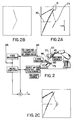
- Figure 2 is a block diagram of the adaptive welding control system.
- Figure 3 shows the advantage of the particular geometry of the vision head.
- Figure 1 shows a cross-section of the vision head.
- the side 1 of the enclosure 4 facing the workpiece 17 is slanted away from the welding head 15 so as to form an angle of 14° with the plane 18 tangent to the workpiece 17 passing through the weld pool 16.
- first aperture 10 and second aperture 11 are oriented perpendicular to the said side 1.
- the external surface of the said side 1 is covered with an oil coating 19 which is the same as the antispatter coating commonly used in the protection of welding heads.
- a projecting means 20 is mounted in the enclosure 4 so that a light pattern 22 of well defined geometry, in this case a line, can be projected onto the workpiece.
- the projecting means 20 comprises a light source 7 which projects through a cylindrical lens 8 and a protective plate 9 to protect the lens from foreign particles, and finally through the first aperture 10 which is 0.5 mm by 15 mm and onto the workpiece 17.
- the light source 7 can be selected from the group consisting of a fiber optic bundle and a laser diode.
- the range of dimensions for the first aperture 10 is up to 30 mm in length and from 0.5 mm to 2.0 mm in width.
- a monitoring means 21 for monitoring the scattered light 23 of the structured light pattern 22 after it has struck the workpiece 17.
- the scattered light 23 passes through the second aperture 11 which has a diameter of 1.5 mm and passes through a protective plate 12 which prevents any particles thrown from the welding torch 15 from striking the lens 2.
- the range of dimensions for the second aperture 11 is from 0.5 mm to 2.0 mm in diameter.
- the scattered light 23 then passes through a precision lens 2 and then through an interference filter 3 which prevents light other than the scattered light of the projected light source from passing to the detector 5 which is a two dimensional array charge coupled device mounted in the enclosure to convert the scattered light images 23 into electrical signals.
- a printed circuit 6 transmits the electrical signals to the adaptive welding control system.
- the arrangement of the second aperture 11, lens 2 and filter 3 are such that they form a telecentric configuration. This configuration ensures complete collimation of the light before it reaches the filter 3. This prevents vignetting and permits the use of a 2.5 nanometer as opposed to the usual 10 nanometer filter.
- the minimum distance 30 between the second aperture 11 the the lens 2 should be small enough to give a sufficiently wide field of vision and great enough to allow for the dispersion of flying metal particles that may find their way through the second aperture. This distance has been found to be from 10 to 40 mm with 20 mm giving the preferred results. This will ensure that the most probable point of impact 40 of any small metal particle will occur on that part of the lens 2 that is least used.
- a connection 13 for air provides a pressurizing means by allowing air to flow into the enclosure 4 at an approximate rate of 3 liters per minute and results in a small positive air pressure within the enclosure 4 which prevents fumes from entering the enclosure 4 through the apertures 10 and 11.
- the direction 50 of the air flow resulting from the small internal positive air pressure is away from the welding arc and its surrounding weld pool inert gas shield 60.
- the air pressure is used to protect the optical equipment from fumes and not to stop spatters.
- a connection 14 for cooling provides a cooling means.
- the flow of coolant usually water, prevents heat accumulation in the enclosure.
- FIG 2 is a block diagram of the adaptive control system.
- the light source 45 mounted in the enclosure 65 projects a structured light pattern 95 onto the workpiece 75.
- the scattered light 85 is sensed by the monitoring means 55 which produces a typical image as seen in block A of Figure 2.
- At the centre of block A is the characteristic angle joint profile 25.
- the image is distorted by a spot 35 at the left caused by the light from the welding arc and by the trace 15 of two particles of molten metal which have crossed the field of vision.
- the image is sent to the video processor for analysis.
- Block B shows the digitized profile generated in real time by the video processor from the video signal supplied by the monitoring means 55.
- the processor transmits its results to the micro-computer which performs the calculations required to provide the welding parameters: position and orientation of the joint, distance between edges etc.
- Block C shows a cross indicating the calculated centre of the weld joint.
Landscapes
- Engineering & Computer Science (AREA)
- Physics & Mathematics (AREA)
- Plasma & Fusion (AREA)
- Mechanical Engineering (AREA)
- Length Measuring Devices By Optical Means (AREA)
- Laser Beam Processing (AREA)
Description
- Robot vision systems are becoming very important in the application of adaptive control of automated welding systems. A serious problem which these systems must overcome is the harshness of the welding environment. Optical equipment used in adaptive control of the welding process is at a high risk of being damaged or rendered useless because of the spatter of particles of molten metal which are projected outward from the welding arc, fumes from the welding process that can leave a sooty residue on optical lenses and heat from the arc that can distort optical equipment.
- Methods of protecting optical equipment in environments of high temperature and flying particles are mentioned in United States patent no. 3,321,265 issued May 23, 1967 to Serge and Marcel Clavé, and United States patent no. 3,310,356 issued March 21, 1967 to Willy Borberg. These patents are examples of specific enclosures used to protect optical equipment. Another example is found in United States patent no. 4,450,339 issued May 22, 1984 to Nelson R. Corby, Jr. These patents do not provide for the projection of a light which is required of an active vision system. United States patent no. 4,497,996 issued February 5, 1985 to Charles J. Libby, Jr. provides for the projection of light but is constructed in such a way that it would require frequent cleaning.
- Technische Rundschau, volume 77, no. 34, August 1985, Bern, pages 45-51, 53 and 55; P. Drew et al. "Sensoren für das Lichtbogen-schweissen mit Handhabungssystemen" describes a sensor for an adaptive welding control system, in which the vision head is positioned in front of the welding head to protect it from damage or contamination by dust and spatters.
- EP-A1-0 179 505 describes a device for protecting optical means from contaminated gases, in which a laminar gas flow is passed over the outer surface of a window to prevent aggresive gases and oxides from reaching the outer surface of the window.
- Technisches Messen T.M. volume 51,
nos 7/8, July/August 1984, München, pages 270-275, P. Drew et. al. "Optisch-elektronischer Nahtführungssensor zur Schweissnahtverfolgung" describes an optical sensor for seam tracking in an automated arc welding system. - Welding and Metal Fabrication volume 51, no. 6, July/August 1983, Haywards Heath, Sussex G.B., page 260 "The Robot's other half" describes an optical sensor for an adaptive welding system which is protected from fumes and spatter by means of a filtered air stream and two replaceable shielding glasses.
- Welding Journal
volume 65, no. 11, November 1986, Miami, FL, U.S.A., pages 33-41; J. E. Agapakis et. al. "Joint tracking and adaptive robotic welding using vision sensing of the weld joint geometry" describes an adaptive welding control system. A vision sensor including a television camera is housed in a rugged enclosure where a dust-free, constant temperature and positive air pressure environment is maintained. - It is the object of the present invention to provide a device which will allow optical equipment, in the form of a light source and a light monitor, to be attached to the welding head and be such as to require infrequent cleaning.
- A further object of the present invention is to provide a device to protect the optical equipment from the flying particles, fumes and heat of the welding process.
- According to the present invention there is provided a vision head to supply the electrical signals required for visual control of an adaptive welding control system with a welding head, which produces a weld pool on a workpiece being welded, comprising:
a metal enclosure for attachment to the welding head having a side facing the workpiece, the said side slanting away from the said welding head so as to form an angle with a plane tangent to the workpiece and passing through the weld pool,
projecting means mounted in said enclosure for projecting a structured light pattern onto the workpiece,
monitoring means mounted in said enclosure for monitoring scattered light of the said structured light pattern on the workpiece and converting said scattered light into electrical signals required for visual control;
characterised in that the side of the enclosure has an antispatter oil coating, a first aperture through which the structured light pattern is projected onto the workpiece and a second aperture through which the scattered light is monitored, the first aperture being a slit up to 30 mm long and from 0.5 to 2 mm wide and the second aperture being a hole from 0.5 to 2 mm in diameter, and the first and second apertures being orientated to direct air flowing through them away from the welding site, the vision head further comprising pressurizing means for maintaining a positive air pressure in the enclosure, and cooling means for maintaining the temperature of the enclosure. - One embodiment of the present invention provides for a vision head to supply the signals required for visual control of an adaptive welding control system. Said vision head comprises a metal enclosure for attachment to a welding head. The welding head produces a welding pool of molten metal on the workpiece. Said enclosure has a side facing a workpiece, the said side slanting away from the welding head so as to form an angle with a plane tangent to the workpiece and passing through said weld pool, said side having a first and second aperture. The range of angles found to give the preferred results was from 5° to 45°. Mounted in the metal enclosure is a projecting means for projecting a structured light pattern onto the workpiece through the first aperture. Also mounted in the enclosure is a monitoring means for monitoring, through the second aperture, the structured light after it has been scattered by the workpiece and converting the scattered light images into electrical signals required for visual control of an adaptive welding control system. The vision head also includes a pressurizing means for maintaining a positive air pressure in the enclosure and a cooling means for maintaining the temperature of the enclosure.
- In another embodiment of the present invention, the external surface of the side facing the enclosure is covered with an oil coating to prevent particles of molten metal thrown from the welding torch from adhering to the surface.
- Figure 1 shows a cross-section of the vision head.
- Figure 2 is a block diagram of the adaptive welding control system.
- Figure 3 shows the advantage of the particular geometry of the vision head.
- Figure 1 shows a cross-section of the vision head. The side 1 of the
enclosure 4 facing theworkpiece 17 is slanted away from thewelding head 15 so as to form an angle of 14° with theplane 18 tangent to theworkpiece 17 passing through theweld pool 16. In said side 1, there is a first aperture 10 and a second aperture 11. These apertures 10 and 11 are oriented perpendicular to the said side 1. The external surface of the said side 1 is covered with anoil coating 19 which is the same as the antispatter coating commonly used in the protection of welding heads. - A
projecting means 20 is mounted in theenclosure 4 so that alight pattern 22 of well defined geometry, in this case a line, can be projected onto the workpiece. The projecting means 20 comprises alight source 7 which projects through acylindrical lens 8 and aprotective plate 9 to protect the lens from foreign particles, and finally through the first aperture 10 which is 0.5 mm by 15 mm and onto theworkpiece 17. Thelight source 7 can be selected from the group consisting of a fiber optic bundle and a laser diode. The range of dimensions for the first aperture 10 is up to 30 mm in length and from 0.5 mm to 2.0 mm in width. - Also mounted in the enclosure is a monitoring means 21 for monitoring the
scattered light 23 of thestructured light pattern 22 after it has struck theworkpiece 17. Upon leaving theworkpiece 17 thescattered light 23 passes through the second aperture 11 which has a diameter of 1.5 mm and passes through aprotective plate 12 which prevents any particles thrown from thewelding torch 15 from striking thelens 2. The range of dimensions for the second aperture 11 is from 0.5 mm to 2.0 mm in diameter. Thescattered light 23 then passes through aprecision lens 2 and then through aninterference filter 3 which prevents light other than the scattered light of the projected light source from passing to thedetector 5 which is a two dimensional array charge coupled device mounted in the enclosure to convert thescattered light images 23 into electrical signals. A printedcircuit 6 transmits the electrical signals to the adaptive welding control system. - The arrangement of the second aperture 11,
lens 2 andfilter 3 are such that they form a telecentric configuration. This configuration ensures complete collimation of the light before it reaches thefilter 3. This prevents vignetting and permits the use of a 2.5 nanometer as opposed to the usual 10 nanometer filter. As seen in Figure 3, theminimum distance 30 between the second aperture 11 the thelens 2 should be small enough to give a sufficiently wide field of vision and great enough to allow for the dispersion of flying metal particles that may find their way through the second aperture. This distance has been found to be from 10 to 40 mm with 20 mm giving the preferred results. This will ensure that the most probable point ofimpact 40 of any small metal particle will occur on that part of thelens 2 that is least used. - A
connection 13 for air provides a pressurizing means by allowing air to flow into theenclosure 4 at an approximate rate of 3 liters per minute and results in a small positive air pressure within theenclosure 4 which prevents fumes from entering theenclosure 4 through the apertures 10 and 11. As seen in Figure 3, thedirection 50 of the air flow resulting from the small internal positive air pressure is away from the welding arc and its surrounding weld poolinert gas shield 60. The air pressure is used to protect the optical equipment from fumes and not to stop spatters. - A
connection 14 for cooling provides a cooling means. The flow of coolant, usually water, prevents heat accumulation in the enclosure. - Figure 2 is a block diagram of the adaptive control system. The
light source 45 mounted in theenclosure 65 projects a structuredlight pattern 95 onto theworkpiece 75. Thescattered light 85 is sensed by the monitoring means 55 which produces a typical image as seen in block A of Figure 2. At the centre of block A is the characteristic anglejoint profile 25. The image is distorted by aspot 35 at the left caused by the light from the welding arc and by thetrace 15 of two particles of molten metal which have crossed the field of vision. - The image is sent to the video processor for analysis.
- Block B shows the digitized profile generated in real time by the video processor from the video signal supplied by the monitoring means 55. The processor transmits its results to the micro-computer which performs the calculations required to provide the welding parameters: position and orientation of the joint, distance between edges etc.
- Block C shows a cross indicating the calculated centre of the weld joint.
Claims (9)
- A vision head to supply the electrical signals required for visual control of an adaptive welding control system with a welding head (15), which produces a weld pool (16) on a workpiece (17) being welded, comprising:
a metal enclosure (4) for attachment to the welding head having a side (1) facing the workpiece, the said side slanting away from the said welding head (15) so as to form an angle with a plane (18) tangent to the workpiece and passing through the weld pool,
projecting means (20) mounted in said enclosure (4) for projecting a structured light pattern onto the workpiece,
monitoring means (21) mounted in said enclosure (4) for monitoring scattered light of the said structured light pattern on the workpiece and converting said scattered light into electrical signals required for visual control;
characterised in that the side (1) of the enclosure (4) has an antispatter oil coating (19), a first aperture (10) through which the structured light pattern is projected onto the workpiece (17) and a second aperture (11) through which the scattered light is monitored, the first aperture (10) being a slit up to 30 mm long and from 0.5 to 2 mm wide and the second aperture being a hole from 0.5 to 2 mm in diameter, and the first and second apertures being orientated to direct air flowing through them away from the welding site, the vision head further comprising
pressurizing means (13) for maintaining a positive air pressure in the enclosure (4), and
cooling means (14) for maintaining the temperature of the enclosure. - A vision head according to claim 1, wherein the said first and second apertures (10,11) are oriented perpendicularly to said side (1).
- A vision head as in claim 2, wherein said projecting means (20) comprises:
a light source (7) mounted within the enclosure (4), a lens (8) mounted in the enclosure in such a way as to focus the light from said light source (7) onto the workpiece (17) as the said structured light pattern through the first aperture (10), and
a protector plate (9) mounted in the enclosure between the lens (8) and the first aperture (10) to protect the lens from foreign particles. - A vision head as in claim 2 wherein said monitoring means (21) comprises:
circuit means (6) for transmitting electrical signals to the adaptive welding control system,
converting means (5) mounted in the enclosure (4) for converting the scattered light of the structured light pattern into electrical signals,
a lens (2) mounted in the enclosure to focus the scattered light onto said converting means (5),
an interference filter (3) mounted in the enclosure between the converting means (5) and the lens (2) to prevent any light other than the scattered light from the structured light pattern from striking said converting means, a protector plate (12) mounted in the enclosure between the lens (2) and the second aperture (11) to protect the lens from foreign particles. - A vision head according to claim 3 wherein the light source (7) is selected from a group consisting of an optic fibre bundle, and a laser diode.
- A vision head according to claim 4 wherein the converting means (5) is a two-dimensional array charge coupled device.
- A vision head according to any one of the preceding claims, wherein the first aperture (10) is a slit 15 mm long and 0.5 mm wide.
- A vision head according to any one of the preceding claims, wherein the second aperture (11) is a hole 1.5 mm in diameter.
- A vision head as in claim 2 wherein the side (1) facing the workpiece (17) forms an angle of 5° to 45° with a plane (18) tangent to the workpiece (17) and passing through the weld pool (16).
Applications Claiming Priority (2)
| Application Number | Priority Date | Filing Date | Title |
|---|---|---|---|
| CA000546745A CA1280807C (en) | 1987-09-11 | 1987-09-11 | Adaptive welding control vision head |
| CA546745 | 1987-09-11 |
Publications (2)
| Publication Number | Publication Date |
|---|---|
| EP0307236A1 EP0307236A1 (en) | 1989-03-15 |
| EP0307236B1 true EP0307236B1 (en) | 1993-12-15 |
Family
ID=4136426
Family Applications (1)
| Application Number | Title | Priority Date | Filing Date |
|---|---|---|---|
| EP88308367A Expired - Lifetime EP0307236B1 (en) | 1987-09-11 | 1988-09-09 | Adaptive welding control vision head |
Country Status (5)
| Country | Link |
|---|---|
| US (1) | US4859829A (en) |
| EP (1) | EP0307236B1 (en) |
| JP (1) | JP2637501B2 (en) |
| CA (1) | CA1280807C (en) |
| DE (1) | DE3886316T2 (en) |
Families Citing this family (23)
| Publication number | Priority date | Publication date | Assignee | Title |
|---|---|---|---|---|
| JPH02182376A (en) * | 1989-01-10 | 1990-07-17 | Fanuc Ltd | Objective light transmission aperture protective structure for arc sensor |
| IL97224A (en) * | 1990-03-07 | 1995-06-29 | Fmc Corp | Component evaluation system |
| US5264678A (en) * | 1991-09-26 | 1993-11-23 | Applied Research, Inc. | Weld-bead profilometer |
| JPH0691586A (en) * | 1992-09-17 | 1994-04-05 | Fanuc Ltd | Spatter prevention device of visual type arc sensor |
| JPH0780645A (en) * | 1993-09-08 | 1995-03-28 | Fanuc Ltd | Cooling method of welding sensor |
| JPH08132235A (en) * | 1994-11-11 | 1996-05-28 | Fanuc Ltd | Cooling device of industrial welding robot |
| GB9707954D0 (en) * | 1997-04-19 | 1997-06-11 | Integrated Sensor Systems Limi | An improved remote operator viewing system for arc welding |
| US6559405B2 (en) * | 2001-06-12 | 2003-05-06 | General Electric Company | Positioning device for welding electrode |
| CN100457353C (en) * | 2006-04-25 | 2009-02-04 | 南京理工大学 | Weld seam appearance, fused bath and seam near-infrared vision integral sensing checkout gear |
| JP2008260055A (en) * | 2007-04-16 | 2008-10-30 | Fujikura Ltd | Welding observation device |
| AT508696B1 (en) | 2009-09-11 | 2015-06-15 | Fronius Int Gmbh | MONITORING MODULE FOR MONITORING A PROCESS WITH A LIGHT ARCH |
| JP5348426B2 (en) * | 2010-05-18 | 2013-11-20 | トヨタ自動車株式会社 | Welding quality inspection method and apparatus |
| US20120325781A1 (en) * | 2011-06-23 | 2012-12-27 | Deere & Company | Protective enclosure |
| US9573215B2 (en) * | 2012-02-10 | 2017-02-21 | Illinois Tool Works Inc. | Sound-based weld travel speed sensing system and method |
| US9463525B2 (en) | 2013-11-06 | 2016-10-11 | Lincoln Global, Inc. | Laser enclosure |
| US9541755B2 (en) | 2014-04-11 | 2017-01-10 | Servo-Robot Inc. | Protective nozzle for a laser camera |
| KR102343226B1 (en) * | 2014-09-04 | 2021-12-23 | 삼성전자주식회사 | Spot heater and Device for cleaning wafer using the same |
| JP2017024024A (en) * | 2015-07-17 | 2017-02-02 | 株式会社Ihi | Welding part imaging device and welding device |
| US10307803B2 (en) * | 2016-07-20 | 2019-06-04 | The United States Of America As Represented By Secretary Of The Navy | Transmission window cleanliness for directed energy devices |
| JP6339651B1 (en) * | 2016-12-02 | 2018-06-06 | ファナック株式会社 | Arc welding robot system |
| CN111195759A (en) * | 2018-11-20 | 2020-05-26 | 上海交通大学 | Compact robot welding seam tracking laser vision sensor based on CMOS |
| CN109807936A (en) * | 2019-03-11 | 2019-05-28 | 上海交通大学 | Robotic welding vision sensor for synchronous acquisition of monocular and two-bit images of weld seam and weld pool |
| CN109927074A (en) * | 2019-04-22 | 2019-06-25 | 上海交通大学 | Position and tracking visual sensor are sought in robot welding |
Family Cites Families (14)
| Publication number | Priority date | Publication date | Assignee | Title |
|---|---|---|---|---|
| FR1335031A (en) * | 1962-06-27 | 1963-08-16 | Periscopic device with front pupil and optical element attached to its cooling sheath | |
| US3310356A (en) * | 1963-02-08 | 1967-03-21 | Gen Precision Inc | Lens protective device utilizing dual air streams |
| US4450339A (en) * | 1982-07-26 | 1984-05-22 | General Electric Company | Welding torch with vision attachment |
| JPS5920965U (en) * | 1982-07-29 | 1984-02-08 | 三菱電機株式会社 | Welding line sensor device |
| US4491719A (en) * | 1982-12-20 | 1985-01-01 | General Electric Company | Light pattern projector especially for welding |
| US4497996A (en) * | 1983-01-18 | 1985-02-05 | Automatix Incorporated | Arc welding system with vision |
| JPS6046882A (en) * | 1983-08-25 | 1985-03-13 | Toyota Motor Corp | Method for removing spatter of arc welding torch |
| NL8402872A (en) * | 1984-09-19 | 1986-04-16 | Optische Ind De Oude Delft Nv | DEVICE FOR SHIELDING OPTICAL ORGANS IN AN AUTOMATIC WELDING PROCESS. |
| US4555613A (en) * | 1984-10-17 | 1985-11-26 | Unimation, Inc. | Image sensing and welding arrangement for manipulator welding apparatus |
| US4599506A (en) * | 1984-12-05 | 1986-07-08 | Westinghouse Electric Corp. | Visual observation of welding operation |
| JPS61154771A (en) * | 1984-12-27 | 1986-07-14 | Hitachi Ltd | Welding position detector |
| US4724301A (en) * | 1985-10-21 | 1988-02-09 | Hitachi, Ltd. | Apparatus utilizing light stripe image for detecting portion to be welded prior to welding thereof |
| SE454334B (en) * | 1986-09-01 | 1988-04-25 | Asea Ab | DEVICE BY INDUSTRIROBOT |
| JPS63118516U (en) * | 1987-01-26 | 1988-08-01 |
-
1987
- 1987-09-11 CA CA000546745A patent/CA1280807C/en not_active Expired - Lifetime
-
1988
- 1988-01-15 US US07/144,109 patent/US4859829A/en not_active Expired - Lifetime
- 1988-09-09 EP EP88308367A patent/EP0307236B1/en not_active Expired - Lifetime
- 1988-09-09 DE DE88308367T patent/DE3886316T2/en not_active Expired - Fee Related
- 1988-09-09 JP JP63224899A patent/JP2637501B2/en not_active Expired - Lifetime
Non-Patent Citations (4)
| Title |
|---|
| TECHNISCHE RUNDSCHAU Volume 77, no. 34, August 1985, Bern, pages 48-51,53,55 : P. DREWS et al. : "Sensoren für das Lichtbogenschweissen mit Handhabungssystemen"* pages 53 * |
| TECHNISCHES MESSEN T.M. Volume 51, no. 7/8, July/August 1984, München, pages 270-275 ; P. DREWS et al,: "Optisch-elektronischer Nahtführungssensor zur Schweissnahtverfolgung"3 page 271 ; figure 1 * |
| WELDING AND METAL FABRICATION Volume 51, no. 6, July/August 1983, Haywards Heath, Sussex, GB, page 260 ; "The robot's other half". page 260 * |
| WELDING JOURNAL Volume 65, no. 11, November 1986, Miami, FL, USA, pages 33-41 ; J.E. AGAPAKIS et al.: "Joint tracking and adaptive roboticcwelding using vision sensing of the weld joint geometry"* * |
Also Published As
| Publication number | Publication date |
|---|---|
| DE3886316D1 (en) | 1994-01-27 |
| JP2637501B2 (en) | 1997-08-06 |
| JPH01104475A (en) | 1989-04-21 |
| CA1280807C (en) | 1991-02-26 |
| EP0307236A1 (en) | 1989-03-15 |
| US4859829A (en) | 1989-08-22 |
| DE3886316T2 (en) | 1994-05-11 |
Similar Documents
| Publication | Publication Date | Title |
|---|---|---|
| US4859829A (en) | Adaptive welding control vision head | |
| US4784491A (en) | System to protect optics against dirty environments | |
| US4673795A (en) | Integrated robotic laser material processing and imaging system | |
| US5442155A (en) | Welding position detector with cooling and cleaning means | |
| JP2002219593A (en) | Laser beam machining head | |
| CN100496857C (en) | Device for laser hybrid welding process | |
| JPH11313850A (en) | Protective mask | |
| JP7060576B2 (en) | Welding sensor device | |
| US4599506A (en) | Visual observation of welding operation | |
| SE9700196L (en) | Method and apparatus for monitoring the purity of a protective glass in laser machining | |
| WO2002038324A1 (en) | Optical machining device | |
| TW201728422A (en) | Range finder device for monitoring robot processing tool position and method thereof | |
| CN111093884B (en) | Laser processing head and laser processing system using same | |
| JP7034138B2 (en) | Welding sensor device | |
| WO1986004847A1 (en) | Laser apparatus | |
| US5844668A (en) | Protection window for optical sensors in industrial applications | |
| DE10005592C1 (en) | Manually- or machine-guided laser for welding cutting, coating or hardening, includes optics directing beam for oblique angle of incidence and reflection | |
| JP6402513B2 (en) | Imaging device | |
| Clark et al. | Seam tracker for TIG welding | |
| JP2017056476A (en) | Torch with built-in camera for gas shield arc welding | |
| CN115647584A (en) | Laser seam searching device and method | |
| JPH11156434A (en) | Monitoring device protector | |
| JPH0218675B2 (en) | ||
| KR20010057315A (en) | Vision sensor equipped with shielding apparatus of air convection and removable spatter shield | |
| JPH0691586A (en) | Spatter prevention device of visual type arc sensor |
Legal Events
| Date | Code | Title | Description |
|---|---|---|---|
| PUAI | Public reference made under article 153(3) epc to a published international application that has entered the european phase |
Free format text: ORIGINAL CODE: 0009012 |
|
| AK | Designated contracting states |
Kind code of ref document: A1 Designated state(s): DE FR GB IT SE |
|
| 17P | Request for examination filed |
Effective date: 19890731 |
|
| 17Q | First examination report despatched |
Effective date: 19901108 |
|
| RAP1 | Party data changed (applicant data changed or rights of an application transferred) |
Owner name: NATIONAL RESEARCH COUNCIL OF CANADA |
|
| GRAA | (expected) grant |
Free format text: ORIGINAL CODE: 0009210 |
|
| AK | Designated contracting states |
Kind code of ref document: B1 Designated state(s): DE FR GB IT SE |
|
| ITF | It: translation for a ep patent filed | ||
| REF | Corresponds to: |
Ref document number: 3886316 Country of ref document: DE Date of ref document: 19940127 |
|
| ET | Fr: translation filed | ||
| PLBE | No opposition filed within time limit |
Free format text: ORIGINAL CODE: 0009261 |
|
| STAA | Information on the status of an ep patent application or granted ep patent |
Free format text: STATUS: NO OPPOSITION FILED WITHIN TIME LIMIT |
|
| 26N | No opposition filed | ||
| EAL | Se: european patent in force in sweden |
Ref document number: 88308367.7 |
|
| PGFP | Annual fee paid to national office [announced via postgrant information from national office to epo] |
Ref country code: GB Payment date: 20010919 Year of fee payment: 14 |
|
| PGFP | Annual fee paid to national office [announced via postgrant information from national office to epo] |
Ref country code: DE Payment date: 20010924 Year of fee payment: 14 |
|
| PGFP | Annual fee paid to national office [announced via postgrant information from national office to epo] |
Ref country code: FR Payment date: 20010925 Year of fee payment: 14 |
|
| PGFP | Annual fee paid to national office [announced via postgrant information from national office to epo] |
Ref country code: SE Payment date: 20010927 Year of fee payment: 14 |
|
| REG | Reference to a national code |
Ref country code: GB Ref legal event code: IF02 |
|
| PG25 | Lapsed in a contracting state [announced via postgrant information from national office to epo] |
Ref country code: GB Free format text: LAPSE BECAUSE OF NON-PAYMENT OF DUE FEES Effective date: 20020909 |
|
| PG25 | Lapsed in a contracting state [announced via postgrant information from national office to epo] |
Ref country code: SE Free format text: LAPSE BECAUSE OF NON-PAYMENT OF DUE FEES Effective date: 20020910 |
|
| PG25 | Lapsed in a contracting state [announced via postgrant information from national office to epo] |
Ref country code: DE Free format text: LAPSE BECAUSE OF NON-PAYMENT OF DUE FEES Effective date: 20030401 |
|
| GBPC | Gb: european patent ceased through non-payment of renewal fee |
Effective date: 20020909 |
|
| EUG | Se: european patent has lapsed | ||
| PG25 | Lapsed in a contracting state [announced via postgrant information from national office to epo] |
Ref country code: FR Free format text: LAPSE BECAUSE OF NON-PAYMENT OF DUE FEES Effective date: 20030603 |
|
| REG | Reference to a national code |
Ref country code: FR Ref legal event code: ST |
|
| PG25 | Lapsed in a contracting state [announced via postgrant information from national office to epo] |
Ref country code: IT Free format text: LAPSE BECAUSE OF NON-PAYMENT OF DUE FEES Effective date: 20050909 |