EP0306691B1 - Device to control the piecing-up of yarn on spinning machines - Google Patents
Device to control the piecing-up of yarn on spinning machines Download PDFInfo
- Publication number
- EP0306691B1 EP0306691B1 EP88112207A EP88112207A EP0306691B1 EP 0306691 B1 EP0306691 B1 EP 0306691B1 EP 88112207 A EP88112207 A EP 88112207A EP 88112207 A EP88112207 A EP 88112207A EP 0306691 B1 EP0306691 B1 EP 0306691B1
- Authority
- EP
- European Patent Office
- Prior art keywords
- spindle
- belt
- hereinbefore
- wharve
- fluid
- Prior art date
- Legal status (The legal status is an assumption and is not a legal conclusion. Google has not performed a legal analysis and makes no representation as to the accuracy of the status listed.)
- Expired
Links
Images
Classifications
-
- D—TEXTILES; PAPER
- D01—NATURAL OR MAN-MADE THREADS OR FIBRES; SPINNING
- D01H—SPINNING OR TWISTING
- D01H7/00—Spinning or twisting arrangements
- D01H7/02—Spinning or twisting arrangements for imparting permanent twist
- D01H7/04—Spindles
- D01H7/22—Braking arrangements
-
- D—TEXTILES; PAPER
- D01—NATURAL OR MAN-MADE THREADS OR FIBRES; SPINNING
- D01H—SPINNING OR TWISTING
- D01H1/00—Spinning or twisting machines in which the product is wound-up continuously
- D01H1/06—Spinning or twisting machines in which the product is wound-up continuously cap type
-
- D—TEXTILES; PAPER
- D01—NATURAL OR MAN-MADE THREADS OR FIBRES; SPINNING
- D01H—SPINNING OR TWISTING
- D01H7/00—Spinning or twisting arrangements
- D01H7/02—Spinning or twisting arrangements for imparting permanent twist
- D01H7/66—Cap arrangements
Definitions
- This invention concerns a device to control the piecing-up of yarn on spinning machines.
- the device according to the invention is suitable for spinning and twisting machines having a belt-type drive for the spindles.
- the device can be employed advantageously, but not only, in spinning systems where the rotary yarn-winding means possesses a given weight and therefore a given inertia to angular acceleration, such as is the case, for instance, in some cap spinning systems, in rotary ring spinning systems and in spinning systems employing a rotary balloon checking device.
- the brake shoe is separated at once from the spindle wharve and the drive belt can apply all its available power to the spindle.
- the spindle accelerates very quickly and reaches its normal running speed in a very short time.
- the tension created is so great that it very often overcomes the strength of the yarn.
- the operative is busy all the time with the braking task and with a gradual start-up of the spindle.
- GB-A-193,131 mentions improvements in and relating to stop apparatus for the spindles of spinning and twisting machines.
- the mentioned stop apparatus has only two defined positions, which are defined by the spring pedal.
- EP-A-0225660 describes a method and system for spinning with a rotary balloon-checking device.
- This checking device or cap can be driven by an independent motor which is moved with a reciprocating vertical motion or be driven by a pulley cooperating with a belt.
- US-A-2,833,111 discloses cap spinning frames and cap twisting frames which are driven by an electromotor.
- the upper end of a rotatable vertical spindle is separately driven by another electromotor and projects into the interior of the cap.
- controllable direct current ore reverse current or eddy corrent is supplied.
- the present applicant has designed, tested and embodied a device able to overcome all the shortcomings of the known art.
- the device according to the invention consists of an element to distance the drive belt of the spindle from the spindle wharve.
- the distancing element is fitted in correspondence with the foot of the spindle and is able to rotate about the axis of the spindle.
- This distancing element is worked by the machine operative by hand and has at least three defined working positions:
- the operative When taking corrective action after a yarn breakage, the operative rotates the distancing element at once from the normal drawing position to the position of complete separation of the belt from the spindle wharve, thus halting the spindle.
- the operative arranges, as in the known art, a segment of yarn of a length suitable for the piecing-up. He then rotates the distancing element to the intermediate position, waits for some moments and then carries out the piecing-up.
- the spindle While the piecing-up is being carried out, the spindle gradually reaches its normal running speed and the operative can rotate the distancing element to the position for normal drawing of the spindle without altering the speed of rotation of the spindle. There are therefore no stresses applied to the yarn.
- the device provides for the ability to vary the point of the intermediate position and therefore to vary the arc of contact between the belt and the spindle wharve so as to obtain different degrees of acceleration of the spindle.
- a jet of fluid able to contribute to the drawing of the yarn winding means by the yarn may cooperate momentarily with the element that distances the spindle drive belt.
- Such jet of fluid begins working in the neighbourhood of the intermediate position to assist the start-up of the spindle and ends its action when the normal running speed has been reached.
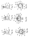
- Figs.1a, 1b and 1c show brakes 10 of the prior art acting on a spindle wharve 11 set in rotation by a belt 12 in the direction of the arrow 13.
- the brakes 10 are applied by the machine operative in the direction of the arrow 14 and work by the pressure of a rigid brake shoe 15 against the spindle wharve 11.
- Resilient deformable elements 16 are employed to graduate the start-up of the spindle and act directly on the spindle wharve 11, or else the pressure of the brake shoe 15 is exerted by means of a spring 17 or other resilient means.
- Figs.2a, 2b and 2c show an embodiment of the invention in the position of normal drawing of a spindle, in the intermediate position and in the position of full disengagement of the belt 12 from the spindle wharve 11 respectively.
- a device 18 which controls the piecing-up of the yarn consists of a distancing element 19, in this example a sleeve, which is fitted at the foot of, and is coaxial with, a spindle 20 and is able to rotate.
- the sleeve 19 comprises an upper body 21 positioned on the outside of the spindle wharve 11.
- This upper body 21 is lacking along a circumferential portion corresponding to an angle of open space "alpha".
- This angle of open space "alpha” is greater than an angle "beta” corresponding to the arc of contact of the belt 12 about the spindle wharve 11 when the sleeve 19 is in the position of normal drawing of the spindle 20 (see Fig.2a).
- the actuation lever 22 bears terminally on its side towards the foot of the spindle 20 a pin 24 cooperating with the outer surface of a second sleeve 25.
- An abutment 26 is machined on the second sleeve 25 and determines the intermediate position of the sleeve 19 coinciding with a limited extent of contact between the belt 12 and spindle wharve 11 (angle "beta 1" smaller than "beta” in Fig.2b).
- Terminal parts 29 of the upper body 21 correspond with the angle of open space "alpha" and are suitably edged to assit introduction of the upper body 21 between the belt 12 and spindle wharve 11.
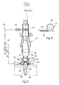
- Fig.3 shows the application of the sleeve 19 to a spinning spindle, which in this example, is a spindle with a rotary balloon checking device 27.
- a device 30 providing a jet of fluid which is advantageously compressed air, is shown with its essential parts in the diagram of Fig.3 and cooperates with the device 18 that controls the piecing-up of the yarn.
- the device 30 providing the jet of fluid consists of a timer 31 to time the duration of the jet and is actuated by a cam 32, comprised in the sleeve 19, during the intermediate position of the sleeve (Fig.2b).
- the timer 31 actuates a solenoid valve 33 connected to the feed of the fluid under pressure 34.
- the fluid under pressure 34 cooperates momentarily through a nozzle 35 with a ring 36 fitted to the upper portion of the rotary balloon checking device 27.
- the ring 36 has a very low weight and an outer surface 37 of a type, knurled for instance, which is suitable to assist the tangential thrust of the fluid.
- the rotary yarn winding means 27 itself comprises an annular portion of knurled surface.
- the device 30 providing a jet of fluid comprises also a pressure regulator with a pressure gauge 38 to regulate the thrust of the compressed air 34 suitably on the rotary balloon checking device 27.
Landscapes
- Engineering & Computer Science (AREA)
- Mechanical Engineering (AREA)
- Textile Engineering (AREA)
- Spinning Or Twisting Of Yarns (AREA)
Description
- This invention concerns a device to control the piecing-up of yarn on spinning machines. To be more exact, the device according to the invention is suitable for spinning and twisting machines having a belt-type drive for the spindles.
- The device can be employed advantageously, but not only, in spinning systems where the rotary yarn-winding means possesses a given weight and therefore a given inertia to angular acceleration, such as is the case, for instance, in some cap spinning systems, in rotary ring spinning systems and in spinning systems employing a rotary balloon checking device.
- Devices are known in the prior art which enable the yarn to be pieced-up after breakage at individual spinning positions.
- Such known devices consist of a brake, ususally a knee brake, by which the machine operative halts the spindle on which he has to work.
- The braking action is applied by pressure on the spindle and lasts for the whole time needed for the piecing-up, in the meanwhile overcoming the drawing force of the drive belt, which slips on the spindle wharve.
- As soon as the operative stops the action of thrusting on the brake, the brake shoe is separated at once from the spindle wharve and the drive belt can apply all its available power to the spindle.
- The spindle accelerates very quickly and reaches its normal running speed in a very short time.
- During this step of strong acceleration there arises in the yarn a tension which depends on the spinning system employed.
- No great problems are involved in the ring spinning system since the yarn has to draw with itself a traveller having a low weight, and therefore the tensions which arise are of a low value.
- In other systems where the yarn has to set a heavier element in rotation, such as certain cap spinning systems or the spinning system with a rotary ring or the spinning system with a rotary balloon checking device, the re-starting of the spindle is problematical and sometimes impossible with the finest yarns.
- The tension created is so great that it very often overcomes the strength of the yarn.
- Improved braking devices have been used which are suitable to graduate the start-up of the spindle when piecing-up takes place.
- All the known devices entail the drawback that the graduation of the acceleration depends on the sensitiveness of the machine operative. As a result the piecing-up operation has a random nature.
- Moreover, during the piecing-up of the yarn the operative is busy all the time with the braking task and with a gradual start-up of the spindle.
- GB-A-193,131 mentions improvements in and relating to stop apparatus for the spindles of spinning and twisting machines.
- A semi-rotary disc is therefore mounted on a fixed spindle, which has on its periphery an upstanding cam-shaped projection.
- When the disc is partly rotated from its normal position, this projection engages the actuating belt to release it from engagement with the pulley wheel of a rotary tube.
- The disc is provided with an integral extension piece or lever to which a wire cord is fastened, which is carried along and connected to one arm of a bell crank.
- The bell crank is vertically disposed to the horizontal disc and is employed by foot pressure on a spring pedal connected to the other arm by a wire cord.
- This kind of stop apparatus is, however, not apt for controlling the piecing up with modern spinning machines, because of the different force deflections by the levers and the wire cords.
- Moreover, the mentioned stop apparatus has only two defined positions, which are defined by the spring pedal.
- Any abutments or stops directly related to the disc are not provided.
- EP-A-0225660 describes a method and system for spinning with a rotary balloon-checking device.
- This checking device or cap can be driven by an independent motor which is moved with a reciprocating vertical motion or be driven by a pulley cooperating with a belt.
- Any control mechanism for controlling piecing-up of yarn as in the present invention is not disclosed.
- US-A-2,833,111 discloses cap spinning frames and cap twisting frames which are driven by an electromotor.
- The upper end of a rotatable vertical spindle is separately driven by another electromotor and projects into the interior of the cap.
- For stopping of the cap, preferably controllable direct current ore reverse current or eddy corrent is supplied.
- As belt-driven spindles are not described, this reference is no further of interest in respect with the present invention.
- The present applicant has designed, tested and embodied a device able to overcome all the shortcomings of the known art.
- The device according to the invention consists of an element to distance the drive belt of the spindle from the spindle wharve.
- The distancing element is fitted in correspondence with the foot of the spindle and is able to rotate about the axis of the spindle.
- This distancing element is worked by the machine operative by hand and has at least three defined working positions:
- a position for the normal drawing of the spindle with full contact between the drive belt and the spindle wharve,
- an intermediate position with a limited extent of contact between the belt and the spindle wharve, and
- a position of complete separation of the belt from the spindle wharve.
- When taking corrective action after a yarn breakage, the operative rotates the distancing element at once from the normal drawing position to the position of complete separation of the belt from the spindle wharve, thus halting the spindle.
- When the spindle has halted, the operative arranges, as in the known art, a segment of yarn of a length suitable for the piecing-up. He then rotates the distancing element to the intermediate position, waits for some moments and then carries out the piecing-up.
- While the piecing-up is being carried out, the spindle gradually reaches its normal running speed and the operative can rotate the distancing element to the position for normal drawing of the spindle without altering the speed of rotation of the spindle. There are therefore no stresses applied to the yarn.
- The device provides for the ability to vary the point of the intermediate position and therefore to vary the arc of contact between the belt and the spindle wharve so as to obtain different degrees of acceleration of the spindle.
- According to a variant a jet of fluid able to contribute to the drawing of the yarn winding means by the yarn may cooperate momentarily with the element that distances the spindle drive belt.
- Such jet of fluid begins working in the neighbourhood of the intermediate position to assist the start-up of the spindle and ends its action when the normal running speed has been reached.
- In this variant there is no need for the drive of the spindle to be synchronized with the drive of the yarn winding means since the thrust of the jet of fluid helps in the acceleration of the yarn winding means irrespective of the type of movement imposed on the yarn winding means by the spindle.
- The invention is therefore embodied according to the contents of Claim 1 and of the dependent claims.
- The attached figures, which are given as a non-restrictive example, show the following:-
- Figs.1a, 1b and 1c
- give diagrammatic plan views of some embodiments of the prior art;
- Fig.2a, 2b and 2c
- give diagrammatic plan views of an embodiment of the device according to the invention;
- Fig.3
- shows a diagrammatic vertical section of the device of Fig.2 as applied to a spinning spindle, together with a variant of the invention.
- Fig.4
- shows a cross section of a detail of the variant of Fig.3.
- Figs.1a, 1b and
1c show brakes 10 of the prior art acting on aspindle wharve 11 set in rotation by abelt 12 in the direction of thearrow 13. - The
brakes 10 are applied by the machine operative in the direction of thearrow 14 and work by the pressure of arigid brake shoe 15 against thespindle wharve 11. - Resilient
deformable elements 16 are employed to graduate the start-up of the spindle and act directly on thespindle wharve 11, or else the pressure of thebrake shoe 15 is exerted by means of aspring 17 or other resilient means. - Figs.2a, 2b and 2c show an embodiment of the invention in the position of normal drawing of a spindle, in the intermediate position and in the position of full disengagement of the
belt 12 from thespindle wharve 11 respectively. - A
device 18 which controls the piecing-up of the yarn consists of adistancing element 19, in this example a sleeve, which is fitted at the foot of, and is coaxial with, aspindle 20 and is able to rotate. - The
sleeve 19 comprises anupper body 21 positioned on the outside of thespindle wharve 11. Thisupper body 21 is lacking along a circumferential portion corresponding to an angle of open space "alpha". This angle of open space "alpha" is greater than an angle "beta" corresponding to the arc of contact of thebelt 12 about thespindle wharve 11 when thesleeve 19 is in the position of normal drawing of the spindle 20 (see Fig.2a). - The
sleeve 19 comprises anactuation lever 22, which is operated by the machine operative and cooperates with abutment stops 23 and 123 that provide respectively the position of normal drawing of the spindle and the position of full disengagement of thebelt 12 from the spindle wharve 11 ("beta" = 0 as in Fig.2c). - The
actuation lever 22 bears terminally on its side towards the foot of the spindle 20 apin 24 cooperating with the outer surface of asecond sleeve 25. - An
abutment 26 is machined on thesecond sleeve 25 and determines the intermediate position of thesleeve 19 coinciding with a limited extent of contact between thebelt 12 and spindle wharve 11 (angle "beta 1" smaller than "beta" in Fig.2b). - The
upper body 21 comprises a surface of arounded type 28 for contact with thebelt 12 so as to keep the belt aligned during disengagement from thespindle wharve 11. -
Terminal parts 29 of theupper body 21 correspond with the angle of open space "alpha" and are suitably edged to assit introduction of theupper body 21 between thebelt 12 and spindle wharve 11. - Fig.3 shows the application of the
sleeve 19 to a spinning spindle, which in this example, is a spindle with a rotaryballoon checking device 27. - According to a variant a
device 30 providing a jet of fluid, which is advantageously compressed air, is shown with its essential parts in the diagram of Fig.3 and cooperates with thedevice 18 that controls the piecing-up of the yarn. - The
device 30 providing the jet of fluid consists of atimer 31 to time the duration of the jet and is actuated by acam 32, comprised in thesleeve 19, during the intermediate position of the sleeve (Fig.2b). - The
timer 31 actuates asolenoid valve 33 connected to the feed of the fluid underpressure 34. - The fluid under
pressure 34 cooperates momentarily through anozzle 35 with aring 36 fitted to the upper portion of the rotaryballoon checking device 27. - The
ring 36 has a very low weight and anouter surface 37 of a type, knurled for instance, which is suitable to assist the tangential thrust of the fluid. - According to a variant the rotary yarn winding means 27 itself comprises an annular portion of knurled surface.
- The
device 30 providing a jet of fluid comprises also a pressure regulator with apressure gauge 38 to regulate the thrust of thecompressed air 34 suitably on the rotaryballoon checking device 27.
Claims (12)
- Device (18) to control the piecing-up of yarn on spinning machines with belt-driven (12) spindles (20), such spinning machines employing advantageously spinning systems with rotary winding means (27) of a relatively heavy type, consisting of an element (19) to distance the spindle drive belt (12) from the spindle (20), the element (19) being located in correspondence with the foot of and externally coaxial with the spindle (20) and being able to rotate freely, characterized in that the distancing element (19) comprising an upper body (21) positioned on and at least partly surrounding the outside of a spindle wharve (11), and an actuation lever (22) which cooperates with abutment stops (23;123) for defining two working positions, namely:- a position for normal drawing of the spindle (Fig. 2a) with the drive belt (12) fully in contact with the spindle wharve (11), and- a position of complete separation (Fig. 2c) of the belt (12) from the spindle wharve (11), and
further comprising an abutment (2b) determining- an intermediate position (Fig. 2b) with a limited extent of contact between the belt (12) and the spindle wharve (11). - Device (18) as claimed in claim 1, in which the upper body (21) of the distancing element (19) being lacking circumferentially along an angular extent ("alpha").
- Device (18) as claimed in claim 2, in which the lacking angular extent ("alpha") is greater than the angular extent ("beta") of contact between the belt (12) and the spindle wharve (11) in the position of normal drawing of the spindle.
- Device (18) as claimed in any claim hereinbefore, in which the actuation lever (22) comprises a terminal pin (24) cooperating with an abutment (26) comprised on a sleeve (25).
- Device (18) as claimed in any claim hereinbefore, in which the outer surface of the upper body (21) is rounded (28).
- Device (18) as claimed in any claim hereinbefore, in which the terminal parts (29) of the upper body (21) have an inclined end.
- Device (18) as claimed in any claim hereinbefore, in which the distancing element (19) cooperates with a means (30) providing a jet of fluid.
- Device (18) as claimed in any claim hereinbefore, in which the means (30) providing a jet of fluid comprises a timer (31), a pressure regulator (38) to regulate the fluid (34), a solenoid valve (33) and a nozzle (35) to eject the fluid (34) under pressure.
- Device (18) as claimed in claim 8, in which the timer (31) cooperates with the distancing element (19) during the intermediate position of the latter.
- Device (18) as claimed in claim 8, in which the nozzle (35) cooperates momentarily with a rotary yarn winding means (27).
- Device (18) as claimed in any claim hereinbefore, in which a ring (36) having a knurled surface (37) is fitted to the rotary yarn winding means (27).
- Device (18) as claimed in any of Claims 1 to 12 inclusive, in which the rotary yarn winding means (27) itself comprises an annular portion of knurled surface.
Applications Claiming Priority (2)
| Application Number | Priority Date | Filing Date | Title |
|---|---|---|---|
| IT8783454A IT1214219B (en) | 1987-09-08 | 1987-09-08 | YARN REFITTING CONTROL DEVICE ON YARN. |
| IT8345487 | 1987-09-08 |
Publications (2)
| Publication Number | Publication Date |
|---|---|
| EP0306691A1 EP0306691A1 (en) | 1989-03-15 |
| EP0306691B1 true EP0306691B1 (en) | 1992-04-15 |
Family
ID=11322135
Family Applications (1)
| Application Number | Title | Priority Date | Filing Date |
|---|---|---|---|
| EP88112207A Expired EP0306691B1 (en) | 1987-09-08 | 1988-07-28 | Device to control the piecing-up of yarn on spinning machines |
Country Status (4)
| Country | Link |
|---|---|
| EP (1) | EP0306691B1 (en) |
| JP (1) | JPH01111026A (en) |
| DE (1) | DE3870108D1 (en) |
| IT (1) | IT1214219B (en) |
Families Citing this family (1)
| Publication number | Priority date | Publication date | Assignee | Title |
|---|---|---|---|---|
| US6182434B1 (en) * | 1996-02-28 | 2001-02-06 | Vyzkumny Ustav Bavlnarsky A.S. | Spindle spinning or spindle twisting method and operating unit for carrying out this method |
Family Cites Families (4)
| Publication number | Priority date | Publication date | Assignee | Title |
|---|---|---|---|---|
| GB193131A (en) * | 1921-11-15 | 1923-02-15 | William Christopher Mcloughlin | Improvements in and relating to stop-apparatus for the spindles of spinning and twisting machines |
| US2833111A (en) * | 1955-10-20 | 1958-05-06 | Spinnerei Karl Marx Veb | Cap spinning frames and cap twisting frames |
| IT1218462B (en) * | 1985-12-10 | 1990-04-19 | Cerimates Spa | ROTATING BALLOON LIMITER SPINNING PROCESS AND SYSTEM |
| DE3606609A1 (en) * | 1986-02-28 | 1987-09-03 | Zinser Textilmaschinen Gmbh | LUNTENSTOPP DEVICE ON THE STRETCHER OF A SPINNING MACHINE |
-
1987
- 1987-09-08 IT IT8783454A patent/IT1214219B/en active
-
1988
- 1988-07-28 DE DE8888112207T patent/DE3870108D1/en not_active Expired - Lifetime
- 1988-07-28 EP EP88112207A patent/EP0306691B1/en not_active Expired
- 1988-09-08 JP JP63225510A patent/JPH01111026A/en active Pending
Also Published As
| Publication number | Publication date |
|---|---|
| IT8783454A0 (en) | 1987-09-08 |
| EP0306691A1 (en) | 1989-03-15 |
| IT1214219B (en) | 1990-01-10 |
| DE3870108D1 (en) | 1992-05-21 |
| JPH01111026A (en) | 1989-04-27 |
Similar Documents
| Publication | Publication Date | Title |
|---|---|---|
| US5029762A (en) | Yarn winding apparatus and method | |
| US3841574A (en) | Winding device for synthetic threads | |
| US4080775A (en) | Yarn piecing process and apparatus for an open end spinning assembly | |
| US4004438A (en) | Thread feed device for a hosiery knitting machine | |
| US3805504A (en) | Apparatus for pneumatically stopping spindle assemblies of a textile yarn processing machine in a predetermined position | |
| US4281508A (en) | Yarn brake mechanism | |
| US4389837A (en) | Ply yarn spinning assembly | |
| US3002333A (en) | Improved yarn breakage detection means for textile twisting machines | |
| EP0306691A1 (en) | Device to control the piecing-up of yarn on spinning machines | |
| RU2215072C2 (en) | Method and apparatus for starting of rewinding process during centrifugal spinning after thread breakage | |
| US2785526A (en) | Twister spindle | |
| US5079908A (en) | Arrangement for carrying out a yarn piecing operation at a spinning point of a spinning machine | |
| US3521826A (en) | Yarn package transfer apparatus | |
| US20020033012A1 (en) | Method and apparatus for the simultaneous centralized control of the yarn brakes of twist spindles of a two-for-one twisting machine | |
| US4495758A (en) | Apparatus and method for forming a wrapped yarn | |
| US20040025656A1 (en) | Assembly and method for cutting strands formed by thermoplastic filaments | |
| US3003303A (en) | Textile twisting machine control mechanism | |
| EP0284846B1 (en) | Method to wind down a yarn package and device to perform the method | |
| US724975A (en) | Thread-unroller. | |
| US2650414A (en) | Control device | |
| US4606186A (en) | Auxiliary roller drive for open-end friction spinning machine | |
| US3438187A (en) | Method of automatically threading yarn from a bobbin into the ring traveller of a continuous ring spinning machine and the like | |
| US3398522A (en) | Textile machine | |
| US3098346A (en) | Spindle drive arrangement for a spinning or twisting frame | |
| US4531557A (en) | Weft reservoir for fluid jet looms |
Legal Events
| Date | Code | Title | Description |
|---|---|---|---|
| PUAI | Public reference made under article 153(3) epc to a published international application that has entered the european phase |
Free format text: ORIGINAL CODE: 0009012 |
|
| AK | Designated contracting states |
Kind code of ref document: A1 Designated state(s): CH DE GB LI |
|
| 17P | Request for examination filed |
Effective date: 19890724 |
|
| RAP1 | Party data changed (applicant data changed or rights of an application transferred) |
Owner name: MASCHINENFABRIK RIETER AG |
|
| 17Q | First examination report despatched |
Effective date: 19901221 |
|
| GRAA | (expected) grant |
Free format text: ORIGINAL CODE: 0009210 |
|
| AK | Designated contracting states |
Kind code of ref document: B1 Designated state(s): CH DE GB LI |
|
| PG25 | Lapsed in a contracting state [announced via postgrant information from national office to epo] |
Ref country code: LI Effective date: 19920415 Ref country code: CH Effective date: 19920415 |
|
| REF | Corresponds to: |
Ref document number: 3870108 Country of ref document: DE Date of ref document: 19920521 |
|
| PG25 | Lapsed in a contracting state [announced via postgrant information from national office to epo] |
Ref country code: GB Effective date: 19920728 |
|
| REG | Reference to a national code |
Ref country code: CH Ref legal event code: PL |
|
| PLBE | No opposition filed within time limit |
Free format text: ORIGINAL CODE: 0009261 |
|
| GBPC | Gb: european patent ceased through non-payment of renewal fee |
Effective date: 19920728 |
|
| PG25 | Lapsed in a contracting state [announced via postgrant information from national office to epo] |
Ref country code: DE Effective date: 19930401 |
|
| 26N | No opposition filed |