EP0306146A1 - Battery vent valve - Google Patents
Battery vent valve Download PDFInfo
- Publication number
- EP0306146A1 EP0306146A1 EP88307078A EP88307078A EP0306146A1 EP 0306146 A1 EP0306146 A1 EP 0306146A1 EP 88307078 A EP88307078 A EP 88307078A EP 88307078 A EP88307078 A EP 88307078A EP 0306146 A1 EP0306146 A1 EP 0306146A1
- Authority
- EP
- European Patent Office
- Prior art keywords
- battery
- skirt
- pressure
- valve
- chamber
- Prior art date
- Legal status (The legal status is an assumption and is not a legal conclusion. Google has not performed a legal analysis and makes no representation as to the accuracy of the status listed.)
- Granted
Links
- 238000007789 sealing Methods 0.000 claims abstract description 41
- 230000007423 decrease Effects 0.000 claims description 3
- 230000002159 abnormal effect Effects 0.000 claims description 2
- 238000013022 venting Methods 0.000 abstract description 8
- 239000007789 gas Substances 0.000 description 38
- 230000006798 recombination Effects 0.000 description 6
- 238000005215 recombination Methods 0.000 description 6
- QVGXLLKOCUKJST-UHFFFAOYSA-N atomic oxygen Chemical compound [O] QVGXLLKOCUKJST-UHFFFAOYSA-N 0.000 description 5
- 239000001301 oxygen Substances 0.000 description 4
- 229910052760 oxygen Inorganic materials 0.000 description 4
- 229920002633 Kraton (polymer) Polymers 0.000 description 2
- 239000002253 acid Substances 0.000 description 2
- 239000000463 material Substances 0.000 description 2
- 239000008188 pellet Substances 0.000 description 2
- 239000002174 Styrene-butadiene Substances 0.000 description 1
- MTAZNLWOLGHBHU-UHFFFAOYSA-N butadiene-styrene rubber Chemical compound C=CC=C.C=CC1=CC=CC=C1 MTAZNLWOLGHBHU-UHFFFAOYSA-N 0.000 description 1
- 238000007599 discharging Methods 0.000 description 1
- 229920001971 elastomer Polymers 0.000 description 1
- 239000000806 elastomer Substances 0.000 description 1
- 239000003792 electrolyte Substances 0.000 description 1
- 239000001257 hydrogen Substances 0.000 description 1
- 229910052739 hydrogen Inorganic materials 0.000 description 1
- 125000004435 hydrogen atom Chemical class [H]* 0.000 description 1
- 230000004941 influx Effects 0.000 description 1
- 239000000203 mixture Substances 0.000 description 1
- QELJHCBNGDEXLD-UHFFFAOYSA-N nickel zinc Chemical compound [Ni].[Zn] QELJHCBNGDEXLD-UHFFFAOYSA-N 0.000 description 1
- 230000002035 prolonged effect Effects 0.000 description 1
- 239000011115 styrene butadiene Substances 0.000 description 1
- 229920003048 styrene butadiene rubber Polymers 0.000 description 1
Images

Classifications
-
- H—ELECTRICITY
- H01—ELECTRIC ELEMENTS
- H01M—PROCESSES OR MEANS, e.g. BATTERIES, FOR THE DIRECT CONVERSION OF CHEMICAL ENERGY INTO ELECTRICAL ENERGY
- H01M50/00—Constructional details or processes of manufacture of the non-active parts of electrochemical cells other than fuel cells, e.g. hybrid cells
- H01M50/30—Arrangements for facilitating escape of gases
- H01M50/383—Flame arresting or ignition-preventing means
-
- H—ELECTRICITY
- H01—ELECTRIC ELEMENTS
- H01M—PROCESSES OR MEANS, e.g. BATTERIES, FOR THE DIRECT CONVERSION OF CHEMICAL ENERGY INTO ELECTRICAL ENERGY
- H01M50/00—Constructional details or processes of manufacture of the non-active parts of electrochemical cells other than fuel cells, e.g. hybrid cells
- H01M50/30—Arrangements for facilitating escape of gases
- H01M50/317—Re-sealable arrangements
- H01M50/325—Re-sealable arrangements comprising deformable valve members, e.g. elastic or flexible valve members
-
- F—MECHANICAL ENGINEERING; LIGHTING; HEATING; WEAPONS; BLASTING
- F16—ENGINEERING ELEMENTS AND UNITS; GENERAL MEASURES FOR PRODUCING AND MAINTAINING EFFECTIVE FUNCTIONING OF MACHINES OR INSTALLATIONS; THERMAL INSULATION IN GENERAL
- F16K—VALVES; TAPS; COCKS; ACTUATING-FLOATS; DEVICES FOR VENTING OR AERATING
- F16K15/00—Check valves
- F16K15/14—Check valves with flexible valve members
- F16K15/144—Check valves with flexible valve members the closure elements being fixed along all or a part of their periphery
-
- F—MECHANICAL ENGINEERING; LIGHTING; HEATING; WEAPONS; BLASTING
- F16—ENGINEERING ELEMENTS AND UNITS; GENERAL MEASURES FOR PRODUCING AND MAINTAINING EFFECTIVE FUNCTIONING OF MACHINES OR INSTALLATIONS; THERMAL INSULATION IN GENERAL
- F16K—VALVES; TAPS; COCKS; ACTUATING-FLOATS; DEVICES FOR VENTING OR AERATING
- F16K15/00—Check valves
- F16K15/14—Check valves with flexible valve members
- F16K15/144—Check valves with flexible valve members the closure elements being fixed along all or a part of their periphery
- F16K15/145—Check valves with flexible valve members the closure elements being fixed along all or a part of their periphery the closure elements being shaped as a solids of revolution, e.g. cylindrical or conical
-
- H—ELECTRICITY
- H01—ELECTRIC ELEMENTS
- H01M—PROCESSES OR MEANS, e.g. BATTERIES, FOR THE DIRECT CONVERSION OF CHEMICAL ENERGY INTO ELECTRICAL ENERGY
- H01M50/00—Constructional details or processes of manufacture of the non-active parts of electrochemical cells other than fuel cells, e.g. hybrid cells
- H01M50/30—Arrangements for facilitating escape of gases
- H01M50/394—Gas-pervious parts or elements
-
- Y—GENERAL TAGGING OF NEW TECHNOLOGICAL DEVELOPMENTS; GENERAL TAGGING OF CROSS-SECTIONAL TECHNOLOGIES SPANNING OVER SEVERAL SECTIONS OF THE IPC; TECHNICAL SUBJECTS COVERED BY FORMER USPC CROSS-REFERENCE ART COLLECTIONS [XRACs] AND DIGESTS
- Y02—TECHNOLOGIES OR APPLICATIONS FOR MITIGATION OR ADAPTATION AGAINST CLIMATE CHANGE
- Y02E—REDUCTION OF GREENHOUSE GAS [GHG] EMISSIONS, RELATED TO ENERGY GENERATION, TRANSMISSION OR DISTRIBUTION
- Y02E60/00—Enabling technologies; Technologies with a potential or indirect contribution to GHG emissions mitigation
- Y02E60/10—Energy storage using batteries
-
- Y—GENERAL TAGGING OF NEW TECHNOLOGICAL DEVELOPMENTS; GENERAL TAGGING OF CROSS-SECTIONAL TECHNOLOGIES SPANNING OVER SEVERAL SECTIONS OF THE IPC; TECHNICAL SUBJECTS COVERED BY FORMER USPC CROSS-REFERENCE ART COLLECTIONS [XRACs] AND DIGESTS
- Y10—TECHNICAL SUBJECTS COVERED BY FORMER USPC
- Y10T—TECHNICAL SUBJECTS COVERED BY FORMER US CLASSIFICATION
- Y10T137/00—Fluid handling
- Y10T137/7722—Line condition change responsive valves
- Y10T137/7837—Direct response valves [i.e., check valve type]
- Y10T137/7879—Resilient material valve
-
- Y—GENERAL TAGGING OF NEW TECHNOLOGICAL DEVELOPMENTS; GENERAL TAGGING OF CROSS-SECTIONAL TECHNOLOGIES SPANNING OVER SEVERAL SECTIONS OF THE IPC; TECHNICAL SUBJECTS COVERED BY FORMER USPC CROSS-REFERENCE ART COLLECTIONS [XRACs] AND DIGESTS
- Y10—TECHNICAL SUBJECTS COVERED BY FORMER USPC
- Y10T—TECHNICAL SUBJECTS COVERED BY FORMER US CLASSIFICATION
- Y10T137/00—Fluid handling
- Y10T137/7722—Line condition change responsive valves
- Y10T137/7837—Direct response valves [i.e., check valve type]
- Y10T137/7879—Resilient material valve
- Y10T137/7888—With valve member flexing about securement
- Y10T137/7889—Sleeve
Definitions
- This invention relates to valves for venting electric storage batteries as specified in the preamble of claim 1, for example as disclosed in US-A-4 576 879.
- Sealed batteries are well known in the art and typically include a relief/check valve for venting gases generated within the battery when the internal gas pressure exceeds a predetermined superatmospheric level.
- Nickel-zinc batteries for example, commonly operate with a positive internal gas pressure of about 3.45 kPa (one half pound per square inch) or more to promote oxygen recombination within the battery and to keep CO2 in the air from contaminating the electrolyte when the pressure in the cell falls below atmospheric pressure (zero psig).
- gas recombination type lead-acid batteries are known to operate at internal gas pressures ranging from about 3.45 kPa to about 345 kPa (1/2 psig to about 50 psig) (i.e., depending on the particular application) to promote the oxygen recombination reaction and to exclude ambient oxygen from the battery. It is necessary for the prolonged life of such batteries that, after the gases have been vented, the relief/check valves close and reseal as near as possible to their opening pressure in order (1) to prevent unnecessary loss of the internal gases otherwise available for recombination and (2) to prevent any influx of ambient atmosphere into the battery as the internal gas pressure within the battery falls.
- batteries Under uncontrolled recharge, batteries can generate so much gas that the internal pressure can rapidly exceed the design pressure of the container unless the check valves are capable of quickly dumping or venting relatively large volumes (i.e., litres per minute) of the gases at relatively low internal gas pressures.
- relatively large volumes i.e., litres per minute
- some lead-acid batteries can generate more than 10 times the amount of gas otherwise generated under normal charging conditions.
- valves commonly used in batteries do not actually reseal again until pressures as low as 25% or less of their opening pressure are reached. In fact, some such valves tested by General Motors Corporation did not reseal until the pressure in the battery had dropped below atmospheric pressure (zero psig). Moreover, valves designed for rapid resealing at relatively high pressures do not usually have a capability for low pressure dumping of large volumes of gas, and vice versa. No commercially available battery check valve has been found which provides both rapid, effective resealing near the opening pressure thereof as well as a high gas volume venting capability at relatively low internal gas pressures. In this latter regard, all of the commercial valves tested produced pressure build-ups which were significantly more than twice the opening pressure of the valve in order to dump high volumes of gas.
- a battery vent valve in an electric storage battery according to the present invention is characterised by the features specified in the characterising portion of claim 1.
- the present invention comprises a check/relief valve for an electric storage battery which is capable of resealing at pressures of at least 50% or more of its opening pressure and of releasing relatively large volumes of internal gases without excessive gas pressure build-up within the battery.
- the valve of the present invention comprises a housing defining a vent chamber having a gas inlet for receiving gases from within the battery and an outlet for discharging them to the atmosphere.
- the housing includes a valve seat projecting into the chamber and having a sloping (preferably conical) exterior sealing surface.
- a sealing member circumscribes the inlet and includes an annular elastomeric skirt having a sealing edge circumferentially sealingly engaging the sealing surface of the seat.
- the elasticity of the skirt is selected based on the desired relief pressure sought for the battery under normal operating conditions and is such that the skirt will begin to flare radially outwardly when the desired pressure is reached so as to form an annular gap between the sealing edge of the skirt and the sealing surface of the seat through which the gases flow.
- Elasticity of the skirt, and hence the opening pressure of the valve may be varied over a wide range by varying the dimensions of the skirt and the hardness (i.e., durometer hardness) of the elastomer used.
- the gases generated inside the battery act against the relatively large surface area on the inside of the skirt so as to cause outward flaring of the skirt at relatively low pressures.
- the skirt Under conditions where excessive gases are formed (e.g., run-away charging), the skirt will simply flare out further so as to increase the gap (i.e., the area of the flow path), between the skirt and the seat.
- the gap i.e., the area of the flow path
- the area of the gap through which the gas flows increases exponentially (i.e., by the square of the radius - R2) so that much larger volumes of gas than normal can be vented without a significant increase in internal pressure.
- Vents made in accordance with the present invention have demonstrated the capability of dumping more than 10 times the normal volume of gases generated with a pressure build-up of less than twice the opening pressure of the valve.
- the opening pressure of the relief/check valve is adjustable by providing means for moving the sealing member to and fro with respect to the seat such that the skirt of the sealing member engages the sloping surface of the valve seat at different locations so as to pre-stress the skirt to various degrees and thereby vary the amount of pressure required to flare the skirt outwardly away from the seat.
- FIG. 1 shows a battery 2 having a container 4 divided into a plurality of individual cell compartments 6.
- Each compartment contains, as shown in Figure 2, a cell element 8 comprising a plurality of alternately interleaved positive and negative polarity plates for electrochemically generating electrical current upon discharge of the battery and which generate gases (e.g., hydrogen (H2) and oxygen (O2) on recharge, which gases are recombined within the cell as is well-known in the gas recombination battery art.
- gases e.g., hydrogen (H2) and oxygen (O2) on recharge, which gases are recombined within the cell as is well-known in the gas recombination battery art.
- a vent 10 is provided in a cover 12 of the container 4, which vent 10 includes a check/relief valve 14 which is described in more detail hereinafter.
- the relief valve 14 includes a housing 16 defining a venting chamber 18 and having a valve seat 20 at its lower end.
- the housing 16 may be integral with the cover 12 as shown in the drawings or may be discrete for positioning in an aperture in the cover (not shown).
- the valve seat 20 has a sloping (preferably conical) external sealing surface 22 for engagement by an annular skirt 24 on the depending elastomeric tubular sealing member 26.
- the elastomeric tube 26 will comprise a rubber-like material such as a styrene-butadiene material, sold under the trade name Kraton (RTM) by Shell Oil Company, U.S.A..
- the tubular sealing member 26 is secured to a bulbous stud 28 depending from a plug 30 which serves to close off the vent chamber 18 from the ambient atmosphere surrounding the battery. Exhaust ports 32 in the plug 30 allow gases to escape from the vent chamber 18 to the ambient atmosphere.
- An inlet opening 34 passing through the centre of the seat 20 serves to communicate the vent chamber 18 with the battery cell compartment 6.
- the plug 30 is threaded into the housing 16 so as to permit adjustment of the opening and closing pressure of the tubular valve member 26 by advancing the member 26 to and fro with respect to the seat 20 such that the skirt 24 can locate at different sites along the sloping surface 22 of the seat 20 so as to diametrically pre-stress the skirt 24 to different degrees and thereby change its opening and closing (i.e., flaring) characteristics.
- the ability to adjust the opening pressure of the valve is particularly useful during the design phase of a battery as a means to readily adjust the pressure in the cell to optimize the recombination reaction.
- the adjustability feature is likewise advantageous during the commercial development phase of the battery as a means to provide a standardized vent assembly which may simply be set to different opening pressures as may be required for different battery models and/or applications.
- a tubular sealing member 40 includes a central elastomeric web portion 42 proximate a skirt 44 which serves to ensure that the gas vents at the skirt 44 rather than leaking out around a mounting stud 46.
- the domed shape and location of the web 42 relative to the skirt 44 permits precise tailoring of the opening and closing pressures of the valve member.
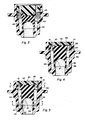
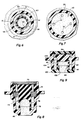
- FIGs 4-7 depict another embodiment of the present invention wherein a sealing member 50 is integrally moulded with a plug portion 52 and includes a hemispherical cavity 54 above a sealing edge 56 of a skirt 58.
- the plug 52 is seated on a shoulder 53 on the inside of a housing 55 and is held in place by a porous flame-arrestor pellet 57 suitably secured in place as is well-known in the art.
- An annular space 59 between the pellet 57 and the plug 52 forms a plenum for the gases exiting the exhaust ports 51 to spread out for more uniform passage through the flame arrestor 57.
- the hemispherically domed cavity 54 in the sealing member 50 provides a skirt 58 which is thicker near its top 61 than at the sealing edge 56 (i.e., its thickness decreases in the direction of the sealing edge) which serves to focus the opening action substantially at the sealing edge 56 (see Figure 5) and helps prevent bulging, rather than flaring, of the skirt 58.
- a similar result is obtained by providing a skirt whose thickness tapers toward the sealing edge as would result, for example, by replacing the hemispherically domed cavity 54 with a frusto-conically shaped cavity.
- Figure 5 depicts opening/flaring of the skirt 58 under normal gassing conditions in solid lines and opening/flaring of the skirt 58 under high gassing conditions in phantom lines.
- the opening/flaring of the skirt 58 provides an annular gap 63 between the skirt 58 and seat 65 through which the gases flow.
- Figure 8 depicts an embodiment of the present invention wherein a plug 70 is integral with a sealing member 72 and is adapted to be screwed into a housing 74 to provide the adjustable feature discussed above. As shown, a sealing edge 76 of a skirt 78 is further down on a seat 80 so as to pre-stress the skirt and thereby increase the pressure at which the skirt will flare outwardly.
- Figure 9 depicts still another embodiment of the present invention wherein a housing 90 defines a vent chamber 92 having a valve seat 94 at the exhaust end thereof and a sealing member 96 secured to a hollow cylindrical stud 98 on an end piece 100 at the inlet side of the chamber 92.
- An opening 102 through the stud 98 serves as the inlet for the gases to the venting chamber 92 from the cell compartment.
- a sealing edge 95 on a skirt 104 of the sealing member 96 engages the seat 94 in close proximity to exhaust ports 106 as shown.
- the tubular elastomeric sealing member 96 may conveniently be glued or otherwise permanently secured to the cylindrical stud 98 so as to ensure that all the valving action occurs at the seat 94.
- a valve substantially as shown in Figure 3 and adapted to open at about 18.96 kPa (2.75 psig) and close at about 15.51 kPa (2.25 psig) was made from a valve member comprising a 50-50 mixture of 45 durometer and 28 durometer Kraton (RTM) and having an outside diameter of 9.65 mm (0.38 inches), an inside diameter of 7.11 mm (0.28 inches) and a skirt length of 2.54 mm (0.1 inches) (i.e., as measured from the centre of curvature of the hemispherical portion).
- the sealing member engaged a conical seat whose walls sloped downwardly at an angle of 30 degrees from the vertical axis. Valves so made are capable of dumping up to 14 litres/minute of gas at internal gas pressures of 34.47 kPa (5 psig) or less.
Landscapes
- Chemical & Material Sciences (AREA)
- Chemical Kinetics & Catalysis (AREA)
- Electrochemistry (AREA)
- General Chemical & Material Sciences (AREA)
- Engineering & Computer Science (AREA)
- General Engineering & Computer Science (AREA)
- Mechanical Engineering (AREA)
- Gas Exhaust Devices For Batteries (AREA)
Abstract
Description
- This invention relates to valves for venting electric storage batteries as specified in the preamble of claim 1, for example as disclosed in US-A-4 576 879.
- Sealed batteries are well known in the art and typically include a relief/check valve for venting gases generated within the battery when the internal gas pressure exceeds a predetermined superatmospheric level. Nickel-zinc batteries, for example, commonly operate with a positive internal gas pressure of about 3.45 kPa (one half pound per square inch) or more to promote oxygen recombination within the battery and to keep CO₂ in the air from contaminating the electrolyte when the pressure in the cell falls below atmospheric pressure (zero psig). Similarly gas recombination type lead-acid batteries are known to operate at internal gas pressures ranging from about 3.45 kPa to about 345 kPa (1/2 psig to about 50 psig) (i.e., depending on the particular application) to promote the oxygen recombination reaction and to exclude ambient oxygen from the battery. It is necessary for the prolonged life of such batteries that, after the gases have been vented, the relief/check valves close and reseal as near as possible to their opening pressure in order (1) to prevent unnecessary loss of the internal gases otherwise available for recombination and (2) to prevent any influx of ambient atmosphere into the battery as the internal gas pressure within the battery falls.
- Under uncontrolled recharge, batteries can generate so much gas that the internal pressure can rapidly exceed the design pressure of the container unless the check valves are capable of quickly dumping or venting relatively large volumes (i.e., litres per minute) of the gases at relatively low internal gas pressures. For example, under high rate charge conditions such as can occur with a full field charge from an unregulated automobile generator/alternator or with other faulty charging equipment, some lead-acid batteries can generate more than 10 times the amount of gas otherwise generated under normal charging conditions.
- Some valves commonly used in batteries do not actually reseal again until pressures as low as 25% or less of their opening pressure are reached. In fact, some such valves tested by General Motors Corporation did not reseal until the pressure in the battery had dropped below atmospheric pressure (zero psig). Moreover, valves designed for rapid resealing at relatively high pressures do not usually have a capability for low pressure dumping of large volumes of gas, and vice versa. No commercially available battery check valve has been found which provides both rapid, effective resealing near the opening pressure thereof as well as a high gas volume venting capability at relatively low internal gas pressures. In this latter regard, all of the commercial valves tested produced pressure build-ups which were significantly more than twice the opening pressure of the valve in order to dump high volumes of gas.
- Accordingly, it is an object of the present invention to provide a unique, compact, relief/check valve for venting an electric storage battery which valve is capable of resealing at pressures of at least 50% or more of its opening pressure and of dumping relatively large volumes of gases under abnormal operating conditions without excessive build up of gas pressure within the battery container. This and other objects and advantages of the present invention will become more readily apparent from the detailed description thereof which follows.
- A battery vent valve in an electric storage battery according to the present invention is characterised by the features specified in the characterising portion of claim 1.
- The present invention comprises a check/relief valve for an electric storage battery which is capable of resealing at pressures of at least 50% or more of its opening pressure and of releasing relatively large volumes of internal gases without excessive gas pressure build-up within the battery. The valve of the present invention comprises a housing defining a vent chamber having a gas inlet for receiving gases from within the battery and an outlet for discharging them to the atmosphere. The housing includes a valve seat projecting into the chamber and having a sloping (preferably conical) exterior sealing surface. A sealing member circumscribes the inlet and includes an annular elastomeric skirt having a sealing edge circumferentially sealingly engaging the sealing surface of the seat. The elasticity of the skirt is selected based on the desired relief pressure sought for the battery under normal operating conditions and is such that the skirt will begin to flare radially outwardly when the desired pressure is reached so as to form an annular gap between the sealing edge of the skirt and the sealing surface of the seat through which the gases flow. Elasticity of the skirt, and hence the opening pressure of the valve, may be varied over a wide range by varying the dimensions of the skirt and the hardness (i.e., durometer hardness) of the elastomer used.
- The gases generated inside the battery act against the relatively large surface area on the inside of the skirt so as to cause outward flaring of the skirt at relatively low pressures. Under conditions where excessive gases are formed (e.g., run-away charging), the skirt will simply flare out further so as to increase the gap (i.e., the area of the flow path), between the skirt and the seat. Hence with only a slight increase in the diameter of the flared out skirt, the area of the gap through which the gas flows increases exponentially (i.e., by the square of the radius - R²) so that much larger volumes of gas than normal can be vented without a significant increase in internal pressure. Vents made in accordance with the present invention have demonstrated the capability of dumping more than 10 times the normal volume of gases generated with a pressure build-up of less than twice the opening pressure of the valve.
- According to a preferred embodiment of the present invention, the opening pressure of the relief/check valve is adjustable by providing means for moving the sealing member to and fro with respect to the seat such that the skirt of the sealing member engages the sloping surface of the valve seat at different locations so as to pre-stress the skirt to various degrees and thereby vary the amount of pressure required to flare the skirt outwardly away from the seat.
- The invention may better be understood when considered in conjunction with the following detailed description of certain specific embodiments thereof which is given hereafter in conjunction with the accompanying drawings, in which:
- Figure 1 is a side elevational view of an electric storage battery having vent valves in accordance with the present invention;
- Figure 2 is an enlarged section of a check/relief valve taken in the direction 2-2 of Figure 1;
- Figure 3 is a view similar to Figure 2 of another embodiment of a relief valve in accordance with the present invention;
- Figure 4 is a view similar to Figure 2 of still another embodiment of a relief valve in accordance with the present invention showing a valve member in the seated, closed condition;
- Figure 5 is essentially the same as Figure 4 except that the valve member shown in the unseated open condition(s);
- Figure 6 is a view in the direction 6-6 of Figure 5;
- Figure 7 is a view in the direction 7-7 of Figure 5;
- Figure 8 is a view similar to Figure 2 of still another embodiment of the present invention and showing a skirt of a valve member seated more deeply on a valve seat; and
- Figure 9 is a view like that of Figure 2 but of still another embodiment of the present invention.
- Figure 1 shows a
battery 2 having acontainer 4 divided into a plurality of individual cell compartments 6. Each compartment contains, as shown in Figure 2, acell element 8 comprising a plurality of alternately interleaved positive and negative polarity plates for electrochemically generating electrical current upon discharge of the battery and which generate gases (e.g., hydrogen (H₂) and oxygen (O₂) on recharge, which gases are recombined within the cell as is well-known in the gas recombination battery art. Avent 10 is provided in acover 12 of thecontainer 4, which vent 10 includes a check/relief valve 14 which is described in more detail hereinafter. - The
relief valve 14 includes ahousing 16 defining a ventingchamber 18 and having avalve seat 20 at its lower end. Thehousing 16 may be integral with thecover 12 as shown in the drawings or may be discrete for positioning in an aperture in the cover (not shown). Thevalve seat 20 has a sloping (preferably conical)external sealing surface 22 for engagement by anannular skirt 24 on the depending elastomerictubular sealing member 26. Theelastomeric tube 26 will comprise a rubber-like material such as a styrene-butadiene material, sold under the trade name Kraton (RTM) by Shell Oil Company, U.S.A.. Thetubular sealing member 26 is secured to abulbous stud 28 depending from aplug 30 which serves to close off thevent chamber 18 from the ambient atmosphere surrounding the battery.Exhaust ports 32 in theplug 30 allow gases to escape from thevent chamber 18 to the ambient atmosphere. - An inlet opening 34 passing through the centre of the
seat 20 serves to communicate thevent chamber 18 with thebattery cell compartment 6. In the particular embodiment shown in Figure 2, theplug 30 is threaded into thehousing 16 so as to permit adjustment of the opening and closing pressure of thetubular valve member 26 by advancing themember 26 to and fro with respect to theseat 20 such that theskirt 24 can locate at different sites along the slopingsurface 22 of theseat 20 so as to diametrically pre-stress theskirt 24 to different degrees and thereby change its opening and closing (i.e., flaring) characteristics. The ability to adjust the opening pressure of the valve is particularly useful during the design phase of a battery as a means to readily adjust the pressure in the cell to optimize the recombination reaction. The adjustability feature is likewise advantageous during the commercial development phase of the battery as a means to provide a standardized vent assembly which may simply be set to different opening pressures as may be required for different battery models and/or applications. - The embodiment shown in Figure 3 is similar to that of Figure 2 except that a
tubular sealing member 40 includes a centralelastomeric web portion 42 proximate askirt 44 which serves to ensure that the gas vents at theskirt 44 rather than leaking out around a mountingstud 46. Moreover, the domed shape and location of theweb 42 relative to theskirt 44 permits precise tailoring of the opening and closing pressures of the valve member. - Figures 4-7 depict another embodiment of the present invention wherein a sealing
member 50 is integrally moulded with aplug portion 52 and includes ahemispherical cavity 54 above a sealingedge 56 of askirt 58. Theplug 52 is seated on ashoulder 53 on the inside of ahousing 55 and is held in place by a porous flame-arrestor pellet 57 suitably secured in place as is well-known in the art. Anannular space 59 between thepellet 57 and theplug 52 forms a plenum for the gases exiting theexhaust ports 51 to spread out for more uniform passage through theflame arrestor 57. The hemisphericallydomed cavity 54 in the sealingmember 50 provides askirt 58 which is thicker near its top 61 than at the sealing edge 56 (i.e., its thickness decreases in the direction of the sealing edge) which serves to focus the opening action substantially at the sealing edge 56 (see Figure 5) and helps prevent bulging, rather than flaring, of theskirt 58. A similar result is obtained by providing a skirt whose thickness tapers toward the sealing edge as would result, for example, by replacing the hemisphericallydomed cavity 54 with a frusto-conically shaped cavity. Figure 5 depicts opening/flaring of theskirt 58 under normal gassing conditions in solid lines and opening/flaring of theskirt 58 under high gassing conditions in phantom lines. The opening/flaring of theskirt 58 provides anannular gap 63 between theskirt 58 andseat 65 through which the gases flow. - Figure 8 depicts an embodiment of the present invention wherein a
plug 70 is integral with a sealingmember 72 and is adapted to be screwed into ahousing 74 to provide the adjustable feature discussed above. As shown, a sealingedge 76 of askirt 78 is further down on aseat 80 so as to pre-stress the skirt and thereby increase the pressure at which the skirt will flare outwardly. - Figure 9 depicts still another embodiment of the present invention wherein a
housing 90 defines avent chamber 92 having avalve seat 94 at the exhaust end thereof and a sealingmember 96 secured to a hollowcylindrical stud 98 on anend piece 100 at the inlet side of thechamber 92. Anopening 102 through thestud 98 serves as the inlet for the gases to theventing chamber 92 from the cell compartment. A sealingedge 95 on askirt 104 of the sealingmember 96 engages theseat 94 in close proximity to exhaustports 106 as shown. The tubularelastomeric sealing member 96 may conveniently be glued or otherwise permanently secured to thecylindrical stud 98 so as to ensure that all the valving action occurs at theseat 94. - In accordance with one specific example of the present invention, a valve substantially as shown in Figure 3 and adapted to open at about 18.96 kPa (2.75 psig) and close at about 15.51 kPa (2.25 psig) was made from a valve member comprising a 50-50 mixture of 45 durometer and 28 durometer Kraton (RTM) and having an outside diameter of 9.65 mm (0.38 inches), an inside diameter of 7.11 mm (0.28 inches) and a skirt length of 2.54 mm (0.1 inches) (i.e., as measured from the centre of curvature of the hemispherical portion). The sealing member engaged a conical seat whose walls sloped downwardly at an angle of 30 degrees from the vertical axis. Valves so made are capable of dumping up to 14 litres/minute of gas at internal gas pressures of 34.47 kPa (5 psig) or less.
Claims (6)
Applications Claiming Priority (2)
| Application Number | Priority Date | Filing Date | Title |
|---|---|---|---|
| US07/092,131 US4780378A (en) | 1987-09-02 | 1987-09-02 | Battery vent valve |
| US92131 | 1998-06-05 |
Publications (2)
| Publication Number | Publication Date |
|---|---|
| EP0306146A1 true EP0306146A1 (en) | 1989-03-08 |
| EP0306146B1 EP0306146B1 (en) | 1993-01-13 |
Family
ID=22231775
Family Applications (1)
| Application Number | Title | Priority Date | Filing Date |
|---|---|---|---|
| EP88307078A Expired - Lifetime EP0306146B1 (en) | 1987-09-02 | 1988-08-01 | Battery vent valve |
Country Status (7)
| Country | Link |
|---|---|
| US (1) | US4780378A (en) |
| EP (1) | EP0306146B1 (en) |
| JP (1) | JPH0758612B2 (en) |
| KR (1) | KR920003756B1 (en) |
| BR (1) | BR8804337A (en) |
| CA (1) | CA1301244C (en) |
| DE (1) | DE3877468T2 (en) |
Cited By (3)
| Publication number | Priority date | Publication date | Assignee | Title |
|---|---|---|---|---|
| DE4041124A1 (en) * | 1990-12-21 | 1992-07-02 | Deutsche Automobilgesellsch | Safety valve for battery housing - inserted from outside and simple in construction |
| WO1995004381A1 (en) * | 1993-07-29 | 1995-02-09 | Christoph Emmerich Gmbh & Co. Kg | Gas-tight alkaline accumulator with a valve assembly |
| EP0782210A3 (en) * | 1995-11-25 | 2000-05-03 | Christoph Emmerich GmbH & Co. KG | Process of manufacturing prismatic alcaline accumulators |
Families Citing this family (18)
| Publication number | Priority date | Publication date | Assignee | Title |
|---|---|---|---|---|
| US4919167A (en) * | 1989-03-17 | 1990-04-24 | Manska Wayne E | Check valve |
| US5258243A (en) * | 1992-12-29 | 1993-11-02 | At&T Bell Laboratories | Pressure relief valve for recombinant battery |
| US5486429A (en) * | 1995-04-24 | 1996-01-23 | Aer Energy Resources, Inc. | Diffusion vent for a rechargeable metal-air cell |
| JP2691881B2 (en) * | 1995-05-31 | 1997-12-17 | 株式会社サンエー化研 | Packaging bag with check valve having filtration surface and manufacturing apparatus thereof |
| EP0793283B1 (en) * | 1996-02-28 | 2002-07-24 | Matsushita Electric Industrial Co., Ltd. | Sealed battery |
| US5981099A (en) * | 1998-01-20 | 1999-11-09 | Accuma Corporation | Pressure relief valve for electric storage batteries |
| US6953637B2 (en) * | 2001-06-01 | 2005-10-11 | Energy Related Devices, Inc. | Catalytic hydrogen vent filter for batteries |
| JPWO2003044397A1 (en) * | 2001-11-22 | 2005-03-24 | Nok株式会社 | Pressure release valve |
| US7579105B2 (en) * | 2005-02-18 | 2009-08-25 | The Gillette Company | End cap assembly and vent for high power cells |
| CN100541862C (en) * | 2005-03-18 | 2009-09-16 | 丰田自动车株式会社 | sealed battery |
| DE102005017442B4 (en) * | 2005-04-15 | 2007-11-29 | Vb Autobatterie Gmbh & Co. Kgaa | Accumulator and lid on this |
| CN102412382B (en) * | 2010-09-21 | 2014-05-21 | 江苏春兰清洁能源研究院有限公司 | Liquid receiving device of power battery safety valve |
| US8256467B1 (en) * | 2011-06-07 | 2012-09-04 | Ips Corporation | Plug with pressure release valve |
| DE112017006504T5 (en) | 2016-12-22 | 2020-04-23 | Cps Technology Holdings Llc | VALVE ARRANGEMENT FOR A BATTERY COVER |
| US11936032B2 (en) | 2017-06-09 | 2024-03-19 | Cps Technology Holdings Llc | Absorbent glass mat battery |
| EP3635805B1 (en) | 2017-06-09 | 2023-09-06 | CPS Technology Holdings LLC | Lead-acid battery |
| US12548869B2 (en) | 2023-08-23 | 2026-02-10 | South 8 Technologies, Inc. | Inject-vent port design for energy storage device |
| WO2025042941A1 (en) * | 2023-08-23 | 2025-02-27 | South 8 Technologies, Inc. | Inject-vent port design for energy storage device |
Citations (6)
| Publication number | Priority date | Publication date | Assignee | Title |
|---|---|---|---|---|
| FR967751A (en) * | 1948-06-16 | 1950-11-10 | Reversible cap for accumulators | |
| US2621889A (en) * | 1947-05-23 | 1952-12-16 | Grove Regulator Company | Expansible sleeve type valve |
| US4296186A (en) * | 1975-08-22 | 1981-10-20 | Wolf Franz J | Two part pressure relief valve |
| US4328290A (en) * | 1980-12-29 | 1982-05-04 | Gould Inc. | Battery vent plug |
| EP0132949A1 (en) * | 1983-07-01 | 1985-02-13 | Globe-Union Inc. | Storage battery construction |
| EP0140581A2 (en) * | 1983-09-28 | 1985-05-08 | Tungstone Batteries Ltd. | Improvements in electric batteries |
Family Cites Families (7)
| Publication number | Priority date | Publication date | Assignee | Title |
|---|---|---|---|---|
| US2713953A (en) * | 1952-05-08 | 1955-07-26 | American Sterilizer Co | Valved closure |
| US3601152A (en) * | 1969-08-15 | 1971-08-24 | Grant F Kenworthy | Unidirectional flow valve |
| JPS53136488U (en) * | 1977-04-01 | 1978-10-28 | ||
| JPS5995571U (en) * | 1982-12-17 | 1984-06-28 | 新神戸電機株式会社 | lead acid battery |
| JPS59117063U (en) * | 1983-01-27 | 1984-08-07 | 新神戸電機株式会社 | sealed lead acid battery |
| JPS6017856A (en) * | 1983-07-11 | 1985-01-29 | Matsushita Electric Ind Co Ltd | Safety valve of storage battery |
| DE3436290A1 (en) * | 1983-10-08 | 1985-04-25 | Honda Giken Kogyo K.K., Tokio/Tokyo | Sealed lead-acid battery |
-
1987
- 1987-09-02 US US07/092,131 patent/US4780378A/en not_active Expired - Lifetime
-
1988
- 1988-06-30 CA CA000570943A patent/CA1301244C/en not_active Expired - Lifetime
- 1988-08-01 DE DE8888307078T patent/DE3877468T2/en not_active Expired - Fee Related
- 1988-08-01 EP EP88307078A patent/EP0306146B1/en not_active Expired - Lifetime
- 1988-08-25 BR BR8804337A patent/BR8804337A/en not_active Application Discontinuation
- 1988-09-01 KR KR1019880011296A patent/KR920003756B1/en not_active Expired - Lifetime
- 1988-09-01 JP JP63216444A patent/JPH0758612B2/en not_active Expired - Lifetime
Patent Citations (6)
| Publication number | Priority date | Publication date | Assignee | Title |
|---|---|---|---|---|
| US2621889A (en) * | 1947-05-23 | 1952-12-16 | Grove Regulator Company | Expansible sleeve type valve |
| FR967751A (en) * | 1948-06-16 | 1950-11-10 | Reversible cap for accumulators | |
| US4296186A (en) * | 1975-08-22 | 1981-10-20 | Wolf Franz J | Two part pressure relief valve |
| US4328290A (en) * | 1980-12-29 | 1982-05-04 | Gould Inc. | Battery vent plug |
| EP0132949A1 (en) * | 1983-07-01 | 1985-02-13 | Globe-Union Inc. | Storage battery construction |
| EP0140581A2 (en) * | 1983-09-28 | 1985-05-08 | Tungstone Batteries Ltd. | Improvements in electric batteries |
Non-Patent Citations (1)
| Title |
|---|
| PATENT ABSTRACTS OF JAPAN, vol. 9, no. 131 (E-319)[1854], 6th June 1985; & JP-A-60 017 856 (MATSUSHITA DENKI SANGYO K.K.) 29-01-1985 * |
Cited By (5)
| Publication number | Priority date | Publication date | Assignee | Title |
|---|---|---|---|---|
| DE4041124A1 (en) * | 1990-12-21 | 1992-07-02 | Deutsche Automobilgesellsch | Safety valve for battery housing - inserted from outside and simple in construction |
| WO1995004381A1 (en) * | 1993-07-29 | 1995-02-09 | Christoph Emmerich Gmbh & Co. Kg | Gas-tight alkaline accumulator with a valve assembly |
| US5789096A (en) * | 1993-07-29 | 1998-08-04 | Christoph Emmerich Gmbh & Co. Kg | Gas-tight alkaline accumulator with valve assembly |
| RU2125754C1 (en) * | 1993-07-29 | 1999-01-27 | Кристоф Эммерих ГмбХ унд Ко. КГ | Sealed alkali storage battery with valve unit |
| EP0782210A3 (en) * | 1995-11-25 | 2000-05-03 | Christoph Emmerich GmbH & Co. KG | Process of manufacturing prismatic alcaline accumulators |
Also Published As
| Publication number | Publication date |
|---|---|
| KR920003756B1 (en) | 1992-05-09 |
| DE3877468T2 (en) | 1993-05-13 |
| JPH0758612B2 (en) | 1995-06-21 |
| KR890005924A (en) | 1989-05-17 |
| BR8804337A (en) | 1989-03-21 |
| CA1301244C (en) | 1992-05-19 |
| EP0306146B1 (en) | 1993-01-13 |
| JPS6482455A (en) | 1989-03-28 |
| US4780378A (en) | 1988-10-25 |
| DE3877468D1 (en) | 1993-02-25 |
Similar Documents
| Publication | Publication Date | Title |
|---|---|---|
| EP0306146B1 (en) | Battery vent valve | |
| US4328290A (en) | Battery vent plug | |
| US5407760A (en) | Sealing plug for a lead battery | |
| US4756982A (en) | Dual seal battery vent valve | |
| US4078121A (en) | Safety-valve stopper especially intended for electric storage batteries | |
| EP0123369A1 (en) | Battery venting system | |
| EP3533093B1 (en) | A double-chamber battery venting system | |
| US7074516B2 (en) | Vent for cylindrical electrochemical batteries | |
| US4063902A (en) | Method of making a galvanic cell having a resealable vent closure | |
| GB1393609A (en) | Air depolarized cells | |
| US5258243A (en) | Pressure relief valve for recombinant battery | |
| US4584248A (en) | Sealed lead-acid secondary cell | |
| EP0501709A1 (en) | Battery cover with venting system | |
| US5846671A (en) | Lid for batteries | |
| US5830594A (en) | Galvanic cell having a resealable vent closure | |
| GB2158634A (en) | Sealed electric storage battery with a vent valve | |
| WO1996008048A1 (en) | A ventilated battery housing for use with rechargeable battery cells | |
| US3923548A (en) | Elastic gas valve for galvanic cells | |
| CA1071704A (en) | Pressure relief flapper vent valve for galvanic cells | |
| EP0793283A1 (en) | Sealed battery | |
| GB2085218A (en) | Vent for electric storage battery | |
| CA1152148A (en) | High pressure safety vent for galvanic dry cells | |
| GB2085217A (en) | Vent for electric storage battery | |
| EP0041334A1 (en) | Battery filling system | |
| GB2156574A (en) | Vents for electric storage batteries |
Legal Events
| Date | Code | Title | Description |
|---|---|---|---|
| PUAI | Public reference made under article 153(3) epc to a published international application that has entered the european phase |
Free format text: ORIGINAL CODE: 0009012 |
|
| AK | Designated contracting states |
Kind code of ref document: A1 Designated state(s): DE FR GB IT |
|
| 17P | Request for examination filed |
Effective date: 19890619 |
|
| 17Q | First examination report despatched |
Effective date: 19901219 |
|
| ITF | It: translation for a ep patent filed | ||
| GRAA | (expected) grant |
Free format text: ORIGINAL CODE: 0009210 |
|
| AK | Designated contracting states |
Kind code of ref document: B1 Designated state(s): DE FR GB IT |
|
| REF | Corresponds to: |
Ref document number: 3877468 Country of ref document: DE Date of ref document: 19930225 |
|
| ET | Fr: translation filed | ||
| ITTA | It: last paid annual fee | ||
| PLBE | No opposition filed within time limit |
Free format text: ORIGINAL CODE: 0009261 |
|
| STAA | Information on the status of an ep patent application or granted ep patent |
Free format text: STATUS: NO OPPOSITION FILED WITHIN TIME LIMIT |
|
| 26N | No opposition filed | ||
| PGFP | Annual fee paid to national office [announced via postgrant information from national office to epo] |
Ref country code: GB Payment date: 20000814 Year of fee payment: 13 |
|
| PGFP | Annual fee paid to national office [announced via postgrant information from national office to epo] |
Ref country code: FR Payment date: 20000816 Year of fee payment: 13 |
|
| PG25 | Lapsed in a contracting state [announced via postgrant information from national office to epo] |
Ref country code: GB Free format text: LAPSE BECAUSE OF NON-PAYMENT OF DUE FEES Effective date: 20010801 |
|
| GBPC | Gb: european patent ceased through non-payment of renewal fee |
Effective date: 20010801 |
|
| PG25 | Lapsed in a contracting state [announced via postgrant information from national office to epo] |
Ref country code: FR Free format text: LAPSE BECAUSE OF NON-PAYMENT OF DUE FEES Effective date: 20020430 |
|
| REG | Reference to a national code |
Ref country code: FR Ref legal event code: ST |
|
| PGFP | Annual fee paid to national office [announced via postgrant information from national office to epo] |
Ref country code: DE Payment date: 20020916 Year of fee payment: 15 |
|
| PG25 | Lapsed in a contracting state [announced via postgrant information from national office to epo] |
Ref country code: DE Free format text: LAPSE BECAUSE OF NON-PAYMENT OF DUE FEES Effective date: 20040302 |
|
| PG25 | Lapsed in a contracting state [announced via postgrant information from national office to epo] |
Ref country code: IT Free format text: LAPSE BECAUSE OF NON-PAYMENT OF DUE FEES;WARNING: LAPSES OF ITALIAN PATENTS WITH EFFECTIVE DATE BEFORE 2007 MAY HAVE OCCURRED AT ANY TIME BEFORE 2007. THE CORRECT EFFECTIVE DATE MAY BE DIFFERENT FROM THE ONE RECORDED. Effective date: 20050801 |