EP0304259A1 - Turbocharger - Google Patents
Turbocharger Download PDFInfo
- Publication number
- EP0304259A1 EP0304259A1 EP88307556A EP88307556A EP0304259A1 EP 0304259 A1 EP0304259 A1 EP 0304259A1 EP 88307556 A EP88307556 A EP 88307556A EP 88307556 A EP88307556 A EP 88307556A EP 0304259 A1 EP0304259 A1 EP 0304259A1
- Authority
- EP
- European Patent Office
- Prior art keywords
- turbine
- motor
- generator
- engine
- shaft
- Prior art date
- Legal status (The legal status is an assumption and is not a legal conclusion. Google has not performed a legal analysis and makes no representation as to the accuracy of the status listed.)
- Granted
Links
Images

Classifications
-
- F—MECHANICAL ENGINEERING; LIGHTING; HEATING; WEAPONS; BLASTING
- F02—COMBUSTION ENGINES; HOT-GAS OR COMBUSTION-PRODUCT ENGINE PLANTS
- F02B—INTERNAL-COMBUSTION PISTON ENGINES; COMBUSTION ENGINES IN GENERAL
- F02B37/00—Engines characterised by provision of pumps driven at least for part of the time by exhaust
- F02B37/04—Engines with exhaust drive and other drive of pumps, e.g. with exhaust-driven pump and mechanically-driven second pump
- F02B37/10—Engines with exhaust drive and other drive of pumps, e.g. with exhaust-driven pump and mechanically-driven second pump at least one pump being alternatively or simultaneously driven by exhaust and other drive, e.g. by pressurised fluid from a reservoir or an engine-driven pump
-
- F—MECHANICAL ENGINEERING; LIGHTING; HEATING; WEAPONS; BLASTING
- F01—MACHINES OR ENGINES IN GENERAL; ENGINE PLANTS IN GENERAL; STEAM ENGINES
- F01D—NON-POSITIVE DISPLACEMENT MACHINES OR ENGINES, e.g. STEAM TURBINES
- F01D25/00—Component parts, details, or accessories, not provided for in, or of interest apart from, other groups
- F01D25/08—Cooling; Heating; Heat-insulation
- F01D25/12—Cooling
- F01D25/125—Cooling of bearings
-
- F—MECHANICAL ENGINEERING; LIGHTING; HEATING; WEAPONS; BLASTING
- F02—COMBUSTION ENGINES; HOT-GAS OR COMBUSTION-PRODUCT ENGINE PLANTS
- F02B—INTERNAL-COMBUSTION PISTON ENGINES; COMBUSTION ENGINES IN GENERAL
- F02B39/00—Component parts, details, or accessories relating to, driven charging or scavenging pumps, not provided for in groups F02B33/00 - F02B37/00
- F02B39/005—Cooling of pump drives
-
- F—MECHANICAL ENGINEERING; LIGHTING; HEATING; WEAPONS; BLASTING
- F02—COMBUSTION ENGINES; HOT-GAS OR COMBUSTION-PRODUCT ENGINE PLANTS
- F02B—INTERNAL-COMBUSTION PISTON ENGINES; COMBUSTION ENGINES IN GENERAL
- F02B39/00—Component parts, details, or accessories relating to, driven charging or scavenging pumps, not provided for in groups F02B33/00 - F02B37/00
- F02B39/02—Drives of pumps; Varying pump drive gear ratio
- F02B39/08—Non-mechanical drives, e.g. fluid drives having variable gear ratio
- F02B39/10—Non-mechanical drives, e.g. fluid drives having variable gear ratio electric
-
- F—MECHANICAL ENGINEERING; LIGHTING; HEATING; WEAPONS; BLASTING
- F02—COMBUSTION ENGINES; HOT-GAS OR COMBUSTION-PRODUCT ENGINE PLANTS
- F02B—INTERNAL-COMBUSTION PISTON ENGINES; COMBUSTION ENGINES IN GENERAL
- F02B39/00—Component parts, details, or accessories relating to, driven charging or scavenging pumps, not provided for in groups F02B33/00 - F02B37/00
- F02B39/14—Lubrication of pumps; Safety measures therefor
-
- F—MECHANICAL ENGINEERING; LIGHTING; HEATING; WEAPONS; BLASTING
- F02—COMBUSTION ENGINES; HOT-GAS OR COMBUSTION-PRODUCT ENGINE PLANTS
- F02B—INTERNAL-COMBUSTION PISTON ENGINES; COMBUSTION ENGINES IN GENERAL
- F02B39/00—Component parts, details, or accessories relating to, driven charging or scavenging pumps, not provided for in groups F02B33/00 - F02B37/00
- F02B39/16—Other safety measures for, or other control of, pumps
-
- Y—GENERAL TAGGING OF NEW TECHNOLOGICAL DEVELOPMENTS; GENERAL TAGGING OF CROSS-SECTIONAL TECHNOLOGIES SPANNING OVER SEVERAL SECTIONS OF THE IPC; TECHNICAL SUBJECTS COVERED BY FORMER USPC CROSS-REFERENCE ART COLLECTIONS [XRACs] AND DIGESTS
- Y02—TECHNOLOGIES OR APPLICATIONS FOR MITIGATION OR ADAPTATION AGAINST CLIMATE CHANGE
- Y02T—CLIMATE CHANGE MITIGATION TECHNOLOGIES RELATED TO TRANSPORTATION
- Y02T10/00—Road transport of goods or passengers
- Y02T10/10—Internal combustion engine [ICE] based vehicles
- Y02T10/12—Improving ICE efficiencies
Definitions
- This invention relates to a turbocharger applied to a car engine.
- a turbocharger which can provide supercharging of a suitable and sufficient quantity of air in a wide range of a low speed to a high speed in an internal combustion engine equipped with a turbocharger has been disclosed, for example, in Japanese Patent Laid-Open No. 195329/1985 filed by the inventor of the present invention.
- the turbocharger of this prior art will be described with reference to Fig. 4 of the accompanying drawings.
- the turbocharger 40 of the internal combustion engine includes a turbine 41 which is driven by the exhaust gas energy of the internal combustion engine and a compressor 42 which super-charges air into a cylinder when driven by the turbine 41, and further includes a motor-generator 43 which is driven by the turbine 41.
- the turbine 41, the motor-generator 43 and the compressor 42 are disposed sequentially on a shaft 44.
- This shaft 44 is fitted rotatably to a housing 48 through a bearing 49 and a floating metal 50.
- the motor-generator 43 consists of a magnetic rotor 46 fixed to the shaft 44 and a stator coil 47 fitted to the housing 48 and is operated as a motor or a generator in accordance with the operating condition of the internal combustion engine.
- the motor-generator 43 is operated as the motor in at least the low speed/high load operating range of the internal combustion engine.
- the turbine 41 receives the heat energy from the exhaust gas energy and attains a high temperature.
- the A.C. generator-motor that is, the motor-generator 43 equipped with the magnetic rotor 46 consisting of a permanent magnet
- the magnetic rotor 46 disposed between the turbine 41 and the compressor 42 is affected by the heat of the turbine 41 or the heat transferred thereto by heat transfer and radiation through the turbine blade 45 and the shaft 44 when the turbine 41 reaches a high temperature.
- the problem develops in that the magnetic rotor 46 made of the permanent magnet in the motor-generator 43 is not much resistant to the heat of high temperature.
- the permanent magnet is very weak to the heat and when the temperature is about 200°C or more, its demagnetizing factor gets deteriorated drastically.
- the demagnetizing factor is about 5% at about 200°C but is as high as about 30% at about 300°C. If the turbocharger is stopped rapidly particularly when it is operated at a high load, the overall temperature becomes so high that the A.C. magnetic rotor as the permanent manget is demagnetized disadvantageously. For instance, there is the possibility that the permanent magnet gets demagnetized by the heat of the exhaust system of the engine when the engine stops after the car drives on a highway and comes to halt, for example.
- a lubricating oil for lubricating the bearings 49 and the floating metal 50 that support the shaft of the turbocharger 40 is carbonized and adheres by the heat from the turbine 41 receiving the exhaust gas energy and this adhering lubricating oil brings the bearings 49 and the floating metal 50 into a sticky state. Accordingly, when the turbocharger is operated next, its operation is inhibited. Therefore, in the turbocharger equipped with the A.C. generator-motor in an internal combustion engine, there remains the problem how the bearings supporting the magnetic rotor of the A.C. generator-motor and the shaft can be protected from the heat transferred from the turbine.
- turbocharger characterized in that an A.C. generator-motor is disposed on a shaft equipped with a turbine blade at one of its ends and with an impeller at the other and supporting them through bearings, control is made so as to operate the A.C.
- the generator-motor as a motor when the temperature of a turbine is above a predetermined set temperature after the stop of operation of an engine, the impeller of a compressor and the turbine blade fitted to the shaft are subsequently rotated even though the engine is stopped after the turbocharger is operated at a high load (in this case, the shaft rotates at a very high speed of above about 100,000 rpm, for example), the air or cooling air is sent into the turbine from the compressor through an exhaust pipe, more difinitely, through a pipe connecting directly the compressor to the turbine, so as to dissipate the heat of the turbine and to cool the turbine.
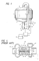
- the turbocharger in accordance with the present invention is represented generically by reference numeral 10.
- This turbocharger 10 includes a turbine 2 driven by an exhaust gas of an engine 1, a compressor which supercharges air when driven by the turbine 2 and an A.C. motor-generator 4 driven by the turbine 2.
- This A.C. motor-generator operates as a generator for generating A.C. power or as a motor generating mechanical power upon receipt of the A.C. power and is a ultra-high speed motor-generator permitting the revolution of the shaft 6 at about 100,000 rpm.
- an exhaust blade or a turbine blade 14 is disposed inside a turbine housing 22.
- a temperature sensor 30 for detecting the temperature of the housing 22 is placed therein.
- An impeller 15 is disposed inside a compressor housing 23 of the compressor 3.
- a compressor scroll 27 of the compressor 3 is communicated with an intake manifold 8 of the engine 1 through an intake pipe 9.
- the turbine blade 14 and the impeller are coupled by the shaft 6.
- the impeller 15 is fixed to one of the ends of the shaft 6 of the turbocharger 10 through a compressor shaft portion 24 which is integral with the shaft 6 and the turbine blade 14 is fixed to the other end of the shaft 6 through a turbine shaft 25.
- the A.C. generator-motor 4 which is disposed at an intermediate portion of the shaft 6 coupling the turbine blade 14 and the impeller 15 has the same construction and function as the motor-generator disclosed in the turbocharger of an internal combustion engine of the afore-mentioned Japanese Patent Laid-Open No. 195329/1985 filed by the inventor of the present invention. This A.C.
- generator-motor 4 consists of a magnetic rotor 16 made of a permanent magnet fitted to the shaft 6, that penetrates through the interior of the center housing 26, and extending in an axial direction, and a stator coil 17 including a reduced thickness pipe, a stator core, and the like.
- the shaft 6 of the turbocharger 10 is supported rotatably by bearings 18 that are fitted to the center housing 26.
- the turbine blade 14 receives the flow of the exhaust gas sent from a direction represented by arrow A through the exhaust manifold 7 of the engine 1, that is, the exhaust gas energy, and rotates, and the exhaust gas is discharged in the axial direction, that is, in the direction represented by arrow B.
- the impeller 15 of the compressor 3 pressure-converts the air introduced from the intake port 28 into the compressor scroll 27 by a diffuser as represented by arrow C and sends it into the intake manifold 8 of the engine 1 through the pair path, that is, the intake pipe 9.
- the intake pipe 9 and the exhaust manifold 7 are communicated with each other through the pipe 11 and moreover, a change-over valve 12 is disposed in this pipe 11. It is of course possible, at times, to directly connect the outlet of the compressor 3 to the inlet of the turbine 2 by a pipe equipped with the change-over valve 12.
- This A.C. generator-motor 4 is controlled by a controller 5, is driven by the turbine 2 to induce a voltage in the stator coil 17 and returns this voltage to the power supply side. It functions as a generator which charges a regenerated voltage in a battery 13 and also as a motor which receives the A.C. power from the battery 13.
- the shaft 6 is supported in the center housing 26 by the bearings 18 and this bearing 18 is lubricated by a lubricating oil supplied from a lubricant supply path 19 communicating with a lubricant supply source such as an oil gallery.
- a lubricant supply source such as an oil gallery.
- An oil reservoir is disposed in the lubricant supply path 19 above the bearings 18 and the lubricating oil staying in the oil reservoir is supplied by its own weight or a natural drop. It is of course possible to dispose lubricant supply means such as a lubricant supply pump for lubricating the bearing 18 supporting the shaft 6 and to circulate and supply forcedly the lubricating oil to the bearing 18.
- any bearing may be employed so long as it can withstand the revolution of the shaft 6 at about 150,000 rpm and can support the shaft 6 while positioned between the turbine blade 14 and the A.C. generator-motor 4.
- the bearing to be used is not particularly limitative.
- the bearing 18 consists of a bearing member 29 which is either fixed or fitted idlely to the center housing 26 and a pair of floating bearing members 31 which are fitted idlely to the inner peripheral surface of the bearing member 29. Therefore, the lubricating oil from the oil reservoir 20 is supplied to the shaft 6, to the floating members 31 and to the gap between the bearing members 29 and at times, to the gap between the center housing 26 and the bearing members 29, through the lubricant supply path 19 formed in the center housing 29, the lubricant supply path 32 formed in the bearing member 29 and the lubricant supply path 33 formed in the floating bearing member.
- the shaft 6 rotates at about 150,000 rpm
- the floating bearing members 31 rotate at about 70,000 rpm.
- the bearing member 29 rotates at about 10,000 to about 30,000 rpm, so that the shaft 6 is supported rotatably under the good condition.
- turbocharger 10 of the present invention operates while the engine 1 is driven, that a voltage is induced in the stator coil 17 by the turbine 2 by driving the A.C. generator-motor 4, is returned to the power source side and is charged to the battery 13 or the generator-motor is utilized as the generator which can use the regenerated voltage for charging the battery or can utilize it as the load, and that the A.C. generator-motor is used as the motor by receiving the A.C. power from the battery, are the same as in the turbocharger disclosed in the afore-mentioned reference Japanese Patent Laid-Open No. 195329/1985. Accordingly, the explanation of these operations will be hereby omitted.
- the turbocharger in accordance with the present invention has its feature in the following operation. Namely, if the temperature T of the turbine housing T rises above a predetermined temperature To while the engine 1 is at halt, the A.C. power is supplied from the battery 13 to the A.C. generator-motor 4 by the control of the controller 5 so as to operate the A.C. generator-motor 4 as the motor. Since the A.C. generator-motor 4 operates as the motor, the air is sent from the compressor 3 to the turbine 2 so that the turbine 2 consisting of the turbine blade 14, the turbine shaft 25 and the turbine housing 22, and the shaft 6 as well as the center housing 26 are cooled.
- the temperature sensor 30 disposed in the turbine housing 22 detects the temperature T of the turbine housing 22.
- the temperature sensor 30 can be disposed at various positions, and is disposed inside the turbine housing 22 in this embodiment (step 51).
- the processing is complete because there is no need to operate the A.C. generator-motor 4.
- the flow proceeds (step 52) to the next processing (step 53) in order to operate the A.C. generator-motor 4 as the motor.
- the change-over valve 12 disposed in the pipe 11 that communicates the intake pipe 9 with the exhaust manifold 7 is opened and the discharge port of the compressor 3 and the intake port of the turbine scroll 21 are communicated so that the air or the cooling air can be introduced (step 53).
- the timer is turned ON to supply the power to the A.C. generator-motor for a predetermined set time to operate it as the motor (steps 54 and 55).
- the shaft 6 rotates to rotate the impeller 15 of the compressor 3 and to operate the turbine blade 14 of the turbine 2.
- the air is sucked from the intake port 28 (in the direction represented by the arrow C) of the compressor 3, then sent into the exhaust manifold 7 from the compressor scroll 27 through the intake pipe 9 and the pipe 11, then into the turbine 2 from the exhaust manifold 7 through the turbine scroll 21 as represented by the arrow A and thereafter discharged from the discharge port as represented by the arrow B after cooling the turbine blade 14 (step 56).
- the counter When the turbine blade 14 of the turbine 2 does not operate, the counter counts the number of times of tries N and so long as this number of times of tries N is smaller than a predetermined number of times of tries N1, the processing returns to the first step 50 and each processing is repeated (steps 63 and 64).
- the oil tank is opened so as to supply the lubricating oil from the oil reservoir 20 through the lubricant supply path 19 to lubricate the bearings 18. It is possible in this case to dispose a valve at the supply port of the oil reservoir 20 to make ON/OFF control of the valve or to lubricate the bearings 18 by use of an ordinary lubrication system.
- the oil reservoir 20 is disposed above the bearings 18 so that the lubricating oil drops naturally and self-lubricates the bearings 18. Moreover, since the shaft 6 is rotating, the lubricating oil is absorbed by the bearings 18 and lubrication can be made sufficiently to the bearings 18 (step 57).
- the turbine 2 As the air is sent into the turbine housing 22, the turbine 2, particularly the turbine housing 22, the turbine blade 14 and the turbine shaft 25, and along therewith, the shaft 6 and the center housing 26, are cooled.
- the A.C. generator-motor 4 When the A.C. generator-motor 4 is operated as the motor for a predetermined period, the estimated time which can cool the turbine 2 is set temporarily to the timer and after the passage of the predetermined time set by the timer, the timer is turned OFF (step 58).
- the temperature T of the housing 22 is detected once again and is compared with the predetermined temperature To in order to judge if T ⁇ To (step 59).
- the counter When the temperature T of the housing 22 is still higher than the predetermined temperature To, the counter counts the number of times of tries n and when the number of times of tries n is smaller than the predetermined number of times of tries n1, the processing returns to the first step 50 and each processing is repeated. However, when the number of times of tries n is greater than the predetermined number of tries n1, the processing is completed assuming that the temperature of the turbine 2 such as the temperature of the turbine housing 22 has already been below the predetermined temperature To (steps 65 and 66).
- the oil tank is closed and the supply of the lubricating oil from the oil reservoir to the bearing 18 is stopped (step 61).
- the change-over valve 12 disposed in the pipe 11 is switched and closed to cut off the communication between the intake pipe 9 and the exhaust manifold 7, thereby establishing the state where the next operation of the engine 1 can be made (step 62).
- the operation of the A.C. generator-motor 4 as the motor is stopped.
- the temperature of the turbine 2 is below the predetermined temperature To and when the engine starts again, however, the cooling operation of the turbine 2 is stopped and returns to the original state.
- the operation of the turbocharger described above is controlled by the steps of limiting temporarily the operation time by use of the timer, detecting once again the temperature of the turbine 2 by the temperature sensor 30 after the set operation time by the timer is complete, comparing it with the predetermined set temperature To and judging whether the cooling operation is continued or stopped. Accordingly, it is possible to detect reliably the drop of the temperature of the turbine 2 or the like.
- the turbocharger 10 since the turbocharger 10 is equipped with the self-cooling system, the turbine 2 can be cooled even when the engine 1 comes to halt after the turbocharger 10 is operated under the high load state and the turbine 2 rises to the high temperature by receiving the heat of the exhaust gas energy of the engine 1. Accordingly, the permanent magnet of the A.C. generator-motor is not affected adversely by the heat from the turbine 2 and the demagnetization of the permanent magnet does not occur. Moreover, the rotation of the shaft 6 does not stop while the shaft 6 and the bearings 18 are at the high temperature so that the lubricating oil supplied to the bearings 18 is neither solidified nor carbonized, and seizure does not occur, either. Accordingly, the turbocharger of the present invention is extremely effective as a seizure prevention apparatus of the turbocharger, too.
Abstract
Description
- This invention relates to a turbocharger applied to a car engine.
- A turbocharger which can provide supercharging of a suitable and sufficient quantity of air in a wide range of a low speed to a high speed in an internal combustion engine equipped with a turbocharger has been disclosed, for example, in Japanese Patent Laid-Open No. 195329/1985 filed by the inventor of the present invention. The turbocharger of this prior art will be described with reference to Fig. 4 of the accompanying drawings. The
turbocharger 40 of the internal combustion engine includes aturbine 41 which is driven by the exhaust gas energy of the internal combustion engine and acompressor 42 which super-charges air into a cylinder when driven by theturbine 41, and further includes a motor-generator 43 which is driven by theturbine 41. Theturbine 41, the motor-generator 43 and thecompressor 42 are disposed sequentially on ashaft 44. Thisshaft 44 is fitted rotatably to ahousing 48 through abearing 49 and afloating metal 50. The motor-generator 43 consists of amagnetic rotor 46 fixed to theshaft 44 and astator coil 47 fitted to thehousing 48 and is operated as a motor or a generator in accordance with the operating condition of the internal combustion engine. The motor-generator 43 is operated as the motor in at least the low speed/high load operating range of the internal combustion engine. - In the
turbocharger 40 of the internal combustion engine described above, theturbine 41 receives the heat energy from the exhaust gas energy and attains a high temperature. However, since the A.C. generator-motor, that is, the motor-generator 43 equipped with themagnetic rotor 46 consisting of a permanent magnet, is disposed on theshaft 44 that connects and drives theturbine 41 and thecompressor 42, themagnetic rotor 46 disposed between theturbine 41 and thecompressor 42 is affected by the heat of theturbine 41 or the heat transferred thereto by heat transfer and radiation through theturbine blade 45 and theshaft 44 when theturbine 41 reaches a high temperature. Here, the problem develops in that themagnetic rotor 46 made of the permanent magnet in the motor-generator 43 is not much resistant to the heat of high temperature. In other words, the permanent magnet is very weak to the heat and when the temperature is about 200°C or more, its demagnetizing factor gets deteriorated drastically. For example, the demagnetizing factor is about 5% at about 200°C but is as high as about 30% at about 300°C. If the turbocharger is stopped rapidly particularly when it is operated at a high load, the overall temperature becomes so high that the A.C. magnetic rotor as the permanent manget is demagnetized disadvantageously. For instance, there is the possibility that the permanent magnet gets demagnetized by the heat of the exhaust system of the engine when the engine stops after the car drives on a highway and comes to halt, for example. - Furthermore, a lubricating oil for lubricating the
bearings 49 and thefloating metal 50 that support the shaft of theturbocharger 40 is carbonized and adheres by the heat from theturbine 41 receiving the exhaust gas energy and this adhering lubricating oil brings thebearings 49 and thefloating metal 50 into a sticky state. Accordingly, when the turbocharger is operated next, its operation is inhibited. Therefore, in the turbocharger equipped with the A.C. generator-motor in an internal combustion engine, there remains the problem how the bearings supporting the magnetic rotor of the A.C. generator-motor and the shaft can be protected from the heat transferred from the turbine. - It is therefore a main object of the present invention to solve the problems with the prior art described above and to provide a turbocharger which dissipates the heat transferred through conduction and radiation from a turbine which attains a high temperature on receiving the heat of an exhaust gas, by blowing air or cooling air to the turbocharger even after driving of the turbocharger in a high load state in an internal combustion engine thereby to cool the turbine and to protect a magnetic rotor consisting of a permanent magnet and disposed on a shaft between the turbine and a compressor from the high heat of the turbine, rotates the shaft of the turbocharger while the turbine is at a high temperature so as to lubricate bearings and to protect carbonization and adherence of the lubricating oil due to the stop of operation and seizure of the bearings.
- It is therefore an object of the present invention to provide a turbocharger characterized in that an A.C. generator-motor is disposed on a shaft equipped with a turbine blade at one of its ends and with an impeller at the other and supporting them through bearings, control is made so as to operate the A.C. generator-motor as a motor when the temperature of a turbine is above a predetermined set temperature after the stop of operation of an engine, the impeller of a compressor and the turbine blade fitted to the shaft are subsequently rotated even though the engine is stopped after the turbocharger is operated at a high load (in this case, the shaft rotates at a very high speed of above about 100,000 rpm, for example), the air or cooling air is sent into the turbine from the compressor through an exhaust pipe, more difinitely, through a pipe connecting directly the compressor to the turbine, so as to dissipate the heat of the turbine and to cool the turbine.
- It is another object of the present invention to provide a turbocharger characterized in that a valve is disposed in the pipe connecting directly an intake pipe to an exhaust pipe, control is made so as to open this valve when the A.C. generator-motor is operated as a motor when the temperature of a housing is above the predetermined set temperature after the stop of operation of the engine, and cold air is forcedly fed into the turbine to promote cooling of the turbine.
- It is still another object of the present invention to provide a turbocharger characterized in that the operation time of the A.C. generator-motor is set by a timer, the A.C. generator-motor is stopped automatically after it is operated for a predetermined period and the turbine is cooled, and at times, the temperature of the housing such as a turbine housing is detected to make control so that the A.C. generator-motor is operated as a motor until the temperature of the housing falls below the predetermined set temperature.
- It is still another object of the present invention to provide a turbocharger characterized in that a lubrication system for lubricating the bearings during the operation period of the A.C. generator-motor as a motor in the turbocharger is forcedly actuated or an oil reservoir is disposed above a lubrication path of a lubricating oil for the bearings, the lubricating oil is absorbed by the bearings for self-lubrication by the natural drop of the lubricating oil with the rotation of the shaft, so as to prevent carbonization of the lubricating oil due to the heat and its adhesion to the bearings and to the shaft, as well as the burining loss and increase in resistance, and to prevent seizure of the shaft and the bearings and any disadvantages when the turbocharger is operated when the engine is driven.
- It is still another object of the present invention to provide a turbocharger characterized in that the temperature of the A.C. generator-motor consisting of the shaft and a permanent magnet transferred thereto from the turbine through the shaft is reduced so that the heat from the turbine to the A.C. generator-motor including the permanent magnet is dissipated completely, the A.C. generator-motor consisting of the permanent magnet is free from the adverse influences of the heat, the original function of the permanent magnet is exhibited fully and the A.C. generator-motor has high durability.
-
- Fig. 1 is a schematic view showing a turbocharger in accordance with one embodiment of the present invention;
- Fig. 2 is a sectional view of the principal portions of Fig. 1;
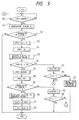
- Fig. 3 is a flowchart useful for explaining the operation of the turbocharger of the present invention; and
- Fig. 4 is a sectional view showing a heretofore known turbocharger of an internal combustion engine.
- Hereinafter, the turbocharger in accordance with one embodiment of the present invention will be described in detail with reference to the accompanying drawings.
- In Figs. 1 and 2, the turbocharger in accordance with the present invention is represented generically by
reference numeral 10. Thisturbocharger 10 includes aturbine 2 driven by an exhaust gas of anengine 1, a compressor which supercharges air when driven by theturbine 2 and an A.C. motor-generator 4 driven by theturbine 2. This A.C. motor-generator operates as a generator for generating A.C. power or as a motor generating mechanical power upon receipt of the A.C. power and is a ultra-high speed motor-generator permitting the revolution of the shaft 6 at about 100,000 rpm. As to theturbine 2, an exhaust blade or aturbine blade 14 is disposed inside aturbine housing 22. Atemperature sensor 30 for detecting the temperature of thehousing 22 is placed therein. Animpeller 15 is disposed inside acompressor housing 23 of thecompressor 3. A compressor scroll 27 of thecompressor 3 is communicated with anintake manifold 8 of theengine 1 through anintake pipe 9. - Furthermore, the
turbine blade 14 and the impeller are coupled by the shaft 6. In other words, theimpeller 15 is fixed to one of the ends of the shaft 6 of theturbocharger 10 through acompressor shaft portion 24 which is integral with the shaft 6 and theturbine blade 14 is fixed to the other end of the shaft 6 through aturbine shaft 25. The A.C. generator-motor 4 which is disposed at an intermediate portion of the shaft 6 coupling theturbine blade 14 and theimpeller 15 has the same construction and function as the motor-generator disclosed in the turbocharger of an internal combustion engine of the afore-mentioned Japanese Patent Laid-Open No. 195329/1985 filed by the inventor of the present invention. This A.C. generator-motor 4 consists of amagnetic rotor 16 made of a permanent magnet fitted to the shaft 6, that penetrates through the interior of thecenter housing 26, and extending in an axial direction, and astator coil 17 including a reduced thickness pipe, a stator core, and the like. - The shaft 6 of the
turbocharger 10 is supported rotatably bybearings 18 that are fitted to thecenter housing 26. Theturbine blade 14 receives the flow of the exhaust gas sent from a direction represented by arrow A through theexhaust manifold 7 of theengine 1, that is, the exhaust gas energy, and rotates, and the exhaust gas is discharged in the axial direction, that is, in the direction represented by arrow B. Theimpeller 15 of thecompressor 3 pressure-converts the air introduced from theintake port 28 into thecompressor scroll 27 by a diffuser as represented by arrow C and sends it into theintake manifold 8 of theengine 1 through the pair path, that is, theintake pipe 9. Theintake pipe 9 and theexhaust manifold 7 are communicated with each other through thepipe 11 and moreover, a change-overvalve 12 is disposed in thispipe 11. It is of course possible, at times, to directly connect the outlet of thecompressor 3 to the inlet of theturbine 2 by a pipe equipped with the change-overvalve 12. This A.C. generator-motor 4 is controlled by acontroller 5, is driven by theturbine 2 to induce a voltage in thestator coil 17 and returns this voltage to the power supply side. It functions as a generator which charges a regenerated voltage in abattery 13 and also as a motor which receives the A.C. power from thebattery 13. - The shaft 6 is supported in the
center housing 26 by thebearings 18 and this bearing 18 is lubricated by a lubricating oil supplied from alubricant supply path 19 communicating with a lubricant supply source such as an oil gallery. An oil reservoir is disposed in thelubricant supply path 19 above thebearings 18 and the lubricating oil staying in the oil reservoir is supplied by its own weight or a natural drop. It is of course possible to dispose lubricant supply means such as a lubricant supply pump for lubricating thebearing 18 supporting the shaft 6 and to circulate and supply forcedly the lubricating oil to thebearing 18. In this case, any bearing may be employed so long as it can withstand the revolution of the shaft 6 at about 150,000 rpm and can support the shaft 6 while positioned between theturbine blade 14 and the A.C. generator-motor 4. In other words, the bearing to be used is not particularly limitative. - For example, the
bearing 18 consists of abearing member 29 which is either fixed or fitted idlely to thecenter housing 26 and a pair of floating bearingmembers 31 which are fitted idlely to the inner peripheral surface of thebearing member 29. Therefore, the lubricating oil from theoil reservoir 20 is supplied to the shaft 6, to the floatingmembers 31 and to the gap between thebearing members 29 and at times, to the gap between thecenter housing 26 and thebearing members 29, through thelubricant supply path 19 formed in thecenter housing 29, thelubricant supply path 32 formed in thebearing member 29 and thelubricant supply path 33 formed in the floating bearing member. When the shaft 6 rotates at about 150,000 rpm, for example, the floating bearingmembers 31 rotate at about 70,000 rpm. When not fixed to thecenter housing 26, thebearing member 29 rotates at about 10,000 to about 30,000 rpm, so that the shaft 6 is supported rotatably under the good condition. - Next, the operation of the
turbocharger 10 of the present invention and its control will be described with reference to Figs. 1, 2 and 3. Incidentally, the technical facts that theturbocharger 10 operates while theengine 1 is driven, that a voltage is induced in thestator coil 17 by theturbine 2 by driving the A.C. generator-motor 4, is returned to the power source side and is charged to thebattery 13 or the generator-motor is utilized as the generator which can use the regenerated voltage for charging the battery or can utilize it as the load, and that the A.C. generator-motor is used as the motor by receiving the A.C. power from the battery, are the same as in the turbocharger disclosed in the afore-mentioned reference Japanese Patent Laid-Open No. 195329/1985. Accordingly, the explanation of these operations will be hereby omitted. - The turbocharger in accordance with the present invention has its feature in the following operation. Namely, if the temperature T of the turbine housing T rises above a predetermined temperature To while the
engine 1 is at halt, the A.C. power is supplied from thebattery 13 to the A.C. generator-motor 4 by the control of thecontroller 5 so as to operate the A.C. generator-motor 4 as the motor. Since the A.C. generator-motor 4 operates as the motor, the air is sent from thecompressor 3 to theturbine 2 so that theturbine 2 consisting of theturbine blade 14, theturbine shaft 25 and theturbine housing 22, and the shaft 6 as well as thecenter housing 26 are cooled. - An example of the operation control of the turbocharger in accordance with the present invention will be described with reference to the flowchart of Fig. 3.
- It will be assumed, first of all, that the
engine 1 comes to halt after the car drives on a highway, for example, and theengine 1, and hence, theturbocharger 10, is operated at a high load. In this case, whether or not the engine is at halt is judged and when it is, the processing moves to the next step (step 51) and if it is not, the processing returns to the first step (step 50). - When the
engine 1 is at halt, thetemperature sensor 30 disposed in theturbine housing 22 detects the temperature T of theturbine housing 22. Incidentally, thetemperature sensor 30 can be disposed at various positions, and is disposed inside theturbine housing 22 in this embodiment (step 51). - Whether or not the temperature of the
turbine housing 22, that is, theturbine 2, rises to a high temperature is judged and when it is lower than the predetermined preset temperature To, the processing is complete because there is no need to operate the A.C. generator-motor 4. When it is higher than the preset temperature To, on the other hand, the flow proceeds (step 52) to the next processing (step 53) in order to operate the A.C. generator-motor 4 as the motor. - The change-over
valve 12 disposed in thepipe 11 that communicates theintake pipe 9 with theexhaust manifold 7 is opened and the discharge port of thecompressor 3 and the intake port of theturbine scroll 21 are communicated so that the air or the cooling air can be introduced (step 53). - The timer is turned ON to supply the power to the A.C. generator-motor for a predetermined set time to operate it as the motor (
steps 54 and 55). - When the operation of the A.C. generator-
motor 4 as the motor is started, the shaft 6 rotates to rotate theimpeller 15 of thecompressor 3 and to operate theturbine blade 14 of theturbine 2. Here, whether or not theturbine blade 14 starts operating is judged and when it rotates, the air is sucked from the intake port 28 (in the direction represented by the arrow C) of thecompressor 3, then sent into theexhaust manifold 7 from thecompressor scroll 27 through theintake pipe 9 and thepipe 11, then into theturbine 2 from theexhaust manifold 7 through theturbine scroll 21 as represented by the arrow A and thereafter discharged from the discharge port as represented by the arrow B after cooling the turbine blade 14 (step 56). - When the
turbine blade 14 of theturbine 2 does not operate, the counter counts the number of times of tries N and so long as this number of times of tries N is smaller than a predetermined number of times of tries N₁, the processing returns to thefirst step 50 and each processing is repeated (steps 63 and 64). - However, if the
turbine blade 14 does not operate even though the number of times of tries N is greater than the predetermined number of times of tries N₁, judgement is made to the effect that any abnormality occurs in the turbocharger, an abnormality signal is raised to complete the processing and inspection and repair is carried out (step 67). - Simultaneously with the start of the operation of the
turbine blade 14, the oil tank is opened so as to supply the lubricating oil from theoil reservoir 20 through thelubricant supply path 19 to lubricate thebearings 18. It is possible in this case to dispose a valve at the supply port of theoil reservoir 20 to make ON/OFF control of the valve or to lubricate thebearings 18 by use of an ordinary lubrication system. In the embodiment shown in the drawing, theoil reservoir 20 is disposed above thebearings 18 so that the lubricating oil drops naturally and self-lubricates thebearings 18. Moreover, since the shaft 6 is rotating, the lubricating oil is absorbed by thebearings 18 and lubrication can be made sufficiently to the bearings 18 (step 57). - As the air is sent into the
turbine housing 22, theturbine 2, particularly theturbine housing 22, theturbine blade 14 and theturbine shaft 25, and along therewith, the shaft 6 and thecenter housing 26, are cooled. When the A.C. generator-motor 4 is operated as the motor for a predetermined period, the estimated time which can cool theturbine 2 is set temporarily to the timer and after the passage of the predetermined time set by the timer, the timer is turned OFF (step 58). - Here, the temperature T of the
housing 22 is detected once again and is compared with the predetermined temperature To in order to judge if T < To (step 59). - When the temperature T of the
housing 22 is lower than the predetermined temperature To, the operation of the A.C. generator-motor 4 is stopped (step 60). - When the temperature T of the
housing 22 is still higher than the predetermined temperature To, the counter counts the number of times of tries n and when the number of times of tries n is smaller than the predetermined number of times of tries n₁, the processing returns to thefirst step 50 and each processing is repeated. However, when the number of times of tries n is greater than the predetermined number of tries n₁, the processing is completed assuming that the temperature of theturbine 2 such as the temperature of theturbine housing 22 has already been below the predetermined temperature To (steps 65 and 66). - When the operation of the A.C. generator-
motor 4 is stopped, theimpeller 15 of thecompressor 3 and theturbine blade 14 of theturbine 2 stop their rotation (step 60). - Furthermore, the oil tank is closed and the supply of the lubricating oil from the oil reservoir to the
bearing 18 is stopped (step 61). - The change-over
valve 12 disposed in thepipe 11 is switched and closed to cut off the communication between theintake pipe 9 and theexhaust manifold 7, thereby establishing the state where the next operation of theengine 1 can be made (step 62). - Here, the operation of the A.C. generator-
motor 4 as the motor is stopped. When the temperature of theturbine 2 is below the predetermined temperature To and when the engine starts again, however, the cooling operation of theturbine 2 is stopped and returns to the original state. This control will be obvious to those skilled in the art. The operation of the turbocharger described above is controlled by the steps of limiting temporarily the operation time by use of the timer, detecting once again the temperature of theturbine 2 by thetemperature sensor 30 after the set operation time by the timer is complete, comparing it with the predetermined set temperature To and judging whether the cooling operation is continued or stopped. Accordingly, it is possible to detect reliably the drop of the temperature of theturbine 2 or the like. - As described above, since the
turbocharger 10 is equipped with the self-cooling system, theturbine 2 can be cooled even when theengine 1 comes to halt after theturbocharger 10 is operated under the high load state and theturbine 2 rises to the high temperature by receiving the heat of the exhaust gas energy of theengine 1. Accordingly, the permanent magnet of the A.C. generator-motor is not affected adversely by the heat from theturbine 2 and the demagnetization of the permanent magnet does not occur. Moreover, the rotation of the shaft 6 does not stop while the shaft 6 and thebearings 18 are at the high temperature so that the lubricating oil supplied to thebearings 18 is neither solidified nor carbonized, and seizure does not occur, either. Accordingly, the turbocharger of the present invention is extremely effective as a seizure prevention apparatus of the turbocharger, too.
Claims (14)
a turbine equipped with a turbine blade connected to an exhaust pipe of an engine and driven by exhaust gas energy of said engine;
a compressor equipped with an impeller connected to an intake pipe of said engine and supercharges intake air into said engine when driven by said turbine;
a shaft having said turbine blade fixed at one of the ends thereof and said impeller fixed at the other end thereof;
a housing supporting rotatably said shaft through bearings;
an A.C. generator-motor equipped with a magnetic rotor fixed to said shaft and with a stator coil fitted to said housing, and operated either as a motor or as a generator;
a battery connected to said A.C. generator-motor;
temperature detection means for detecting the temperature of said turbine; and
control means for supplying the power from said battery to said A.C. generator-motor and operating said A.C. generator-motor as the motor when a temperature signal from said temperature detection means is above a predetermined set temperature after the stop of said engine.
Applications Claiming Priority (2)
| Application Number | Priority Date | Filing Date | Title |
|---|---|---|---|
| JP203142/87 | 1987-08-17 | ||
| JP62203142A JPS6445922A (en) | 1987-08-17 | 1987-08-17 | Turbocharger |
Publications (2)
| Publication Number | Publication Date |
|---|---|
| EP0304259A1 true EP0304259A1 (en) | 1989-02-22 |
| EP0304259B1 EP0304259B1 (en) | 1992-01-02 |
Family
ID=16469111
Family Applications (1)
| Application Number | Title | Priority Date | Filing Date |
|---|---|---|---|
| EP88307556A Expired - Lifetime EP0304259B1 (en) | 1987-08-17 | 1988-08-15 | Turbocharger |
Country Status (4)
| Country | Link |
|---|---|
| US (1) | US4884406A (en) |
| EP (1) | EP0304259B1 (en) |
| JP (1) | JPS6445922A (en) |
| DE (2) | DE304259T1 (en) |
Cited By (19)
| Publication number | Priority date | Publication date | Assignee | Title |
|---|---|---|---|---|
| GB2335710A (en) * | 1998-03-27 | 1999-09-29 | Aisin Seiki | Hybrid turbocharger with air bearings |
| EP0956435A1 (en) * | 1996-12-20 | 1999-11-17 | Turbodyne Systems Inc. | Bearing systems for motor-assisted turbochargers for internal conbusion engines |
| WO2004093294A1 (en) * | 2003-04-15 | 2004-10-28 | Honeywell International Inc. | Electric motor cartridge for an electrically assisted turbocharger |
| WO2005064135A2 (en) * | 2003-12-20 | 2005-07-14 | Honeywell International Inc. | Center housing design for electric assisted turbocharger |
| WO2008023067A1 (en) * | 2006-08-24 | 2008-02-28 | Abb Turbo Systems Ag | Emergency oil tank |
| EP2025891A1 (en) * | 2006-06-02 | 2009-02-18 | IHI Corporation | Electric supercharger |
| EP1811150A3 (en) * | 2006-01-24 | 2009-03-25 | IHI Corporation | Motor-Driven supercharge |
| US7530230B2 (en) | 2005-08-05 | 2009-05-12 | Ihi Corporation | Supercharger with electric motor |
| US7559751B2 (en) | 2005-08-22 | 2009-07-14 | Ihi Corporation | Supercharger with electric motor |
| FR2934639A1 (en) * | 2008-07-30 | 2010-02-05 | Renault Sas | Engine i.e. turbocharged engine, hot shutdowns counting method for motor vehicle, involves incrementing counter that counts number of hot shutdowns of engine of motor vehicle, to one unit if gas temperature is higher than threshold value |
| US7837448B2 (en) | 2006-01-26 | 2010-11-23 | Ishikawajima-Harima Heavy Industries Co., Ltd. | Supercharger |
| US8001781B2 (en) | 2006-06-02 | 2011-08-23 | Ihi Corporation | Motor-driven supercharger |
| US8152489B2 (en) | 2006-08-18 | 2012-04-10 | Ihi Corporation | Motor-driven supercharger |
| US8157544B2 (en) | 2006-08-18 | 2012-04-17 | Ihi Corporation | Motor driven supercharger with motor/generator cooling efficacy |
| US8157543B2 (en) | 2006-03-23 | 2012-04-17 | Ihi Corporation | High-speed rotating shaft of supercharger |
| FR3048035A1 (en) * | 2016-02-21 | 2017-08-25 | Valeo Systemes De Controle Moteur | ELECTRIC COMPRESSOR |
| CN108474295A (en) * | 2015-12-04 | 2018-08-31 | 三菱重工发动机和增压器株式会社 | Turbocharger, engine system, the control method of turbocharger |
| EP3536927A1 (en) * | 2018-03-07 | 2019-09-11 | Mazda Motor Corporation | Supercharging device for engine, engine, method of supercharging engine, and computer program product |
| US11834982B2 (en) * | 2022-02-16 | 2023-12-05 | Transportation Ip Holdings, Llc | Inverted compressor for electric turbocharger |
Families Citing this family (30)
| Publication number | Priority date | Publication date | Assignee | Title |
|---|---|---|---|---|
| JPH02241339A (en) * | 1989-03-14 | 1990-09-26 | Hitachi Ltd | Permanent magnet rotor for turbo-charger directly-connecting rotary machine |
| US6135098A (en) * | 1998-10-06 | 2000-10-24 | Engineered Machine Products, Inc. | Flow-through controllable air charger |
| SE514227C2 (en) * | 1999-01-20 | 2001-01-22 | Tore Kaellander | Apparatus adapted to cool a machine assembly adapted to be associated with a motor |
| US6568173B1 (en) * | 2000-08-02 | 2003-05-27 | Ford Global Technologies, Inc. | Control method for turbocharged diesel engine aftertreatment system |
| US6449950B1 (en) * | 2000-09-12 | 2002-09-17 | Honeywell International Inc. | Rotor and bearing system for electrically assisted turbocharger |
| KR20020080973A (en) * | 2001-04-18 | 2002-10-26 | 기아자동차주식회사 | Exhaust gas turbo-charger protecting device |
| US6705084B2 (en) | 2001-07-03 | 2004-03-16 | Honeywell International Inc. | Control system for electric assisted turbocharger |
| US6609375B2 (en) | 2001-09-14 | 2003-08-26 | Honeywell International Inc. | Air cooling system for electric assisted turbocharger |
| GB2400138B (en) * | 2003-04-01 | 2005-04-06 | Visteon Global Tech Inc | Internal combustion engine with turbocharger |
| EP1680858B1 (en) * | 2003-09-19 | 2007-07-18 | Dyson Technology Limited | A rotor assembly |
| KR20060081791A (en) * | 2005-01-10 | 2006-07-13 | 삼성전자주식회사 | Refrigerator apparatus with turbo compressor |
| WO2012051062A2 (en) * | 2010-10-11 | 2012-04-19 | Borgwarner Inc. | Exhaust turbocharger of an internal combustion engine |
| US8935077B2 (en) * | 2011-01-20 | 2015-01-13 | Ecomotors, Inc. | Controlling an engine having an electronically-controlled turbocharger |
| US9488186B2 (en) * | 2011-04-13 | 2016-11-08 | Borgwarner Inc. | Exhaust-gas turbocharger |
| US8959911B2 (en) * | 2011-10-06 | 2015-02-24 | GM Global Technology Operations LLC | Engine assembly including fluid control to boost mechanism |
| DE102013203042A1 (en) * | 2012-04-17 | 2013-10-17 | Ford Global Technologies, Llc | Turbocharger for an internal combustion engine and method for operating a turbocharged internal combustion engine |
| DE102012210320B3 (en) * | 2012-06-19 | 2013-09-26 | Ford Global Technologies, Llc | Liquid-cooled combustion engine for vehicle, has steering valve arranged in connecting line between pump and vent tank and providing enlarged passage area as result of reduced pressure refrigerant in work position |
| CN102943707A (en) * | 2012-10-22 | 2013-02-27 | 安徽中鼎动力有限公司 | Electrically controlled turbocharger |
| US10428734B2 (en) | 2015-02-20 | 2019-10-01 | Pratt & Whitney Canada Corp. | Compound engine assembly with inlet lip anti-icing |
| US10371060B2 (en) | 2015-02-20 | 2019-08-06 | Pratt & Whitney Canada Corp. | Compound engine assembly with confined fire zone |
| US10533492B2 (en) | 2015-02-20 | 2020-01-14 | Pratt & Whitney Canada Corp. | Compound engine assembly with mount cage |
| US9869240B2 (en) | 2015-02-20 | 2018-01-16 | Pratt & Whitney Canada Corp. | Compound engine assembly with cantilevered compressor and turbine |
| US10533500B2 (en) | 2015-02-20 | 2020-01-14 | Pratt & Whitney Canada Corp. | Compound engine assembly with mount cage |
| US10408123B2 (en) * | 2015-02-20 | 2019-09-10 | Pratt & Whitney Canada Corp. | Engine assembly with modular compressor and turbine |
| US20160245162A1 (en) | 2015-02-20 | 2016-08-25 | Pratt & Whitney Canada Corp. | Compound engine assembly with offset turbine shaft, engine shaft and inlet duct |
| JP6794922B2 (en) * | 2017-05-12 | 2020-12-02 | 株式会社豊田自動織機 | Electric supercharger |
| JP2020118042A (en) * | 2019-01-18 | 2020-08-06 | いすゞ自動車株式会社 | Turbosupercharger cooling system and turbosupercharger cooling method |
| JP7103263B2 (en) * | 2019-02-20 | 2022-07-20 | 株式会社豊田自動織機 | Turbo fluid machine |
| US11002181B2 (en) * | 2019-05-03 | 2021-05-11 | Fluid Equipment Development Company, Llc | Method and system for determining a characteristic of a rotating machine |
| CN112211718B (en) * | 2020-09-03 | 2022-04-26 | 潍柴动力股份有限公司 | Method, device and system for protecting supercharger |
Citations (4)
| Publication number | Priority date | Publication date | Assignee | Title |
|---|---|---|---|---|
| GB557261A (en) * | 1942-03-21 | 1943-11-12 | Cyril Henry Bradbury | Improvements in or relating to internal combustion engines employing turbo-compressors |
| EP0096367A2 (en) * | 1982-06-04 | 1983-12-21 | Nissan Motor Co., Ltd. | Apparatus for preventing thermal seizure of a turbo-supercharger drive shaft |
| EP0159146A1 (en) * | 1984-03-17 | 1985-10-23 | Isuzu Motors Limited | Turbocharger for internal combustion engines |
| DE3544247A1 (en) * | 1985-02-15 | 1986-08-28 | Audi AG, 8070 Ingolstadt | Applied-ignition internal combustion engine with exhaust turbocharging |
Family Cites Families (10)
| Publication number | Priority date | Publication date | Assignee | Title |
|---|---|---|---|---|
| JPS4739367Y1 (en) * | 1969-11-20 | 1972-11-29 | ||
| US4363214A (en) * | 1980-07-07 | 1982-12-14 | Kiser Robert W | Turbo-lubrication system |
| JPS58124023A (en) * | 1982-01-18 | 1983-07-23 | Nissan Motor Co Ltd | Bearing device for turbosupercharger |
| JPS58172016U (en) * | 1982-05-13 | 1983-11-17 | 日産自動車株式会社 | Turbocharger cooling system |
| JPS59221427A (en) * | 1983-05-27 | 1984-12-13 | Fuji Heavy Ind Ltd | Cooler for internal-combustion engine with supercharger |
| JPS59221428A (en) * | 1983-05-27 | 1984-12-13 | Fuji Heavy Ind Ltd | Cooler for internal-combustion engine with supercharger |
| JPS6078944U (en) * | 1983-11-07 | 1985-06-01 | 愛三工業株式会社 | Turbocharger oil supply system |
| JPS60195329A (en) * | 1984-03-17 | 1985-10-03 | Isuzu Motors Ltd | Turbocharger for internal-combustion engine |
| JPS61237830A (en) * | 1985-04-11 | 1986-10-23 | Isuzu Motors Ltd | Turbo-charger for internal-combustion engine |
| JPS62186017A (en) * | 1986-02-12 | 1987-08-14 | Komutetsuku:Kk | Protection device for turbocharger |
-
1987
- 1987-08-17 JP JP62203142A patent/JPS6445922A/en active Granted
-
1988
- 1988-08-12 US US07/231,690 patent/US4884406A/en not_active Expired - Fee Related
- 1988-08-15 DE DE198888307556T patent/DE304259T1/en active Pending
- 1988-08-15 DE DE8888307556T patent/DE3867379D1/en not_active Expired - Fee Related
- 1988-08-15 EP EP88307556A patent/EP0304259B1/en not_active Expired - Lifetime
Patent Citations (4)
| Publication number | Priority date | Publication date | Assignee | Title |
|---|---|---|---|---|
| GB557261A (en) * | 1942-03-21 | 1943-11-12 | Cyril Henry Bradbury | Improvements in or relating to internal combustion engines employing turbo-compressors |
| EP0096367A2 (en) * | 1982-06-04 | 1983-12-21 | Nissan Motor Co., Ltd. | Apparatus for preventing thermal seizure of a turbo-supercharger drive shaft |
| EP0159146A1 (en) * | 1984-03-17 | 1985-10-23 | Isuzu Motors Limited | Turbocharger for internal combustion engines |
| DE3544247A1 (en) * | 1985-02-15 | 1986-08-28 | Audi AG, 8070 Ingolstadt | Applied-ignition internal combustion engine with exhaust turbocharging |
Non-Patent Citations (3)
| Title |
|---|
| PATENT ABSTRACTS OF JAPAN, vol. 7, no. 230 (M-249)[1375], 12th October 1983; & JP-A-58 124 023 (NISSAN JIDOSHA K.K.) 23-07-1983 * |
| PATENT ABSTRACTS OF JAPAN, vol. 9, no. 98 (M-375)[1821], 27th April 1985; & JP-A-59 221 427 (FUJI JUKOGYO K.K.) 13-12-1984 * |
| PATENT ABSTRACTS OF JAPAN, vol. 9, no. 98 (M-375)[1821], 27th April 1985; & JP-A-59 221 428 (FUJI JUKOGYO K.K.) 13-12-1984 * |
Cited By (27)
| Publication number | Priority date | Publication date | Assignee | Title |
|---|---|---|---|---|
| EP0956435A1 (en) * | 1996-12-20 | 1999-11-17 | Turbodyne Systems Inc. | Bearing systems for motor-assisted turbochargers for internal conbusion engines |
| EP0956435A4 (en) * | 1996-12-20 | 2002-01-23 | Honeywell Int Inc | Bearing systems for motor-assisted turbochargers for internal conbusion engines |
| GB2335710A (en) * | 1998-03-27 | 1999-09-29 | Aisin Seiki | Hybrid turbocharger with air bearings |
| US7458214B2 (en) | 2003-04-15 | 2008-12-02 | Honeywell International, Inc. | Electric motor cartridge for an electrically assisted turbocharger |
| WO2004093294A1 (en) * | 2003-04-15 | 2004-10-28 | Honeywell International Inc. | Electric motor cartridge for an electrically assisted turbocharger |
| WO2005064135A2 (en) * | 2003-12-20 | 2005-07-14 | Honeywell International Inc. | Center housing design for electric assisted turbocharger |
| WO2005064135A3 (en) * | 2003-12-20 | 2005-09-29 | Honeywell Int Inc | Center housing design for electric assisted turbocharger |
| US7530230B2 (en) | 2005-08-05 | 2009-05-12 | Ihi Corporation | Supercharger with electric motor |
| US7559751B2 (en) | 2005-08-22 | 2009-07-14 | Ihi Corporation | Supercharger with electric motor |
| EP1811150A3 (en) * | 2006-01-24 | 2009-03-25 | IHI Corporation | Motor-Driven supercharge |
| KR100941288B1 (en) | 2006-01-24 | 2010-02-11 | 가부시키가이샤 아이에이치아이 | Motor-driven supercharger |
| US7673452B2 (en) | 2006-01-24 | 2010-03-09 | Ishikawajima-Harima Heavy Industries Co., Ltd. | Motor-driven supercharger |
| US7837448B2 (en) | 2006-01-26 | 2010-11-23 | Ishikawajima-Harima Heavy Industries Co., Ltd. | Supercharger |
| US8157543B2 (en) | 2006-03-23 | 2012-04-17 | Ihi Corporation | High-speed rotating shaft of supercharger |
| EP2025891A1 (en) * | 2006-06-02 | 2009-02-18 | IHI Corporation | Electric supercharger |
| EP2025891A4 (en) * | 2006-06-02 | 2012-12-12 | Ihi Corp | Electric supercharger |
| US8001781B2 (en) | 2006-06-02 | 2011-08-23 | Ihi Corporation | Motor-driven supercharger |
| US8096126B2 (en) | 2006-06-02 | 2012-01-17 | Ihi Corporation | Motor-driven supercharger |
| US8152489B2 (en) | 2006-08-18 | 2012-04-10 | Ihi Corporation | Motor-driven supercharger |
| US8157544B2 (en) | 2006-08-18 | 2012-04-17 | Ihi Corporation | Motor driven supercharger with motor/generator cooling efficacy |
| WO2008023067A1 (en) * | 2006-08-24 | 2008-02-28 | Abb Turbo Systems Ag | Emergency oil tank |
| FR2934639A1 (en) * | 2008-07-30 | 2010-02-05 | Renault Sas | Engine i.e. turbocharged engine, hot shutdowns counting method for motor vehicle, involves incrementing counter that counts number of hot shutdowns of engine of motor vehicle, to one unit if gas temperature is higher than threshold value |
| CN108474295A (en) * | 2015-12-04 | 2018-08-31 | 三菱重工发动机和增压器株式会社 | Turbocharger, engine system, the control method of turbocharger |
| FR3048035A1 (en) * | 2016-02-21 | 2017-08-25 | Valeo Systemes De Controle Moteur | ELECTRIC COMPRESSOR |
| EP3536927A1 (en) * | 2018-03-07 | 2019-09-11 | Mazda Motor Corporation | Supercharging device for engine, engine, method of supercharging engine, and computer program product |
| CN110242401A (en) * | 2018-03-07 | 2019-09-17 | 马自达汽车株式会社 | The supercharging device of engine |
| US11834982B2 (en) * | 2022-02-16 | 2023-12-05 | Transportation Ip Holdings, Llc | Inverted compressor for electric turbocharger |
Also Published As
| Publication number | Publication date |
|---|---|
| DE304259T1 (en) | 1989-11-16 |
| DE3867379D1 (en) | 1992-02-13 |
| JPS6445922A (en) | 1989-02-20 |
| EP0304259B1 (en) | 1992-01-02 |
| US4884406A (en) | 1989-12-05 |
| JPH0525012B2 (en) | 1993-04-09 |
Similar Documents
| Publication | Publication Date | Title |
|---|---|---|
| US4884406A (en) | Turbocharger | |
| US7946118B2 (en) | Cooling an electrically controlled turbocharger | |
| EP0956435B1 (en) | Bearing systems for motor-assisted turbochargers for internal conbusion engines | |
| US5870894A (en) | Motor-assisted supercharging devices for internal combustion engines | |
| EP0323211B1 (en) | Engine room cooling control system | |
| EP0392677B1 (en) | Turbocharger having a bearing device for high speed rotary shaft | |
| US20100175377A1 (en) | Cooling an electrically controlled turbocharger | |
| EP0323212A2 (en) | Cooling control system for internal combustion engines equipped with supercharges | |
| US6871499B1 (en) | Oil pressure detector for electric assisted turbocharger | |
| CN108547678A (en) | A kind of lubricating system, lubrication control method and automobile | |
| EP0085116B1 (en) | Device for driving vacuum pump | |
| JP2557244B2 (en) | Cooling control device for turbocharger and intercooler in internal combustion engine | |
| KR20050039187A (en) | A super charger | |
| JPH07208191A (en) | Turbo-charger | |
| GB2120414A (en) | Automatic control of a cooling system for a turbocharger | |
| KR100444847B1 (en) | Cooling apparatus of turbocharger | |
| JPH0882220A (en) | Turbo charger | |
| JPS58133425A (en) | Bearing protector of turbocharger | |
| JP2000345821A (en) | Abnormality diagnosis device of hydraulic switch of engine and fuel injection control device | |
| GB2086996A (en) | Auxiliary lubrication system for turbo compressors | |
| KR950008312Y1 (en) | Lubricating maintaining device for super charger | |
| JPH08492Y2 (en) | Lubricator for turbocharger | |
| KR960005060Y1 (en) | Protection apparatus of turbo-charger | |
| KR19980048218A (en) | Supercharger protection method and device | |
| KR20060069966A (en) | Controlling device for driving a turbocharger and method for controlling thereof |
Legal Events
| Date | Code | Title | Description |
|---|---|---|---|
| PUAI | Public reference made under article 153(3) epc to a published international application that has entered the european phase |
Free format text: ORIGINAL CODE: 0009012 |
|
| AK | Designated contracting states |
Kind code of ref document: A1 Designated state(s): DE GB |
|
| 17P | Request for examination filed |
Effective date: 19890403 |
|
| DET | De: translation of patent claims | ||
| 17Q | First examination report despatched |
Effective date: 19900308 |
|
| GRAA | (expected) grant |
Free format text: ORIGINAL CODE: 0009210 |
|
| AK | Designated contracting states |
Kind code of ref document: B1 Designated state(s): DE GB |
|
| REF | Corresponds to: |
Ref document number: 3867379 Country of ref document: DE Date of ref document: 19920213 |
|
| PLBE | No opposition filed within time limit |
Free format text: ORIGINAL CODE: 0009261 |
|
| STAA | Information on the status of an ep patent application or granted ep patent |
Free format text: STATUS: NO OPPOSITION FILED WITHIN TIME LIMIT |
|
| 26N | No opposition filed | ||
| PGFP | Annual fee paid to national office [announced via postgrant information from national office to epo] |
Ref country code: GB Payment date: 20010713 Year of fee payment: 14 |
|
| PGFP | Annual fee paid to national office [announced via postgrant information from national office to epo] |
Ref country code: DE Payment date: 20010718 Year of fee payment: 14 |
|
| REG | Reference to a national code |
Ref country code: GB Ref legal event code: IF02 |
|
| PG25 | Lapsed in a contracting state [announced via postgrant information from national office to epo] |
Ref country code: GB Free format text: LAPSE BECAUSE OF NON-PAYMENT OF DUE FEES Effective date: 20020815 |
|
| PG25 | Lapsed in a contracting state [announced via postgrant information from national office to epo] |
Ref country code: DE Free format text: LAPSE BECAUSE OF NON-PAYMENT OF DUE FEES Effective date: 20030301 |
|
| GBPC | Gb: european patent ceased through non-payment of renewal fee |
Effective date: 20020815 |