EP0304258A2 - Dilatation catheter with collapsible outer diameter - Google Patents
Dilatation catheter with collapsible outer diameter Download PDFInfo
- Publication number
- EP0304258A2 EP0304258A2 EP88307551A EP88307551A EP0304258A2 EP 0304258 A2 EP0304258 A2 EP 0304258A2 EP 88307551 A EP88307551 A EP 88307551A EP 88307551 A EP88307551 A EP 88307551A EP 0304258 A2 EP0304258 A2 EP 0304258A2
- Authority
- EP
- European Patent Office
- Prior art keywords
- catheter
- sleeve
- balloon
- shaft
- dilatation
- Prior art date
- Legal status (The legal status is an assumption and is not a legal conclusion. Google has not performed a legal analysis and makes no representation as to the accuracy of the status listed.)
- Ceased
Links
Images


Classifications
-
- A—HUMAN NECESSITIES
- A61—MEDICAL OR VETERINARY SCIENCE; HYGIENE
- A61M—DEVICES FOR INTRODUCING MEDIA INTO, OR ONTO, THE BODY; DEVICES FOR TRANSDUCING BODY MEDIA OR FOR TAKING MEDIA FROM THE BODY; DEVICES FOR PRODUCING OR ENDING SLEEP OR STUPOR
- A61M25/00—Catheters; Hollow probes
- A61M25/10—Balloon catheters
- A61M25/1027—Making of balloon catheters
- A61M25/1029—Production methods of the balloon members, e.g. blow-moulding, extruding, deposition or by wrapping a plurality of layers of balloon material around a mandril
-
- A—HUMAN NECESSITIES
- A61—MEDICAL OR VETERINARY SCIENCE; HYGIENE
- A61M—DEVICES FOR INTRODUCING MEDIA INTO, OR ONTO, THE BODY; DEVICES FOR TRANSDUCING BODY MEDIA OR FOR TAKING MEDIA FROM THE BODY; DEVICES FOR PRODUCING OR ENDING SLEEP OR STUPOR
- A61M25/00—Catheters; Hollow probes
- A61M25/10—Balloon catheters
- A61M25/1027—Making of balloon catheters
- A61M25/1036—Making parts for balloon catheter systems, e.g. shafts or distal ends
-
- A—HUMAN NECESSITIES
- A61—MEDICAL OR VETERINARY SCIENCE; HYGIENE
- A61M—DEVICES FOR INTRODUCING MEDIA INTO, OR ONTO, THE BODY; DEVICES FOR TRANSDUCING BODY MEDIA OR FOR TAKING MEDIA FROM THE BODY; DEVICES FOR PRODUCING OR ENDING SLEEP OR STUPOR
- A61M25/00—Catheters; Hollow probes
- A61M25/10—Balloon catheters
- A61M25/104—Balloon catheters used for angioplasty
-
- A—HUMAN NECESSITIES
- A61—MEDICAL OR VETERINARY SCIENCE; HYGIENE
- A61M—DEVICES FOR INTRODUCING MEDIA INTO, OR ONTO, THE BODY; DEVICES FOR TRANSDUCING BODY MEDIA OR FOR TAKING MEDIA FROM THE BODY; DEVICES FOR PRODUCING OR ENDING SLEEP OR STUPOR
- A61M25/00—Catheters; Hollow probes
- A61M25/10—Balloon catheters
- A61M2025/1043—Balloon catheters with special features or adapted for special applications
- A61M2025/1081—Balloon catheters with special features or adapted for special applications having sheaths or the like for covering the balloon but not forming a permanent part of the balloon, e.g. retractable, dissolvable or tearable sheaths
-
- A—HUMAN NECESSITIES
- A61—MEDICAL OR VETERINARY SCIENCE; HYGIENE
- A61M—DEVICES FOR INTRODUCING MEDIA INTO, OR ONTO, THE BODY; DEVICES FOR TRANSDUCING BODY MEDIA OR FOR TAKING MEDIA FROM THE BODY; DEVICES FOR PRODUCING OR ENDING SLEEP OR STUPOR
- A61M25/00—Catheters; Hollow probes
- A61M25/10—Balloon catheters
- A61M25/1027—Making of balloon catheters
- A61M25/1038—Wrapping or folding devices for use with balloon catheters
Definitions
- the invention relates to improvements in balloon dilatation catheters such as those used in angioplasty procedures and, particularly percutaneous transluminal coronary angioplasty.
- a guide catheter is introduced into the patient's arterial system through the femoral artery and is advanced through the aorta and to the ostium of the coronary artery.
- a balloon dilatation catheter which typically will have been fitted with a small diameter guidewire, such as the steerable guidewire disclosed in U.S. patent no. 4,453,930, is advanced through the guide catheter to and into the coronary artery.
- the catheter is positioned by manipulations of the catheter and the guidewire in which the distal tip of the guidewire is selectively steered through the branches and tortuous passages of the arterial anatomy and with the dilatation catheter being advanced over the guidewire after the guidewire is positioned.
- the balloon When the balloon is positioned in the stenosis, it is inflated under pressure to effect the dilatation, thereby, forcably enlarging the narrowed lumen of the artery.
- the dilatation catheter should be highly flexible so that it can track easily along the guidewire through sharp bends and tortuous coronary arteries. If the catheter is too stiff, it will not track well and instead of following the natural contour of the artery and flexible guidewire, it will tend to straighten the artery which causes it to press against the arterial walls as well as the guidewire which, in turn, presents difficulty in manipulating and positioning the guidewire and catheter. Another difficulty encountered with balloon dilatation catheters is that the presence of the catheter in the artery presents an obstruction to blood flow in the artery.
- the angioplasty procedure typically includes the periodic injection of radiopaque dyes into the coronary arterial tree to enable the physician to observe, fluoroscopically, the condition of the coronary anatomy during the procedure as well as to visualize the anatomy to help in positioning the dilatation catheter. It also is among the common procedures to make measurements of the blood pressure both proximally and distally of the stenosis to compare the pressure gradient in the artery before the dilatation with the pressure gradient after the dilatation. Ideally, the dilatation procedure enlarges the arterial obstruction thereby reducing the pressure gradient along that region. The observation of a reduced pressure gradient signifies that the dilatation procedure is accomplishing its objective and is an important feature to be monitored by the physician.
- the guide catheter is used to inject dye into the coronary arterial tree as well as to make pressure measurements on the proximal side of the stenosis.
- the cross-sectional flow area through the guide catheter be as large as possible.
- it also is desirable to maintain a reduced diameter for the guide catheter so that it will be more easily inserted into the patient and so that the distal end of the guide catheter may be more securely intubated into the coronary ostium. It is among the general objects of the invention to provide a modified dilatation catheter which achieves these objectives.
- the catheter includes a flexible shaft having proximal and distal segments.
- a main lumen and an inflation lumen extend through the shaft.
- the distal segment of the shaft is of reduced diameter.
- the inflation lumen terminates at the juncture of the proximal and distal segments of the shaft.
- the distal segment of the shaft is surrounded by a sleeve formed from a very thin, flexible and strong polymeric material such as highly oriented polyethylene terepthalate and the dilatation balloon is formed integrally with the sleeve.
- the proximal end of the sleeve is attached to the distal portion of the proximal segment of the shaft so that the inflation lumen is in communication with the interior of the sleeve.
- the distal end of the sleeve is attached to the distal region of the distal segment of the catheter shaft.
- Both the sleeve and the balloon are extremely flexible and both are collapsible about the shaft in response to application of a negative pressure to the inflation lumen.
- the thin flexible wall of each of the sleeve and balloon enable them to collapse closely against the smaller diameter of the distal segment of the shaft thereby providing a reduced profile for the distal segment of the catheter when the catheter is in the deflated mode.
- the very thin wall of the sleeve presents negligible bending resistance and enables the distal segment of the catheter to have an extremely high degree of flexibility and superior ability to track over a guidewire even in sharply curved or tortuous blood vessels. Additionally, the low profile of the distal segment of the catheter when the sleeve is collapsed provides for reduced obstruction and increased cross-sectional flow area within the coronary artery in which the catheter is placed.
- the distal segment extends over a length of the order about ten to fifteen centimeters, a distance sufficient to reach the distal extremities of the coronary arterial tree without extending any portion of the proximal region of the catheter shaft out of the guide catheter.
- the collapsible sleeve extends over a greater distance along the catheter and may extend fully to the proximal end of the catheter.
- the outer diameter of the catheter thus is collapsible substantially to the smaller diameter of the shaft to provide an increased annular flow area between the dilatation catheter and the guide catheter.
- the increased flow area inables improved dye injection capability through the guide catheter while the dilatation catheter is in place and also provides for improved pressure measurement through the guide catheter, proximally of the balloon.
- the modified embodiment of the dilatation catheter enables the use of a guide catheter having a smaller diameter without reducing the annular flow area through the guide catheter.
- the use of a smaller guide catheter has advantages in that it is more easily placed and positioned in the patient and reduces the size of the entry site which decreases bleeding and reduces recovery time after the procedure.
- Another object of the invention is to provide a dilatation catheter having superior tracking ability.
- a further object of the invention is to provide a dilatation catheter which has a sufficient stiffness in its proximal segment so that it may be easily pushed over a guidewire yet which displays a high degree of flexibility in its distal segment for superior tracking.
- a further subject of the invention is to provide a dilatation catheter that provides less obstruction to the artery when in a deflated mode.
- Another object of the invention is to provide a dilatation catheter which enables use of a smaller diameter guide catheter.
- a further object of the invention is to provide a dilatation catheter that enables improved proximal dye injection and pressure measurement to be made through a guide catheter, through which the dilatation catheter extends.
- Another object of the invention is to provide a dilatation catheter having an inner shaft portion and an outer tubular sleeve surrounding the inner shaft portion and in which the outer tubular portion is collapsible about the inner shaft in response to negative pressure applied to the sleeve.
- Another object of the invention is to provide an improved catheter adapted for use in percutaneous translumenal angioplasty of the coronary arteries.
- Another object of the invention is to provide a catheter which enables the practice of an improved method of angioplasty and, particularly, angioplasty of the coronary arties.
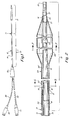
- the balloon dilatation catheter is indicated generally at 10 in Fig. 1 and may be considered as having a proximal segment 11 and a distal segment 13.
- the catheter includes a shaft 12 which may be extruded from an appropriate polymer such as polyvinyl chloride or polyethylene.
- the shaft 12 includes a main, proximal portion which may be considered as having a full diameter 14 and a distal shaft extension 16 of a smaller diameter.
- the proximal shaft portion 14 has a main lumen 18 formed therethrough which continues through the distal shaft segment 16, the main lumen 18 terminating at a distal outlet 20 at the distal tip of the catheter.
- the proximal shaft portion 14 also is provided with an inflation lumen 22 having a smaller cross-sectional area, the inflation lumen 22 terminating at the region of the transition 15 of the proximal segment 11 to the distal segment 13.
- the proximal end of the sleeve 24 is adhesively attached to the proximal shaft portion 14 in the transition region 15 adjacent the distal end of the inflation lumen 22 and is substantially the same outer diameter as the proximal shaft portion 14.
- the distal end of the sleeve 24 is formed to define a reduced diameter neck 26 which is adhesively attached to the distal portion of the distal shaft extension 16.
- a tip marker 27 which may be formed from a band or coil of radiopaque material preferably is mounted on the distal tip of the shaft extension 16.
- An additional radiopaque marker band 29 may be mounted on the distal shaft extension 16 within the region of the balloon to indicate the position of the balloon fluoroscopically during the dilatation procedure.
- the shaft extension 16 may be reinforced with an internally embedded helical coil 31 that extends along the shaft extension 16 to reinforce the shaft extension 16 and prevent it from collapsing under the pressures developed during the dilatation procedure.
- the coil 31 may be embedded in the shaft extension 16 by forming shaft extension from a pair of tubes of plastic (such as polyvinylchloride) with the coil 31 placed between the tubes. The tubes then may be fused together with the coil 31 being embedded in the material.
- the balloon marker 29 also may be attached in the same manner.
- the distal region of the sleeve 24 is formed to define an enlarged diameter dilatation balloon 28.
- the dilatation balloon 28 may be inflated and deflated by applying positive or negative fluid pressure through inflation lumen 22 and the generally annular continuation of the inflation lumen 22 .
- both the balloon 28 and the proximal portion of the sleeve 24 are collapsible about the smaller diameter distal shaft extension 16 when negative pressure is applied to the inflation lumen 22.
- the catheter shaft 12 is provided, at its proximal end, with a bifurcated fitting 30 from which a pair of tubular legs extend, including a main lumen leg 32 which communicates with the main lumen 18 of the catheter and an inflation lumen leg 34 which communicates with the inflation lumen 22 of the catheter.
- a bifurcated fitting 30 from which a pair of tubular legs extend, including a main lumen leg 32 which communicates with the main lumen 18 of the catheter and an inflation lumen leg 34 which communicates with the inflation lumen 22 of the catheter.
- Each of the legs 32, 34 is provided with a luer connector 36, 38 respectively for connection to various adaptors, syringes, inflation devices and the like.
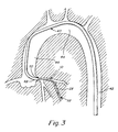
- Fig. 3 illustrates, diagrammatically, the manner in which a dilatation catheter is used with a guide catheter 40 and a small diameter steerable guidewire 52 to place the dilatation catheter 10 in a selected branch of the coronary arterial tree.
- Fig. 3 illustrates the guide catheter 40 as having been placed so as to extend through the aorta 42 and aortic arch 44 and downwardly through the ascending aorta 46 with the distal tip 48 of the guide catheter 40 intubated in the selected coronary ostium 50 at the base of the coronary arterial tree.
- a dilatation catheter 10 having a guidewire 52 in its main lumen 18 with its distal tip protruding distally beyond the distal tip of the catheter 10, is advanced through the guide catheter 40 and beyond the distal tip 48 into the coronary artery.
- the physician may inject radiopaque dye through the guide catheter 40 into the coronary arteries to visual them on a fluoroscope and also may measure the patient's blood pressure proximally of the balloon 28.
- the physician also may inject radiopaque dye from the distal end of the dilatation catheter 10 and also may make distal pressure measurements through the main lumen 18 of the dilatation catheter 10.
- the distal segment 13 and sleeve 24 of the dilatation catheter are sufficiently long so that even when the distal end of the dilatation catheter is extended as far as possible into the coronary arterial tree, the transition region 15 remains inside of the guide catheter 40.
- the sleeve 24 and balloon 28 are formed to be very thin and highly flexible yet sufficiently strong to withstand the pressures developed during dilatation without excessive compliance.
- the sleeve 24 and balloon 28 are formed in a single integral piece from polyethylene terepthalate (PET).
- PET polyethylene terepthalate
- the sleeve 24, including the balloon 28 may be between 10 to 15 centimeters long.
- the balloon 28 may have a wall thickness of the order of 0.0002 inches and a length of about 20 millimeters.
- the portion of the sleeve 24 proximally of the balloon 28 may have a diameter in the order of 0.053 inches, a wall thickness of 0.0005 inches and a length of about ten to thirteen centimeters.
- the integral balloon and sleeve may be formed using methods described in copending application serial no. 001,759 filed January 9, 1987 entitled Thin Wall High Strength Balloon and Method of Manufacture which describes the use of high-stretch ratios and heat setting to provide balloons having surprisingly thin, flexible and strong properties.
- Balloons made in accordance with the techniques described in that application are characterized by a wall thickness to diameter ratio of less than 5.0 x 10 ⁇ 3.
- such balloons may have a radial tensile strength greater than about 35,000 psi.
- a mold as illustrated in Fig. 4 may be used. The mold as shown in Fig.
- the mold 4 includes a mold body 70 having an internal bore which defines the intended dimension of the finished balloon and sleeve.
- the mold also includes a pair of end members including a fixed end member 74 and a movable end member 72. Both end members include outwardly tapering portions 74A, 72A respectively, which merge into smaller diameter end bores 74B, 72B respectively.
- a water jacket 76 having inlet and outlet ports 78, 80 surrounds the mold 70.
- the mold parts are formed from a material such as brass having good heat conductivity.
- the mold 70 receives a tubular parison indicated in phantom at 82 in Fig. 4.
- the parison is gripped at its ends which extend outwardly of the mold, one of the ends being sealed and the other end being connected securely to a source of fluid (such as gas) under pressure as by a fitting 84.
- the clamp 85 and fitting 84 are mounted, by means not shown, to enable them to be drawn upon axially so as to impart an axial stretch to the parison 82.
- the parison is formed from a polymer such as PET and its dimensions are selected with respect to the intended final configuration of the balloon to result in the balloon having the desired properties and dimensions, as described more fully in application serial no. 001,759, reference being made to said application for full details of the procedure.
- the parison is thin walled and after stretching is highly oriented, being stretched radially close to the elastic limit of the material at the inner surface of the tube. Orientation takes place at an elevated temperature that is controlled by a heat transfer of fluids circulated through the water jacket.
- the parison is drawn axially and then, while being so drawn is expanded radially within the mold.
- the orientation takes place at a temperature between the first and second order transition temperatures of the material, preferably at about 90°C for the PET material.
- the starting parison may be a tube of PET having inner diameter of 0.429 millimeters and an outer diameter of 0.638 millimeters.
- the parison may be stretched axially to about 3.1 times its original length. During the axial stretching the parison is expanded radially by admitting gas under pressure into the tubular parison through fitting 84 to stretch the parison to the enlarged diameters as determined by the mold members. After the parison has been radially enlarged to the diameters of the mold the balloon pressure is released and the longitudinal stretching at both ends of the parison is continued.
- the short end of the parison (contained in the movable mold member 72) is held stationary and the long end of the parison (held within fixed mold member 74) is continually drawn to continue to stretch the long portion of the parison that will become the elongate proximal portion of the sleeve 24 of the present invention.
- the stretched and expanded balloon and sleeve is repressurized and is then subjected to a heat setting step in which steam is circulated through the jacket 76 at a temperature above the stretching temperature and is maintained for a time sufficiently to increase the degree of crystalinity in the material.
- the mold is cooled to a temperature less than the second order transition temperature of the material and the balloon and integral sleeve may be removed from the mold.
- the illustrative embodiment of the invention is made using an internal diameter stretch ratio of 7 and an outer diameter stretch ratio of about 4.7 for the balloon.
- the portion of the sleeve proximal of the balloon has an ID stretch ratio of about 3.1 and an OD stretch ratio of about 2.1.
- the catheter having the foregoing construction displays a sleeve 24 that is extremely flexible, thin walled and very strong.
- the sleeve presents minimal resistance to bending which results in a highly flexible distal segment 13 of the catheter.
- the degree of flexibility is such that the entire sleeve is easily collapsible about the distal shaft extension 16.
- Figs. 5 and 6 illustrate, respectively, the expanded and collapsed configurations of the proximal portion of the sleeve 24 and Figs. 7 and 8 similarly illustrate the expanded and collapsed configurations of the balloon portion 28.
- the sleeve 24 is collapsed closely about the distal shaft extension 16 and defines a diameter that is effectively the same as that of the distal shaft extension 16.
- the sleeve 24 forms one or two wings 54 which do not present any significant obstruction to blood flow when the device is in an artery.
- Fig. 8 illustrates the configuration of the collapsed balloon 28. Because the balloon is larger in diameter, it usually will tend to form a pair of very thin wings 55 that may tend to fold over each other, as illustrated.
- Fig. 9 illustrates a modified embodiment of the invention which differs in that the sleeve 24′ extends over the full length. or nearly the full length, of the catheter.
- the full diameter shaft 12′ may be relatively short and may make a transition to a smaller diameter single lumen shaft near the proximal end of the catheter.
- the sleeve 24′ is joined at transition region 15′ to the full diameter shaft and extends over a length that is coextensive with a substantial length of the guide catheter 40 with which the dilatation catheter is to be used.
- the distal segment 13′ of this embodiment is substantially longer than in the embodiment of Fig. 1.
- Fig. 10 illustrates, diagrammatically, how the modified form of the invention provides for increased cross-sectional flow area through the guide catheter.
- the figure illustrates, in solid, the cross-sectional flow area through the generally annular region between the guide catheter 40 and the dilatation catheter 10′ (in solid).
- the circle indicated in phantom at 56 illustrates the normal outer diameter of a conventional non-collapsible dilatation catheter.
- the increased flow area achieved with the present invention is represented by the cross-hatched area 58.
- Fig 11 illustrates the manner in which the invention may be employed to use a smaller diameter guide catheter 40′.
- the collapsibilty of the dilatation catheter enables the required cross-sectional flow area to be achieved within the confines of a smaller diameter guide catheter 40′.
- the use of a smaller diameter guide catheter provides a number of advantages in that it can be inserted percutaneously into the patient through a smaller opening in the patient s blood vessel and it also is more easily and more securely intubated into the coronary ostium.
- the invention provides an improved catheter construction having superior flexibility and trackability. Additionally the collapsibility of the outer diameter of the catheter provides for improved blood perfusion through the coronary arteries. Moreover, the invention may be incorporated in a catheter so as to provide increased cross-sectional flow area when used with a conventional guide catheter or, alternatively, enables the use of a smaller diameter guide catheter.
Abstract
Description
- The invention relates to improvements in balloon dilatation catheters such as those used in angioplasty procedures and, particularly percutaneous transluminal coronary angioplasty.
- In recent years there has been a substantial increase in the use of percutaneous transluminal angioplasty for the treatment of vascular stenoses and, particularly, stenoses of the coronary arteries. The use of balloon dilatation catheters for such angioplasty procedures may provide for many patients an effective alternative to coronary artery bypass surgery.
- In a typical coronary angioplasty procedure, a guide catheter is introduced into the patient's arterial system through the femoral artery and is advanced through the aorta and to the ostium of the coronary artery. Once the guide catheter is positioned with its tip intubated in the coronary ostium, a balloon dilatation catheter which typically will have been fitted with a small diameter guidewire, such as the steerable guidewire disclosed in U.S. patent no. 4,453,930, is advanced through the guide catheter to and into the coronary artery. Once the dilatation catheter and steerable guidewire are located in the coronary arterial tree, the catheter is positioned by manipulations of the catheter and the guidewire in which the distal tip of the guidewire is selectively steered through the branches and tortuous passages of the arterial anatomy and with the dilatation catheter being advanced over the guidewire after the guidewire is positioned. When the balloon is positioned in the stenosis, it is inflated under pressure to effect the dilatation, thereby, forcably enlarging the narrowed lumen of the artery.
- Among the desirable features of the dilatation catheter is that it should be highly flexible so that it can track easily along the guidewire through sharp bends and tortuous coronary arteries. If the catheter is too stiff, it will not track well and instead of following the natural contour of the artery and flexible guidewire, it will tend to straighten the artery which causes it to press against the arterial walls as well as the guidewire which, in turn, presents difficulty in manipulating and positioning the guidewire and catheter. Another difficulty encountered with balloon dilatation catheters is that the presence of the catheter in the artery presents an obstruction to blood flow in the artery. Where the angioplasty procedure is performed in arteries that are already suffering from narrowing stenoses, the presence of the catheter during the angioplasty procedure itself presents an obstruction and somewhat of an increased risk of ischemia in distal portions of the artery. It is among the general objects of the invention to provide an improved dilatation catheter that displays superior trackability and also minimizes the degree of obstruction within the artery.
- The angioplasty procedure typically includes the periodic injection of radiopaque dyes into the coronary arterial tree to enable the physician to observe, fluoroscopically, the condition of the coronary anatomy during the procedure as well as to visualize the anatomy to help in positioning the dilatation catheter. It also is among the common procedures to make measurements of the blood pressure both proximally and distally of the stenosis to compare the pressure gradient in the artery before the dilatation with the pressure gradient after the dilatation. Ideally, the dilatation procedure enlarges the arterial obstruction thereby reducing the pressure gradient along that region. The observation of a reduced pressure gradient signifies that the dilatation procedure is accomplishing its objective and is an important feature to be monitored by the physician. Typically, the guide catheter, the tip of which is in communication with the coronary ostium, is used to inject dye into the coronary arterial tree as well as to make pressure measurements on the proximal side of the stenosis. In order to obtain enhanced dye injections and pressure measurements, it is desirable that the cross-sectional flow area through the guide catheter be as large as possible. However, it also is desirable to maintain a reduced diameter for the guide catheter so that it will be more easily inserted into the patient and so that the distal end of the guide catheter may be more securely intubated into the coronary ostium. It is among the general objects of the invention to provide a modified dilatation catheter which achieves these objectives.
- Thus, it is among the general objects of the invention to provide a novel dilatation catheter construction which displays superior tracking and a low profile for the balloon as well as for the distal segment of the catheter and which provides other significant advantages over prior diliation catheters.
- The catheter includes a flexible shaft having proximal and distal segments. A main lumen and an inflation lumen extend through the shaft. The distal segment of the shaft is of reduced diameter. The inflation lumen terminates at the juncture of the proximal and distal segments of the shaft. The distal segment of the shaft is surrounded by a sleeve formed from a very thin, flexible and strong polymeric material such as highly oriented polyethylene terepthalate and the dilatation balloon is formed integrally with the sleeve. The proximal end of the sleeve is attached to the distal portion of the proximal segment of the shaft so that the inflation lumen is in communication with the interior of the sleeve. The distal end of the sleeve is attached to the distal region of the distal segment of the catheter shaft. Both the sleeve and the balloon are extremely flexible and both are collapsible about the shaft in response to application of a negative pressure to the inflation lumen. The thin flexible wall of each of the sleeve and balloon enable them to collapse closely against the smaller diameter of the distal segment of the shaft thereby providing a reduced profile for the distal segment of the catheter when the catheter is in the deflated mode. The very thin wall of the sleeve presents negligible bending resistance and enables the distal segment of the catheter to have an extremely high degree of flexibility and superior ability to track over a guidewire even in sharply curved or tortuous blood vessels. Additionally, the low profile of the distal segment of the catheter when the sleeve is collapsed provides for reduced obstruction and increased cross-sectional flow area within the coronary artery in which the catheter is placed.
- In the foregoing embodiment of the invention, the distal segment extends over a length of the order about ten to fifteen centimeters, a distance sufficient to reach the distal extremities of the coronary arterial tree without extending any portion of the proximal region of the catheter shaft out of the guide catheter. In a modified embodiment of the invention, the collapsible sleeve extends over a greater distance along the catheter and may extend fully to the proximal end of the catheter. In the modified embodiment, the outer diameter of the catheter thus is collapsible substantially to the smaller diameter of the shaft to provide an increased annular flow area between the dilatation catheter and the guide catheter. The increased flow area inables improved dye injection capability through the guide catheter while the dilatation catheter is in place and also provides for improved pressure measurement through the guide catheter, proximally of the balloon. Alternately, the modified embodiment of the dilatation catheter enables the use of a guide catheter having a smaller diameter without reducing the annular flow area through the guide catheter. The use of a smaller guide catheter has advantages in that it is more easily placed and positioned in the patient and reduces the size of the entry site which decreases bleeding and reduces recovery time after the procedure.
- It is among the general objects of the invention to provide an improved balloon dilatation catheter.
- Another object of the invention is to provide a dilatation catheter having superior tracking ability.
- A further object of the invention is to provide a dilatation catheter which has a sufficient stiffness in its proximal segment so that it may be easily pushed over a guidewire yet which displays a high degree of flexibility in its distal segment for superior tracking.
- A further subject of the invention is to provide a dilatation catheter that provides less obstruction to the artery when in a deflated mode.
- Another object of the invention is to provide a dilatation catheter which enables use of a smaller diameter guide catheter.
- A further object of the invention is to provide a dilatation catheter that enables improved proximal dye injection and pressure measurement to be made through a guide catheter, through which the dilatation catheter extends.
- Another object of the invention is to provide a dilatation catheter having an inner shaft portion and an outer tubular sleeve surrounding the inner shaft portion and in which the outer tubular portion is collapsible about the inner shaft in response to negative pressure applied to the sleeve.
- Another object of the invention is to provide an improved catheter adapted for use in percutaneous translumenal angioplasty of the coronary arteries.
- Another object of the invention is to provide a catheter which enables the practice of an improved method of angioplasty and, particularly, angioplasty of the coronary arties.
- The foregoing and other objects and advantages of the invention will be appreciated more fully from the following further description thereof, with reference to the accompanying drawings wherein:
- Fig. 1 is a fragmented illustration of the catheter;
- Fig. 2 is an enlarged sectional fragmented section of the distal region of the catheter;
- Fig. 3 is a diagrammatic illustration of the coronary anatomy with a guide catheter, a dilatation catheter and small diameter steerable guidewire extending through the anatomy;
- Fig. 4 is a diagrammatic illustration of the mold used in making the integral sleeve and balloon used in the invention;
- Fig. 5 is a sectional illustration through the catheter with the sleeve and balloon in an expanded configuration as seen along the line 5-5 of Fig. 2;
- Fig. 6 is an illustration of the sleeve similar to Fig. 5 with the sleeve collapsed about the catheter shaft;
- Fig. 7 is a sectional illustration of the balloon as seen along the line 7-7 of Fig. 2 with the balloon in an expanded configuration;
- Fig. 8 is an illustration similar to Fig. 7 but with the balloon in a collapsed configuration;
- Fig. 9 is an elongated fragmented illustration of a modified embodiment of the invention in which the sleeve extends substantially the full length of the catheter;
- Fig. 10 is a diagrammatic cross-sectional illustration of the modified embodiment of the catheter within a guide catheter and depicting the increased cross-sectional flow area within the guide catheter provided by the invention; and
- Fig. 11 is a diagrammatic cross-section illustration of the modified embodiment of the invention illustrating the manner in which it may be used with a smaller diameter guide catheter.
- The balloon dilatation catheter is indicated generally at 10 in Fig. 1 and may be considered as having a proximal segment 11 and a
distal segment 13. The catheter includes ashaft 12 which may be extruded from an appropriate polymer such as polyvinyl chloride or polyethylene. Theshaft 12 includes a main, proximal portion which may be considered as having afull diameter 14 and adistal shaft extension 16 of a smaller diameter. Theproximal shaft portion 14 has amain lumen 18 formed therethrough which continues through thedistal shaft segment 16, themain lumen 18 terminating at adistal outlet 20 at the distal tip of the catheter. Theproximal shaft portion 14 also is provided with aninflation lumen 22 having a smaller cross-sectional area, theinflation lumen 22 terminating at the region of thetransition 15 of the proximal segment 11 to thedistal segment 13. Asleeve 24 formed from a thin, highly flexible, high-strength polymeric material, as will be described, extends over thedistal segment 13 of the catheter, and encloses thedistal shaft extension 16. The proximal end of thesleeve 24 is adhesively attached to theproximal shaft portion 14 in thetransition region 15 adjacent the distal end of theinflation lumen 22 and is substantially the same outer diameter as theproximal shaft portion 14. The distal end of thesleeve 24 is formed to define areduced diameter neck 26 which is adhesively attached to the distal portion of thedistal shaft extension 16. - A
tip marker 27 which may be formed from a band or coil of radiopaque material preferably is mounted on the distal tip of theshaft extension 16. An additionalradiopaque marker band 29 may be mounted on thedistal shaft extension 16 within the region of the balloon to indicate the position of the balloon fluoroscopically during the dilatation procedure. It may be noted that theshaft extension 16 may be reinforced with an internally embeddedhelical coil 31 that extends along theshaft extension 16 to reinforce theshaft extension 16 and prevent it from collapsing under the pressures developed during the dilatation procedure. Thecoil 31 may be embedded in theshaft extension 16 by forming shaft extension from a pair of tubes of plastic (such as polyvinylchloride) with thecoil 31 placed between the tubes. The tubes then may be fused together with thecoil 31 being embedded in the material. Theballoon marker 29 also may be attached in the same manner. - The distal region of the
sleeve 24 is formed to define an enlargeddiameter dilatation balloon 28. Thedilatation balloon 28 may be inflated and deflated by applying positive or negative fluid pressure throughinflation lumen 22 and the generally annular continuation of theinflation lumen 22 . As will be described in further detail, both theballoon 28 and the proximal portion of thesleeve 24 are collapsible about the smaller diameterdistal shaft extension 16 when negative pressure is applied to theinflation lumen 22. - As shown in Fig. 1, the
catheter shaft 12 is provided, at its proximal end, with abifurcated fitting 30 from which a pair of tubular legs extend, including amain lumen leg 32 which communicates with themain lumen 18 of the catheter and aninflation lumen leg 34 which communicates with theinflation lumen 22 of the catheter. Each of thelegs luer connector - Fig. 3 illustrates, diagrammatically, the manner in which a dilatation catheter is used with a
guide catheter 40 and a small diameter steerable guidewire 52 to place thedilatation catheter 10 in a selected branch of the coronary arterial tree. Fig. 3 illustrates theguide catheter 40 as having been placed so as to extend through theaorta 42 andaortic arch 44 and downwardly through the ascendingaorta 46 with thedistal tip 48 of theguide catheter 40 intubated in the selectedcoronary ostium 50 at the base of the coronary arterial tree. With theguide catheter 40 so positioned adilatation catheter 10, having aguidewire 52 in itsmain lumen 18 with its distal tip protruding distally beyond the distal tip of thecatheter 10, is advanced through theguide catheter 40 and beyond thedistal tip 48 into the coronary artery. The physician may inject radiopaque dye through theguide catheter 40 into the coronary arteries to visual them on a fluoroscope and also may measure the patient's blood pressure proximally of theballoon 28. The physician also may inject radiopaque dye from the distal end of thedilatation catheter 10 and also may make distal pressure measurements through themain lumen 18 of thedilatation catheter 10. In accordance with the present invention, thedistal segment 13 andsleeve 24 of the dilatation catheter are sufficiently long so that even when the distal end of the dilatation catheter is extended as far as possible into the coronary arterial tree, thetransition region 15 remains inside of theguide catheter 40. - In accordance with the invention, the
sleeve 24 andballoon 28 are formed to be very thin and highly flexible yet sufficiently strong to withstand the pressures developed during dilatation without excessive compliance. In the preferred embodiment of the invention, thesleeve 24 andballoon 28 are formed in a single integral piece from polyethylene terepthalate (PET). By way of example thesleeve 24, including theballoon 28, may be between 10 to 15 centimeters long. For a balloon diameter of the order of 3.0 millimeters, and a burst pressure of about 15 atmospheres, theballoon 28 may have a wall thickness of the order of 0.0002 inches and a length of about 20 millimeters. The portion of thesleeve 24 proximally of theballoon 28 may have a diameter in the order of 0.053 inches, a wall thickness of 0.0005 inches and a length of about ten to thirteen centimeters. - The integral balloon and sleeve may be formed using methods described in copending application serial no. 001,759 filed January 9, 1987 entitled Thin Wall High Strength Balloon and Method of Manufacture which describes the use of high-stretch ratios and heat setting to provide balloons having surprisingly thin, flexible and strong properties. Balloons made in accordance with the techniques described in that application are characterized by a wall thickness to diameter ratio of less than 5.0 x 10⁻³. Typically, such balloons may have a radial tensile strength greater than about 35,000 psi. For example, in order to form the illustrative integral balloon and sleeve described above a mold, as illustrated in Fig. 4 may be used. The mold as shown in Fig. 4 includes a
mold body 70 having an internal bore which defines the intended dimension of the finished balloon and sleeve. The mold also includes a pair of end members including afixed end member 74 and amovable end member 72. Both end members include outwardly taperingportions water jacket 76 having inlet andoutlet ports mold 70. The mold parts are formed from a material such as brass having good heat conductivity. - The
mold 70 receives a tubular parison indicated in phantom at 82 in Fig. 4. The parison is gripped at its ends which extend outwardly of the mold, one of the ends being sealed and the other end being connected securely to a source of fluid (such as gas) under pressure as by a fitting 84. Theclamp 85 and fitting 84 are mounted, by means not shown, to enable them to be drawn upon axially so as to impart an axial stretch to theparison 82. - The parison is formed from a polymer such as PET and its dimensions are selected with respect to the intended final configuration of the balloon to result in the balloon having the desired properties and dimensions, as described more fully in application serial no. 001,759, reference being made to said application for full details of the procedure.
- It should be noted that the parison is thin walled and after stretching is highly oriented, being stretched radially close to the elastic limit of the material at the inner surface of the tube. Orientation takes place at an elevated temperature that is controlled by a heat transfer of fluids circulated through the water jacket. The parison is drawn axially and then, while being so drawn is expanded radially within the mold. The orientation takes place at a temperature between the first and second order transition temperatures of the material, preferably at about 90°C for the PET material. For the 3.0 millimeter diameter balloon of the illustrative embodiments the starting parison may be a tube of PET having inner diameter of 0.429 millimeters and an outer diameter of 0.638 millimeters. The parison may be stretched axially to about 3.1 times its original length. During the axial stretching the parison is expanded radially by admitting gas under pressure into the tubular parison through fitting 84 to stretch the parison to the enlarged diameters as determined by the mold members. After the parison has been radially enlarged to the diameters of the mold the balloon pressure is released and the longitudinal stretching at both ends of the parison is continued. Then the short end of the parison (contained in the movable mold member 72) is held stationary and the long end of the parison (held within fixed mold member 74) is continually drawn to continue to stretch the long portion of the parison that will become the elongate proximal portion of the
sleeve 24 of the present invention. After the axial stretching has been completed the stretched and expanded balloon and sleeve is repressurized and is then subjected to a heat setting step in which steam is circulated through thejacket 76 at a temperature above the stretching temperature and is maintained for a time sufficiently to increase the degree of crystalinity in the material. After the heat setting step the mold is cooled to a temperature less than the second order transition temperature of the material and the balloon and integral sleeve may be removed from the mold. Preferably, the illustrative embodiment of the invention is made using an internal diameter stretch ratio of 7 and an outer diameter stretch ratio of about 4.7 for the balloon. Preferably the portion of the sleeve proximal of the balloon has an ID stretch ratio of about 3.1 and an OD stretch ratio of about 2.1. - The catheter having the foregoing construction displays a
sleeve 24 that is extremely flexible, thin walled and very strong. The sleeve presents minimal resistance to bending which results in a highly flexibledistal segment 13 of the catheter. The degree of flexibility is such that the entire sleeve is easily collapsible about thedistal shaft extension 16. - Figs. 5 and 6 illustrate, respectively, the expanded and collapsed configurations of the proximal portion of the
sleeve 24 and Figs. 7 and 8 similarly illustrate the expanded and collapsed configurations of theballoon portion 28. As shown in Fig. 6 thesleeve 24 is collapsed closely about thedistal shaft extension 16 and defines a diameter that is effectively the same as that of thedistal shaft extension 16. When collapsed thesleeve 24 forms one or twowings 54 which do not present any significant obstruction to blood flow when the device is in an artery. Thus, when thedistal segment 13 of the catheter is disposed within the coronary arterial tree and while the catheter is maintained in its collapsed configuration, the obstruction to blood flow through the coronary artery containing the catheter is reduced and blood perfusion is enhanced. Fig. 8 illustrates the configuration of the collapsedballoon 28. Because the balloon is larger in diameter, it usually will tend to form a pair of verythin wings 55 that may tend to fold over each other, as illustrated. - Fig. 9 illustrates a modified embodiment of the invention which differs in that the
sleeve 24′ extends over the full length. or nearly the full length, of the catheter. In this embodiment, thefull diameter shaft 12′ may be relatively short and may make a transition to a smaller diameter single lumen shaft near the proximal end of the catheter. In this embodiment, thesleeve 24′ is joined attransition region 15′ to the full diameter shaft and extends over a length that is coextensive with a substantial length of theguide catheter 40 with which the dilatation catheter is to be used. Thus thedistal segment 13′ of this embodiment is substantially longer than in the embodiment of Fig. 1. - Fig. 10 illustrates, diagrammatically, how the modified form of the invention provides for increased cross-sectional flow area through the guide catheter. The figure illustrates, in solid, the cross-sectional flow area through the generally annular region between the
guide catheter 40 and thedilatation catheter 10′ (in solid). The circle indicated in phantom at 56 illustrates the normal outer diameter of a conventional non-collapsible dilatation catheter. The increased flow area achieved with the present invention is represented by thecross-hatched area 58. - Fig 11 illustrates the manner in which the invention may be employed to use a smaller
diameter guide catheter 40′. In those cases where it is adequate to maintain approximately the conventional cross-sectional flow area between theguide catheter 40′ and dilatation catheter, the collapsibilty of the dilatation catheter enables the required cross-sectional flow area to be achieved within the confines of a smallerdiameter guide catheter 40′. The use of a smaller diameter guide catheter provides a number of advantages in that it can be inserted percutaneously into the patient through a smaller opening in the patient s blood vessel and it also is more easily and more securely intubated into the coronary ostium. - Thus, from the foregoing it will be appreciated that the invention provides an improved catheter construction having superior flexibility and trackability. Additionally the collapsibility of the outer diameter of the catheter provides for improved blood perfusion through the coronary arteries. Moreover, the invention may be incorporated in a catheter so as to provide increased cross-sectional flow area when used with a conventional guide catheter or, alternatively, enables the use of a smaller diameter guide catheter.
- It should be understood, however, that the foregoing description of the invention is intended merely to be illustrative thereof and that other modifications and embodiments may be apparent to those skilled in the art without departing from its spirit.
Claims (12)
the proximal segment having an inflation lumen extending therethrough;
a sleeve extending over the distal segment of the shaft, the proximal end of the sleeve being attached to the shaft and being in communication with the inflation lumen;
the distal end of the sleeve being attached to the distal end of the shaft;
the sleeve having an integral enlarged diameter balloon portion, both the balloon and the sleeve being formed from a thin walled, flexible material and being inflatable and deflatable, both the sleeve and balloon being collapsible about the shaft in response to a negative pressure applied to the inflation lumen,
whereby the diameter of the catheter in the distal segment may be made to conform substantially to the smaller reduced diameter of the distal portion of the shaft.
providing a catheter having a proximal segment and a distal segment, the distal segment including a thin walled, flexible sleeve having an integral enlarged diameter balloon portion formed integrally therewith,
said sleeve and balloon being inflatable and deflatable being collapsible to a smaller diameter when collapsed;
inserting at least the distal segment of the catheter into the blood vessel while maintaining the catheter in said collapsed configuration; and
thereafter inflating the balloon portion.
said catheter being provided with a main lumen adapted to receive a guidewire;
said catheter having a guidewire extending through its main lumen when the catheter is inserted into the artery;
manipulating the guidewire and the catheter in the artery to position the balloon within the artery;
said manipulation being effected while maintaining the sleeve and balloon in a collapsed configuration.
Applications Claiming Priority (2)
| Application Number | Priority Date | Filing Date | Title |
|---|---|---|---|
| US07/088,098 US4820349A (en) | 1987-08-21 | 1987-08-21 | Dilatation catheter with collapsible outer diameter |
| US88098 | 1987-08-21 |
Publications (2)
| Publication Number | Publication Date |
|---|---|
| EP0304258A2 true EP0304258A2 (en) | 1989-02-22 |
| EP0304258A3 EP0304258A3 (en) | 1989-10-25 |
Family
ID=22209361
Family Applications (1)
| Application Number | Title | Priority Date | Filing Date |
|---|---|---|---|
| EP88307551A Ceased EP0304258A3 (en) | 1987-08-21 | 1988-08-15 | Dilatation catheter with collapsible outer diameter |
Country Status (6)
| Country | Link |
|---|---|
| US (1) | US4820349A (en) |
| EP (1) | EP0304258A3 (en) |
| JP (1) | JPS6470073A (en) |
| AU (1) | AU621549B2 (en) |
| CA (1) | CA1315629C (en) |
| NZ (1) | NZ225784A (en) |
Cited By (12)
| Publication number | Priority date | Publication date | Assignee | Title |
|---|---|---|---|---|
| EP0476855A1 (en) * | 1990-08-24 | 1992-03-25 | Cabot Technology Corporation | Balloon catheter, kit and method |
| EP0563759A1 (en) * | 1992-03-30 | 1993-10-06 | Pameda N.V. | Inflatable shaft catheter |
| WO1994002197A1 (en) * | 1992-07-28 | 1994-02-03 | Advanced Cardiovascular Systems, Inc. | Low profile catheter with expandable outer tubular member |
| WO1994021321A1 (en) * | 1993-03-19 | 1994-09-29 | Roger Coletti | Hybrid balloon angioplasty catheter and methods of use |
| US5486193A (en) * | 1992-01-22 | 1996-01-23 | C. R. Bard, Inc. | System for the percutaneous transluminal front-end loading delivery of a prosthetic occluder |
| US5533968A (en) * | 1991-05-15 | 1996-07-09 | Advanced Cardiovascular Systems, Inc. | Low profile catheter with expandable outer tubular member |
| EP0730879A1 (en) * | 1995-03-08 | 1996-09-11 | Cordis Europa N.V. | Balloon catheter and method for manufacturing such a catheter |
| EP0783897A2 (en) * | 1996-01-11 | 1997-07-16 | Schneider (Usa) Inc. | Laser ablation of angioplasty catheters and balloons |
| US5853389A (en) * | 1996-03-07 | 1998-12-29 | Cordis Corporation | Balloon catheter and method for manufacturing |
| US6554797B1 (en) | 1999-02-19 | 2003-04-29 | Alsius Corporation | Method and system for patient temperature management and central venous access |
| US6585692B1 (en) | 1999-02-19 | 2003-07-01 | Alsius Corporation | Method and system for patient temperature management and central venous access |
| US7654264B2 (en) | 2006-07-18 | 2010-02-02 | Nellcor Puritan Bennett Llc | Medical tube including an inflatable cuff having a notched collar |
Families Citing this family (231)
| Publication number | Priority date | Publication date | Assignee | Title |
|---|---|---|---|---|
| US5358486A (en) * | 1987-01-09 | 1994-10-25 | C. R. Bard, Inc. | Multiple layer high strength balloon for dilatation catheter |
| US5156594A (en) * | 1990-08-28 | 1992-10-20 | Scimed Life Systems, Inc. | Balloon catheter with distal guide wire lumen |
| US6004291A (en) * | 1988-02-29 | 1999-12-21 | Scimed Life Systems, Inc. | Intravascular catheter with distal guide wire lumen and transition |
| US5425711A (en) * | 1988-02-29 | 1995-06-20 | Scimed Life Systems, Inc. | Intravascular catheter with distal guide wire lumen and transition member |
| US6071273A (en) * | 1988-02-29 | 2000-06-06 | Scimed Life Systems, Inc. | Fixed wire dilatation balloon catheter |
| US5156612A (en) * | 1988-10-04 | 1992-10-20 | Cordis Corporation | Balloons for medical devices and fabrication thereof |
| US4906244A (en) * | 1988-10-04 | 1990-03-06 | Cordis Corporation | Balloons for medical devices and fabrication thereof |
| US5356591A (en) * | 1988-10-04 | 1994-10-18 | Cordis Corporation | Tailoring expansion properties of balloons for medical devices |
| US5108415A (en) * | 1988-10-04 | 1992-04-28 | Cordis Corporation | Balloons for medical devices and fabrication thereof |
| US5304197A (en) * | 1988-10-04 | 1994-04-19 | Cordis Corporation | Balloons for medical devices and fabrication thereof |
| US5236659A (en) * | 1988-10-04 | 1993-08-17 | Cordis Corporation | Tailoring expansion properties of balloons for medical devices |
| US5203772A (en) * | 1989-01-09 | 1993-04-20 | Pilot Cardiovascular Systems, Inc. | Steerable medical device |
| US5480382A (en) * | 1989-01-09 | 1996-01-02 | Pilot Cardiovascular Systems, Inc. | Steerable medical device |
| US5308324A (en) * | 1989-01-09 | 1994-05-03 | Pilot Cardiovascular Systems, Inc. | Steerable medical device |
| US5037391A (en) * | 1989-01-09 | 1991-08-06 | Pilot Cardiovascular Systems, Inc. | Steerable angioplasty device |
| US5108368A (en) * | 1990-01-04 | 1992-04-28 | Pilot Cardiovascular System, Inc. | Steerable medical device |
| US4998916A (en) * | 1989-01-09 | 1991-03-12 | Hammerslag Julius G | Steerable medical device |
| US5454789A (en) * | 1989-01-13 | 1995-10-03 | Scimed Life Systems, Inc. | Innerless dilatation balloon catheter |
| US5032113A (en) * | 1989-04-13 | 1991-07-16 | Scimed Life Systems, Inc. | Innerless catheter |
| US5221260A (en) * | 1989-01-13 | 1993-06-22 | Scimed Life Systems, Inc. | Innerless dilatation balloon catheter |
| US4941877A (en) * | 1989-01-26 | 1990-07-17 | Cordis Corporation | Balloon catheter |
| US5041125A (en) * | 1989-01-26 | 1991-08-20 | Cordis Corporation | Balloon catheter |
| US5047045A (en) * | 1989-04-13 | 1991-09-10 | Scimed Life Systems, Inc. | Multi-section coaxial angioplasty catheter |
| US5100381A (en) * | 1989-11-13 | 1992-03-31 | Scimed Life Systems, Inc. | Angioplasty catheter |
| US5147302A (en) * | 1989-04-21 | 1992-09-15 | Scimed Life Systems, Inc. | Method of shaping a balloon of a balloon catheter |
| GB8916158D0 (en) * | 1989-07-14 | 1989-08-31 | Smiths Industries Plc | Catheters |
| JP3045306B2 (en) * | 1989-07-20 | 2000-05-29 | ディバイシズ フォー バスキュラー インターベンション,インコーポレイティド | Vascular catheter |
| US5269793A (en) * | 1989-07-20 | 1993-12-14 | Devices For Vascular Intervention, Inc. | Guide wire systems for intravascular catheters |
| DE3927001A1 (en) * | 1989-08-16 | 1991-02-21 | Lucien C Dr Med Olivier | CATHETER SYSTEM |
| AU6287990A (en) * | 1989-08-18 | 1991-04-03 | Evi Corporation | Catheter atherotome |
| US5156610A (en) * | 1989-08-18 | 1992-10-20 | Evi Corporation | Catheter atherotome |
| US5211651A (en) * | 1989-08-18 | 1993-05-18 | Evi Corporation | Catheter atherotome |
| US5282484A (en) * | 1989-08-18 | 1994-02-01 | Endovascular Instruments, Inc. | Method for performing a partial atherectomy |
| US6299628B1 (en) | 1989-08-25 | 2001-10-09 | Scimed Life Systems, Inc. | Method and apparatus for catheter exchange |
| EP0415332B1 (en) | 1989-08-25 | 1995-01-11 | SciMed Life Systems, Inc. | Apparatus for catheter exchange by guide wire captivation |
| DK0420488T3 (en) | 1989-09-25 | 1993-08-30 | Schneider Usa Inc | Multilayer extrusion as a method for preparing angioplasty balloons |
| US5318532A (en) * | 1989-10-03 | 1994-06-07 | C. R. Bard, Inc. | Multilumen catheter with variable cross-section lumens |
| US5156595A (en) * | 1989-12-28 | 1992-10-20 | Scimed Life Systems, Inc. | Dilatation balloon catheter and method of manufacturing |
| JPH0417161Y2 (en) * | 1989-12-29 | 1992-04-16 | ||
| US5049132A (en) * | 1990-01-08 | 1991-09-17 | Cordis Corporation | Balloon catheter for delivering therapeutic agents |
| US5516336A (en) * | 1990-02-07 | 1996-05-14 | Advanced Cardiovascular Systems, Inc. | Readily exchangeable perfusion dilatation catheter |
| US5624392A (en) * | 1990-05-11 | 1997-04-29 | Saab; Mark A. | Heat transfer catheters and methods of making and using same |
| US5342301A (en) * | 1992-08-13 | 1994-08-30 | Advanced Polymers Incorporated | Multi-lumen balloons and catheters made therewith |
| CA2082805A1 (en) * | 1990-05-11 | 1991-11-12 | Mark A. Saab | High-strength, thin-walled single piece catheters |
| DE9106499U1 (en) * | 1990-08-09 | 1991-07-25 | Schneider (Europe) Ag, Zuerich, Ch | |
| US5160342A (en) * | 1990-08-16 | 1992-11-03 | Evi Corp. | Endovascular filter and method for use thereof |
| US5163950A (en) * | 1990-08-24 | 1992-11-17 | Medical Engineering Corporation | Balloon catheter and endoscope kit |
| US5217482A (en) * | 1990-08-28 | 1993-06-08 | Scimed Life Systems, Inc. | Balloon catheter with distal guide wire lumen |
| US5423754A (en) * | 1990-09-20 | 1995-06-13 | Scimed Life Systems, Inc. | Intravascular catheter |
| US5254091A (en) * | 1991-01-08 | 1993-10-19 | Applied Medical Resources Corporation | Low profile balloon catheter and method for making same |
| US5445625A (en) | 1991-01-23 | 1995-08-29 | Voda; Jan | Angioplasty guide catheter |
| EP0568624B1 (en) * | 1991-01-23 | 2001-10-04 | VODA, Jan | Guide catheter construction |
| GB9108639D0 (en) * | 1991-04-23 | 1991-06-12 | Procter & Gamble | Particulate detergent compositions |
| US5221257A (en) * | 1991-04-26 | 1993-06-22 | Research Industries Corporation | Apparatus and method for femoral venous cannulation |
| US5195969A (en) * | 1991-04-26 | 1993-03-23 | Boston Scientific Corporation | Co-extruded medical balloons and catheter using such balloons |
| WO1992019440A1 (en) * | 1991-05-01 | 1992-11-12 | Danforth Biomedical, Inc. | Improved balloon catheter of low molecular weight pet |
| US6309379B1 (en) * | 1991-05-23 | 2001-10-30 | Lloyd K. Willard | Sheath for selective delivery of multiple intravascular devices and methods of use thereof |
| US5259839A (en) * | 1991-08-23 | 1993-11-09 | Scimed Life Systems, Inc. | Balloon catheter with guidewire valve |
| JPH05192408A (en) * | 1991-09-06 | 1993-08-03 | C R Bard Inc | Production of expansion balloon |
| US5217434A (en) * | 1991-10-15 | 1993-06-08 | Scimed Life Systems, Inc. | Innerless dilatation catheter with balloon stretch valve |
| US5338295A (en) * | 1991-10-15 | 1994-08-16 | Scimed Life Systems, Inc. | Dilatation catheter with polyimide-encased stainless steel braid proximal shaft |
| WO1993014802A1 (en) * | 1992-01-28 | 1993-08-05 | Nesto Richard W | Left coronary guiding catheter |
| US5571087A (en) * | 1992-02-10 | 1996-11-05 | Scimed Life Systems, Inc. | Intravascular catheter with distal tip guide wire lumen |
| US5246421A (en) * | 1992-02-12 | 1993-09-21 | Saab Mark A | Method of treating obstructed regions of bodily passages |
| US5413560A (en) * | 1992-03-30 | 1995-05-09 | Pameda N.V. | Method of rapid catheter exchange |
| US5649909A (en) * | 1992-04-06 | 1997-07-22 | Scimed Life Systems, Inc. | Variable stiffness multi-lumen catheter |
| US5533987A (en) * | 1992-04-09 | 1996-07-09 | Scimed Lifesystems, Inc. | Dilatation catheter with polymide encased stainless steel braid proximal shaft |
| US5306263A (en) | 1992-05-01 | 1994-04-26 | Jan Voda | Catheter |
| US5447497A (en) * | 1992-08-06 | 1995-09-05 | Scimed Life Systems, Inc | Balloon catheter having nonlinear compliance curve and method of using |
| US6623516B2 (en) * | 1992-08-13 | 2003-09-23 | Mark A. Saab | Method for changing the temperature of a selected body region |
| US5423755A (en) * | 1992-08-26 | 1995-06-13 | Advanced Cardiovascular Systems, Inc. | Catheter for prostatic urethral dilatation |
| US5500180A (en) | 1992-09-30 | 1996-03-19 | C. R. Bard, Inc. | Method of making a distensible dilatation balloon using a block copolymer |
| US5342386A (en) * | 1992-10-26 | 1994-08-30 | Cordis Corporation | Catheter with multiple flexibilities along the shaft |
| US5337734A (en) * | 1992-10-29 | 1994-08-16 | Advanced Polymers, Incorporated | Disposable sheath with optically transparent window formed continuously integral therewith |
| US5531690A (en) * | 1992-10-30 | 1996-07-02 | Cordis Corporation | Rapid exchange catheter |
| US5315747A (en) * | 1992-10-30 | 1994-05-31 | Pameda N.V. | Method of preparing a balloon dilatation catheter |
| US5634901A (en) * | 1992-11-02 | 1997-06-03 | Localmed, Inc. | Method of using a catheter sleeve |
| US5571122A (en) * | 1992-11-09 | 1996-11-05 | Endovascular Instruments, Inc. | Unitary removal of plaque |
| US5643297A (en) * | 1992-11-09 | 1997-07-01 | Endovascular Instruments, Inc. | Intra-artery obstruction clearing apparatus and methods |
| US6110168A (en) * | 1993-02-10 | 2000-08-29 | Radiant Medical, Inc. | Method and apparatus for controlling a patient's body temperature by in situ blood temperature modifications |
| US5382234A (en) * | 1993-04-08 | 1995-01-17 | Scimed Life Systems, Inc. | Over-the-wire balloon catheter |
| US5352199A (en) * | 1993-05-28 | 1994-10-04 | Numed, Inc. | Balloon catheter |
| US5338298A (en) * | 1993-06-04 | 1994-08-16 | C. R. Bard, Inc. | Double-tapered balloon |
| US5318535A (en) * | 1993-06-21 | 1994-06-07 | Baxter International Inc. | Low-profile dual-lumen perfusion balloon catheter with axially movable inner guide sheath |
| WO1995009667A1 (en) | 1993-10-01 | 1995-04-13 | Boston Scientific Corporation | Medical device balloons containing thermoplastic elastomers |
| US6896842B1 (en) | 1993-10-01 | 2005-05-24 | Boston Scientific Corporation | Medical device balloons containing thermoplastic elastomers |
| ES2136107T3 (en) * | 1993-10-27 | 1999-11-16 | Schneider Europ Gmbh | CATHETER FOR INTERVENTIONS. |
| US6659977B2 (en) * | 1993-10-27 | 2003-12-09 | Schneider (Europe) A.G. | Multilayer interventional catheter |
| US5961765A (en) * | 1994-09-20 | 1999-10-05 | Schneider (Europe) A. G. | Method of making a catheter |
| US7087039B1 (en) * | 1994-03-02 | 2006-08-08 | Scimed Life Systems, Inc. | Perfusion balloon angioplasty catheter |
| US5456666A (en) * | 1994-04-26 | 1995-10-10 | Boston Scientific Corp | Medical balloon folding into predetermined shapes and method |
| US5569183A (en) * | 1994-06-01 | 1996-10-29 | Archimedes Surgical, Inc. | Method for performing surgery around a viewing space in the interior of the body |
| US5554120A (en) * | 1994-07-25 | 1996-09-10 | Advanced Cardiovascular Systems, Inc. | Polymer blends for use in making medical devices including catheters and balloons for dilatation catheters |
| US5849846A (en) * | 1994-07-25 | 1998-12-15 | Advanced Cardiovascular Systems, Inc. | Balloons for medical catheters |
| US5695457A (en) * | 1994-07-28 | 1997-12-09 | Heartport, Inc. | Cardioplegia catheter system |
| US5499973A (en) * | 1994-09-08 | 1996-03-19 | Saab; Mark A. | Variable stiffness balloon dilatation catheters |
| US5951513A (en) * | 1995-02-24 | 1999-09-14 | Advanced Cardiovascular Systems, Inc. | Balloon catheter having non-bonded integral balloon and methods for its manufacture |
| SE512002C2 (en) | 1995-03-01 | 2000-01-10 | Atos Medical Ab | Apparatus for hyperthermia treatment |
| US5645789A (en) * | 1995-07-20 | 1997-07-08 | Navius Corporation | Distensible pet balloon and method of manufacture |
| US5643209A (en) * | 1995-12-15 | 1997-07-01 | Medtronic, Inc. | High pressure balloon tip |
| EP0898480B1 (en) * | 1996-01-19 | 2003-09-03 | SciMed Life Systems, Inc. | Increasing radius curve catheter |
| ATE327797T1 (en) | 1996-04-26 | 2006-06-15 | Schneider Europ Gmbh | INTERVENTION CATHETER |
| US6123712A (en) * | 1996-08-23 | 2000-09-26 | Scimed Life Systems, Inc. | Balloon catheter with stent securement means |
| US5968069A (en) | 1996-08-23 | 1999-10-19 | Scimed Life Systems, Inc. | Stent delivery system having stent securement apparatus |
| US5954740A (en) * | 1996-09-23 | 1999-09-21 | Boston Scientific Corporation | Catheter balloon having raised radial segments |
| US5810790A (en) | 1996-11-19 | 1998-09-22 | Ebling; Wendell V. | Catheter with viewing system and port connector |
| US6312374B1 (en) | 1997-03-06 | 2001-11-06 | Progenix, Llc | Radioactive wire placement catheter |
| US6554795B2 (en) | 1997-03-06 | 2003-04-29 | Medtronic Ave, Inc. | Balloon catheter and method of manufacture |
| US5879324A (en) | 1997-03-06 | 1999-03-09 | Von Hoffmann; Gerard | Low profile catheter shaft |
| US5769819A (en) * | 1997-04-24 | 1998-06-23 | Medtronic, Inc. | Catheter distal tip component |
| US6165166A (en) * | 1997-04-25 | 2000-12-26 | Schneider (Usa) Inc. | Trilayer, extruded medical tubing and medical devices incorporating such tubing |
| US5968013A (en) * | 1997-08-21 | 1999-10-19 | Scimed Life Systems, Inc. | Multi-function dilatation catheter |
| US6358227B1 (en) | 1997-09-10 | 2002-03-19 | Scimed Life Systems, Inc. | Dilatation catheter balloon made from pen based homopolymer or random copolymer |
| US6048338A (en) * | 1997-10-15 | 2000-04-11 | Scimed Life Systems, Inc. | Catheter with spiral cut transition member |
| US5891110A (en) * | 1997-10-15 | 1999-04-06 | Scimed Life Systems, Inc. | Over-the-wire catheter with improved trackability |
| US6013055A (en) * | 1997-11-13 | 2000-01-11 | Boston Scientific Corporation | Catheter balloon having selected folding characteristics |
| US5989218A (en) * | 1997-11-18 | 1999-11-23 | Advanced Cardiovascular Systems, Inc. | Perfusion catheter with coil supported inner tubular member |
| US6585752B2 (en) * | 1998-06-23 | 2003-07-01 | Innercool Therapies, Inc. | Fever regulation method and apparatus |
| US6251129B1 (en) * | 1998-03-24 | 2001-06-26 | Innercool Therapies, Inc. | Method for low temperature thrombolysis and low temperature thrombolytic agent with selective organ temperature control |
| US6491039B1 (en) | 1998-01-23 | 2002-12-10 | Innercool Therapies, Inc. | Medical procedure |
| US6231595B1 (en) | 1998-03-31 | 2001-05-15 | Innercool Therapies, Inc. | Circulating fluid hypothermia method and apparatus |
| US6312452B1 (en) | 1998-01-23 | 2001-11-06 | Innercool Therapies, Inc. | Selective organ cooling catheter with guidewire apparatus and temperature-monitoring device |
| US6383210B1 (en) | 2000-06-02 | 2002-05-07 | Innercool Therapies, Inc. | Method for determining the effective thermal mass of a body or organ using cooling catheter |
| US7371254B2 (en) * | 1998-01-23 | 2008-05-13 | Innercool Therapies, Inc. | Medical procedure |
| US6261312B1 (en) | 1998-06-23 | 2001-07-17 | Innercool Therapies, Inc. | Inflatable catheter for selective organ heating and cooling and method of using the same |
| US6719779B2 (en) | 2000-11-07 | 2004-04-13 | Innercool Therapies, Inc. | Circulation set for temperature-controlled catheter and method of using the same |
| US6558412B2 (en) * | 1998-01-23 | 2003-05-06 | Innercool Therapies, Inc. | Selective organ hypothermia method and apparatus |
| US6051019A (en) | 1998-01-23 | 2000-04-18 | Del Mar Medical Technologies, Inc. | Selective organ hypothermia method and apparatus |
| US6464716B1 (en) * | 1998-01-23 | 2002-10-15 | Innercool Therapies, Inc. | Selective organ cooling apparatus and method |
| US6991645B2 (en) * | 1998-01-23 | 2006-01-31 | Innercool Therapies, Inc. | Patient temperature regulation method and apparatus |
| US6379378B1 (en) | 2000-03-03 | 2002-04-30 | Innercool Therapies, Inc. | Lumen design for catheter |
| US6843800B1 (en) | 1998-01-23 | 2005-01-18 | Innercool Therapies, Inc. | Patient temperature regulation method and apparatus |
| US6096068A (en) | 1998-01-23 | 2000-08-01 | Innercool Therapies, Inc. | Selective organ cooling catheter and method of using the same |
| US6471717B1 (en) | 1998-03-24 | 2002-10-29 | Innercool Therapies, Inc. | Selective organ cooling apparatus and method |
| US6325818B1 (en) | 1999-10-07 | 2001-12-04 | Innercool Therapies, Inc. | Inflatable cooling apparatus for selective organ hypothermia |
| US6159195A (en) * | 1998-02-19 | 2000-12-12 | Percusurge, Inc. | Exchange catheter and method of use |
| US6319229B1 (en) | 1998-02-19 | 2001-11-20 | Medtronic Percusurge, Inc. | Balloon catheter and method of manufacture |
| US6517515B1 (en) | 1998-03-04 | 2003-02-11 | Scimed Life Systems, Inc. | Catheter having variable size guide wire lumen |
| US6113579A (en) * | 1998-03-04 | 2000-09-05 | Scimed Life Systems, Inc. | Catheter tip designs and methods for improved stent crossing |
| US6056719A (en) * | 1998-03-04 | 2000-05-02 | Scimed Life Systems, Inc. | Convertible catheter incorporating a collapsible lumen |
| CA2322460C (en) † | 1998-03-09 | 2004-04-27 | Fred G. Gobel | Tracheal ventilating device |
| US5964778A (en) * | 1998-03-17 | 1999-10-12 | Medtronic, Inc. | Balloon attachment at catheter tip |
| US6576002B2 (en) | 1998-03-24 | 2003-06-10 | Innercool Therapies, Inc. | Isolated selective organ cooling method and apparatus |
| US6599312B2 (en) | 1998-03-24 | 2003-07-29 | Innercool Therapies, Inc. | Isolated selective organ cooling apparatus |
| US6551349B2 (en) | 1998-03-24 | 2003-04-22 | Innercool Therapies, Inc. | Selective organ cooling apparatus |
| US6224624B1 (en) | 1998-03-24 | 2001-05-01 | Innercool Therapies, Inc. | Selective organ cooling apparatus and method |
| US7001378B2 (en) * | 1998-03-31 | 2006-02-21 | Innercool Therapies, Inc. | Method and device for performing cooling or cryo-therapies, for, e.g., angioplasty with reduced restenosis or pulmonary vein cell necrosis to inhibit atrial fibrillation employing tissue protection |
| US6602276B2 (en) | 1998-03-31 | 2003-08-05 | Innercool Therapies, Inc. | Method and device for performing cooling- or cryo-therapies for, e.g., angioplasty with reduced restenosis or pulmonary vein cell necrosis to inhibit atrial fibrillation |
| US7291144B2 (en) | 1998-03-31 | 2007-11-06 | Innercool Therapies, Inc. | Method and device for performing cooling- or cryo-therapies for, e.g., angioplasty with reduced restenosis or pulmonary vein cell necrosis to inhibit atrial fibrillation |
| US6685732B2 (en) | 1998-03-31 | 2004-02-03 | Innercool Therapies, Inc. | Method and device for performing cooling- or cryo-therapies for, e.g., angioplasty with reduced restenosis or pulmonary vein cell necrosis to inhibit atrial fibrillation employing microporous balloon |
| US6033413A (en) * | 1998-04-20 | 2000-03-07 | Endocare, Inc. | Stent delivery system |
| US6338727B1 (en) | 1998-08-13 | 2002-01-15 | Alsius Corporation | Indwelling heat exchange catheter and method of using same |
| US6296655B1 (en) | 1998-04-27 | 2001-10-02 | Advanced Cardiovascular Systems, Inc. | Catheter balloon with biased multiple wings |
| US20020007145A1 (en) * | 1998-10-23 | 2002-01-17 | Timothy Stivland | Catheter having improved bonding region |
| US6102890A (en) * | 1998-10-23 | 2000-08-15 | Scimed Life Systems, Inc. | Catheter having improved proximal shaft design |
| DE69938790D1 (en) | 1998-12-09 | 2008-07-03 | Boston Scient Scimed Inc | CATHETER WITH IMPROVED CONTROL OF FLEXIBILITY |
| US6264630B1 (en) | 1998-12-23 | 2001-07-24 | Scimed Life Systems, Inc. | Balloon catheter having an oscillating tip configuration |
| US7637886B2 (en) * | 1999-01-25 | 2009-12-29 | Atrium Medical Corporation | Expandable fluoropolymer device and method of making |
| US6395208B1 (en) | 1999-01-25 | 2002-05-28 | Atrium Medical Corporation | Method of making an expandable fluoropolymer device |
| US6955661B1 (en) * | 1999-01-25 | 2005-10-18 | Atrium Medical Corporation | Expandable fluoropolymer device for delivery of therapeutic agents and method of making |
| US6830581B2 (en) * | 1999-02-09 | 2004-12-14 | Innercool Therspies, Inc. | Method and device for patient temperature control employing optimized rewarming |
| US6869440B2 (en) * | 1999-02-09 | 2005-03-22 | Innercool Therapies, Inc. | Method and apparatus for patient temperature control employing administration of anti-shivering agents |
| US6648906B2 (en) | 2000-04-06 | 2003-11-18 | Innercool Therapies, Inc. | Method and apparatus for regulating patient temperature by irrigating the bladder with a fluid |
| US6561788B1 (en) | 2000-05-31 | 2003-05-13 | Advanced Cardiovascular Systems, Inc. | Modular mold designs |
| US6726708B2 (en) * | 2000-06-14 | 2004-04-27 | Innercool Therapies, Inc. | Therapeutic heating and cooling via temperature management of a colon-inserted balloon |
| US6595983B2 (en) | 2000-12-07 | 2003-07-22 | Jan K. Voda | Guide or diagnostic catheter for right coronary artery |
| US6623504B2 (en) | 2000-12-08 | 2003-09-23 | Scimed Life Systems, Inc. | Balloon catheter with radiopaque distal tip |
| US6450987B1 (en) | 2001-02-01 | 2002-09-17 | Innercool Therapies, Inc. | Collapsible guidewire lumen |
| US6835059B2 (en) * | 2001-03-06 | 2004-12-28 | Advanced Cardiovascular Systems, Inc. | Adjustable length mold assemblies |
| US6632235B2 (en) * | 2001-04-19 | 2003-10-14 | Synthes (U.S.A.) | Inflatable device and method for reducing fractures in bone and in treating the spine |
| US6786886B2 (en) | 2001-08-03 | 2004-09-07 | Scimed Life Systems, Inc. | Method for stabilizing balloon during dilation |
| US7071898B2 (en) * | 2002-07-18 | 2006-07-04 | Information Decision Technologies, Llc | Method for using a wireless motorized camera mount for tracking in augmented reality |
| WO2003015672A1 (en) * | 2001-08-15 | 2003-02-27 | Innercool Therapies, Inc. | Method and apparatus for patient temperature control employing administration of anti-shivering |
| JP4761671B2 (en) * | 2001-08-29 | 2011-08-31 | テルモ株式会社 | Shape memory balloon, manufacturing method thereof, and balloon catheter |
| US6863678B2 (en) | 2001-09-19 | 2005-03-08 | Advanced Cardiovascular Systems, Inc. | Catheter with a multilayered shaft section having a polyimide layer |
| US7201763B2 (en) * | 2001-10-24 | 2007-04-10 | Boston Scientific Scimed, Inc. | Distal balloon waist material relief and method of manufacture |
| DE10154163A1 (en) | 2001-11-03 | 2003-05-22 | Advanced Med Tech | Device for straightening and stabilizing the spine |
| US7309334B2 (en) * | 2002-07-23 | 2007-12-18 | Von Hoffmann Gerard | Intracranial aspiration catheter |
| US8425549B2 (en) * | 2002-07-23 | 2013-04-23 | Reverse Medical Corporation | Systems and methods for removing obstructive matter from body lumens and treating vascular defects |
| US7300453B2 (en) * | 2003-02-24 | 2007-11-27 | Innercool Therapies, Inc. | System and method for inducing hypothermia with control and determination of catheter pressure |
| US10376711B2 (en) * | 2003-03-14 | 2019-08-13 | Light Sciences Oncology Inc. | Light generating guide wire for intravascular use |
| US20080269846A1 (en) * | 2003-03-14 | 2008-10-30 | Light Sciences Oncology, Inc. | Device for treatment of blood vessels using light |
| CN2885311Y (en) | 2006-01-18 | 2007-04-04 | 郑成福 | Via urethra prostate therapeutic equipment using photodynamic therapy |
| CA2523777C (en) * | 2003-03-14 | 2016-05-10 | Light Sciences Corporation | Light generating device to intravascular use |
| JP4746542B2 (en) * | 2003-07-09 | 2011-08-10 | ライト、サイエンシーズ、オンコロジー、インコーポレイテッド | Peripheral protection and treatment device for blood |
| US7867218B1 (en) | 2004-02-24 | 2011-01-11 | Voda Heart Technology, Llc | Steerable catheter for right coronary artery |
| US20060136023A1 (en) * | 2004-08-26 | 2006-06-22 | Dobak John D Iii | Method and apparatus for patient temperature control employing administration of anti-shivering agents |
| US20060089569A1 (en) * | 2004-10-26 | 2006-04-27 | Soukup Thomas M | Articulator with adjustable stiffness distal portion |
| US7744574B2 (en) * | 2004-12-16 | 2010-06-29 | Boston Scientific Scimed, Inc. | Catheter tip to reduce wire lock |
| EP1841502A2 (en) * | 2005-01-18 | 2007-10-10 | Koninklijke Philips Electronics N.V. | Electronically controlled capsule for releasing radiation |
| WO2006077528A2 (en) * | 2005-01-18 | 2006-07-27 | Koninklijke Philips Electronics, N.V. | Electronically controlled capsule |
| US20060184191A1 (en) * | 2005-02-11 | 2006-08-17 | Boston Scientific Scimed, Inc. | Cutting balloon catheter having increased flexibility regions |
| US20060184105A1 (en) * | 2005-02-15 | 2006-08-17 | Townsend Gregory L | Thin wall catheter and method of placing same |
| US20060224115A1 (en) * | 2005-03-30 | 2006-10-05 | Boston Scientific Scimed, Inc. | Balloon catheter with expandable wire lumen |
| US7621889B2 (en) * | 2005-06-09 | 2009-11-24 | Endocare, Inc. | Heat exchange catheter and method of use |
| US7621890B2 (en) * | 2005-06-09 | 2009-11-24 | Endocare, Inc. | Heat exchange catheter with multi-lumen tube having a fluid return passageway |
| US20070093899A1 (en) * | 2005-09-28 | 2007-04-26 | Christof Dutoit | Apparatus and methods for treating bone |
| US7892186B2 (en) * | 2005-12-09 | 2011-02-22 | Heraeus Materials S.A. | Handle and articulator system and method |
| US20070162132A1 (en) | 2005-12-23 | 2007-07-12 | Dominique Messerli | Flexible elongated chain implant and method of supporting body tissue with same |
| DE602007004718D1 (en) | 2006-03-31 | 2010-03-25 | Bard Inc C R | Catheter with arched transition area |
| US8926499B2 (en) * | 2006-04-17 | 2015-01-06 | Boston Scientific Scimed, Inc. | Catheter for use with an endoscope |
| US20070244356A1 (en) * | 2006-04-17 | 2007-10-18 | Boston Scientific Scimed, Inc. | Elongate medical devices having an improved distal profile for use with an endoscope |
| US9149173B2 (en) * | 2006-06-20 | 2015-10-06 | Boston Scientific Scimed, Inc. | Medical device for use in endoscopic procedure |
| US8382738B2 (en) | 2006-06-30 | 2013-02-26 | Abbott Cardiovascular Systems, Inc. | Balloon catheter tapered shaft having high strength and flexibility and method of making same |
| US7906066B2 (en) * | 2006-06-30 | 2011-03-15 | Abbott Cardiovascular Systems, Inc. | Method of making a balloon catheter shaft having high strength and flexibility |
| US7777399B2 (en) * | 2006-07-31 | 2010-08-17 | Boston Scientific Scimed, Inc. | Medical balloon incorporating electroactive polymer and methods of making and using the same |
| US8926620B2 (en) | 2006-08-25 | 2015-01-06 | Kyphon Sarl | Apparatus and methods for use of expandable members in surgical applications |
| US7985228B2 (en) * | 2006-08-25 | 2011-07-26 | Kyphon Sarl | Apparatus and methods for use of expandable members in surgical applications |
| US9480485B2 (en) | 2006-12-15 | 2016-11-01 | Globus Medical, Inc. | Devices and methods for vertebrostenting |
| EP2120734B1 (en) | 2006-12-15 | 2015-12-02 | Gmedelaware 2 LLC | Drills for vertebrostenting |
| US20090054874A1 (en) * | 2007-08-23 | 2009-02-26 | C. R. Bard, Inc. | Multi-lumen catheter including a lumen having a variable cross sectional area |
| AU2008320980A1 (en) * | 2007-11-16 | 2009-05-22 | Synthes Gmbh | Porous containment device and associated method for stabilization of vertebral compression fractures |
| US8403885B2 (en) | 2007-12-17 | 2013-03-26 | Abbott Cardiovascular Systems Inc. | Catheter having transitioning shaft segments |
| WO2009155319A1 (en) | 2008-06-17 | 2009-12-23 | Soteira, Inc. | Devices and methods for fracture reduction |
| US8216498B2 (en) | 2008-09-10 | 2012-07-10 | Boston Scientific Scimed, Inc. | Catheter having a coextruded fluoropolymer layer |
| US8444608B2 (en) * | 2008-11-26 | 2013-05-21 | Abbott Cardivascular Systems, Inc. | Robust catheter tubing |
| US8052638B2 (en) | 2008-11-26 | 2011-11-08 | Abbott Cardiovascular Systems, Inc. | Robust multi-layer balloon |
| US8911497B2 (en) * | 2009-04-09 | 2014-12-16 | DePuy Synthes Products, LLC | Minimally invasive spine augmentation and stabilization system and method |
| US8900215B2 (en) * | 2009-06-12 | 2014-12-02 | Bard Peripheral Vascular, Inc. | Semi-compliant medical balloon |
| PL2558154T3 (en) * | 2010-04-16 | 2020-11-30 | Clearpoint Neuro, Inc. | Mri surgical systems including mri-compatible surgical cannulae for transferring a substance to and/or from a patient |
| US8469989B2 (en) | 2010-12-15 | 2013-06-25 | Cook Medical Technologies Llc | Pushable coaxial balloon catheter |
| CN107007921B (en) | 2011-05-26 | 2020-01-21 | 雅培心血管系统有限公司 | Through tip of catheter |
| WO2013118807A1 (en) * | 2012-02-09 | 2013-08-15 | 株式会社カネカ | Balloon tube, balloon, balloon catheter, and balloon tube fabrication method |
| US8684963B2 (en) | 2012-07-05 | 2014-04-01 | Abbott Cardiovascular Systems Inc. | Catheter with a dual lumen monolithic shaft |
| US10252023B2 (en) | 2013-01-11 | 2019-04-09 | C. R. Bard, Inc. | Curved catheter and methods for making same |
| US9539041B2 (en) | 2013-09-12 | 2017-01-10 | DePuy Synthes Products, Inc. | Minimally invasive biomaterial injection system |
| EP3393571B1 (en) | 2016-02-17 | 2024-03-06 | ClearPoint Neuro, Inc. | Intrabody surgical fluid transfer assemblies with adjustable exposed cannula to needle tip length, related systems and methods |
| US11253237B2 (en) | 2018-05-09 | 2022-02-22 | Clearpoint Neuro, Inc. | MRI compatible intrabody fluid transfer systems and related devices and methods |
| WO2019216953A1 (en) | 2018-05-09 | 2019-11-14 | MRI Interventions, Inc. | Mri compatible intrabody fluid transfer systems and related devices and methods |
| US11684750B2 (en) | 2019-10-08 | 2023-06-27 | Clearpoint Neuro, Inc. | Extension tube assembly and related medical fluid transfer systems and methods |
| CN111449694A (en) * | 2020-05-21 | 2020-07-28 | 上海市胸科医院 | Guide sheath and method for using guide sheath |
Citations (4)
| Publication number | Priority date | Publication date | Assignee | Title |
|---|---|---|---|---|
| US4323071A (en) * | 1978-04-24 | 1982-04-06 | Advanced Catheter Systems, Inc. | Vascular guiding catheter assembly and vascular dilating catheter assembly and a combination thereof and methods of making the same |
| US4456000A (en) * | 1981-08-17 | 1984-06-26 | Angiomedics Corporation | Expandable occlusion apparatus |
| EP0186267A1 (en) * | 1984-10-26 | 1986-07-02 | Cook Incorporated | Balloon catheter |
| EP0213752A1 (en) * | 1985-07-30 | 1987-03-11 | Advanced Cardiovascular Systems, Inc. | Steerable balloon dilatation catheter assembly having dye injection and pressure measurement capabilities |
Family Cites Families (18)
| Publication number | Priority date | Publication date | Assignee | Title |
|---|---|---|---|---|
| US4024873A (en) * | 1976-05-24 | 1977-05-24 | Becton, Dickinson And Company | Balloon catheter assembly |
| US4335723A (en) * | 1976-11-26 | 1982-06-22 | The Kendall Company | Catheter having inflatable retention means |
| US4307722A (en) * | 1979-08-14 | 1981-12-29 | Evans Joseph M | Dilators for arterial dilation |
| US4318410A (en) * | 1980-08-07 | 1982-03-09 | Thomas J. Fogarty | Double lumen dilatation catheter |
| US4351341A (en) * | 1980-08-15 | 1982-09-28 | Uresil Company | Balloon catheter |
| US4444188A (en) * | 1980-08-15 | 1984-04-24 | Seymour Bazell | Balloon catheter |
| US4338942A (en) * | 1980-10-20 | 1982-07-13 | Fogarty Thomas J | Dilatation catherter apparatus |
| US4467790A (en) * | 1981-04-13 | 1984-08-28 | Peter Schiff | Percutaneous balloon |
| US4406656A (en) * | 1981-06-01 | 1983-09-27 | Brack Gillium Hattler | Venous catheter having collapsible multi-lumens |
| US4582181A (en) * | 1983-08-12 | 1986-04-15 | Advanced Cardiovascular Systems, Inc. | Steerable dilatation catheter |
| US4597755A (en) * | 1984-05-30 | 1986-07-01 | Advanced Cardiovascular Systems, Inc. | Large bore catheter having flexible tip construction |
| US4670313A (en) * | 1984-10-26 | 1987-06-02 | Polymed Laboratories | Method for parting rubber and products formed thereby, and a method of making a blood vessel |
| US5102390A (en) * | 1985-05-02 | 1992-04-07 | C. R. Bard, Inc. | Microdilatation probe and system for performing angioplasty in highly stenosed blood vessels |
| US4706670A (en) * | 1985-11-26 | 1987-11-17 | Meadox Surgimed A/S | Dilatation catheter |
| US4616653A (en) * | 1985-07-30 | 1986-10-14 | Advanced Cardiovascular Systems, Inc. | Balloon dilatation catheter with advanceable non-removable guide wire |
| US4733652A (en) * | 1985-12-31 | 1988-03-29 | Aisin Seiki Kabushiki Kaisha | Intra-aortic balloon |
| US4715378A (en) * | 1986-07-28 | 1987-12-29 | Mansfield Scientific, Inc. | Balloon catheter |
| US4771778A (en) * | 1987-01-06 | 1988-09-20 | Advanced Cardiovascular Systems, Inc. | Steerable low profile balloon dilatation catheter |
-
1987
- 1987-08-21 US US07/088,098 patent/US4820349A/en not_active Expired - Lifetime
-
1988
- 1988-08-11 AU AU20675/88A patent/AU621549B2/en not_active Ceased
- 1988-08-11 NZ NZ225784A patent/NZ225784A/en unknown
- 1988-08-12 CA CA000574620A patent/CA1315629C/en not_active Expired - Fee Related
- 1988-08-15 EP EP88307551A patent/EP0304258A3/en not_active Ceased
- 1988-08-22 JP JP63207976A patent/JPS6470073A/en active Pending
Patent Citations (5)
| Publication number | Priority date | Publication date | Assignee | Title |
|---|---|---|---|---|
| US4323071A (en) * | 1978-04-24 | 1982-04-06 | Advanced Catheter Systems, Inc. | Vascular guiding catheter assembly and vascular dilating catheter assembly and a combination thereof and methods of making the same |
| US4323071B1 (en) * | 1978-04-24 | 1990-05-29 | Advanced Cardiovascular System | |
| US4456000A (en) * | 1981-08-17 | 1984-06-26 | Angiomedics Corporation | Expandable occlusion apparatus |
| EP0186267A1 (en) * | 1984-10-26 | 1986-07-02 | Cook Incorporated | Balloon catheter |
| EP0213752A1 (en) * | 1985-07-30 | 1987-03-11 | Advanced Cardiovascular Systems, Inc. | Steerable balloon dilatation catheter assembly having dye injection and pressure measurement capabilities |
Cited By (20)
| Publication number | Priority date | Publication date | Assignee | Title |
|---|---|---|---|---|
| EP0476855A1 (en) * | 1990-08-24 | 1992-03-25 | Cabot Technology Corporation | Balloon catheter, kit and method |
| US5533968A (en) * | 1991-05-15 | 1996-07-09 | Advanced Cardiovascular Systems, Inc. | Low profile catheter with expandable outer tubular member |
| US5486193A (en) * | 1992-01-22 | 1996-01-23 | C. R. Bard, Inc. | System for the percutaneous transluminal front-end loading delivery of a prosthetic occluder |
| US5626599A (en) * | 1992-01-22 | 1997-05-06 | C. R. Bard | Method for the percutaneous transluminal front-end loading delivery of a prosthetic occluder |
| US5649950A (en) * | 1992-01-22 | 1997-07-22 | C. R. Bard | System for the percutaneous transluminal front-end loading delivery and retrieval of a prosthetic occluder |
| EP0563759A1 (en) * | 1992-03-30 | 1993-10-06 | Pameda N.V. | Inflatable shaft catheter |
| US5474537A (en) * | 1992-03-30 | 1995-12-12 | Pameda N.V. | Inflatable shaft catheter |
| WO1994002197A1 (en) * | 1992-07-28 | 1994-02-03 | Advanced Cardiovascular Systems, Inc. | Low profile catheter with expandable outer tubular member |
| WO1994021321A1 (en) * | 1993-03-19 | 1994-09-29 | Roger Coletti | Hybrid balloon angioplasty catheter and methods of use |
| US5792415A (en) * | 1995-03-08 | 1998-08-11 | Cordis Corporation | Method for manufacturing a balloon catheter |
| EP0730879A1 (en) * | 1995-03-08 | 1996-09-11 | Cordis Europa N.V. | Balloon catheter and method for manufacturing such a catheter |
| NL9500468A (en) * | 1995-03-08 | 1996-10-01 | Cordis Europ | Balloon catheter and method of making it. |
| EP0783897A2 (en) * | 1996-01-11 | 1997-07-16 | Schneider (Usa) Inc. | Laser ablation of angioplasty catheters and balloons |
| EP0783897A3 (en) * | 1996-01-11 | 1999-08-25 | Schneider (Usa) Inc. | Laser ablation of angioplasty catheters and balloons |
| US5853389A (en) * | 1996-03-07 | 1998-12-29 | Cordis Corporation | Balloon catheter and method for manufacturing |
| US6554797B1 (en) | 1999-02-19 | 2003-04-29 | Alsius Corporation | Method and system for patient temperature management and central venous access |
| US6585692B1 (en) | 1999-02-19 | 2003-07-01 | Alsius Corporation | Method and system for patient temperature management and central venous access |
| US6942644B2 (en) | 1999-02-19 | 2005-09-13 | Alsius Corporation | Method and system for patient temperature management and central venous access |
| US7654264B2 (en) | 2006-07-18 | 2010-02-02 | Nellcor Puritan Bennett Llc | Medical tube including an inflatable cuff having a notched collar |
| US8096299B2 (en) | 2006-07-18 | 2012-01-17 | Nellcor Puritan Bennett Llc | Medical tube including an inflatable cuff having a notched collar |
Also Published As
| Publication number | Publication date |
|---|---|
| NZ225784A (en) | 1991-01-29 |
| EP0304258A3 (en) | 1989-10-25 |
| CA1315629C (en) | 1993-04-06 |
| AU621549B2 (en) | 1992-03-19 |
| JPS6470073A (en) | 1989-03-15 |
| AU2067588A (en) | 1989-02-23 |
| US4820349A (en) | 1989-04-11 |
Similar Documents
| Publication | Publication Date | Title |
|---|---|---|
| US4820349A (en) | Dilatation catheter with collapsible outer diameter | |
| US5045061A (en) | Balloon catheter and locking guidewire system | |
| US4917088A (en) | Balloon dilation probe | |
| AU609740B2 (en) | Multiple balloon angioplasty catheter | |
| US5071429A (en) | Method for inserting a balloon catheter through an endoscope | |
| US5102390A (en) | Microdilatation probe and system for performing angioplasty in highly stenosed blood vessels | |
| US5163950A (en) | Balloon catheter and endoscope kit | |
| US5104376A (en) | Torsionally rigid balloon dilatation probe | |
| US4896670A (en) | Kissing balloon catheter | |
| US5143093A (en) | Methods of angioplasty treatment of stenotic regions | |
| US5409470A (en) | Dilatation catheter and guidewire with threaded tip connection | |
| US5549553A (en) | Dilation ballon for a single operator exchange intravascular catheter or similar device | |
| US5246421A (en) | Method of treating obstructed regions of bodily passages | |
| US5370617A (en) | Blood perfusion balloon catheter | |
| US20070073331A1 (en) | Rapid exchange stent delivery catheter | |
| US7189215B2 (en) | Catheter with full-length core wire shaft for core wire interchangeability | |
| US20080171979A1 (en) | Rapid exchange stent delivery catheter | |
| JPH07533A (en) | Promptly exchangeable catheter | |
| JP2984937B2 (en) | Balloon catheter | |
| US20040092868A1 (en) | Catheter with full-length core wire shaft for core wire interchangeability | |
| EP0565996A1 (en) | Vascular dilatation method and apparatus for facilitating dilatition balloon exchange | |
| JP4713057B2 (en) | Catheter balloon and method for manufacturing the same | |
| JPH07509165A (en) | Low profile catheter with expandable outer tubular member | |
| EP0357853A1 (en) | Centering balloon structure for transluminal angioplasty catheter |
Legal Events
| Date | Code | Title | Description |
|---|---|---|---|
| PUAI | Public reference made under article 153(3) epc to a published international application that has entered the european phase |
Free format text: ORIGINAL CODE: 0009012 |
|
| AK | Designated contracting states |
Kind code of ref document: A2 Designated state(s): DE ES FR GB IT NL |
|
| PUAL | Search report despatched |
Free format text: ORIGINAL CODE: 0009013 |
|
| AK | Designated contracting states |
Kind code of ref document: A3 Designated state(s): DE ES FR GB IT NL |
|
| 17P | Request for examination filed |
Effective date: 19900419 |
|
| 17Q | First examination report despatched |
Effective date: 19920428 |
|
| STAA | Information on the status of an ep patent application or granted ep patent |
Free format text: STATUS: THE APPLICATION HAS BEEN REFUSED |
|
| 18R | Application refused |
Effective date: 19940829 |