EP0303302A1 - Particulate solids cracking apparatus and process - Google Patents
Particulate solids cracking apparatus and process Download PDFInfo
- Publication number
- EP0303302A1 EP0303302A1 EP88200856A EP88200856A EP0303302A1 EP 0303302 A1 EP0303302 A1 EP 0303302A1 EP 88200856 A EP88200856 A EP 88200856A EP 88200856 A EP88200856 A EP 88200856A EP 0303302 A1 EP0303302 A1 EP 0303302A1
- Authority
- EP
- European Patent Office
- Prior art keywords
- solids
- reactor
- particulate solids
- regenerated
- gas
- Prior art date
- Legal status (The legal status is an assumption and is not a legal conclusion. Google has not performed a legal analysis and makes no representation as to the accuracy of the status listed.)
- Granted
Links
- 239000007787 solid Substances 0.000 title claims abstract description 208
- 238000000034 method Methods 0.000 title claims abstract description 40
- 230000008569 process Effects 0.000 title claims abstract description 40
- 238000005336 cracking Methods 0.000 title claims abstract description 36
- 239000007789 gas Substances 0.000 claims abstract description 57
- 229930195733 hydrocarbon Natural products 0.000 claims abstract description 44
- 150000002430 hydrocarbons Chemical class 0.000 claims abstract description 44
- 239000004215 Carbon black (E152) Substances 0.000 claims abstract description 43
- 238000000926 separation method Methods 0.000 claims abstract description 24
- 239000000446 fuel Substances 0.000 claims abstract description 17
- 238000006243 chemical reaction Methods 0.000 claims description 25
- 238000002156 mixing Methods 0.000 claims description 21
- 238000010791 quenching Methods 0.000 claims description 12
- 239000000567 combustion gas Substances 0.000 claims description 11
- 230000001133 acceleration Effects 0.000 claims description 9
- 239000000571 coke Substances 0.000 claims description 9
- 239000003546 flue gas Substances 0.000 claims description 7
- UGFAIRIUMAVXCW-UHFFFAOYSA-N Carbon monoxide Chemical compound [O+]#[C-] UGFAIRIUMAVXCW-UHFFFAOYSA-N 0.000 claims description 5
- 238000004891 communication Methods 0.000 claims description 5
- 239000012535 impurity Substances 0.000 claims description 5
- 230000001105 regulatory effect Effects 0.000 claims description 4
- OKTJSMMVPCPJKN-UHFFFAOYSA-N Carbon Chemical compound [C] OKTJSMMVPCPJKN-UHFFFAOYSA-N 0.000 claims description 2
- 229910052799 carbon Inorganic materials 0.000 claims description 2
- JTJMJGYZQZDUJJ-UHFFFAOYSA-N phencyclidine Chemical class C1CCCCN1C1(C=2C=CC=CC=2)CCCCC1 JTJMJGYZQZDUJJ-UHFFFAOYSA-N 0.000 claims description 2
- 238000011144 upstream manufacturing Methods 0.000 claims description 2
- 238000007599 discharging Methods 0.000 claims 2
- 230000008929 regeneration Effects 0.000 description 7
- 238000011069 regeneration method Methods 0.000 description 7
- 238000002485 combustion reaction Methods 0.000 description 5
- 239000000203 mixture Substances 0.000 description 5
- UHOVQNZJYSORNB-UHFFFAOYSA-N Benzene Chemical compound C1=CC=CC=C1 UHOVQNZJYSORNB-UHFFFAOYSA-N 0.000 description 3
- 239000003054 catalyst Substances 0.000 description 3
- 238000004523 catalytic cracking Methods 0.000 description 3
- 239000000356 contaminant Substances 0.000 description 3
- PPBRXRYQALVLMV-UHFFFAOYSA-N Styrene Chemical compound C=CC1=CC=CC=C1 PPBRXRYQALVLMV-UHFFFAOYSA-N 0.000 description 2
- 150000001336 alkenes Chemical class 0.000 description 2
- 230000003197 catalytic effect Effects 0.000 description 2
- 238000010790 dilution Methods 0.000 description 2
- 239000012895 dilution Substances 0.000 description 2
- 239000002245 particle Substances 0.000 description 2
- 238000000197 pyrolysis Methods 0.000 description 2
- 239000000523 sample Substances 0.000 description 2
- 239000004575 stone Substances 0.000 description 2
- 239000011269 tar Substances 0.000 description 2
- 238000009825 accumulation Methods 0.000 description 1
- 239000011248 coating agent Substances 0.000 description 1
- 238000000576 coating method Methods 0.000 description 1
- 238000001816 cooling Methods 0.000 description 1
- 238000004821 distillation Methods 0.000 description 1
- 238000011143 downstream manufacturing Methods 0.000 description 1
- 239000000428 dust Substances 0.000 description 1
- 230000000694 effects Effects 0.000 description 1
- 230000003028 elevating effect Effects 0.000 description 1
- 238000001125 extrusion Methods 0.000 description 1
- 238000005194 fractionation Methods 0.000 description 1
- 238000010438 heat treatment Methods 0.000 description 1
- 230000006872 improvement Effects 0.000 description 1
- 239000007788 liquid Substances 0.000 description 1
- 238000011068 loading method Methods 0.000 description 1
- 238000004519 manufacturing process Methods 0.000 description 1
- 239000000463 material Substances 0.000 description 1
- 238000003541 multi-stage reaction Methods 0.000 description 1
- 238000011084 recovery Methods 0.000 description 1
- 230000009467 reduction Effects 0.000 description 1
- 230000001172 regenerating effect Effects 0.000 description 1
- 230000007704 transition Effects 0.000 description 1
Images


Classifications
-
- C—CHEMISTRY; METALLURGY
- C10—PETROLEUM, GAS OR COKE INDUSTRIES; TECHNICAL GASES CONTAINING CARBON MONOXIDE; FUELS; LUBRICANTS; PEAT
- C10G—CRACKING HYDROCARBON OILS; PRODUCTION OF LIQUID HYDROCARBON MIXTURES, e.g. BY DESTRUCTIVE HYDROGENATION, OLIGOMERISATION, POLYMERISATION; RECOVERY OF HYDROCARBON OILS FROM OIL-SHALE, OIL-SAND, OR GASES; REFINING MIXTURES MAINLY CONSISTING OF HYDROCARBONS; REFORMING OF NAPHTHA; MINERAL WAXES
- C10G9/00—Thermal non-catalytic cracking, in the absence of hydrogen, of hydrocarbon oils
- C10G9/14—Thermal non-catalytic cracking, in the absence of hydrogen, of hydrocarbon oils in pipes or coils with or without auxiliary means, e.g. digesters, soaking drums, expansion means
- C10G9/18—Apparatus
-
- B—PERFORMING OPERATIONS; TRANSPORTING
- B01—PHYSICAL OR CHEMICAL PROCESSES OR APPARATUS IN GENERAL
- B01J—CHEMICAL OR PHYSICAL PROCESSES, e.g. CATALYSIS OR COLLOID CHEMISTRY; THEIR RELEVANT APPARATUS
- B01J8/00—Chemical or physical processes in general, conducted in the presence of fluids and solid particles; Apparatus for such processes
- B01J8/08—Chemical or physical processes in general, conducted in the presence of fluids and solid particles; Apparatus for such processes with moving particles
- B01J8/12—Chemical or physical processes in general, conducted in the presence of fluids and solid particles; Apparatus for such processes with moving particles moved by gravity in a downward flow
-
- C—CHEMISTRY; METALLURGY
- C10—PETROLEUM, GAS OR COKE INDUSTRIES; TECHNICAL GASES CONTAINING CARBON MONOXIDE; FUELS; LUBRICANTS; PEAT
- C10G—CRACKING HYDROCARBON OILS; PRODUCTION OF LIQUID HYDROCARBON MIXTURES, e.g. BY DESTRUCTIVE HYDROGENATION, OLIGOMERISATION, POLYMERISATION; RECOVERY OF HYDROCARBON OILS FROM OIL-SHALE, OIL-SAND, OR GASES; REFINING MIXTURES MAINLY CONSISTING OF HYDROCARBONS; REFORMING OF NAPHTHA; MINERAL WAXES
- C10G9/00—Thermal non-catalytic cracking, in the absence of hydrogen, of hydrocarbon oils
- C10G9/28—Thermal non-catalytic cracking, in the absence of hydrogen, of hydrocarbon oils with preheated moving solid material
-
- C—CHEMISTRY; METALLURGY
- C10—PETROLEUM, GAS OR COKE INDUSTRIES; TECHNICAL GASES CONTAINING CARBON MONOXIDE; FUELS; LUBRICANTS; PEAT
- C10G—CRACKING HYDROCARBON OILS; PRODUCTION OF LIQUID HYDROCARBON MIXTURES, e.g. BY DESTRUCTIVE HYDROGENATION, OLIGOMERISATION, POLYMERISATION; RECOVERY OF HYDROCARBON OILS FROM OIL-SHALE, OIL-SAND, OR GASES; REFINING MIXTURES MAINLY CONSISTING OF HYDROCARBONS; REFORMING OF NAPHTHA; MINERAL WAXES
- C10G9/00—Thermal non-catalytic cracking, in the absence of hydrogen, of hydrocarbon oils
- C10G9/28—Thermal non-catalytic cracking, in the absence of hydrogen, of hydrocarbon oils with preheated moving solid material
- C10G9/30—Thermal non-catalytic cracking, in the absence of hydrogen, of hydrocarbon oils with preheated moving solid material according to the "moving bed" method
Definitions
- This invention relates to the production of useful hydrocarbon from hydrocarbon feed. More particularly, the invention relates to a process and apparatus for cracking hydrocarbon feed by the use of heated solids.
- particulate solids either inert or catalytic, are heated and introduced into a cracking zone with hydrocarbon feed.
- the hydrocarbon feed is cracked in the cracking zone and the heated particulate solids lose heat and are fouled or contaminated with the tars and other heavy components of the hydrocarbon feed.
- the contaminated solids are regenerated for re-use in cracking hydrocarbon feed. Regeneration entails burning the contaminants from the solids and elevating the temperature of the particulate solids to the level necessary to crack the hydrocarbon feed.
- Each cracking process in which particulate solids are used requires delivery and separation means to both engage the solids with the hydrocarbon feed and to separate the solids from the cracked product gases produced in the process.
- Stone and Webster Engineering Corporation has developed a process and an apparatus for delivering particulate solids to a service such as a fluidized bed furnace which eliminates moving mechanical parts and thereby enhances the function and reliability of the delivery system.
- the process and apparatus are described in United States Patent No. 4,459,071. Essentially, the system relies on regulated pressure differentials to promote or interrupt the flow of solids to a location.
- Stone and Webster Engineering Corporation has developed a process and apparatus for injecting hydrocarbon feed into a moving path of hot particulate solids to achieve rapid and complete cracking of the hydrocarbon feed.
- United States Patent No. 4,338,187 and others describe a hydrocarbon feed and hot particulate solids feed system that achieves rapid mixing of the feed and solids and the desired attendant rapid cracking.
- Another object of the present invention is the provision of a process and apparatus that achieves essentially complete separation of flue gases from the regenerated particulate solids.
- an apparatus comprising a reactor system, a regeneration assembly and a solids delivery assembly.
- the reactor system comprises of an essentially rectangular mixing zone; a tubular reaction vessel connecting the mixing zone to a separation means; a separation means to rapidly separate the cracked effluent from the particulate solids; cracked effluent quench apparatus immediately downstream of the separation means; and a final separation means.
- the regeneration assembly includes a stripper, an entrained bed heater and a flue gas-regenerated solids separation vessel.
- the solids delivery system includes a standpipe and an upper hopper.
- the process proceeds by delivering a curtain of hot particulate solids through discrete essentially rectangular inlets to the mixing zone of the reactor at a controlled rate and simulataneously contacting the hydrocarbon feed with the solids curtain. After a short residence time in the reactor, the cracked effluent is separated from the hot solids, quenched and sent to conventional recovery equipment for product collection.
- the particulate solids discharged from the reactor are at a reduced temperature from the temperature at which the solids entered the reactor and have become fouled with contaminants such as tar and coke from the hydrocarbon feed.
- the particulate solids are first stripped of some of the impurities and then heated in the entrained bed heater by combusting fuel and air with the coke contaminants on the solids.
- the combustion gases generated in the entrained bed heater and regenerated solids travel upwardly to the regenerated solids separation vessel wherein the combustion gases are separated from the regenerated solids and exhausted as flue gases.
- the regenerated particulate solids are collected in a slumped bed above the standpipe which terminates in a reactor hopper that is in direct communication with the rectangular solids entry to the reactor.
- the process and apparatus of the present invention have application in the various cracking environments, in which solids are used whether the solids be inert or catalytic. However, the process and apparatus of the present invention will be described with reference to a catalytic cracking process for producing olefins from hydrocarbon feed.
- the system 2 is comprised essentially of reactor system 4, a solids regeneration assembly 8 and a solids delivery system 10.
- the reactor system 4 includes of a convergent mixing section 11, an elongated reaction section 12, a divergent section 13 downstream of the elongated reaction section 12, a separator 6 and quench system 7 (shown in FIGURE 7).
- the mixing sections 11 are formed with a plug section 14 shown in cross-section as having an arcuate lower surface 15.
- a horizontally disposed plate 17 is arranged over the plug section 14 in spaced-relationship with the plug section 14 to form solids inlet passages 19 to the interior of the mixing section 11.
- the solids inlet passages 19 are configured in cross-section with a right angle turn and terminate in rectangular openings 25 through which the particulate solids enter the mixing section 11, in the form a curtain of solids 26 as best seen in FIGURE 3.
- the horizontal openings 25 are directly above each hydrocarbon feed inlet. Venturi configured passages 3 extend from the solids inlet passages 19 to the hydrocarbon feed inlets 28.
- Steam plenums 21, best seen in FIGURES 5 and 6, are arranged along each longitudinal edge of the horizontal opening 25 to deliver pre-acceleration gas (steam) through nozzles 29 into the curtain of solids 26 passing through the horizontal openings 25.
- a gas delivery line 27 is provided to deliver gas, usually steam or light hydrocarbon, under pressure to the nozzles 29.
- the nozzles 29 are arranged at a downward angle of 45° to the horizontal.
- the pre-acceleration gas is delivered to the plenums 21 at pressures of 3 to 5 psi above the pressure in the reactor and discharges through the nozzles 29 at that same relative pressure at a velocity of about 150 feet per second.
- the pre-acceleration gas accelerates the flow of solids through the horizontal openings 25 from a nominal three to six feet per second to approximately 50 feet per second for the mix of solids and pre-acceleration gas.
- the hydrocarbon feed inlets 28 are located on the reactor wall 22 arranged either normal to the solids curtain 26 or at an angle upwardly of 30° into the solids curtain 26.
- the hydrocarbon feed is delivered to a manifold 23 through a line 24.
- the feed inlet nozzles 28 are fed with hydrocarbon from the manifold 23.
- the feed inlet nozzles 28 are diametrically opposed from each other in the same horizontal plane.
- the mixing zone 11 of the reactor is rectangular as seen in FIGURE 4 with the configuration making a transition to a tubular reactor at the elongated reaction section 12.
- the feedstock entering the mixing zone 11 through nozzles 28 immediately impinge the solids curtains 26 and the desired mixing of feed and hot particulate solids occurs.
- the opposing feed jets and entrained solids from the solids curtain 26 will be directed by the arcuate contour 15 of the plug section 14 and impact with each other at approximately the vertical centerline of the mixing zone 11.
- the nozzles 28 are arranged at an angle normal or 90° to the solids curtain 26.
- the nozzles 28 are arranged at an upwardly directed angle of 30° into the solids curtain.
- the quantity of solids entering the mixing zone 11 of the reaction system through the horizontal inlets 19 is controlled in large part by the pressure differential between the mixing zone 11 of the reaction system and the chamber 21 above the solids reservoir 18 in a solids control hopper 31 directly above the horizontal inlets 19.
- Pressure probes 33 and 35 are located respectively in the mixing zone 11 of the reaction system and the control hopper chamber 21 to measure the pressure differential.
- Gas (steam) under pressure is delivered through a line 30 to the control hopper chamber 21 to regulate the pressure differential between the mixing zone 11 of the reaction system and the control hopper chamber 21 to promote or interrupt flow of the solids from the solids control hopper 31 to the mixing zone 11 of the reaction system.
- a detailed description of the process of regulating the solids flow is found in United States Patents No. 4,459,071 and 4,453,865 that are incorporated herein by reference.
- the hydrocarbon feed enters the mixing zone 11 of the reaction system at a temperature of 200 to 1100°F and is elevated to a cracking temperature of 1000 to 1500°F. Cracking proceeds through the mixing zone 11 and elongated cracking zone 12. Thereafter, the combined cracked effluent and entrained particulate solids discharge to the separator 6.
- the residence time from the hydrocarbon entry into the reaction system to entry into the separator 6 of the reaction system is 0.05 to 0.5 seconds. This time represents the time of intimate contact between catalyst and hydrocarbon.
- the separator 6 is comprised of a mixed phase inlet 32, a horizontal chamber section 34, a plurality of cracked gas outlets 36 and particulate solids outlets 38.
- the separator 6 is an improvement on the solids-gas separator described in United States Patent No. 4,433,984, the subject matter of which is incorporated herein by reference.
- the basic principles relating to relative diameters (Di, Dog, Dos), chamber height (H) and length (L) recited in United States Patent No. 4,433,984 again obtain.
- the separator 6 is arranged in combination with the elongated cracking zone 12 and divergent section 13 of the reaction system.
- the divergent section 13 of the reaction system terminates in the separator mixed phase inlet 32 which is centrally disposed at the top of the horizontal section 34.
- a solids bed 42 develops on the floor 40 of the horizontal section 34 with the cross-sectional profile 43 of the bed 42 forming a curvilinear arc over which the mixed phase gas and solids travel.
- the expansion of solids and cracked gas in the divergent section 13 enhances heat transfer and limits the velocity of the solids-gas mixture entering the separator 6.
- the solids are sent to the lateral ends 46 of the horizontal section 34 and discharge downwardly through the solids outlets 38.
- the cracked gases follow a 180° path and after separation from the solids discharge through gas outlets 36 that are located on the top of the horizontal section 34 intermediate the lateral ends 46.
- the plurality of solids outlets 38 and gas outlets 36 provide simultaneously for both minimum time in the separation zone and maximum solids-gas separation.
- the separation system also includes a conventional cyclone separator 50 directly downstream of each gas outlet 36, best seen in FIGURE 7.
- the entry line 54 to each cyclone separator 50 is arranged at an angle of 90° to the gas outlet 36 with the cyclone separators 50 vertically disposed in the system.
- the cyclone separators 50 serve to collect the remaining entrained particulate solids from the cracked gas discharged from the separator 6.
- a dipleg line 49 returns the particulate solids to the regeneration assembly 8 and the cracked gas is sent for downstream processing through the gas outlet 51.
- the separator 6 separates 95 to 99% of the solids from a gas solids mixtures having dust loadings of 0.2 to 0.3 pounds of solid per cubic foot of gas where the average particle size of the solids is 90 microns.
- Each cyclone entry line 54 extending from the cracked gas outlet 36 to the cyclone 50 is provided with a direct quench line 52.
- Quench oil usually the 100-400°F cut from a downstream distillation tower is introduced into the cyclone 50 through the direct quench line 52 to terminate the reactions of the cracked gas. 0.1 to 0.3 gallons of quench oil are introduced upstream of the cyclone 50 for every pound of cracked gas.
- the cracking time i.e. effective kinetic residence time is the time that elapses from the introduction of feed into the reaction system until the termination of cracked gas reactions in the cyclone 50.
- the effective kinetic residence time includes the time during which the hydrocarbon and catalyst are in intimate contact and the time from separation until quench. This effective kinetic residence time is 0.1 to 0.6 seconds.
- the regeneration assembly 8 is comprised of a stripper 53, control hopper 55, entrained bed heater 58, a lift line 57, and a regenerated solids vessel 60.
- the stripper 53 is a tubular vessel into which the particulate solids from the separator 6 are delivered through solids outlet legs extending from the separator solids outlets 38 and from the cyclone diplegs 49.
- a ring 62 best seen in FIGURE 9, having nozzle openings 64 is provided at the bottom of the stripper 53.
- a stripping gas typically steam, is delivered to the ring 62 for discharge through the nozzles 64.
- the stripping steam passes upwardly through the bed of particulate solids to remove impurities from the surface of the particulate solids. 1.0 to 3.0 pounds of steam at 200°F to 500°F temperature and 20 to 200 psig pressure are delivered to the stripper for each 0.5 ton of particulate solids.
- the stripping steam and entrained impurities pass upwardly through the particulate solids in the stripper 53 and discharge through a vent line (not shown) to the cracked gas line.
- the stripped solids are accumulated in the control hopper 55 for eventual delivery to the entrained bed heater 58.
- the control hopper 55 is a collection vessel in which solids enter through the standpipe 66 and from which an outlet line 73 extends to deliver solids to the entrained bed heater 58.
- the assembly of the control hopper 55 and standpipe 66 provides for a slumped bed solids transport system as described in United States Patents Nos. 4,459,071 and 4,453,865, which are incorporated herein by reference.
- the pressure differential maintained between the slumped bed surface 68 in the control hopper 55 and the exit 70 of the outlet line 73 determine the solids flow rate between the control hopper 55 and the entrained bed heater 58.
- a line 72 is provided to selectively introduce steam under pressure into the control hopper 55 to regulate the pressure differential.
- Probes 67 and 69 are placed respectively in the control hopper 55 and entrained bed heater 58 to monitor the pressure differential and regulate the valve 65 in the steam line 72.
- the entrained bed heater 58 is essentially tubular in configuration.
- An array of distinct fuel nozzles 61 fed by fuel lines 63 are arranged essentially symmetrically on the lower inclined surface 75 of the entrained bed heater 58.
- Air under pressure enters the entrained bed heater 58 through a nozzle 77 arranged to direct the air axially upwardly through the entrained bed heater 58.
- the air jet provides both the motive force to lift the solids particles upwardly through the entrained bed heater 58 to the regenerated solids vessel 60 and the air necessary for combustion.
- the fuel is ignited by contact with the hot solids in the presence of air.
- the combustion gas/solids mixture moving upwardly through lift line 57 enters the regenerated solids vessel 60 tangentially, preferably, perpendicular to the lift line to separate the combustion gases from the solids.
- the vessel 60 has a distube 85 in the gas outlet nozzle 86 to provide cyclonic movement which improves the separation efficiency of the system.
- the solids slide down the inside edge of the entrained bed heater 58 and are picked up by the central air jet which operates at a velocity of 80 to 150 feet per second.
- the superficial velocity in the main body of the entrained bed heater 58 is 8 to 15 feet per second.
- the reduction in velocity and the use of a single central jet creates a circulation in dilute phase within the expanded portion of the bed.
- the entrained solids fall to the side and are re-entrained in the jet.
- the velocities are such that there is a net transport of solids up the lift line 57 with the wide spot in the line creating a zone of recirculation and hence higher solid density and residence time.
- Practice shows that the solids on the average recirculate about 10 to 15 times compared to the net throughput.
- the characteristics and advantages of the entrained bed heater 58 include a recirculation system that creates a higher solids density that minimizes peak temperatures that could damage catalysts or solid.
- the combustion in the entrained bed heater 58 occurs in the gas phase. The solids are suspended in the gas and thus the combustion is rapid and the gas and fuel are intimately mixed in the combustion zone.
- the combustion reaction in the entrained bed heater includes the coke coating the particulate solids.
- the feed to air ratio is maintained for a nominal 10% excess of air over fuel and insures that all the coke on the particulate solids is burned and contributes to the solids heating process.
- the reaction is of a type similar to CH x + O2 H2O + CO2.
- the regenerated solids vessel 60 is a cylindrical vessel provided with a standpipe 71, seen in FIGURE 2, extending to the reactor hopper 31. Again the structure of the regenerated solids vessel 60 provides for accumulation of a slumped bed 81, seen in FIGURE 9 above which pressure can be regulated to enable controlled delivery of the regenerated particulate solids to the reactor hopper 31.
- the upper solids collection vessel 60 seen in FIGURES 1, 2 and 9 contains a stripping section as the lower portion with a stripping ring 79 and forms a part of the solids deliver system 10. Above ring 79, the solids are fluidized; below the ring 79 the solids slump and are fed to the standpipe 71.
- the standpipe 71 feeds the slumped bed in the control hopper 31 as best seen in FIGURE 2. Solids flow into the reactor hopper 31 through the standpipe 71 to replace solids that have flowed into the reactor 4. Unearated solids (slumped solids) will not continue to flow into the reactor hopper 31 once the entrance 82 to the hopper 31 has been covered. Thus the position of the entry 82 defines the solids level in hopper 31. As solids flow from hopper 31 via pressure differential between the vapor space in the chamber 21 above the bed 18 and the mixture zone 11, the entry 82 is uncovered allowing additional solids to flow into the hopper 31.
- the solids flow from the rectangular orifices or solids inlet passages 19 is what can be described as extrusion flow.
- the solids are in dense phase until picked up by the pre-acceleration gas.
- a pressure drop of 0.5 to 5.0 psi is used to control the rate of solids flow to the reactor mixing section 11.
- the process of the invention proceeds by delivering pre-acceleration gas feed such as steam at a temperature of 400 to 1100°F through the pre-acceleration inlets and hydrocarbon feed at a temperature of 300 to 1100°F such as, LPG, naphtha, gas oil, or resid through the feed nozzles 28 to the reactor 4.
- the hot particulate solids are delivered to the reactor 4 through the rectangular orifices at a temperature of 1200 to 1700°F.
- the hydrocarbon feed mixes with the hot particulate solids and is cracked at a cracking temperature of 1100 to 1500°F.
- the pressure in the reactor is 6 to 60 psi and the residence time or contact time from hydrocarbon feed entry to quenched cracked gas effluent is 0.1 to 0.6 seconds.
- the hot particulate solids are cooled from a temperature of 1200 to 1700°F to 1100 to 1500°F and spend 0.1 to 0.6 seconds from passage through the rectangular orifice to discharge from the separator solids outlet.
- the cracked gases are quenched by direct quench oil in the cyclone to 1000 to 1200°F degrees. Thereafter, additional quench cooling is performed to reduce the cracked effluent temperature to 300 to 700°F. for fractionation.
- the solids are stripped of surface impurities in the stripper by steam at temperatures of 1100 to 1500°F.
- the stripped particulate solids are then delivered to the entrained bed heater at a temperature of 1100 to 1500°F.
- Fuel having a BTU content of 17,000-22,000 BTU/LB and 12 to 17 pounds of air per pound of fuel and coke are continuously fed to the entrained bed heater and combusted with the coke (carbon) on the particulate solids at temperatures of 1200 to 1700°F and a pressure of 6 to 60 psi.
- Hot particulate solids are delivered to the regenerated solids vessel at a temperature of 1200 to 1700°F where the combustion gases are separated in the separator and cyclones and exhausted as flue gas.
- the flue gas has no BTU content and is used to preheat feedstock or generate steam.
- the hot solids are returned to the reactor 4 through the reactor hopper and rectangular orifices at a temperature of 1200 to 1500°F.
- a projected material balance is as follows: -naphtha feed 50,000 lb/hr secondary feed only -dilution steam 1600 lb/hr 3000 lb/hr primary 13000 lb/hr secondary -solid circulation 850,000 lb/hr -naphtha preheat temp 900°F -dilution steam preheat temp 1100°F -reactor outlet temperature 1340°F -solid inlet temperature 1590°F -air flow 75000 lb/hr preheated to 700°F (by flue gas) -fuel required coke on solid from reaction 250 lb/hr (3.9 MMBTU/hr) external fuel 4670 lb/hr (77 MMBTU/hr)
- particulate solids loss is 0.005% of circulation in the practice of the present invention.
- the yield from the 50,000 lb/hr of naphtha is as follows: Product Yield (Weight %) H2 0.67 CH4 13.05 C2H2 0.39 C2H4 27.47 C2H6 3.52 C3H4 0.51 C3H6 15.01 C3H8 0.49 C4H6 3.82 O-C4's 4.58 C5's 5.08 Benzene 5.09 Toulene 3.98 EB+X 3.17 Styrene 1.02 O-C6 2.05 O-C7 2.45 O-C8 1.34 C9-400°F 2.72 LFO 3.05 HFO 0.05 Coke 0.49
Landscapes
- Chemical & Material Sciences (AREA)
- Oil, Petroleum & Natural Gas (AREA)
- Chemical Kinetics & Catalysis (AREA)
- Organic Chemistry (AREA)
- Physics & Mathematics (AREA)
- Thermal Sciences (AREA)
- Engineering & Computer Science (AREA)
- General Chemical & Material Sciences (AREA)
- Production Of Liquid Hydrocarbon Mixture For Refining Petroleum (AREA)
- Separating Particles In Gases By Inertia (AREA)
- Devices And Processes Conducted In The Presence Of Fluids And Solid Particles (AREA)
- Crucibles And Fluidized-Bed Furnaces (AREA)
Abstract
Description
- This invention relates to the production of useful hydrocarbon from hydrocarbon feed. More particularly, the invention relates to a process and apparatus for cracking hydrocarbon feed by the use of heated solids.
- Conversion of hydrocarbon feed to useful products such as fuel, olefins, etc., is now well known. Many processes have been developed to crack crude hydrocarbon to produce useful products. Among the conventional processes are pyrolysis cracking and catalytic cracking processes. In recent years, both pyrolysis cracking and catalytic cracking have implemented systems in which particulate solids are used as the heat source to promote cracking of the hydrocarbon feed.
- In effect, particulate solids, either inert or catalytic, are heated and introduced into a cracking zone with hydrocarbon feed. The hydrocarbon feed is cracked in the cracking zone and the heated particulate solids lose heat and are fouled or contaminated with the tars and other heavy components of the hydrocarbon feed. Thereafter, typically the contaminated solids are regenerated for re-use in cracking hydrocarbon feed. Regeneration entails burning the contaminants from the solids and elevating the temperature of the particulate solids to the level necessary to crack the hydrocarbon feed.
- Each cracking process in which particulate solids are used requires delivery and separation means to both engage the solids with the hydrocarbon feed and to separate the solids from the cracked product gases produced in the process.
- Recently, a process and an apparatus have been developed by Stone and Webster Engineering Corporation that efficiently and effectively separates particulate solids from the cracked gases leaving a cracking reactor. United States Patent No. 4,433,984 and others describe the separation process and apparatus that has minimized the contact time in separation of the particulate solids and cracked gases while achieving separation to a level desired for terminating cracking reactions.
- Similarly, Stone and Webster Engineering Corporation has developed a process and an apparatus for delivering particulate solids to a service such as a fluidized bed furnace which eliminates moving mechanical parts and thereby enhances the function and reliability of the delivery system. The process and apparatus are described in United States Patent No. 4,459,071. Essentially, the system relies on regulated pressure differentials to promote or interrupt the flow of solids to a location.
- In addition, Stone and Webster Engineering Corporation has developed a process and apparatus for injecting hydrocarbon feed into a moving path of hot particulate solids to achieve rapid and complete cracking of the hydrocarbon feed. United States Patent No. 4,338,187 and others describe a hydrocarbon feed and hot particulate solids feed system that achieves rapid mixing of the feed and solids and the desired attendant rapid cracking.
- It is an object of the present invention to provide a process and apparatus that will facilitate complete and rapid cracking of hydrocarbon feed followed by rapid separation of the cracked gases from the particulate solids.
- It is also an object of the present invention to provide a process and apparatus for rapidly separating cracked effluent from particulate solids and terminating the reactions in the cracked effluent by immediate quench.
- It is another object of the present invention to provide a process and apparatus that affords controlled positive and reliable delivery of particulate solids to service locations such as the cracking reactor.
- It is a further object of the present invention to provide a process and apparatus for effectively and efficiently regenerating particulate solids.
- Another object of the present invention is the provision of a process and apparatus that achieves essentially complete separation of flue gases from the regenerated particulate solids.
- It is also an object of the present invention to provide a process and apparatus that will enable hydrocarbon feed to be cracked with heat carried by regenerated particulate solids; and thereafter, facilitate separation of the particulate solids from the cracked effluent; and regenerate the solids for re-use as the heat source for a cracking reactor.
- Thus, there is provided an apparatus comprising a reactor system, a regeneration assembly and a solids delivery assembly. The reactor system comprises of an essentially rectangular mixing zone; a tubular reaction vessel connecting the mixing zone to a separation means; a separation means to rapidly separate the cracked effluent from the particulate solids; cracked effluent quench apparatus immediately downstream of the separation means; and a final separation means. The regeneration assembly includes a stripper, an entrained bed heater and a flue gas-regenerated solids separation vessel. The solids delivery system includes a standpipe and an upper hopper.
- The process proceeds by delivering a curtain of hot particulate solids through discrete essentially rectangular inlets to the mixing zone of the reactor at a controlled rate and simulataneously contacting the hydrocarbon feed with the solids curtain. After a short residence time in the reactor, the cracked effluent is separated from the hot solids, quenched and sent to conventional recovery equipment for product collection.
- The particulate solids discharged from the reactor are at a reduced temperature from the temperature at which the solids entered the reactor and have become fouled with contaminants such as tar and coke from the hydrocarbon feed. The particulate solids are first stripped of some of the impurities and then heated in the entrained bed heater by combusting fuel and air with the coke contaminants on the solids.
- The combustion gases generated in the entrained bed heater and regenerated solids travel upwardly to the regenerated solids separation vessel wherein the combustion gases are separated from the regenerated solids and exhausted as flue gases.
- The regenerated particulate solids are collected in a slumped bed above the standpipe which terminates in a reactor hopper that is in direct communication with the rectangular solids entry to the reactor.
- The invention will be better understood when considered with the following drawings wherein:
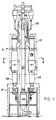
- FIGURE 1 is an elevational view of the overall system of the present invention;
- FIGURE 2 is an enlarged sectional elevational view of the reactor and cracked gas-solids separator of the present invention;
- FIGURE 3 is a sectional elevational view through line 3-3 of FIGURE 2;
- FIGURE 4 is a plan view through line 4-4 of FIGURE 2.
- FIGURE 5 is a sectional plan view through line 5-5 of FIGURE 2;
- FIGURE 6 is a partial view of the solids inlet to the reactor shown in FIGURE 5;
- FIGURE 7 is a sectional plan view through line 7-7 of FIGURE 2;
- FIGURE 8 is a sectional view through line 8-8 of FIGURE 1; and
- FIGURE 9 is a schematic elevational view of the solids regeneration assembly.
- The process and apparatus of the present invention have application in the various cracking environments, in which solids are used whether the solids be inert or catalytic. However, the process and apparatus of the present invention will be described with reference to a catalytic cracking process for producing olefins from hydrocarbon feed.
- As best seen in FIGURE 1, the
system 2 is comprised essentially ofreactor system 4, asolids regeneration assembly 8 and asolids delivery system 10. - The
reactor system 4, best seen in FIGURE 2, includes of a convergent mixing section 11, anelongated reaction section 12, adivergent section 13 downstream of theelongated reaction section 12, aseparator 6 and quench system 7 (shown in FIGURE 7). The mixing sections 11 are formed with aplug section 14 shown in cross-section as having an arcuatelower surface 15. A horizontally disposedplate 17 is arranged over theplug section 14 in spaced-relationship with theplug section 14 to formsolids inlet passages 19 to the interior of the mixing section 11. Thesolids inlet passages 19 are configured in cross-section with a right angle turn and terminate inrectangular openings 25 through which the particulate solids enter the mixing section 11, in the form a curtain ofsolids 26 as best seen in FIGURE 3. Thehorizontal openings 25 are directly above each hydrocarbon feed inlet. Venturi configured passages 3 extend from thesolids inlet passages 19 to thehydrocarbon feed inlets 28. -
Steam plenums 21, best seen in FIGURES 5 and 6, are arranged along each longitudinal edge of thehorizontal opening 25 to deliver pre-acceleration gas (steam) throughnozzles 29 into the curtain ofsolids 26 passing through thehorizontal openings 25. Agas delivery line 27 is provided to deliver gas, usually steam or light hydrocarbon, under pressure to thenozzles 29. Thenozzles 29 are arranged at a downward angle of 45° to the horizontal. The pre-acceleration gas is delivered to theplenums 21 at pressures of 3 to 5 psi above the pressure in the reactor and discharges through thenozzles 29 at that same relative pressure at a velocity of about 150 feet per second. The pre-acceleration gas accelerates the flow of solids through thehorizontal openings 25 from a nominal three to six feet per second to approximately 50 feet per second for the mix of solids and pre-acceleration gas. - The
hydrocarbon feed inlets 28 are located on the reactor wall 22 arranged either normal to thesolids curtain 26 or at an angle upwardly of 30° into thesolids curtain 26. The hydrocarbon feed is delivered to a manifold 23 through aline 24. Thefeed inlet nozzles 28 are fed with hydrocarbon from the manifold 23. As seen in FIGURE 2, thefeed inlet nozzles 28 are diametrically opposed from each other in the same horizontal plane. The mixing zone 11 of the reactor is rectangular as seen in FIGURE 4 with the configuration making a transition to a tubular reactor at theelongated reaction section 12. - The feedstock entering the mixing zone 11 through
nozzles 28 immediately impinge thesolids curtains 26 and the desired mixing of feed and hot particulate solids occurs. With the opposing set ofnozzles 28, the opposing feed jets and entrained solids from thesolids curtain 26 will be directed by thearcuate contour 15 of theplug section 14 and impact with each other at approximately the vertical centerline of the mixing zone 11. When a gas-liquid mixed phase hydrocarbon is fed through thenozzles 28, thenozzles 28 are arranged at an angle normal or 90° to thesolids curtain 26. When the hydrocarbon feed is a gas, thenozzles 28 are arranged at an upwardly directed angle of 30° into the solids curtain. The quantity of solids entering the mixing zone 11 of the reaction system through thehorizontal inlets 19 is controlled in large part by the pressure differential between the mixing zone 11 of the reaction system and thechamber 21 above thesolids reservoir 18 in a solids control hopper 31 directly above thehorizontal inlets 19. Pressure probes 33 and 35 are located respectively in the mixing zone 11 of the reaction system and thecontrol hopper chamber 21 to measure the pressure differential. Gas (steam) under pressure is delivered through aline 30 to thecontrol hopper chamber 21 to regulate the pressure differential between the mixing zone 11 of the reaction system and thecontrol hopper chamber 21 to promote or interrupt flow of the solids from the solids control hopper 31 to the mixing zone 11 of the reaction system. A detailed description of the process of regulating the solids flow is found in United States Patents No. 4,459,071 and 4,453,865 that are incorporated herein by reference. - The hydrocarbon feed enters the mixing zone 11 of the reaction system at a temperature of 200 to 1100°F and is elevated to a cracking temperature of 1000 to 1500°F. Cracking proceeds through the mixing zone 11 and elongated cracking
zone 12. Thereafter, the combined cracked effluent and entrained particulate solids discharge to theseparator 6. The residence time from the hydrocarbon entry into the reaction system to entry into theseparator 6 of the reaction system is 0.05 to 0.5 seconds. This time represents the time of intimate contact between catalyst and hydrocarbon. - As best seen in FIGURE 2, the
separator 6 is comprised of a mixed phase inlet 32, ahorizontal chamber section 34, a plurality of crackedgas outlets 36 andparticulate solids outlets 38. Theseparator 6 is an improvement on the solids-gas separator described in United States Patent No. 4,433,984, the subject matter of which is incorporated herein by reference. The basic principles relating to relative diameters (Di, Dog, Dos), chamber height (H) and length (L) recited in United States Patent No. 4,433,984 again obtain. However, theseparator 6 is arranged in combination with the elongated crackingzone 12 anddivergent section 13 of the reaction system. Thedivergent section 13 of the reaction system terminates in the separator mixed phase inlet 32 which is centrally disposed at the top of thehorizontal section 34. As a result of the configuration of the composite reaction system including theseparator 6, asolids bed 42 develops on the floor 40 of thehorizontal section 34 with thecross-sectional profile 43 of thebed 42 forming a curvilinear arc over which the mixed phase gas and solids travel. The expansion of solids and cracked gas in thedivergent section 13 enhances heat transfer and limits the velocity of the solids-gas mixture entering theseparator 6. - The solids are sent to the lateral ends 46 of the
horizontal section 34 and discharge downwardly through thesolids outlets 38. The cracked gases follow a 180° path and after separation from the solids discharge throughgas outlets 36 that are located on the top of thehorizontal section 34 intermediate the lateral ends 46. The plurality ofsolids outlets 38 andgas outlets 36 provide simultaneously for both minimum time in the separation zone and maximum solids-gas separation. - The separation system also includes a
conventional cyclone separator 50 directly downstream of eachgas outlet 36, best seen in FIGURE 7. Theentry line 54 to eachcyclone separator 50 is arranged at an angle of 90° to thegas outlet 36 with thecyclone separators 50 vertically disposed in the system. The cyclone separators 50 serve to collect the remaining entrained particulate solids from the cracked gas discharged from theseparator 6. Adipleg line 49, returns the particulate solids to theregeneration assembly 8 and the cracked gas is sent for downstream processing through thegas outlet 51. - In practice, the
separator 6 separates 95 to 99% of the solids from a gas solids mixtures having dust loadings of 0.2 to 0.3 pounds of solid per cubic foot of gas where the average particle size of the solids is 90 microns. - Each
cyclone entry line 54 extending from the crackedgas outlet 36 to thecyclone 50 is provided with a direct quenchline 52. Quench oil, usually the 100-400°F cut from a downstream distillation tower is introduced into thecyclone 50 through the direct quenchline 52 to terminate the reactions of the cracked gas. 0.1 to 0.3 gallons of quench oil are introduced upstream of thecyclone 50 for every pound of cracked gas. - In practice, it has been found that the cracking time; i.e. effective kinetic residence time is the time that elapses from the introduction of feed into the reaction system until the termination of cracked gas reactions in the
cyclone 50. The effective kinetic residence time includes the time during which the hydrocarbon and catalyst are in intimate contact and the time from separation until quench. This effective kinetic residence time is 0.1 to 0.6 seconds. - As best seen in FIGURE 9, the
regeneration assembly 8 is comprised of astripper 53,control hopper 55, entrainedbed heater 58, alift line 57, and a regeneratedsolids vessel 60. - The
stripper 53 is a tubular vessel into which the particulate solids from theseparator 6 are delivered through solids outlet legs extending from theseparator solids outlets 38 and from the cyclone diplegs 49. Aring 62 best seen in FIGURE 9, havingnozzle openings 64 is provided at the bottom of thestripper 53. A stripping gas, typically steam, is delivered to thering 62 for discharge through thenozzles 64. The stripping steam passes upwardly through the bed of particulate solids to remove impurities from the surface of the particulate solids. 1.0 to 3.0 pounds of steam at 200°F to 500°F temperature and 20 to 200 psig pressure are delivered to the stripper for each 0.5 ton of particulate solids. The stripping steam and entrained impurities pass upwardly through the particulate solids in thestripper 53 and discharge through a vent line (not shown) to the cracked gas line. - The stripped solids are accumulated in the
control hopper 55 for eventual delivery to the entrainedbed heater 58. Thecontrol hopper 55 is a collection vessel in which solids enter through thestandpipe 66 and from which anoutlet line 73 extends to deliver solids to the entrainedbed heater 58. The assembly of thecontrol hopper 55 andstandpipe 66 provides for a slumped bed solids transport system as described in United States Patents Nos. 4,459,071 and 4,453,865, which are incorporated herein by reference. The pressure differential maintained between the slumpedbed surface 68 in thecontrol hopper 55 and theexit 70 of theoutlet line 73 determine the solids flow rate between thecontrol hopper 55 and the entrainedbed heater 58. A line 72 is provided to selectively introduce steam under pressure into thecontrol hopper 55 to regulate the pressure differential.Probes control hopper 55 and entrainedbed heater 58 to monitor the pressure differential and regulate thevalve 65 in the steam line 72. - The entrained
bed heater 58 is essentially tubular in configuration. An array ofdistinct fuel nozzles 61 fed byfuel lines 63 are arranged essentially symmetrically on the lowerinclined surface 75 of the entrainedbed heater 58. Air under pressure enters the entrainedbed heater 58 through anozzle 77 arranged to direct the air axially upwardly through the entrainedbed heater 58. The air jet provides both the motive force to lift the solids particles upwardly through the entrainedbed heater 58 to the regeneratedsolids vessel 60 and the air necessary for combustion. The fuel is ignited by contact with the hot solids in the presence of air. - The combustion gas/solids mixture moving upwardly through
lift line 57 enters the regeneratedsolids vessel 60 tangentially, preferably, perpendicular to the lift line to separate the combustion gases from the solids. As shown in FIGURE 1, thevessel 60 has adistube 85 in thegas outlet nozzle 86 to provide cyclonic movement which improves the separation efficiency of the system. - In operation, the solids slide down the inside edge of the entrained
bed heater 58 and are picked up by the central air jet which operates at a velocity of 80 to 150 feet per second. The superficial velocity in the main body of the entrainedbed heater 58 is 8 to 15 feet per second. The reduction in velocity and the use of a single central jet creates a circulation in dilute phase within the expanded portion of the bed. The entrained solids fall to the side and are re-entrained in the jet. The velocities are such that there is a net transport of solids up thelift line 57 with the wide spot in the line creating a zone of recirculation and hence higher solid density and residence time. Practice shows that the solids on the average recirculate about 10 to 15 times compared to the net throughput. The characteristics and advantages of the entrainedbed heater 58 include a recirculation system that creates a higher solids density that minimizes peak temperatures that could damage catalysts or solid. In addition, the combustion in the entrainedbed heater 58 occurs in the gas phase. The solids are suspended in the gas and thus the combustion is rapid and the gas and fuel are intimately mixed in the combustion zone. - The combustion reaction in the entrained bed heater includes the coke coating the particulate solids. Thus, the feed to air ratio is maintained for a nominal 10% excess of air over fuel and insures that all the coke on the particulate solids is burned and contributes to the solids heating process. The reaction is of a type similar to
CHx + O₂ H₂O + CO₂.
- The regenerated
solids vessel 60 is a cylindrical vessel provided with a standpipe 71, seen in FIGURE 2, extending to the reactor hopper 31. Again the structure of the regeneratedsolids vessel 60 provides for accumulation of a slumpedbed 81, seen in FIGURE 9 above which pressure can be regulated to enable controlled delivery of the regenerated particulate solids to the reactor hopper 31. - The upper
solids collection vessel 60 seen in FIGURES 1, 2 and 9 contains a stripping section as the lower portion with a strippingring 79 and forms a part of the solids deliversystem 10. Abovering 79, the solids are fluidized; below thering 79 the solids slump and are fed to the standpipe 71. The standpipe 71 feeds the slumped bed in the control hopper 31 as best seen in FIGURE 2. Solids flow into the reactor hopper 31 through the standpipe 71 to replace solids that have flowed into thereactor 4. Unearated solids (slumped solids) will not continue to flow into the reactor hopper 31 once the entrance 82 to the hopper 31 has been covered. Thus the position of the entry 82 defines the solids level in hopper 31. As solids flow from hopper 31 via pressure differential between the vapor space in thechamber 21 above thebed 18 and the mixture zone 11, the entry 82 is uncovered allowing additional solids to flow into the hopper 31. - The solids flow from the rectangular orifices or
solids inlet passages 19 is what can be described as extrusion flow. The solids are in dense phase until picked up by the pre-acceleration gas. A pressure drop of 0.5 to 5.0 psi is used to control the rate of solids flow to the reactor mixing section 11. - The process of the invention proceeds by delivering pre-acceleration gas feed such as steam at a temperature of 400 to 1100°F through the pre-acceleration inlets and hydrocarbon feed at a temperature of 300 to 1100°F such as, LPG, naphtha, gas oil, or resid through the
feed nozzles 28 to thereactor 4. The hot particulate solids are delivered to thereactor 4 through the rectangular orifices at a temperature of 1200 to 1700°F. The hydrocarbon feed mixes with the hot particulate solids and is cracked at a cracking temperature of 1100 to 1500°F. The pressure in the reactor is 6 to 60 psi and the residence time or contact time from hydrocarbon feed entry to quenched cracked gas effluent is 0.1 to 0.6 seconds. The hot particulate solids are cooled from a temperature of 1200 to 1700°F to 1100 to 1500°F and spend 0.1 to 0.6 seconds from passage through the rectangular orifice to discharge from the separator solids outlet. - The cracked gases are quenched by direct quench oil in the cyclone to 1000 to 1200°F degrees. Thereafter, additional quench cooling is performed to reduce the cracked effluent temperature to 300 to 700°F. for fractionation.
- The solids are stripped of surface impurities in the stripper by steam at temperatures of 1100 to 1500°F. The stripped particulate solids are then delivered to the entrained bed heater at a temperature of 1100 to 1500°F. Fuel having a BTU content of 17,000-22,000 BTU/LB and 12 to 17 pounds of air per pound of fuel and coke are continuously fed to the entrained bed heater and combusted with the coke (carbon) on the particulate solids at temperatures of 1200 to 1700°F and a pressure of 6 to 60 psi. Hot particulate solids are delivered to the regenerated solids vessel at a temperature of 1200 to 1700°F where the combustion gases are separated in the separator and cyclones and exhausted as flue gas. The flue gas has no BTU content and is used to preheat feedstock or generate steam.
- The hot solids are returned to the
reactor 4 through the reactor hopper and rectangular orifices at a temperature of 1200 to 1500°F. - A projected material balance is as follows:
-naphtha feed 50,000 lb/hr secondary feed only
-dilution steam 1600 lb/hr 3000 lb/hr primary 13000 lb/hr secondary
-solid circulation 850,000 lb/hr
-naphtha preheat temp 900°F
-dilution steam preheat temp 1100°F
-reactor outlet temperature 1340°F
-solid inlet temperature 1590°F
-air flow 75000 lb/hr preheated to 700°F (by flue gas)
-fuel required
coke on solid from reaction 250 lb/hr (3.9 MMBTU/hr) external fuel 4670 lb/hr (77 MMBTU/hr) - In practice it has been found that the particulate solids loss is 0.005% of circulation in the practice of the present invention.
- The yield from the 50,000 lb/hr of naphtha is as follows:
Product Yield (Weight %) H2 0.67 CH4 13.05 C2H2 0.39 C2H4 27.47 C2H6 3.52 C3H4 0.51 C3H6 15.01 C3H8 0.49 C4H6 3.82 O-C4's 4.58 C5's 5.08 Benzene 5.09 Toulene 3.98 EB+X 3.17 Styrene 1.02 O-C6 2.05 O-C7 2.45 O-C8 1.34 C9-400°F 2.72 LFO 3.05 HFO 0.05 Coke 0.49
Claims (33)
Applications Claiming Priority (2)
| Application Number | Priority Date | Filing Date | Title |
|---|---|---|---|
| US07/084,328 US4814067A (en) | 1987-08-11 | 1987-08-11 | Particulate solids cracking apparatus and process |
| US84328 | 1987-08-11 |
Publications (2)
| Publication Number | Publication Date |
|---|---|
| EP0303302A1 true EP0303302A1 (en) | 1989-02-15 |
| EP0303302B1 EP0303302B1 (en) | 1992-07-29 |
Family
ID=22184263
Family Applications (1)
| Application Number | Title | Priority Date | Filing Date |
|---|---|---|---|
| EP88200856A Expired - Lifetime EP0303302B1 (en) | 1987-08-11 | 1988-05-03 | Particulate solids cracking apparatus and process |
Country Status (13)
| Country | Link |
|---|---|
| US (3) | US4814067A (en) |
| EP (1) | EP0303302B1 (en) |
| JP (1) | JPS6462389A (en) |
| KR (1) | KR910004940B1 (en) |
| CN (1) | CN1014067B (en) |
| BR (1) | BR8801976A (en) |
| CA (1) | CA1300069C (en) |
| DE (1) | DE3873211T2 (en) |
| ES (1) | ES2033415T3 (en) |
| FI (1) | FI94771C (en) |
| IN (1) | IN170086B (en) |
| MX (1) | MX164393B (en) |
| NO (1) | NO172292C (en) |
Families Citing this family (44)
| Publication number | Priority date | Publication date | Assignee | Title |
|---|---|---|---|---|
| US5098672A (en) * | 1987-08-11 | 1992-03-24 | Stone & Webster Engineering Corp. | Particulate solids cracking apparatus and process |
| US5391289A (en) * | 1990-09-04 | 1995-02-21 | Chevron Research And Technology Company | FCC process with rapid separation of products |
| US5254788A (en) * | 1991-09-10 | 1993-10-19 | Stone And Webster Engineering Corporation | Process for the production of olefins from light paraffins |
| US5435906A (en) * | 1992-08-20 | 1995-07-25 | Stone & Webster Engineering Corporation | Process for catalytically cracking feedstocks paraffin rich comprising high and low concarbon components |
| CN1089641A (en) * | 1992-08-20 | 1994-07-20 | 史东及韦伯斯特工程公司 | The catalyst cracking method that contains the paraffin-rich feedstock of high and low Kang Laxun carbon residue component |
| US5328591A (en) * | 1992-10-13 | 1994-07-12 | Mobil Oil Corporation | Mechanical shattering of asphaltenes in FCC riser |
| US5462652A (en) * | 1993-09-24 | 1995-10-31 | Uop | Short contact FCC process with catalyst blending |
| US5723040A (en) * | 1994-09-22 | 1998-03-03 | Stone & Webster Engineering Corporation | Fluid catalytic cracking process and apparatus |
| US5662868A (en) * | 1994-09-22 | 1997-09-02 | Stone & Webster Engineering Corporation | Short residence time cracking apparatus and process |
| US6552240B1 (en) | 1997-07-03 | 2003-04-22 | Exxonmobil Chemical Patents Inc. | Method for converting oxygenates to olefins |
| US6346219B1 (en) * | 1998-11-20 | 2002-02-12 | Uop Llc | FCC feed injector with closure plug |
| US8105482B1 (en) | 1999-04-07 | 2012-01-31 | Ivanhoe Energy, Inc. | Rapid thermal processing of heavy hydrocarbon feedstocks |
| FR2795022A1 (en) * | 1999-06-21 | 2000-12-22 | Michelin Soc Tech | Assembly has pneumatic tyre whose beads are connected by two deformable adapters to rim no more than half width of fully inflated tyre |
| FR2802211B1 (en) * | 1999-12-14 | 2002-02-01 | Inst Francais Du Petrole | CATALYTIC CRACKING PROCESS AND DEVICE INCLUDING PARALLEL AT LEAST ONE ASCENDING FLOW REACTOR AND AT LEAST ONE DESCENDING FLOW REACTOR |
| US6743747B1 (en) | 2000-02-24 | 2004-06-01 | Exxonmobil Chemical Patents Inc. | Catalyst pretreatment in an oxgenate to olefins reaction system |
| US6339182B1 (en) | 2000-06-20 | 2002-01-15 | Chevron U.S.A. Inc. | Separation of olefins from paraffins using ionic liquid solutions |
| US6660812B2 (en) | 2000-07-13 | 2003-12-09 | Exxonmobil Chemical Patents Inc. | Production of olefin derivatives |
| DK1332199T3 (en) * | 2000-09-18 | 2012-02-06 | Ivanhoe Htl Petroleum Ltd | Products made by rapid thermal treatment of heavy hydrocarbon raw materials |
| US8062503B2 (en) * | 2001-09-18 | 2011-11-22 | Ivanhoe Energy Inc. | Products produced from rapid thermal processing of heavy hydrocarbon feedstocks |
| US6875899B2 (en) * | 2001-02-01 | 2005-04-05 | Exxonmobil Chemical Patents Inc. | Production of higher olefins |
| US20020103406A1 (en) | 2001-02-01 | 2002-08-01 | Georges Mathys | Production of olefin dimers and oligomers |
| US6441262B1 (en) | 2001-02-16 | 2002-08-27 | Exxonmobil Chemical Patents, Inc. | Method for converting an oxygenate feed to an olefin product |
| US6518475B2 (en) | 2001-02-16 | 2003-02-11 | Exxonmobil Chemical Patents Inc. | Process for making ethylene and propylene |
| US6849774B2 (en) * | 2001-12-31 | 2005-02-01 | Chevron U.S.A. Inc. | Separation of dienes from olefins using ionic liquids |
| US20030127358A1 (en) * | 2002-01-10 | 2003-07-10 | Letzsch Warren S. | Deep catalytic cracking process |
| US20030147604A1 (en) * | 2002-02-01 | 2003-08-07 | Tapia Alejandro L. | Housing assembly for providing combined electrical grounding and fiber distribution of a fiber optic cable |
| US7572362B2 (en) * | 2002-10-11 | 2009-08-11 | Ivanhoe Energy, Inc. | Modified thermal processing of heavy hydrocarbon feedstocks |
| US7572365B2 (en) * | 2002-10-11 | 2009-08-11 | Ivanhoe Energy, Inc. | Modified thermal processing of heavy hydrocarbon feedstocks |
| US7128827B2 (en) * | 2004-01-14 | 2006-10-31 | Kellogg Brown & Root Llc | Integrated catalytic cracking and steam pyrolysis process for olefins |
| US7067597B2 (en) * | 2004-02-25 | 2006-06-27 | Exxonmobil Chemical Patents Inc. | Process of making polypropylene from intermediate grade propylene |
| US7199277B2 (en) * | 2004-07-01 | 2007-04-03 | Exxonmobil Chemical Patents Inc. | Pretreating a catalyst containing molecular sieve and active metal oxide |
| US7381320B2 (en) * | 2004-08-30 | 2008-06-03 | Kellogg Brown & Root Llc | Heavy oil and bitumen upgrading |
| US8129576B2 (en) * | 2005-06-30 | 2012-03-06 | Uop Llc | Protection of solid acid catalysts from damage by volatile species |
| US20080011644A1 (en) * | 2006-07-13 | 2008-01-17 | Dean Christopher F | Ancillary cracking of heavy oils in conjuction with FCC unit operations |
| US20080011645A1 (en) * | 2006-07-13 | 2008-01-17 | Dean Christopher F | Ancillary cracking of paraffinic naphtha in conjuction with FCC unit operations |
| US7491315B2 (en) * | 2006-08-11 | 2009-02-17 | Kellogg Brown & Root Llc | Dual riser FCC reactor process with light and mixed light/heavy feeds |
| US7820034B2 (en) | 2006-10-09 | 2010-10-26 | Kellogg Brown & Root Llc | Diluent from heavy oil upgrading |
| CA2762093A1 (en) * | 2009-04-15 | 2010-10-21 | Marathon Oil Canada Corporation | Nozzle reactor and method of use |
| US8309776B2 (en) * | 2009-12-15 | 2012-11-13 | Stone & Webster Process Technology, Inc. | Method for contaminants removal in the olefin production process |
| KR101954472B1 (en) | 2011-07-27 | 2019-03-05 | 사우디 아라비안 오일 컴퍼니 | Fluidized catalytic cracking of paraffinic naphtha in a downflow reactor |
| TR201901976T4 (en) | 2012-03-27 | 2019-03-21 | Indian Oil Corp Ltd | A device and a method for liquid catalytic cracking. |
| US9707532B1 (en) | 2013-03-04 | 2017-07-18 | Ivanhoe Htl Petroleum Ltd. | HTL reactor geometry |
| WO2017081595A1 (en) | 2015-11-12 | 2017-05-18 | Sabic Global Technologies B.V. | Methods for producing aromatics and olefins |
| CN113447403B (en) * | 2021-06-11 | 2022-05-03 | 南京航空航天大学 | Heating device for measuring spectral emissivity of high-temperature particle curtain |
Citations (5)
| Publication number | Priority date | Publication date | Assignee | Title |
|---|---|---|---|---|
| DE1036217B (en) * | 1955-01-31 | 1958-08-14 | Bataafsche Petroleum | Method and device for achieving a rapid change in temperature of gases or liquids |
| US3120485A (en) * | 1961-01-18 | 1964-02-04 | Air Prod & Chem | Method and apparatus for contacting liquid with granular contact material |
| EP0026674A2 (en) * | 1979-10-02 | 1981-04-08 | Stone & Webster Engineering Corporation | Improvements in thermal regenerative cracking apparatus and process |
| EP0150239A1 (en) * | 1982-04-16 | 1985-08-07 | Engelhard Corporation | Process and apparatus for upgrading crude oil and residual fractions thereof |
| EP0226483A1 (en) * | 1985-11-12 | 1987-06-24 | Institut Français du Pétrole | Process and apparatus for the catalytic cracking of a hydrocarbon feedstock submitted to a pretreatment with solid particles having a poor activity |
Family Cites Families (24)
| Publication number | Priority date | Publication date | Assignee | Title |
|---|---|---|---|---|
| US2548912A (en) * | 1951-04-17 | Process of and apparatus for con | ||
| US2906695A (en) * | 1956-08-07 | 1959-09-29 | Exxon Research Engineering Co | High temperature short time hydrocarbon conversion process |
| US2937988A (en) * | 1957-03-19 | 1960-05-24 | Exxon Research Engineering Co | Prevention of coking on walls of transfer line reactor |
| BE601348A (en) * | 1960-03-16 | |||
| US3676519A (en) * | 1970-01-02 | 1972-07-11 | Lummus Co | Quench process |
| US3663645A (en) * | 1970-02-02 | 1972-05-16 | Lummus Co | Liquid quench |
| US4288235A (en) * | 1979-07-06 | 1981-09-08 | Stone & Webster Engineering Corporation | Low residence time solid-gas separation device and system |
| US4433984A (en) * | 1979-07-06 | 1984-02-28 | Stone & Webster Engineering Corp. | Low residence time solid-gas separation device and system |
| US4338187A (en) * | 1979-10-22 | 1982-07-06 | Stone & Webster Engineering Corporation | Solids feeding device and system |
| US4318800A (en) * | 1980-07-03 | 1982-03-09 | Stone & Webster Engineering Corp. | Thermal regenerative cracking (TRC) process |
| US4356151A (en) * | 1979-10-05 | 1982-10-26 | Stone & Webster Engineering Corp. | Solids quench boiler |
| US4419221A (en) * | 1981-10-27 | 1983-12-06 | Texaco Inc. | Cracking with short contact time and high temperatures |
| US4459071A (en) * | 1982-01-25 | 1984-07-10 | Stone & Webster Engineering Corp. | Solids flow regulator |
| FR2520354A1 (en) * | 1982-01-27 | 1983-07-29 | Inst Francais Du Petrole | PROCESS FOR THE METHANIZATION OF SOLID CARBON MATERIALS |
| US4453865A (en) * | 1982-07-21 | 1984-06-12 | Stone & Webster Engineering Corp. | Automatic pressure sensitive regulation assembly |
| US4404095A (en) * | 1982-07-22 | 1983-09-13 | Mobil Oil Corporation | Method and means for separating gaseous materials from finely divided catalyst particles |
| US4495060A (en) * | 1982-12-27 | 1985-01-22 | Hri, Inc. | Quenching hydrocarbon effluent from catalytic reactor to avoid precipitation of asphaltene compounds |
| US4534851A (en) * | 1983-06-02 | 1985-08-13 | Exxon Research And Engineering Co. | Feed injection method to prevent coking on the walls of transfer line reactors |
| US4552645A (en) * | 1984-03-09 | 1985-11-12 | Stone & Webster Engineering Corporation | Process for cracking heavy hydrocarbon to produce olefins and liquid hydrocarbon fuels |
| US4578183A (en) * | 1984-11-30 | 1986-03-25 | Mobil Oil Corporation | Feed mixing technique for fluidized catalytic cracking of hydrocarbon oil |
| US4764268A (en) * | 1987-04-27 | 1988-08-16 | Texaco Inc. | Fluid catalytic cracking of vacuum gas oil with a refractory fluid quench |
| US4925632A (en) * | 1988-01-29 | 1990-05-15 | Thacker Milton B | Low profile fluid catalytic cracking apparatus |
| US4902407A (en) * | 1988-06-09 | 1990-02-20 | Texaco Inc. | Catalyst inventory control in an ebullated bed process |
| US5087427A (en) * | 1990-03-26 | 1992-02-11 | Amoco Corporation | Catalytic cracking unit with internal gross cut separator and quench injector |
-
1987
- 1987-08-11 US US07/084,328 patent/US4814067A/en not_active Expired - Lifetime
-
1988
- 1988-03-17 IN IN226/CAL/88A patent/IN170086B/en unknown
- 1988-04-14 FI FI881748A patent/FI94771C/en not_active IP Right Cessation
- 1988-04-14 JP JP63092638A patent/JPS6462389A/en active Granted
- 1988-04-20 MX MX11183A patent/MX164393B/en unknown
- 1988-04-25 BR BR8801976A patent/BR8801976A/en not_active Application Discontinuation
- 1988-05-03 ES ES198888200856T patent/ES2033415T3/en not_active Expired - Lifetime
- 1988-05-03 EP EP88200856A patent/EP0303302B1/en not_active Expired - Lifetime
- 1988-05-03 DE DE8888200856T patent/DE3873211T2/en not_active Expired - Lifetime
- 1988-05-10 CN CN88102644A patent/CN1014067B/en not_active Expired
- 1988-06-02 KR KR1019880006597A patent/KR910004940B1/en not_active Expired
- 1988-08-10 NO NO883551A patent/NO172292C/en unknown
- 1988-08-11 CA CA000574479A patent/CA1300069C/en not_active Expired - Fee Related
-
1993
- 1993-02-10 US US08/016,060 patent/US5340545A/en not_active Expired - Fee Related
- 1993-02-11 US US08/016,766 patent/US5324484A/en not_active Expired - Lifetime
Patent Citations (5)
| Publication number | Priority date | Publication date | Assignee | Title |
|---|---|---|---|---|
| DE1036217B (en) * | 1955-01-31 | 1958-08-14 | Bataafsche Petroleum | Method and device for achieving a rapid change in temperature of gases or liquids |
| US3120485A (en) * | 1961-01-18 | 1964-02-04 | Air Prod & Chem | Method and apparatus for contacting liquid with granular contact material |
| EP0026674A2 (en) * | 1979-10-02 | 1981-04-08 | Stone & Webster Engineering Corporation | Improvements in thermal regenerative cracking apparatus and process |
| EP0150239A1 (en) * | 1982-04-16 | 1985-08-07 | Engelhard Corporation | Process and apparatus for upgrading crude oil and residual fractions thereof |
| EP0226483A1 (en) * | 1985-11-12 | 1987-06-24 | Institut Français du Pétrole | Process and apparatus for the catalytic cracking of a hydrocarbon feedstock submitted to a pretreatment with solid particles having a poor activity |
Also Published As
| Publication number | Publication date |
|---|---|
| KR910004940B1 (en) | 1991-07-18 |
| IN170086B (en) | 1992-02-08 |
| US4814067A (en) | 1989-03-21 |
| DE3873211T2 (en) | 1992-12-10 |
| CA1300069C (en) | 1992-05-05 |
| EP0303302B1 (en) | 1992-07-29 |
| US5340545A (en) | 1994-08-23 |
| FI881748A7 (en) | 1989-02-12 |
| FI94771B (en) | 1995-07-14 |
| BR8801976A (en) | 1989-02-21 |
| NO883551L (en) | 1989-02-13 |
| ES2033415T3 (en) | 1993-03-16 |
| NO172292B (en) | 1993-03-22 |
| NO172292C (en) | 1993-06-30 |
| MX164393B (en) | 1992-08-11 |
| CN1031245A (en) | 1989-02-22 |
| KR890003923A (en) | 1989-04-18 |
| FI881748A0 (en) | 1988-04-14 |
| US5324484A (en) | 1994-06-28 |
| FI94771C (en) | 1995-10-25 |
| JPH051836B2 (en) | 1993-01-11 |
| JPS6462389A (en) | 1989-03-08 |
| NO883551D0 (en) | 1988-08-10 |
| CN1014067B (en) | 1991-09-25 |
| DE3873211D1 (en) | 1992-09-03 |
Similar Documents
| Publication | Publication Date | Title |
|---|---|---|
| US4814067A (en) | Particulate solids cracking apparatus and process | |
| US4919898A (en) | Particulate solids cracking apparatus | |
| US7799287B2 (en) | Apparatus and process for regenerating catalyst | |
| EP0086580B1 (en) | Method and apparatus for fluid catalytic cracking | |
| EP0151882B1 (en) | Method and apparatus for injecting liquid hydrocarbon feed steam into a catalytic cracking zone | |
| US5087349A (en) | Process for selectively maximizing product production in fluidized catalytic cracking of hydrocarbons | |
| US5582712A (en) | Downflow FCC reaction arrangement with upflow regeneration | |
| EP0254333A1 (en) | Downflow fluidized catalytic cracking reactor and process | |
| EP0490886A2 (en) | Process for selectively producing ethylene and aromatics by catalytic cracking | |
| US5104517A (en) | Vented riser apparatus and method | |
| CA1258440A (en) | Catalytic cracking unit and operation | |
| CA1311437C (en) | Process of thermally cracking hydrocarbons using particulate solids as heat carrier | |
| EP0369536A1 (en) | Process for selectively maximizing product production in fluidized catalytic cracking of hydrocarbons | |
| US4405444A (en) | Method and means for charging foamed residual oils in contact with fluid solid particulate material | |
| US3433733A (en) | Method and apparatus for fluid catalytic cracking | |
| EP2070592A2 (en) | Apparatus and process for regenerating catalyst | |
| US5098672A (en) | Particulate solids cracking apparatus and process | |
| US4800014A (en) | Catalytic cracking process | |
| US5106587A (en) | Particulate solids cracking apparatus | |
| US5449497A (en) | Plug flow vented riser | |
| US7902101B2 (en) | Process for regenerating catalyst | |
| EP0482055B1 (en) | Method and apparatus for contacting solid particles and fluid | |
| KR950008999B1 (en) | Fcc process and apparatus having a low volume dilute phase disengagement zone in the reaction vessel | |
| JPH05295370A (en) | Fluidized catalytic cracking process and apparatus having low-quantity dilution phase separation zone in reactor | |
| JPH055875B2 (en) |
Legal Events
| Date | Code | Title | Description |
|---|---|---|---|
| PUAI | Public reference made under article 153(3) epc to a published international application that has entered the european phase |
Free format text: ORIGINAL CODE: 0009012 |
|
| AK | Designated contracting states |
Kind code of ref document: A1 Designated state(s): DE ES FR GB IT NL SE |
|
| 17P | Request for examination filed |
Effective date: 19890602 |
|
| 17Q | First examination report despatched |
Effective date: 19900528 |
|
| GRAA | (expected) grant |
Free format text: ORIGINAL CODE: 0009210 |
|
| AK | Designated contracting states |
Kind code of ref document: B1 Designated state(s): DE ES FR GB IT NL SE |
|
| ITF | It: translation for a ep patent filed | ||
| REF | Corresponds to: |
Ref document number: 3873211 Country of ref document: DE Date of ref document: 19920903 |
|
| ET | Fr: translation filed | ||
| REG | Reference to a national code |
Ref country code: ES Ref legal event code: FG2A Ref document number: 2033415 Country of ref document: ES Kind code of ref document: T3 |
|
| PLBE | No opposition filed within time limit |
Free format text: ORIGINAL CODE: 0009261 |
|
| STAA | Information on the status of an ep patent application or granted ep patent |
Free format text: STATUS: NO OPPOSITION FILED WITHIN TIME LIMIT |
|
| 26N | No opposition filed | ||
| EAL | Se: european patent in force in sweden |
Ref document number: 88200856.8 |
|
| PGFP | Annual fee paid to national office [announced via postgrant information from national office to epo] |
Ref country code: SE Payment date: 19950411 Year of fee payment: 8 |
|
| PGFP | Annual fee paid to national office [announced via postgrant information from national office to epo] |
Ref country code: FR Payment date: 19950421 Year of fee payment: 8 |
|
| PGFP | Annual fee paid to national office [announced via postgrant information from national office to epo] |
Ref country code: GB Payment date: 19950424 Year of fee payment: 8 |
|
| PGFP | Annual fee paid to national office [announced via postgrant information from national office to epo] |
Ref country code: ES Payment date: 19950425 Year of fee payment: 8 |
|
| PGFP | Annual fee paid to national office [announced via postgrant information from national office to epo] |
Ref country code: DE Payment date: 19950524 Year of fee payment: 8 |
|
| PGFP | Annual fee paid to national office [announced via postgrant information from national office to epo] |
Ref country code: NL Payment date: 19950531 Year of fee payment: 8 |
|
| PG25 | Lapsed in a contracting state [announced via postgrant information from national office to epo] |
Ref country code: GB Effective date: 19960503 |
|
| PG25 | Lapsed in a contracting state [announced via postgrant information from national office to epo] |
Ref country code: SE Effective date: 19960504 Ref country code: ES Free format text: LAPSE BECAUSE OF NON-PAYMENT OF DUE FEES Effective date: 19960504 |
|
| PG25 | Lapsed in a contracting state [announced via postgrant information from national office to epo] |
Ref country code: NL Effective date: 19961201 |
|
| GBPC | Gb: european patent ceased through non-payment of renewal fee |
Effective date: 19960503 |
|
| PG25 | Lapsed in a contracting state [announced via postgrant information from national office to epo] |
Ref country code: FR Effective date: 19970131 |
|
| PG25 | Lapsed in a contracting state [announced via postgrant information from national office to epo] |
Ref country code: DE Effective date: 19970201 |
|
| EUG | Se: european patent has lapsed |
Ref document number: 88200856.8 |
|
| NLV4 | Nl: lapsed or anulled due to non-payment of the annual fee |
Effective date: 19961201 |
|
| REG | Reference to a national code |
Ref country code: FR Ref legal event code: ST |
|
| REG | Reference to a national code |
Ref country code: ES Ref legal event code: FD2A Effective date: 19990301 |
|
| PG25 | Lapsed in a contracting state [announced via postgrant information from national office to epo] |
Ref country code: IT Free format text: LAPSE BECAUSE OF NON-PAYMENT OF DUE FEES Effective date: 20050503 |