EP0302652B1 - Container filling system - Google Patents
Container filling system Download PDFInfo
- Publication number
- EP0302652B1 EP0302652B1 EP88306877A EP88306877A EP0302652B1 EP 0302652 B1 EP0302652 B1 EP 0302652B1 EP 88306877 A EP88306877 A EP 88306877A EP 88306877 A EP88306877 A EP 88306877A EP 0302652 B1 EP0302652 B1 EP 0302652B1
- Authority
- EP
- European Patent Office
- Prior art keywords
- container
- measuring
- discharge
- axis
- containers
- Prior art date
- Legal status (The legal status is an assumption and is not a legal conclusion. Google has not performed a legal analysis and makes no representation as to the accuracy of the status listed.)
- Expired - Lifetime
Links
- 239000000463 material Substances 0.000 claims description 34
- 238000012546 transfer Methods 0.000 claims description 33
- 239000000945 filler Substances 0.000 claims description 23
- 241000251468 Actinopterygii Species 0.000 description 57
- XLYOFNOQVPJJNP-UHFFFAOYSA-N water Substances O XLYOFNOQVPJJNP-UHFFFAOYSA-N 0.000 description 10
- 230000001360 synchronised effect Effects 0.000 description 7
- 230000006835 compression Effects 0.000 description 6
- 238000007906 compression Methods 0.000 description 6
- 230000000694 effects Effects 0.000 description 5
- 230000000712 assembly Effects 0.000 description 4
- 238000000429 assembly Methods 0.000 description 4
- 238000000034 method Methods 0.000 description 4
- 238000012545 processing Methods 0.000 description 4
- 230000001133 acceleration Effects 0.000 description 3
- 238000006073 displacement reaction Methods 0.000 description 3
- 238000004519 manufacturing process Methods 0.000 description 3
- 238000010276 construction Methods 0.000 description 2
- 230000007547 defect Effects 0.000 description 2
- 230000001934 delay Effects 0.000 description 2
- 235000013372 meat Nutrition 0.000 description 2
- 239000002994 raw material Substances 0.000 description 2
- 238000007789 sealing Methods 0.000 description 2
- 210000000988 bone and bone Anatomy 0.000 description 1
- 238000004891 communication Methods 0.000 description 1
- 230000001419 dependent effect Effects 0.000 description 1
- 238000009826 distribution Methods 0.000 description 1
- 239000012530 fluid Substances 0.000 description 1
- 230000005484 gravity Effects 0.000 description 1
- 231100000206 health hazard Toxicity 0.000 description 1
- 230000003993 interaction Effects 0.000 description 1
- 238000012423 maintenance Methods 0.000 description 1
- 238000004806 packaging method and process Methods 0.000 description 1
- 230000000284 resting effect Effects 0.000 description 1
- 238000003860 storage Methods 0.000 description 1
- 238000013519 translation Methods 0.000 description 1
Images




Classifications
-
- B—PERFORMING OPERATIONS; TRANSPORTING
- B65—CONVEYING; PACKING; STORING; HANDLING THIN OR FILAMENTARY MATERIAL
- B65B—MACHINES, APPARATUS OR DEVICES FOR, OR METHODS OF, PACKAGING ARTICLES OR MATERIALS; UNPACKING
- B65B25/00—Packaging other articles presenting special problems
- B65B25/06—Packaging slices or specially-shaped pieces of meat, cheese, or other plastic or tacky products
-
- B—PERFORMING OPERATIONS; TRANSPORTING
- B65—CONVEYING; PACKING; STORING; HANDLING THIN OR FILAMENTARY MATERIAL
- B65G—TRANSPORT OR STORAGE DEVICES, e.g. CONVEYORS FOR LOADING OR TIPPING, SHOP CONVEYOR SYSTEMS OR PNEUMATIC TUBE CONVEYORS
- B65G53/00—Conveying materials in bulk through troughs, pipes or tubes by floating the materials or by flow of gas, liquid or foam
- B65G53/30—Conveying materials in bulk through pipes or tubes by liquid pressure
-
- A—HUMAN NECESSITIES
- A22—BUTCHERING; MEAT TREATMENT; PROCESSING POULTRY OR FISH
- A22C—PROCESSING MEAT, POULTRY, OR FISH
- A22C25/00—Processing fish ; Curing of fish; Stunning of fish by electric current; Investigating fish by optical means
- A22C25/12—Arranging fish, e.g. according to the position of head and tail
-
- B—PERFORMING OPERATIONS; TRANSPORTING
- B65—CONVEYING; PACKING; STORING; HANDLING THIN OR FILAMENTARY MATERIAL
- B65B—MACHINES, APPARATUS OR DEVICES FOR, OR METHODS OF, PACKAGING ARTICLES OR MATERIALS; UNPACKING
- B65B25/00—Packaging other articles presenting special problems
- B65B25/06—Packaging slices or specially-shaped pieces of meat, cheese, or other plastic or tacky products
- B65B25/061—Packaging slices or specially-shaped pieces of meat, cheese, or other plastic or tacky products of fish
Definitions
- This invention relates generally to container filling systems and, more particularly, to systems for introducing controlled volumes of filler material into containers, according to the preamble of claim 1.
- the dispensed material may vary considerably in attractiveness from one container to the next.
- the orientation of the meat, or the direction of its grain may vary considerably throughout the can, failing to present the image of a substantially uniform, single piece of meat.
- the incidental presence of skin or bones around the flange of the can may prevent the can from being properly sealed.
- the resultant seam defect prevents a vacuum from being maintained within the can and will eventually contribute to the spoilage of the contents. Because of the health hazard presented by such spoilage, the production of even a small percentage of containers with seam defects is to be avoided.
- US-A-3,513,626 discloses a container filling system for introducing controlled volumes of filler material into containers, the system comprising the features included in the preamble of claim 1, viz.: measuring means rotatable about a primary axis and arranged to receive predetermined volumes of filler material; feeder means arranged to introduce filler material into said measuring means under pressure and along a first axis which is offset from said primary axis and defined with respect to said measuring means, and rotatable discharge means which is arranged to discharge predetermined volumes of filler material from said measuring means into product-receiving containers.
- the present invention provides a container filling system as disclosed in US-A-3,513,626, characterised in that a transfer means is arranged to transfer removable measuring containers containing predetermined volumes of filler material from said measuring means to said discharge means into alignment with said discharge means and with product-receiving containers, said discharge means being arranged to rotate, together with the measuring containers, about a secondary axis which is different from said primary axis and to discharge said predetermined volumes of filler material along a third axis defined by the aligned measuring containers, discharge means and product-receiving containers, said third axis being offset from said secondary axis and rotating with said discharge means and said measuring containers.
- system 10 can be used to dispense a variety of bulk filler materials into numerous types of containers.
- system 10 is used to dispense precisely controlled portions of butchered fish, having their heads, fins and entrails removed, into cans.
- the container filling system includes a number of subsystems.
- a material feed subsystem 12 (partially shown) receives a bulk supply of randomly aligned, butchered fish in water. Feed subsystem 12 then aligns or orients the fish under pressure, packs them, and removes the water to provide a source of aligned fish that is of substantially uniform density.
- measuring subsystem 14 which operates in a continuous rotational pattern, produces portions of closely controlled weight and volume from the fish supplied by feed subsystem 12. These measured portions of fish are then advanced to a transfer subsystem 16.
- Transfer subsystem 16 transfers the controlled portions of fish produced by measuring subsystem 14 to a discharge subsystem 18.
- the continuously rotating discharge subsystem 18 dispenses the precisely controlled portions of fish produced by measuring subsystem 14 into containers advanced through the discharge subsystem 18 by a container advance subsystem 20.
- a common synchronized drive subsystem 22 is provided.
- feed subsystem 12 includes a tilted hopper 24 designed to receive and temporarily store a supply of butchered fish 26, in water, that is sufficient to allow system 10 to continue operation for short periods, even without the receipt of additional fish 26 by hopper 24.
- the inclusion of water allows the fish 26 to be pumped under pressure directly from a butchering station into hopper 24.
- Hopper 24 has a base 28 that is preferably shaped like the frustum of a cone.
- the transfer of fish 26 into, and through, section 29 may be further assisted by the establishment of a pressure in the hopper 24 that is greater than that of the surrounding atmosphere and the maintenance of an adequate flow of water, both of which may be accomplished with the aid of inlet and outlet ports 31 and 32.
- the tapered base 28, elbow 30, and transfer section 29 are dimensioned to cooperatively orient the butchered fish 26 substantially longitudinally in transfer section 29. More particularly, fish 26 will be oriented such that their backbones are disposed substantially along the axis of section 29 as they travel through section 29.
- a dewatering station 37 follows section 35 to remove the water that has previously been used to transport butchered fish 26 in alignment through subsystem 12. As shown, station 37 includes a plurality of sections 39 that each have a cylindrical bore 41 extending therethrough. The various sections 39 are coupled end-to-end to define a continued passage for the butchered fish 26 received from section 35.
- each section 39 of the dewatering station 37 is provided with a plurality of circumferentially spaced-apart ports 43 that allow water to escape.
- a channel 45 is provided in each section 39, extending circumferentially around bore 41 and in fluid communication with the ports 43.
- Each channel 45 is connected via a coupler 47 to an individual line 49 of a water outlet system 51.
- the number of sections 39 and ports 43 can be varied to provide the desired dewatering characteristics.
- valves can be included in lines 49 to control the escape of water through the ports 43 of each section 39 in any manner desired.
- the diameter of the passage through station 37 is sufficiently small to maintain the butchered fish 26 received therein in substantial alignment.
- the aligned fish 26 traverse a short horizontal section 53 of tube, followed by a 90° elbow 55, and a short vertical section 57 of tube. As this point, the butchered fish 26 move downward into a second compression section 59.
- Compression section 59 is shaped like the frustum of a cone and is dimensioned to effect the desired compression of butchered fish 26. More particularly, section 59, in cooperation with the applied hopper pressure, is designed to compress the dewatered and aligned fish 26 sufficiently to produce a continuous, aligned pack of substantially uniform density for advance to the measuring subsystem 14.
- the outlet of the tapered compression section 59 is securely connected to a flexible transfer tube 36.
- the diameter of transfer tube 36 corresponds to that of the lower end of section 59.
- the connection between section 59 and tube 36 is provided by a collar 38 that provides a relatively fluid-tight seal. While the upper end 40 of tube 36 is fixed, as shown in FIGURE 4, the lower end 42 of tube 36, which is connected to the rotating measuring subsystem 14 by a standard sanitary couple 61, undergoes horizontal translation in a circular pattern.
- the measuring subsystem 14 includes a flat, roughly rectangular guide plate 48 that is supported for horizontal rotation about a vertical shaft 50.
- a cylindrical guide 56 passes through plate 48 adjacent one end and extends above and below plate 48.
- a counterweight 63 is attached to the other end of plate 48 for balanced operation.
- a sleeve 44 having an inner diameter corrsponding to that of tube 36, is received within guide 56 and extends slightly above guide 56 to provide the desired connection with tube 36 at couple 61. In this manner, a supply of butchered fish 26 that is substantially aligned and of substantially uniform density is made available to the rotating measuring subsystem 14 under the direction of guide 56.
- a measuring chamber 62 that is vertically aligned with guide 56 in a plane below plate 58 is advanced past edge 60 by a horizontal chamber guide wheel 64 rotating in synchronization with guide plate 48.
- Measuring container 62 is a substantially cylindrical ring having a boss 66 projecting radially about its lower surface.
- Measuring container 62 is dimensioned to define a volume that corresponds to a predetermined mass of fish 26 when packed fish 26 having a particular density are introduced into container 62.
- the container guide wheel 64 is rotatably secured to shaft 50 and includes a recess 68 at its perimeter that is dimensioned to receive measuring container 62 and engage boss 66.
- the guide wheel 64 is affixed to the same vertical shaft 50 as guide plate 48, with the guide wheel recess 68 aligned with the fish guide 56 on guide plate 48, the vertical alignment of the measuring container 62 and the fish guide 56 is ensured as the trailing edge 60 of knife plate 58 is passed.
- measuring container 62 rides on a base plate 70 that prevents the escape of packed fish 26 from the bottom of container 62 when packed fish 26 are introduced under pressure through guide 56. Similarly, because guide 56 and measuring container 62 are relatively closely spaced, the escape of packed fish 26 from the top of container 62 is substantially prevented.
- a series of circumferentially aligned ports 65 are included in base plate 70. As will be appreciated, with a vacuum applied to ports 65, fish 26 is more readily drawn into container 62.
- knife edge 72 of knife plate 58 is eventually reached. As shown, knife edge 72 is displaced at an angle with respect to the path of advance of guide 56 and measuring container 62 to cleanly sever the fish pack 26 between guide 56 and measuring container 62 . As a result, a portion 74 of longitudinally aligned fish 26 having a closely controlled weight is produced in measuring container 62.
- guide wheel 64 in cooperation with a guide rail 76.
- Guide rail 76 extends over an arc of approximately 270° and limits the radial movement of measuring container 62 as it is rotated through measuring subsystem 14 by guide wheel 64.
- guide rail 76 is designed to loosely engage the outer surface of the measuring container 62, including boss 66.
- guide rail 76 is horizontally secured to the base plate 70, which, along with vertical shaft 50 and knife plate 58, is supported by a measuring subsystem support structure 78.
- subsystem 16 includes a forward guide wheel 80 that cooperates with a forward guide surface 82 of a rail 83 to transfer measuring container 62 from measuring subsystem 14 to the discharge subsystem 18 after the desired portion 74 of fish 26 is produced in the container 62 .
- a further subsystem 16 also includes a return guide wheel 84 that cooperates with a return guide surface 86 formed on the opposite side of rail 83, to return measuring container 62 to measuring subsystem 14 after the portion 74 has been dispensed into a container by the discharge subsystem 18.
- the forward guide wheel 80 is a roughly circular plate, corresponding in dimension to wheel 64 and mounted for horizontal rotation about a vertical drive shaft 88.
- Guide wheel 80 includes a recess 90 that is designed to cooperatively engage the measuring container 62 and advance it along guide rail surface 82 as the guide wheel 80 is rotated.
- Guide rail surface 82 defines an arc of approximately 90° and guide rail 83 is secured to the same base plate 70 as the measuring subsystem guide rail 76.
- the interaction between the guide wheel 64 and guide rail 76 of measuring subsystem 14 and the transfer system guide wheel 80 and guide rail 83 is synchronized by providing the proper initial orientation of vertical shafts 50 and 88 and then rotating them at the same speed.
- measuring container 62 is advanced by guide wheel 64 to the end of guide rail 76, at which point the guide surface 82 of rail 83 initiates the guidance of measuring container 62 under the influence of guide wheel 80.
- the forward guide wheel 80 and guide rail surface 82 advance measuring container 62 from measuring subsystem 14 to the discharge system 18, which dispenses portion 74 into a container and returns container 62 to the return guide wheel 84 and guide rail surface 86.
- Return guide wheel 84 and guide rail surface 86 which form subsystem 16', are of substantially the same construction as, and provide a mirrored operation of, forward guide wheel 80 and guide rail surface 82. More particularly, wheel 84 and surface 86 cooperatively receive measuring container 62 as it exits the discharge subsystem 18 and transfer it in an arcuate path until control of container 62 is resumed by the measuring subsystem guide wheel 64 and guide rail 76.
- return guide wheel 84 is an approximately circular plate that includes a recess 92 constructed to receive the measuring container 62 .
- Wheel 84 is secured for horizontal rotation about a vertical shaft 94.
- the guide surface 86 of rail 83 defines an arc of approximately 90°.
- discharge subsystem 18 includes a discharge assembly 104 that receives empty product containers 114 and filled measuring containers in vertical alignment and discharges the portions 74 of fish into the product containers.
- the discharge assembly 104 is secured to a vertical shaft 102 by a hub 106 and, as a result, is horizontally rotatable.
- three arms 108 located approximately 120° apart, project radially from hub 106.
- a discharge station 110 At the end of each arm 108 is a discharge station 110, where the actual transfer of portion 74 from measuring container 62 to product container 114 occurs.
- Each discharge station 110 includes a horizontally disposed platform 112 for receiving and supporting a container 114.
- the container 114 is further supported by a horizontal container receiving plate 116 that is spaced slightly above platform 112 and that includes a semicircular recess for receiving and engaging a portion of the side of container 114.
- Plate 116 and a guide rail 120 that is disposed about discharge assembly 104 cooperatively retain the container 114 on platform 112 as the discharge assembly 104 is rotated about shaft 102.
- each receiving plate 122 is located above the corresponding container receiving plate 116 and is recessed and slotted to receive the measuring container 62 and support it via boss 66.
- the receiving plate 122 also cooperates with the guide rail 120, which extends vertically to the level of plate 122, to retain the measuring container 62 in vertical alignment with product container 114 as the discharge assembly 104 rotates about vertical shaft 102.
- a plunger tip 124 is secured to the lower end of a vertically aligned plunger arm 126 disposed above chamber 62.
- the plunger arm 126 is slidably received between upper and lower support brackets 128 and 130 that are spaced apart by a support arm 132 and fixed with respect to station 110.
- the vertical displacement of plunger arm 126 is controlled by upper and lower bearing plate assemblies 134 and 136 that are secured to plunger arm 126 a spaced-apart distance between the upper and lower support brackets 128 and 130.
- the projecting ends of bearing plate assemblies 134 and 136 are equipped with bearings 138 and 140, which cooperatively engage a cam 142 that controls the vertical displacements of assemblies 134 and 136 and, hence, plunger arm 126.
- Cam 142 is a continuous loop of material having a rectangular cross section and is supported around the discharge assembly 104 by a support structure 144.
- the vertical height of cam 142 with respect to, for example, the arms 108 of the discharge assembly 104 varies approximately sinusoidally over 360°. Given the cooperation of bearing plate assemblies 134 and 136 with the cam 142, it will be appreciated that as discharge assembly 104 rotates, the variation in the height of cam 142 over the arm 108 effects a corresponding displacement in the plunger tip 124.
- cam 142 As will be described in greater detail below, the orientation of cam 142 with respect to the discharge assembly 104 is such that the receipt of a filled measuring container 62 by a station 110 corresponds to a downward slope in cam 142, causing the plunger tip 124 to move downward and force the portion 74 of fish from container 62 into the container 114 below.
- the diameter and alignment of plunger tip 124, measuring container 62 and product container 114 are such that air is easily vented from container 114 as the portion of fish is inserted. More particularly, the plunger tip 124 is slightly smaller in diameter than container 114 and its axis is offset from the centre of the container 114 supported on platform 112.
- the discharge station 110 continues to rotate back toward the transfer subsystem 16 as container 114 is filled and eventually the cam 142 will exhibit an upward slope causing the plunger tip 124 to be withdrawn from container 62 .
- Subsystem 20 is responsible for the introduction and removal of product containers 114 from the horizontally disposed platforms 112 of the rotating discharge stations 110.
- the introduction of a container 114 onto each platform 112 is accomplished through the use of a rubber acceleration wheel 146 that accelerates containers 114 from their resting place in a rack 150 and into the cammed recess 148 of a rotating timing wheel 149. More particularly, the horizontal rotation of the tined acceleration wheel 146 about vertical shaft 152 causes the wheel's tines to engage the forward-most container 114 in rack 150 and accelerate and direct it into the cammed recess 148.
- Cammed recess 148 is designed to, first, receive the accelerated container 114 and, then guide it in a controlled and timed fashion onto platform 112. As will be appreciated, this control is achieved by the horizontal rotation of timing wheel 149 about vertical shaft 88 in synchronization with the rotation of chamber guide wheel 80 and discharge assembly 104. In this manner, a smooth transfer of the container 114 into the discharge subsystem 18 is affected.
- a projecting arm 154 is positioned in the horizontal path of the containers 114 just prior to the rotation of discharge assembly 104 back to the return wheel 84 of transfer subsystem 16.
- the projecting arm 154 in cooperation with a guide rail 156, directs containers 114 from platform 112 to a conveyor system 157 for further processing or packaging, including, for example, the hermetic sealing of containers 114.
- the synchronized drive subsystem 22 includes a plurality of pulleys 158, 160, 162 and 164 coupled to vertical shafts 50, 88, 94 and 102 respectively.
- a belt 166 traverses pulleys 158, 160, 162 and 164, along with two tensioning pulleys 168.
- a second belt 170 traverses a second pulley 172 on shaft 50 and a drive pulley 174 secured to a main drive shaft 176.
- the rotation of drive shaft 176 effects the desired synchronous rotation of shafts 50, 88, 94 and 102.
- shafts 50, 88 and 94 are rotated at three times the speed of shaft 102.
- drive subsystem 22 may alternatively employ gears or chain-and-sprocket combinations to synchronously drive the various shafts.
- measuring container 62 Following one measuring container 62 through the entire filling system 10, let us begin with the guide plate 48 and guide 56 of measuring subsystem 14 rotated to the position designated A in Figure 5. As shown in the broken line view of Figure 4, at this point, measuring container 62 is located below knife plate 58 and is being advanced toward the trailing edge 60 of the knife plate 58. As the chamber guide wheel 64 rotates measuring container 62 past trailing edge 60, the guide 56 coupled to flexible transfer tube 36 above knife plate 58 simultaneously passes trailing edge 60, forcing the pressurized, longitudinally aligned fish 26 of substantially uniform density into the measuring chamber 62 against base plate 70, as shown in Figure 4.
- measuring container 62 As measuring container 62 is further rotated by guide wheel 64, it eventually reaches the knife edge 72 of knife plate 58, designated B in Figure 5.
- the knife edge 72 passes between the vertically spaced measuring container 62 and guide 56, severing a portion 74 of fish having a predetermined volume.
- portion 74 Given the relatively uniform density of the fish traversing flexible tube 36, portion 74 will also exhibit a relatively closely toleranced weight.
- the portion 74 will have a relatively uniform appearance when viewed from above, the skin of fish 26 being seen primarily in cross section, and will not interfere with sealing of the container 114.
- guide wheel 64 advances measuring container 62 to the end of the guide rail 76.
- the forward transfer guide wheel 80 and guide rail surface 82 of transfer subsystem 16 engage measuring container 62 and transport it in an arcuate path covering approximately 90° until container 62 is engaged by the measuring container receiving plate 122 of a discharge station 110 on the synchronously rotating discharge assembly 104.
- the container 114 is positioned immediately below the portion 74 in measuring container 62 and the plunger arm 126 and plunger tip 124 are disposed immediately above portion 74 by support brackets 128 and 130 when the container 62 is received by station 110.
- This point is designated D in Figure 5 and a partial section of the discharge station 110 at this point is shown in Figure 6.
- the plunger arm 126 traverses a downwardly sloping section of cam 142 which causes it to move downward.
- plunger tip 124 forces the portion 74 of fish from container 62 into container 114 in the manner shown in Figure 7.
- Cam 142 and plunger tip 124 are at their lowest vertical position at point E. From there, continued rotation of discharge station 110 back toward the transfer subsystem 16 at point F causes station 110 to traverse an upwardly sloping section of cam 142. Ultimately, plunger tip 124 rises and achieves its highest elevation 180° from point E.
- the projecting arm 154 removes the filled container 114 from the horizontally disposed platform 112, at the point designated G in Figure 5. Finally, at point F, return chamber guide wheel 84 and guide rail surface 86 engage the measuring container 62 , transferring it from discharge subsystem 18 back to the guide wheel 64 of measuring subsystem 14. From here, the process repeats itself.
- measuring subsystem 14 the variation in operational speeds of measuring subsystem 14 and discharge subsystem 18 is attributable to different requirements of the two substations. More particularly, while the measuring process can be performed relatively rapidly, discharge of the portion 74 of fish into container 114 is slowed by the fact that air must be allowed to escape from the container 114. While this is accomplished in the preferred embodiment by the use of the offset and small plunger tip 124 described above, some delay is still incurred. More particularly, it is believed that the measuring subsystem 14 can operate effectively three times as fast as the discharge subsystem 18. For that reason, a measuring subsystem 14 that produces a single portion 74 per revolution is used in connection with a discharge subsystem 18 that fills three containers per revolution.
- inventions of the invention may, for example, be readily employed to discharge various filler materials into different container types.
- certain nonhomogenous media that are incapable of achieving a uniform density when compressed may be dispensed by the disclosed system to provide closely controlled volumes of material to a container.
- the exact construction of, for example, the guide wheels and rails can be varied as desired.
- the discharge assembly could be constructed as a continuous wheel and could employ a variety of cam contours.
Landscapes
- Engineering & Computer Science (AREA)
- Mechanical Engineering (AREA)
- Life Sciences & Earth Sciences (AREA)
- Wood Science & Technology (AREA)
- Zoology (AREA)
- Food Science & Technology (AREA)
- Basic Packing Technique (AREA)
- Fodder In General (AREA)
- Supplying Of Containers To The Packaging Station (AREA)
Description
- This invention relates generally to container filling systems and, more particularly, to systems for introducing controlled volumes of filler material into containers, according to the preamble of claim 1.
- In numerous applications, bulk quantities of material are required to be dispensed into containers for distribution to a consuming public. For example, in the fish-processing industry, portions of butchered fish having their heads, fins and entrails removed are often commercially distributed in hermetically sealed cans. The result is a conveniently sized product having a relatively long storage life. Because government regulations set maximum acceptable deviations between the actual and advertised product weight, it is necessary to ensure that some minimum weight of the butchered fish is inserted into each can. Given the relatively high volume of cans processed in this industry, however, even slight variations in container weight over the acceptable minimum are undesirable. More particularly, over the course of a production run, these weight variations cumulatively represent raw material cost to the processor.
- In addition to the raw material cost involved in the production of "overweight" cans, several inefficiencies in the speed of processing are typically present in conventional container filling systems. For example, if the weight of the initial portion of butchered fish introduced into a can is below the level accepted by government regulation, an additional operation is required to bring it up to weight. This process is both time-consuming and costly, particularly where the weight of a significant percentage of filled cans must be adjusted.
- Another inefficiency results when the container filling system experiences inherent delays caused, for example, by the inequality of time required to perform various sequential operations. As will be appreciated, in applications where millions of containers are to be filled, even slight delays in the time required to process a single container present substantial inefficiencies.
- Although its influence on a processing industry may be less direct than the inefficiencies noted above, in certain applications the dispensed material may vary considerably in attractiveness from one container to the next. For example, when butchered fish are canned with conventional equipment, large unattractive pieces of skin may be left exposed on the upper surface of some cans when opened. In addition, the orientation of the meat, or the direction of its grain, may vary considerably throughout the can, failing to present the image of a substantially uniform, single piece of meat.
- Lastly, the incidental presence of skin or bones around the flange of the can may prevent the can from being properly sealed. As will be appreciated, the resultant seam defect prevents a vacuum from being maintained within the can and will eventually contribute to the spoilage of the contents. Because of the health hazard presented by such spoilage, the production of even a small percentage of containers with seam defects is to be avoided.
- In light of these observations, it would be desirable to produce a system for use in the high speed filling of containers with accurate weights and volumes of material, while simultaneously providing a more attractive and safe container fill.
- US-A-3,513,626 discloses a container filling system for introducing controlled volumes of filler material into containers, the system comprising the features included in the preamble of claim 1, viz.:
measuring means rotatable about a primary axis and arranged to receive predetermined volumes of filler material;
feeder means arranged to introduce filler material into said measuring means under pressure and along a first axis which is offset from said primary axis and defined with respect to said measuring means, and
rotatable discharge means which is arranged to discharge predetermined volumes of filler material from said measuring means into product-receiving containers. - The present invention provides a container filling system as disclosed in US-A-3,513,626, characterised in that a transfer means is arranged to transfer removable measuring containers containing predetermined volumes of filler material from said measuring means to said discharge means into alignment with said discharge means and with product-receiving containers, said discharge means being arranged to rotate, together with the measuring containers, about a secondary axis which is different from said primary axis and to discharge said predetermined volumes of filler material along a third axis defined by the aligned measuring containers, discharge means and product-receiving containers, said third axis being offset from said secondary axis and rotating with said discharge means and said measuring containers.
- Preferred embodiments of the invention are defined in the dependent claims.
- A preferred embodiment of the invention will presently be described in greater detail, by way of example, with reference to the accompanying drawings, wherein:
- Figure 1 is a pictorial view of a container filling system constructed in accordance with this invention, including a rotatable measuring station at which precisely controlled portions of filler material are produced and a rotatable discharge station at which the portions of material are discharged into containers;
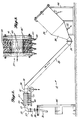
- Figure 2 is a pictorial view of a feed subsystem used in connection with the container filling system of Figure 1;
- Figure 3 is a sectional view of a portion of the feed subsystem of Figure 2 illustrating a dewatering station in the subsystem.
- Figure 4 is a vertical section of the measuring station of Figure 1;
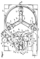
- Figure 5 is a horizontal section of the system of Figure 1 illustrating the path of advance of the filler material through the measuring and discharge stations.
- Figure 6 is a vertical section of a portion of the discharge station of Figure 1 illustrating the position of the discharge station prior to the discharge of filler material into a container;
- Figure 7 is a vertical section of a portion of the discharge station of Figure 1 illustrating the position of the discharge station after the filler material has been discharged into the container;
- Figure 8 is a pictorial view of a container introduction station included in the system of Figure 1; and
- Figure 9 is a horizontal section of the system of Figure 1 illustrating a synchronized drive subsystem used to provide the desired relative orientation and operation of the system components.
- Referring now to Figure 1, a
container filling system 10 constructed in accordance with this invention is shown. As will be appreciated,system 10 can be used to dispense a variety of bulk filler materials into numerous types of containers. In the preferred embodiment, however,system 10 is used to dispense precisely controlled portions of butchered fish, having their heads, fins and entrails removed, into cans. - As shown in FIGURE 1, the container filling system includes a number of subsystems. A material feed subsystem 12 (partially shown) receives a bulk supply of randomly aligned, butchered fish in water.
Feed subsystem 12 then aligns or orients the fish under pressure, packs them, and removes the water to provide a source of aligned fish that is of substantially uniform density. - From the
material feed subsystem 12, the aligned and compressed fish are advanced to ameasuring subsystem 14.Measuring subsystem 14, which operates in a continuous rotational pattern, produces portions of closely controlled weight and volume from the fish supplied byfeed subsystem 12. These measured portions of fish are then advanced to a transfer subsystem 16. - Transfer subsystem 16 transfers the controlled portions of fish produced by measuring
subsystem 14 to adischarge subsystem 18. The continuously rotatingdischarge subsystem 18 dispenses the precisely controlled portions of fish produced by measuringsubsystem 14 into containers advanced through thedischarge subsystem 18 by acontainer advance subsystem 20. To ensure that the various subsystems described above operate in synchronization, a common synchronizeddrive subsystem 22 is provided. - Addressing the various subsystems of
container filling system 10 in greater detail, reference is initially had to thematerial feed subsystem 12 shown in FIGURES 1, 2, 3 and 4. As shown in FIGURE 2,feed subsystem 12 includes atilted hopper 24 designed to receive and temporarily store a supply of butcheredfish 26, in water, that is sufficient to allowsystem 10 to continue operation for short periods, even without the receipt ofadditional fish 26 byhopper 24. As will be appreciated, the inclusion of water allows thefish 26 to be pumped under pressure directly from a butchering station intohopper 24. - Hopper 24 has a
base 28 that is preferably shaped like the frustum of a cone. The resultant taper of thebase 28, which is connected to atubular transfer section 29 by anelbow 30, allows gravity to assist the introduction of butcheredfish 26 into theelbow 30 andtransfer section 29. The transfer offish 26 into, and through,section 29 may be further assisted by the establishment of a pressure in thehopper 24 that is greater than that of the surrounding atmosphere and the maintenance of an adequate flow of water, both of which may be accomplished with the aid of inlet andoutlet ports 31 and 32. Thetapered base 28,elbow 30, andtransfer section 29 are dimensioned to cooperatively orient the butcheredfish 26 substantially longitudinally intransfer section 29. More particularly,fish 26 will be oriented such that their backbones are disposed substantially along the axis ofsection 29 as they travel throughsection 29. - Attached to the upper end of the
transfer section 29 is an elbow 33 that extends into ahorizontal section 34.Section 34 is followed by acompression section 35 that is shaped like the frustum of a cone. As will be appreciated, the variation in the diameter ofsection 35 effects a compression of the fish traveling therethrough. Adewatering station 37 followssection 35 to remove the water that has previously been used to transport butcheredfish 26 in alignment throughsubsystem 12. As shown,station 37 includes a plurality ofsections 39 that each have acylindrical bore 41 extending therethrough. Thevarious sections 39 are coupled end-to-end to define a continued passage for the butcheredfish 26 received fromsection 35. - As shown in FIGURE 3, the
bore 41 of eachsection 39 of thedewatering station 37 is provided with a plurality of circumferentially spaced-apart ports 43 that allow water to escape. Achannel 45 is provided in eachsection 39, extending circumferentially aroundbore 41 and in fluid communication with theports 43. Eachchannel 45 is connected via acoupler 47 to anindividual line 49 of a water outlet system 51. As will be appreciated, the number ofsections 39 andports 43 can be varied to provide the desired dewatering characteristics. Similarly, valves can be included inlines 49 to control the escape of water through theports 43 of eachsection 39 in any manner desired. - While the flow of water aids the longitudinal transport of butchered
fish 26 throughsubsystem 12 prior to reachingstation 37, the diameter of the passage throughstation 37 is sufficiently small to maintain the butcheredfish 26 received therein in substantial alignment. Fromstation 37, the alignedfish 26 traverse a shorthorizontal section 53 of tube, followed by a 90°elbow 55, and a shortvertical section 57 of tube. As this point, the butcheredfish 26 move downward into asecond compression section 59. -
Compression section 59 is shaped like the frustum of a cone and is dimensioned to effect the desired compression of butcheredfish 26. More particularly,section 59, in cooperation with the applied hopper pressure, is designed to compress the dewatered and alignedfish 26 sufficiently to produce a continuous, aligned pack of substantially uniform density for advance to the measuringsubsystem 14. - As with the preceding elements of the
material feed subsystem 12, which are rigid and fixedly attached and sealed in sequence, the outlet of the taperedcompression section 59 is securely connected to aflexible transfer tube 36. The diameter oftransfer tube 36 corresponds to that of the lower end ofsection 59. As shown in FIGURE 2, the connection betweensection 59 andtube 36 is provided by acollar 38 that provides a relatively fluid-tight seal. While theupper end 40 oftube 36 is fixed, as shown in FIGURE 4, thelower end 42 oftube 36, which is connected to therotating measuring subsystem 14 by a standard sanitary couple 61, undergoes horizontal translation in a circular pattern. The resultant offset alignment of the upper and lower ends 40 and 42 oftube 36 introduces two slight elbows in thetube 36, with the offset being limited sufficiently to allow the relatively unimpeded progress of packedfish 26 through thefeed subsystem 12. Although not described in detail, it will be appreciated that the preceding elements of thematerial feed subsystem 12 are supported by a feedsubsystem support structure 46. - Turning now to a description of the measuring
subsystem 14, as shown in FIGURES 1, 4 and 5, it includes a flat, roughlyrectangular guide plate 48 that is supported for horizontal rotation about avertical shaft 50. Acylindrical guide 56 passes throughplate 48 adjacent one end and extends above and belowplate 48. A counterweight 63 is attached to the other end ofplate 48 for balanced operation. Asleeve 44, having an inner diameter corrsponding to that oftube 36, is received withinguide 56 and extends slightly aboveguide 56 to provide the desired connection withtube 36 at couple 61. In this manner, a supply of butcheredfish 26 that is substantially aligned and of substantially uniform density is made available to therotating measuring subsystem 14 under the direction ofguide 56. - As will be appreciated from FIGURES 1 and 5, as
plate 48 andshaft 50 undergo one complete rotation, the lower surface ofguide 56 sweeps out a path that, for part of the rotation, traverses the upper surface of aknife plate 58. Whenguide 56 is positioned overknife plate 58, the spacing between the two parts is sufficiently closely toleranced so that the advance of thefish pack 26 is limited by the upper surface ofknife plate 58. As soon asplate 48 has rotated sufficiently forguide 56 to clear the "trailing"edge 60 ofknife plate 58, however, theknife plate 58 will no longer restrict the advance of packedfish 26 throughguide 56. - At the same time that guide 56 clears
edge 60 ofknife plate 58, a measuringchamber 62 that is vertically aligned withguide 56 in a plane belowplate 58 is advancedpast edge 60 by a horizontalchamber guide wheel 64 rotating in synchronization withguide plate 48. Measuringcontainer 62 is a substantially cylindrical ring having aboss 66 projecting radially about its lower surface. Measuringcontainer 62 is dimensioned to define a volume that corresponds to a predetermined mass offish 26 when packedfish 26 having a particular density are introduced intocontainer 62. Thecontainer guide wheel 64 is rotatably secured toshaft 50 and includes arecess 68 at its perimeter that is dimensioned to receive measuringcontainer 62 and engageboss 66. Because theguide wheel 64 is affixed to the samevertical shaft 50 asguide plate 48, with theguide wheel recess 68 aligned with thefish guide 56 onguide plate 48, the vertical alignment of the measuringcontainer 62 and thefish guide 56 is ensured as the trailingedge 60 ofknife plate 58 is passed. - Although both the top and bottom of measuring
container 62 are open,container 62 rides on abase plate 70 that prevents the escape of packedfish 26 from the bottom ofcontainer 62 when packedfish 26 are introduced under pressure throughguide 56. Similarly, becauseguide 56 and measuringcontainer 62 are relatively closely spaced, the escape of packedfish 26 from the top ofcontainer 62 is substantially prevented. To speed the entry of packedfish 26 into measuringcontainer 62 after the trailingedge 60 ofknife plate 58 is passed, a series of circumferentially alignedports 65 are included inbase plate 70. As will be appreciated, with a vacuum applied toports 65,fish 26 is more readily drawn intocontainer 62. - As the
guide wheel 64 and guideplate 48 continue to rotate the measuringcontainer 62 and guide 56 in synchronization, the knife edge 72 ofknife plate 58 is eventually reached. As shown, knife edge 72 is displaced at an angle with respect to the path of advance ofguide 56 and measuringcontainer 62 to cleanly sever thefish pack 26 betweenguide 56 and measuringcontainer 62 . As a result, aportion 74 of longitudinally alignedfish 26 having a closely controlled weight is produced in measuringcontainer 62. - As will be appreciated from Figures 1 and 5, the control of measuring
container 62 , as it is advanced through the filling and severance operations described above, is accomplished byguide wheel 64 in cooperation with aguide rail 76.Guide rail 76 extends over an arc of approximately 270° and limits the radial movement of measuringcontainer 62 as it is rotated through measuringsubsystem 14 byguide wheel 64. Like therecess 68 inguide wheel 64,guide rail 76 is designed to loosely engage the outer surface of the measuringcontainer 62, includingboss 66. As will be appreciated,guide rail 76 is horizontally secured to thebase plate 70, which, along withvertical shaft 50 andknife plate 58, is supported by a measuringsubsystem support structure 78. - Turning now to a more detailed discussion of the transfer subsystem 16, as shown in Figures 1 and 5, subsystem 16 includes a
forward guide wheel 80 that cooperates with a forward guide surface 82 of arail 83 to transfer measuringcontainer 62 from measuringsubsystem 14 to thedischarge subsystem 18 after the desiredportion 74 offish 26 is produced in thecontainer 62 . A further subsystem 16 also includes areturn guide wheel 84 that cooperates with a return guide surface 86 formed on the opposite side ofrail 83, to return measuringcontainer 62 to measuringsubsystem 14 after theportion 74 has been dispensed into a container by thedischarge subsystem 18. - Considering these elements of the transfer subsystem 16 individually, the
forward guide wheel 80 is a roughly circular plate, corresponding in dimension towheel 64 and mounted for horizontal rotation about avertical drive shaft 88.Guide wheel 80 includes arecess 90 that is designed to cooperatively engage the measuringcontainer 62 and advance it along guide rail surface 82 as theguide wheel 80 is rotated. Guide rail surface 82 defines an arc of approximately 90° andguide rail 83 is secured to thesame base plate 70 as the measuringsubsystem guide rail 76. The interaction between theguide wheel 64 andguide rail 76 of measuringsubsystem 14 and the transfersystem guide wheel 80 andguide rail 83 is synchronized by providing the proper initial orientation ofvertical shafts container 62 is advanced byguide wheel 64 to the end ofguide rail 76, at which point the guide surface 82 ofrail 83 initiates the guidance of measuringcontainer 62 under the influence ofguide wheel 80. - As noted previously, the
forward guide wheel 80 and guide rail surface 82advance measuring container 62 from measuringsubsystem 14 to thedischarge system 18, which dispensesportion 74 into a container and returnscontainer 62 to thereturn guide wheel 84 and guide rail surface 86.Return guide wheel 84 and guide rail surface 86 which form subsystem 16', are of substantially the same construction as, and provide a mirrored operation of,forward guide wheel 80 and guide rail surface 82. More particularly,wheel 84 and surface 86 cooperatively receive measuringcontainer 62 as it exits thedischarge subsystem 18 and transfer it in an arcuate path until control ofcontainer 62 is resumed by the measuringsubsystem guide wheel 64 andguide rail 76. - Like the
forward guide wheel 80, returnguide wheel 84 is an approximately circular plate that includes arecess 92 constructed to receive the measuringcontainer 62 .Wheel 84 is secured for horizontal rotation about avertical shaft 94. The guide surface 86 ofrail 83 defines an arc of approximately 90°. - Turning now to a discussion of the
discharge subsystem 18, as shown in Figures 1, 6 and 7,discharge subsystem 18 includes adischarge assembly 104 that receivesempty product containers 114 and filled measuring containers in vertical alignment and discharges theportions 74 of fish into the product containers. Thedischarge assembly 104 is secured to avertical shaft 102 by ahub 106 and, as a result, is horizontally rotatable. In the preferred arrangement, threearms 108, located approximately 120° apart, project radially fromhub 106. At the end of eacharm 108 is adischarge station 110, where the actual transfer ofportion 74 from measuringcontainer 62 toproduct container 114 occurs. - Each
discharge station 110 includes a horizontally disposedplatform 112 for receiving and supporting acontainer 114. Thecontainer 114 is further supported by a horizontalcontainer receiving plate 116 that is spaced slightly aboveplatform 112 and that includes a semicircular recess for receiving and engaging a portion of the side ofcontainer 114.Plate 116 and aguide rail 120 that is disposed aboutdischarge assembly 104 cooperatively retain thecontainer 114 onplatform 112 as thedischarge assembly 104 is rotated aboutshaft 102. - The vertical position of
platform 112 andplate 116 is such that acontainer 114 is supported for rotation through thedischarge subsystem 18 at a level below thebase plate 70. Vertically aligned withbase plate 70 on eachdischarge station 110 is a measuringcontainer receiving plate 122. As will be appreciated, each receivingplate 122 is located above the correspondingcontainer receiving plate 116 and is recessed and slotted to receive the measuringcontainer 62 and support it viaboss 66. The receivingplate 122 also cooperates with theguide rail 120, which extends vertically to the level ofplate 122, to retain the measuringcontainer 62 in vertical alignment withproduct container 114 as thedischarge assembly 104 rotates aboutvertical shaft 102. - To effect the discharge of
portion 74 fromcontainer 62 intocontainer 114, aplunger tip 124 is secured to the lower end of a vertically alignedplunger arm 126 disposed abovechamber 62. Theplunger arm 126 is slidably received between upper andlower support brackets support arm 132 and fixed with respect tostation 110. The vertical displacement ofplunger arm 126 is controlled by upper and lowerbearing plate assemblies lower support brackets plate assemblies bearings cam 142 that controls the vertical displacements ofassemblies plunger arm 126. -
Cam 142 is a continuous loop of material having a rectangular cross section and is supported around thedischarge assembly 104 by asupport structure 144. The vertical height ofcam 142 with respect to, for example, thearms 108 of thedischarge assembly 104 varies approximately sinusoidally over 360°. Given the cooperation of bearingplate assemblies cam 142, it will be appreciated that asdischarge assembly 104 rotates, the variation in the height ofcam 142 over thearm 108 effects a corresponding displacement in theplunger tip 124. - As will be described in greater detail below, the orientation of
cam 142 with respect to thedischarge assembly 104 is such that the receipt of a filled measuringcontainer 62 by astation 110 corresponds to a downward slope incam 142, causing theplunger tip 124 to move downward and force theportion 74 of fish fromcontainer 62 into thecontainer 114 below. The diameter and alignment ofplunger tip 124, measuringcontainer 62 andproduct container 114 are such that air is easily vented fromcontainer 114 as the portion of fish is inserted. More particularly, theplunger tip 124 is slightly smaller in diameter thancontainer 114 and its axis is offset from the centre of thecontainer 114 supported onplatform 112. As will be appreciated, thedischarge station 110 continues to rotate back toward the transfer subsystem 16 ascontainer 114 is filled and eventually thecam 142 will exhibit an upward slope causing theplunger tip 124 to be withdrawn fromcontainer 62 . - Turning now to a discussion of the product
container advance subsystem 20, reference is had to Figures 1, 5 and 8.Subsystem 20 is responsible for the introduction and removal ofproduct containers 114 from the horizontally disposedplatforms 112 of therotating discharge stations 110. The introduction of acontainer 114 onto eachplatform 112 is accomplished through the use of arubber acceleration wheel 146 that acceleratescontainers 114 from their resting place in arack 150 and into thecammed recess 148 of arotating timing wheel 149. More particularly, the horizontal rotation of thetined acceleration wheel 146 aboutvertical shaft 152 causes the wheel's tines to engage theforward-most container 114 inrack 150 and accelerate and direct it into thecammed recess 148.Cammed recess 148 is designed to, first, receive the acceleratedcontainer 114 and, then guide it in a controlled and timed fashion ontoplatform 112. As will be appreciated, this control is achieved by the horizontal rotation oftiming wheel 149 aboutvertical shaft 88 in synchronization with the rotation ofchamber guide wheel 80 anddischarge assembly 104. In this manner, a smooth transfer of thecontainer 114 into thedischarge subsystem 18 is affected. - To remove the
containers 114 fromplatforms 112, a projectingarm 154 is positioned in the horizontal path of thecontainers 114 just prior to the rotation ofdischarge assembly 104 back to thereturn wheel 84 of transfer subsystem 16. The projectingarm 154, in cooperation with aguide rail 156, directscontainers 114 fromplatform 112 to aconveyor system 157 for further processing or packaging, including, for example, the hermetic sealing ofcontainers 114. - As noted previously, the required synchronous operation of the various subsystems is maintained by the
synchronized drive subsystem 22, located in part belowbase plate 70. More particularly, as shown in Figure 9, thesynchronized drive subsystem 22 includes a plurality ofpulleys vertical shafts second belt 170 traverses asecond pulley 172 onshaft 50 and adrive pulley 174 secured to amain drive shaft 176. As a result, the rotation ofdrive shaft 176 effects the desired synchronous rotation ofshafts various pulleys 158, the desired relative rotational rates and angular alignments of the subsystem components can be achieved. In particular,shafts shaft 102. As will be appreciated,drive subsystem 22 may alternatively employ gears or chain-and-sprocket combinations to synchronously drive the various shafts. - Reviewing now the overall operation of the
container filling system 10, reference is again had to Figure 1. Operation will be assumed to commence with ahopper 24 full of butchered fish and aligned, dewatered andcompressed fish 26 being available at the end of theflexible transfer tube 36. Measuringcontainers 62 are provided in therecesses guide wheels container receiving plate 122 of eachdischarge station 110. Similarly, a supply ofproduct containers 114 is available andcontainers 114 are appropriately positioned on eachplatform 112 of thedischarge stations 110. - Following one measuring
container 62 through theentire filling system 10, let us begin with theguide plate 48 and guide 56 of measuringsubsystem 14 rotated to the position designated A in Figure 5. As shown in the broken line view of Figure 4, at this point, measuringcontainer 62 is located belowknife plate 58 and is being advanced toward the trailingedge 60 of theknife plate 58. As thechamber guide wheel 64 rotates measuringcontainer 62 past trailingedge 60, theguide 56 coupled toflexible transfer tube 36 aboveknife plate 58 simultaneously passes trailingedge 60, forcing the pressurized, longitudinally alignedfish 26 of substantially uniform density into the measuringchamber 62 againstbase plate 70, as shown in Figure 4. - As measuring
container 62 is further rotated byguide wheel 64, it eventually reaches the knife edge 72 ofknife plate 58, designated B in Figure 5. The knife edge 72 passes between the vertically spaced measuringcontainer 62 and guide 56, severing aportion 74 of fish having a predetermined volume. Given the relatively uniform density of the fish traversingflexible tube 36,portion 74 will also exhibit a relatively closely toleranced weight. In addition, given the longitudinal alignment and compensation of thefish pack 26 withintube 36 andchamber 62, theportion 74 will have a relatively uniform appearance when viewed from above, the skin offish 26 being seen primarily in cross section, and will not interfere with sealing of thecontainer 114. - Further rotation of
guide wheel 64advances measuring container 62 to the end of theguide rail 76. At this point, designated C in Figure 5, the forwardtransfer guide wheel 80 and guide rail surface 82 of transfer subsystem 16 engage measuringcontainer 62 and transport it in an arcuate path covering approximately 90° untilcontainer 62 is engaged by the measuringcontainer receiving plate 122 of adischarge station 110 on the synchronously rotatingdischarge assembly 104. - Given the introduction of a
product container 114 ontoplatform 112 by theacceleration wheel 146, thecontainer 114 is positioned immediately below theportion 74 in measuringcontainer 62 and theplunger arm 126 andplunger tip 124 are disposed immediately aboveportion 74 bysupport brackets container 62 is received bystation 110. This point is designated D in Figure 5 and a partial section of thedischarge station 110 at this point is shown in Figure 6. Asdischarge assembly 104 rotates between points D and E in Figure 5, theplunger arm 126 traverses a downwardly sloping section ofcam 142 which causes it to move downward. As theplunger arm 126 drops,plunger tip 124 forces theportion 74 of fish fromcontainer 62 intocontainer 114 in the manner shown in Figure 7.Cam 142 andplunger tip 124 are at their lowest vertical position at point E. From there, continued rotation ofdischarge station 110 back toward the transfer subsystem 16 at point F causesstation 110 to traverse an upwardly sloping section ofcam 142. Ultimately,plunger tip 124 rises and achieves its highest elevation 180° from point E. - Before the
discharge station 110 reaches the return section of transfer subsystem 16, the projectingarm 154 removes the filledcontainer 114 from the horizontally disposedplatform 112, at the point designated G in Figure 5. Finally, at point F, returnchamber guide wheel 84 and guide rail surface 86 engage the measuringcontainer 62 , transferring it fromdischarge subsystem 18 back to theguide wheel 64 of measuringsubsystem 14. From here, the process repeats itself. - As will be appreciated, the variation in operational speeds of measuring
subsystem 14 anddischarge subsystem 18 is attributable to different requirements of the two substations. More particularly, while the measuring process can be performed relatively rapidly, discharge of theportion 74 of fish intocontainer 114 is slowed by the fact that air must be allowed to escape from thecontainer 114. While this is accomplished in the preferred embodiment by the use of the offset andsmall plunger tip 124 described above, some delay is still incurred. More particularly, it is believed that the measuringsubsystem 14 can operate effectively three times as fast as thedischarge subsystem 18. For that reason, a measuringsubsystem 14 that produces asingle portion 74 per revolution is used in connection with adischarge subsystem 18 that fills three containers per revolution. - Other embodiments of the invention may, for example, be readily employed to discharge various filler materials into different container types. For example, certain nonhomogenous media that are incapable of achieving a uniform density when compressed may be dispensed by the disclosed system to provide closely controlled volumes of material to a container. Further, the exact construction of, for example, the guide wheels and rails can be varied as desired. Similarly, the discharge assembly could be constructed as a continuous wheel and could employ a variety of cam contours.
Claims (7)
- A container-filling system (10) for introducing controlled volumes of filler material into containers, the system comprising:
measuring means (14,62) rotatable about a primary axis and arranged to receive predetermined volumes (74) of filler material;
feeder means (12) arranged to introduce filler material into said measuring means under pressure and along a first axis which is offset from said primary axis and defined with respect to said measuring means, and
rotatable discharge means (18,110) which is arranged to discharge predetermined volumes of filler material from said measuring means into product-receiving containers (114), characterised in that a transfer means (16) is arranged to transfer removable measuring containers (62) containing predetermined volumes of filler material from said measuring means (14,62) to said discharge means (18,110) into alignment with said discharge means and with said product-receiving containers (114), said discharge means being arranged to rotate, together with the measuring containers, about a secondary axis which is different from said primary axis and to discharge said predetermined volumes (74) of filler material along a third axis defined by the aligned measuring containers (62), discharge means and product-receiving containers (114), said third axis being offset from said secondary axis and rotating with said discharge means and said measuring containers. - A container-filling system (10) as claimed in claim 1 wherein said discharge means (18,110) is arranged continuously to discharge said filler material whilst rotating about said secondary axis.
- A container-filling system (10) as claimed in claim 1 or claim 2 further characterised in that said discharge means (18,110) is arranged to discharge a plurality of predetermined volumes (74) of filler material along a respective plurality of third axes which are offset from said secondary axis and defined with respect to said discharge means.
- A container-filling system (10) as claimed in any preceding claim, further characterised in that said transfer means (16) is arranged to rotate about a fourth axis which is offset from said primary and secondary axes.
- A container-filling system (10) as claimed in any preceding claim further characterised in that a further transfer means (16¹) is arranged to return empty measuring containers (62) from said discharge means (18,110) to said measuring means (14,62).
- A container-filling system (10) as claimed in claim 5, further characterised in that said further transfer means (16¹) is arranged to rotate about a fifth axis which is offset from said primary and secondary axes.
- A container-filling system (10) as claimed in any preceding claim wherein said feed means (12) comprises a tube (36) coupled to a tubular guide (56) which is aligned with said first axis and mounted for rotation with said measuring means (14,62) so as to discharge filler material into a measuring container (62) which is aligned therewith, a fixed knife plate (58) being arranged to cut the filler material in a gap between the downstream end of the tubular guide (56) and a mouth of the measuring (62) as the tubular guide (56) traverses a surface of the knife plate during rotation of said measuring means (14,62).
Applications Claiming Priority (2)
| Application Number | Priority Date | Filing Date | Title |
|---|---|---|---|
| US8197287A | 1987-08-05 | 1987-08-05 | |
| US81972 | 1987-08-05 |
Related Child Applications (1)
| Application Number | Title | Priority Date | Filing Date |
|---|---|---|---|
| EP93101240.5 Division-Into | 1993-01-28 |
Publications (3)
| Publication Number | Publication Date |
|---|---|
| EP0302652A2 EP0302652A2 (en) | 1989-02-08 |
| EP0302652A3 EP0302652A3 (en) | 1990-04-11 |
| EP0302652B1 true EP0302652B1 (en) | 1993-11-18 |
Family
ID=22167576
Family Applications (2)
| Application Number | Title | Priority Date | Filing Date |
|---|---|---|---|
| EP88306877A Expired - Lifetime EP0302652B1 (en) | 1987-08-05 | 1988-07-26 | Container filling system |
| EP93101240A Withdrawn EP0549563A1 (en) | 1987-08-05 | 1988-07-26 | Feed system for aligning butchered fish |
Family Applications After (1)
| Application Number | Title | Priority Date | Filing Date |
|---|---|---|---|
| EP93101240A Withdrawn EP0549563A1 (en) | 1987-08-05 | 1988-07-26 | Feed system for aligning butchered fish |
Country Status (5)
| Country | Link |
|---|---|
| EP (2) | EP0302652B1 (en) |
| JP (1) | JPH01111626A (en) |
| KR (1) | KR890003618A (en) |
| CA (1) | CA1300576C (en) |
| DE (1) | DE3885672T2 (en) |
Families Citing this family (2)
| Publication number | Priority date | Publication date | Assignee | Title |
|---|---|---|---|---|
| ES2150346B1 (en) * | 1998-01-12 | 2001-06-01 | Hermanos Rodriguez Gomez S A | CUTTING AND CANNED MECHANISM FOR PRESERVATION PACKAGERS. |
| DE102010002172A1 (en) * | 2010-02-22 | 2011-08-25 | Robert Bosch GmbH, 70469 | Device for controlling the directional stability of a belt |
Family Cites Families (6)
| Publication number | Priority date | Publication date | Assignee | Title |
|---|---|---|---|---|
| US2127393A (en) * | 1937-10-11 | 1938-08-16 | Charles L Doney | Packing machine |
| US2321885A (en) * | 1938-04-01 | 1943-06-15 | Allen Sherman Hoff Co | Material handling system |
| US3513626A (en) * | 1967-02-28 | 1970-05-26 | Zoya Valentinovna Zhavoronkova | Device for putting food-stuffs into cans |
| JPS5754551A (en) * | 1980-09-16 | 1982-04-01 | Kyoei Zoki Kk | Apparatus for arranging and supplying fish body |
| JPS6240243A (en) * | 1985-08-08 | 1987-02-21 | アルフア −ラヴアル フ−ド アンド デイリイ エンジニアリング ア−ベ− | Production of fish meat material |
| JPS62146128A (en) * | 1985-12-16 | 1987-06-30 | ハウス食品工業株式会社 | Sterilization filling equipment |
-
1988
- 1988-07-26 DE DE88306877T patent/DE3885672T2/en not_active Expired - Fee Related
- 1988-07-26 EP EP88306877A patent/EP0302652B1/en not_active Expired - Lifetime
- 1988-07-26 EP EP93101240A patent/EP0549563A1/en not_active Withdrawn
- 1988-08-03 CA CA000573696A patent/CA1300576C/en not_active Expired - Lifetime
- 1988-08-05 JP JP63194670A patent/JPH01111626A/en active Pending
- 1988-08-05 KR KR1019880010013A patent/KR890003618A/en not_active Ceased
Also Published As
| Publication number | Publication date |
|---|---|
| DE3885672T2 (en) | 1994-03-10 |
| EP0302652A2 (en) | 1989-02-08 |
| CA1300576C (en) | 1992-05-12 |
| JPH01111626A (en) | 1989-04-28 |
| EP0302652A3 (en) | 1990-04-11 |
| KR890003618A (en) | 1989-04-15 |
| DE3885672D1 (en) | 1993-12-23 |
| EP0549563A1 (en) | 1993-06-30 |
Similar Documents
| Publication | Publication Date | Title |
|---|---|---|
| US3828660A (en) | Machine for making ice cream cookie sandwiches and similar food products | |
| US6357495B1 (en) | Device for filling a blister band with products | |
| US4019547A (en) | Can filling method and apparatus | |
| US4306335A (en) | Method and apparatus for cutting poultry | |
| WO1997011883A1 (en) | A packaging machine and a method for packaging units in portions | |
| US2092773A (en) | Packing machine | |
| US4961446A (en) | Container filling system | |
| US10583947B2 (en) | Method and apparatus for filling capsules with loose material and for their sealing | |
| US4893660A (en) | Container filling system | |
| US12552574B2 (en) | System adapted to promote re-utilization of a rejected container loaded with content | |
| US6622458B2 (en) | High speed fish canning method and apparatus | |
| US5549143A (en) | Apparatus with vacuum recovery for adding flavor materials to beverages | |
| CN109466814B (en) | Apparatus for conveying lids to a can seamer | |
| EP0302652A2 (en) | Container filling system | |
| EP1310430B1 (en) | A method and a device for feeding confectionery products to a wrapping machine | |
| US6625961B1 (en) | Multiple station bagging system | |
| US3136103A (en) | Machine for loading pineapple slices | |
| US5810150A (en) | Collator for a food product packaging machine, and method of use thereof | |
| US5408791A (en) | Apparatus for portion packing of lumpy goods | |
| EP0575047A2 (en) | Apparatus for introducing filler material into containers | |
| US2195882A (en) | Can packing machine | |
| EP1270458A1 (en) | Supplier | |
| US2628758A (en) | Packaging machine | |
| US3456418A (en) | Packing apparatus | |
| AU742490B2 (en) | Packaging method and apparatus |
Legal Events
| Date | Code | Title | Description |
|---|---|---|---|
| PUAI | Public reference made under article 153(3) epc to a published international application that has entered the european phase |
Free format text: ORIGINAL CODE: 0009012 |
|
| AK | Designated contracting states |
Kind code of ref document: A2 Designated state(s): BE DE GB LU NL |
|
| PUAL | Search report despatched |
Free format text: ORIGINAL CODE: 0009013 |
|
| AK | Designated contracting states |
Kind code of ref document: A3 Designated state(s): BE DE GB LU NL |
|
| 17P | Request for examination filed |
Effective date: 19901008 |
|
| 17Q | First examination report despatched |
Effective date: 19910320 |
|
| GRAA | (expected) grant |
Free format text: ORIGINAL CODE: 0009210 |
|
| AK | Designated contracting states |
Kind code of ref document: B1 Designated state(s): BE DE GB LU NL |
|
| XX | Miscellaneous (additional remarks) |
Free format text: TEILANMELDUNG 93101240.5 EINGEREICHT AM 26/07/88. |
|
| REF | Corresponds to: |
Ref document number: 3885672 Country of ref document: DE Date of ref document: 19931223 |
|
| PLBE | No opposition filed within time limit |
Free format text: ORIGINAL CODE: 0009261 |
|
| STAA | Information on the status of an ep patent application or granted ep patent |
Free format text: STATUS: NO OPPOSITION FILED WITHIN TIME LIMIT |
|
| EPTA | Lu: last paid annual fee | ||
| 26N | No opposition filed | ||
| PGFP | Annual fee paid to national office [announced via postgrant information from national office to epo] |
Ref country code: GB Payment date: 19950609 Year of fee payment: 8 |
|
| PGFP | Annual fee paid to national office [announced via postgrant information from national office to epo] |
Ref country code: DE Payment date: 19950622 Year of fee payment: 8 |
|
| PGFP | Annual fee paid to national office [announced via postgrant information from national office to epo] |
Ref country code: LU Payment date: 19950701 Year of fee payment: 8 |
|
| PGFP | Annual fee paid to national office [announced via postgrant information from national office to epo] |
Ref country code: NL Payment date: 19950731 Year of fee payment: 8 |
|
| PGFP | Annual fee paid to national office [announced via postgrant information from national office to epo] |
Ref country code: BE Payment date: 19950821 Year of fee payment: 8 |
|
| PG25 | Lapsed in a contracting state [announced via postgrant information from national office to epo] |
Ref country code: LU Free format text: LAPSE BECAUSE OF NON-PAYMENT OF DUE FEES Effective date: 19960726 Ref country code: GB Effective date: 19960726 |
|
| PG25 | Lapsed in a contracting state [announced via postgrant information from national office to epo] |
Ref country code: BE Effective date: 19960731 |
|
| BERE | Be: lapsed |
Owner name: PROMATION INC. Effective date: 19960731 |
|
| PG25 | Lapsed in a contracting state [announced via postgrant information from national office to epo] |
Ref country code: NL Effective date: 19970201 |
|
| GBPC | Gb: european patent ceased through non-payment of renewal fee |
Effective date: 19960726 |
|
| NLV4 | Nl: lapsed or anulled due to non-payment of the annual fee |
Effective date: 19970201 |
|
| PG25 | Lapsed in a contracting state [announced via postgrant information from national office to epo] |
Ref country code: DE Effective date: 19970402 |