EP0301712A1 - Data encoding - Google Patents
Data encoding Download PDFInfo
- Publication number
- EP0301712A1 EP0301712A1 EP88306060A EP88306060A EP0301712A1 EP 0301712 A1 EP0301712 A1 EP 0301712A1 EP 88306060 A EP88306060 A EP 88306060A EP 88306060 A EP88306060 A EP 88306060A EP 0301712 A1 EP0301712 A1 EP 0301712A1
- Authority
- EP
- European Patent Office
- Prior art keywords
- values
- output
- order
- address
- latch
- Prior art date
- Legal status (The legal status is an assumption and is not a legal conclusion. Google has not performed a legal analysis and makes no representation as to the accuracy of the status listed.)
- Granted
Links
Images
Classifications
-
- H—ELECTRICITY
- H04—ELECTRIC COMMUNICATION TECHNIQUE
- H04N—PICTORIAL COMMUNICATION, e.g. TELEVISION
- H04N19/00—Methods or arrangements for coding, decoding, compressing or decompressing digital video signals
- H04N19/10—Methods or arrangements for coding, decoding, compressing or decompressing digital video signals using adaptive coding
- H04N19/169—Methods or arrangements for coding, decoding, compressing or decompressing digital video signals using adaptive coding characterised by the coding unit, i.e. the structural portion or semantic portion of the video signal being the object or the subject of the adaptive coding
- H04N19/18—Methods or arrangements for coding, decoding, compressing or decompressing digital video signals using adaptive coding characterised by the coding unit, i.e. the structural portion or semantic portion of the video signal being the object or the subject of the adaptive coding the unit being a set of transform coefficients
-
- H—ELECTRICITY
- H04—ELECTRIC COMMUNICATION TECHNIQUE
- H04N—PICTORIAL COMMUNICATION, e.g. TELEVISION
- H04N19/00—Methods or arrangements for coding, decoding, compressing or decompressing digital video signals
- H04N19/10—Methods or arrangements for coding, decoding, compressing or decompressing digital video signals using adaptive coding
- H04N19/102—Methods or arrangements for coding, decoding, compressing or decompressing digital video signals using adaptive coding characterised by the element, parameter or selection affected or controlled by the adaptive coding
- H04N19/129—Scanning of coding units, e.g. zig-zag scan of transform coefficients or flexible macroblock ordering [FMO]
-
- H—ELECTRICITY
- H04—ELECTRIC COMMUNICATION TECHNIQUE
- H04N—PICTORIAL COMMUNICATION, e.g. TELEVISION
- H04N19/00—Methods or arrangements for coding, decoding, compressing or decompressing digital video signals
- H04N19/10—Methods or arrangements for coding, decoding, compressing or decompressing digital video signals using adaptive coding
- H04N19/134—Methods or arrangements for coding, decoding, compressing or decompressing digital video signals using adaptive coding characterised by the element, parameter or criterion affecting or controlling the adaptive coding
- H04N19/146—Data rate or code amount at the encoder output
- H04N19/149—Data rate or code amount at the encoder output by estimating the code amount by means of a model, e.g. mathematical model or statistical model
-
- H—ELECTRICITY
- H04—ELECTRIC COMMUNICATION TECHNIQUE
- H04N—PICTORIAL COMMUNICATION, e.g. TELEVISION
- H04N19/00—Methods or arrangements for coding, decoding, compressing or decompressing digital video signals
- H04N19/60—Methods or arrangements for coding, decoding, compressing or decompressing digital video signals using transform coding
-
- H—ELECTRICITY
- H04—ELECTRIC COMMUNICATION TECHNIQUE
- H04N—PICTORIAL COMMUNICATION, e.g. TELEVISION
- H04N19/00—Methods or arrangements for coding, decoding, compressing or decompressing digital video signals
- H04N19/10—Methods or arrangements for coding, decoding, compressing or decompressing digital video signals using adaptive coding
- H04N19/134—Methods or arrangements for coding, decoding, compressing or decompressing digital video signals using adaptive coding characterised by the element, parameter or criterion affecting or controlling the adaptive coding
- H04N19/146—Data rate or code amount at the encoder output
Definitions
- the present invention relates to an apparatus and method for encoding a set of values - eg of transform coefficients in a video coder.
- the invention provides a method for encoding a set of values, comprising: receiving the values in a first order; examining the values in the said first order, to identify, of those values which meet a predetermined criterion, which value occupies the highest position in each of a plurality of predetermined orders of the values and to produce a signal indicating that position; comparing the said signals to identify that one of the predetermined orders having the lowest indicated position; and producing, as output, the values in the order thus identified.
- the video coder shown in Figure 1 has a video input 1, and an analogue to digital converter 2. This is followed by a transform coder 3.
- Each frame of the picture is notionally divided into blocks of picture elements (pixels) and each block subjected to a two-dimensional transform such as the discrete cosine transform (DCT) to produce a block of coefficients.
- DCT discrete cosine transform
- One object of conversion into the transform domain is to effect a reduction in the quantity of data which needs to be encoded for transmission, since the number of bits used for encoding each coefficient can be tailored to the relative contribution of that coefficient to the picture quality. In particular, coefficients which are insignificantly small or zero need not be transmitted.
- the transform coder output is supplied to a sequence selection unit 4, and a resequencer 5 which outputs the coefficients of a block in an order - determined by the unit 4 - different from that in which they were received.
- the selector 4 is shown in more detail in Figure 3 and has an input to which a set of 64 coefficients for each block in turn are supplied by the transform coder 3.
- the processing of a single block will be described, it being understood that processing of subsequent blocks occurs in like manner.
- An address generator 11 produces a sequence of 64 unique addresses synchronously with the appearance of the coefficients at the input. The sequence in which they appear is immaterial: for the purposes of further description it will be assumed that the generator is a 6-bit binary counter and addresses are the numbers shown in Figure 2.
- Assessment means 12 serves to ascertain which of the eight possible orders is best suited to the transmission of the particular block. Each address in turn is passed to it, along with the corresponding coefficient, the latter via a circuit 10 which produces a '1' output if the coefficient is non-zero.
- the assessment means 12 has eight sections 12(1)-12(8), one of which is shown in Figure 4.
- a comparator 124 which receives the outputs of the memory 122 and the latch 123 and produces a '1' output if the former is greater than the latter.
- the output of the comparator and the output of the circuit 10 of figure 3 drive a load enable input of the latch 123 via an AND gate 127.
- Each of the sections 12(1)-12(8) is identical except for the content of the look up table 122 which corresponds in each case to a respective one of the eight orders - although if the order in which the coefficients were originally supplied is one of the eight, then one section could omit the table 122.
- the outputs of the eight sections are compared to determine which is the lowest.
- This function is performed by a comparator tree ( Figure 3) consisting of six read-only memories 13-19 each of which receives two addresses from assessment section outputs or an earlier such memory and produces as output the lower address.
- the outputs min1 ... min6 access a further read-only memory 20 to produce a code indicating which of the eight sections provided the lowest address, the address itself appearing at the output of the last stage 19 of the tree.
- the resequencer 5 is shown in figure 5. (The address generator 11 is shown again for clarity).
- the coefficient selection operates in two phases, the first of which has been described above. During this first phase, the coefficients are stored in a store 21 with the aid of the address generator 11. In the second phase, the coefficients are read out from the store; for this purpose the address generator 11 again cycles through its sequence, as before, but the addresses generated pass to the store 21 via a read-only memory 22 containing eight translation tables each of which is the reverse of the contents of all eight stores 12(1)-12(8) - ie the generated address is interpreted as the position in the required order and the table provides the corresponding store address.
- Which of the eight tables is used is determined by the output of the read-only memory 20 which is applied to the higher order address lines of the memory 22. In this way the coefficients are read out in the selected order.
- the output of the comparator 19 is fed to a comparator 23 which produces a "last coefficient" pulse when the address generator reaches the address indicated. This pulse can be used to prevent the zero coefficients being entered into the output buffer 6 ( Figure 1) and hence to the output 7 of the coder.
- the two phases can be carried out simultaneously, the store 21 actually consisting of two stores one of which is being written to whilst the other is being read out.
- Figure 6 shows a modified version of the section shown in Figure 4, in which the function of the lookup table 122 and comparator 124 are performed by a read-only memory 128.
- This may be regarded as having a row address R provided by the address generator 11 and column address C provided by the output of the latch 123. All locations having a translated row address greater than the column address contain the translated row address; other locations contain the column address.
- the buffer 6 may be preceded by other coding arrangements such as a variable length coder.
- figure 1 shows the output of the sequence selector 4 connected to the output buffer 6, so that the sequence code output by the lookup table 20 of figure 3 is included in the transmitted data.
- the number of coefficients sent may be communicated explicitly (by transmitting also the output of the comparator 19) or implicitly - as is assumed below - by transmitting an end of run code following the last coefficient.
- the circuit shown in figure 5 may also be used in a decoder.
- the received signal would first be preprocessed (not shown) by a variable length decoder or other means appropriate to the method of transmission used.
- the sequence code is stripped by an additional unit 24 (shown in broken lines) and supplied to the lookup table 22.
- the coefficients are entered into the store 21 by means of the address generator 11 (driven by suitable clock recovery means, not shown) and read out using the part of the lookup table 22 selected by the received sequence code. They may then be subjected to an inverse transform operation.
- a typical program listing in pseudo-language is set out below for the sequence selection.
- the first part of the "ACTION' segment performs the same function as the assessment means in figure 3 and finds the position of the last non-zero coefficient in each scanning order.
- the second part examines these positions in turn to find the minimum and performs the same function as the tree structured comparators 13-20 in figure 3.
- the program assumes 64-element blocks, but any desired block size may of course be used.
- DECLARE VALUE (64) Transform coefficient values TABLE (n, 64) Array of order tables for n sequences HIGHEST (n) Array to store highest position so far for each sequence SEQ Sequence counter COEFF Coefficient counter TEMP Workspace register BEST Workspace register END DECLARE (Selected Sequence now indicated by BEST and number of coefficients to be sent is in TEMP).
Abstract
Description
- The present invention relates to an apparatus and method for encoding a set of values - eg of transform coefficients in a video coder.
- According to one aspect of the invention there is provided an apparatus for encoding a set of values, comprising:
assessment means for receiving the values in a first order and having a plurality of sections each arranged in accordance with a respective different predetermined order of the values to examine the values in the said first order, to identify, of those values which meet a predetermined criterion, which value occupies the highest position in the said respective predetermined order, and to produce an output indicating that position;
comparator means responsive to the output of the assessment means to identify that producing the lowest indicated position; and
means for output of the values in the order corresponding to the identified assessment means. - In another aspect, the invention provides a method for encoding a set of values, comprising:
receiving the values in a first order;
examining the values in the said first order, to identify, of those values which meet a predetermined criterion, which value occupies the highest position in each of a plurality of predetermined orders of the values and to produce a signal indicating that position;
comparing the said signals to identify that one of the predetermined orders having the lowest indicated position; and
producing, as output, the values in the order thus identified. - Other optional features of the invention are defined in the sub-claims.
- One embodiment of the invention will now be described, by way of example, with reference to the accompanying drawings, in which:
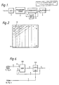
- Figure 1 is a block diagram of a coder;
- Figure 2 illustrates a block of transform coefficients;
- Figure 3 is a block diagram of the
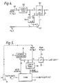
sequence selector 4 of figure 1; - Figure 4 is a block diagram of the assessment means 12 of figure 3;
- Figure 5 is a block diagram of the
resequencer 5 of figure 1; and - Figure 6 is a block diagram of an alternative form of the assessment means 12 of figure 3.
- The video coder shown in Figure 1 has a
video input 1, and an analogue todigital converter 2. This is followed by atransform coder 3. Each frame of the picture is notionally divided into blocks of picture elements (pixels) and each block subjected to a two-dimensional transform such as the discrete cosine transform (DCT) to produce a block of coefficients. One object of conversion into the transform domain is to effect a reduction in the quantity of data which needs to be encoded for transmission, since the number of bits used for encoding each coefficient can be tailored to the relative contribution of that coefficient to the picture quality. In particular, coefficients which are insignificantly small or zero need not be transmitted. - Other redundancy reduction techniques such as the use of inter-frame comparison (before or after the transform coder) so that data needs to be transmitted only in respect of blocks which have changed between frames, differential coding, and the use of motion compensation, may also be employed if desired. However these, like transform coding itself, are well known in the picture coding field and will not be described further.
- The transform coder output is supplied to a
sequence selection unit 4, and aresequencer 5 which outputs the coefficients of a block in an order - determined by the unit 4 - different from that in which they were received. - As previously mentioned, each frame (or field) of the picture is divided into blocks; for example 8 pixel x 8 line blocks may be employed. After transformation, each block gives rise to an 8x8 block of coefficients, as illustrated schematically in Figure 2 with the coefficients numbered (arbitrarily) 0 to 63. Conventionally (though not necessarily) these are represented as a matrix ordered as to sequency, the upper left coefficient (0) representing the mean level of brightness of the block (the "dc" coefficient) and coefficients increasing in horizontal and vertical sequency as one moves to the right or downwards. "Sequency" is the equivalent in the case of a discrete transform of frequency in the case of a continuous transform; the higher sequency coefficients carry information about the higher spatial frequency components of the picture. Generally these are smaller than the dc or lower sequency coefficients and commonly are more coarsely quantised before transmission. Some of these indeed may be zero and others may be so small as to be set to zero by a thresholding process.
- In order to reduce the number of coefficients that require to be transmitted, it is proposed to vary the sequence in which the coefficients are transmitted, by defining a number - perhaps eight - of different orders of transmission. Two possible sequences are illustrated by arrowed lines A,B in Figure 2. Once the last non-zero coefficient has been sent, transmission (for that block) can be terminated. The purpose of the
selector 4 is to determine which order of transmission results in the maximum number of zeros at the end of the sequence, thereby minimising the number of coefficients that have to be sent. - The
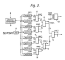
selector 4 is shown in more detail in Figure 3 and has an input to which a set of 64 coefficients for each block in turn are supplied by thetransform coder 3. The processing of a single block will be described, it being understood that processing of subsequent blocks occurs in like manner. - An
address generator 11 produces a sequence of 64 unique addresses synchronously with the appearance of the coefficients at the input. The sequence in which they appear is immaterial: for the purposes of further description it will be assumed that the generator is a 6-bit binary counter and addresses are the numbers shown in Figure 2. Assessment means 12 serves to ascertain which of the eight possible orders is best suited to the transmission of the particular block. Each address in turn is passed to it, along with the corresponding coefficient, the latter via acircuit 10 which produces a '1' output if the coefficient is non-zero. The assessment means 12 has eight sections 12(1)-12(8), one of which is shown in Figure 4. - The addresses, applied at
input 121, pass to a look up table stored in a read-only memory 122. This stores the position, in the relevant one of the eight orders, of each coefficient - ie the output of thememory 122 is a translated address. For example, assuming order B of Figure 2,address 10 represents the eighth coefficient and that order and therefore address 10 translates to 7. - As each translated address appears at the output of the
memory 122 it is loaded into alatch 123 if - (a) it is greater than the previous address stored in the latch
AND - (b) the coefficient is non-zero.
- For this purpose there is provided a
comparator 124 which receives the outputs of thememory 122 and thelatch 123 and produces a '1' output if the former is greater than the latter. The output of the comparator and the output of thecircuit 10 of figure 3 drive a load enable input of thelatch 123 via anAND gate 127. After theaddress generator 11 has cycled through its 64 addresses, the content of the latch 123 (which is the output of the section) will be the largest translated address that is associated with a non-zero coefficient. - Each of the sections 12(1)-12(8) is identical except for the content of the look up table 122 which corresponds in each case to a respective one of the eight orders - although if the order in which the coefficients were originally supplied is one of the eight, then one section could omit the table 122. When all 64 addresses have been scanned by the address generator, the outputs of the eight sections are compared to determine which is the lowest.
- This function is performed by a comparator tree (Figure 3) consisting of six read-only memories 13-19 each of which receives two addresses from assessment section outputs or an earlier such memory and produces as output the lower address. The outputs min1 ... min6 access a further read-
only memory 20 to produce a code indicating which of the eight sections provided the lowest address, the address itself appearing at the output of thelast stage 19 of the tree. - The
resequencer 5 is shown in figure 5. (Theaddress generator 11 is shown again for clarity). The coefficient selection operates in two phases, the first of which has been described above. During this first phase, the coefficients are stored in astore 21 with the aid of theaddress generator 11. In the second phase, the coefficients are read out from the store; for this purpose theaddress generator 11 again cycles through its sequence, as before, but the addresses generated pass to thestore 21 via a read-only memory 22 containing eight translation tables each of which is the reverse of the contents of all eight stores 12(1)-12(8) - ie the generated address is interpreted as the position in the required order and the table provides the corresponding store address. Which of the eight tables is used is determined by the output of the read-only memory 20 which is applied to the higher order address lines of thememory 22. In this way the coefficients are read out in the selected order. The output of thecomparator 19 is fed to acomparator 23 which produces a "last coefficient" pulse when the address generator reaches the address indicated. This pulse can be used to prevent the zero coefficients being entered into the output buffer 6 (Figure 1) and hence to theoutput 7 of the coder. - In practice, for speed of operation, the two phases can be carried out simultaneously, the
store 21 actually consisting of two stores one of which is being written to whilst the other is being read out. - Figure 6 shows a modified version of the section shown in Figure 4, in which the function of the lookup table 122 and
comparator 124 are performed by a read-only memory 128. This may be regarded as having a row address R provided by theaddress generator 11 and column address C provided by the output of thelatch 123. All locations having a translated row address greater than the column address contain the translated row address; other locations contain the column address. - The
buffer 6 may be preceded by other coding arrangements such as a variable length coder. - In order to decode the transmitted sequence, it is necessary for a decoder to be informed of the transmission sequence used, and hence figure 1 shows the output of the
sequence selector 4 connected to theoutput buffer 6, so that the sequence code output by the lookup table 20 of figure 3 is included in the transmitted data. - The number of coefficients sent may be communicated explicitly (by transmitting also the output of the comparator 19) or implicitly - as is assumed below - by transmitting an end of run code following the last coefficient.
- The circuit shown in figure 5 may also be used in a decoder. The received signal would first be preprocessed (not shown) by a variable length decoder or other means appropriate to the method of transmission used. Then the sequence code is stripped by an additional unit 24 (shown in broken lines) and supplied to the lookup table 22. The coefficients are entered into the
store 21 by means of the address generator 11 (driven by suitable clock recovery means, not shown) and read out using the part of the lookup table 22 selected by the received sequence code. They may then be subjected to an inverse transform operation. - It will be appreciated that some or all of the functions of the
coder sequence selector 4 and/or theresequencer 5 could if desired be performed by suitably programmed digital processing means. - A typical program listing in pseudo-language is set out below for the sequence selection. The first part of the "ACTION' segment performs the same function as the assessment means in figure 3 and finds the position of the last non-zero coefficient in each scanning order. The second part examines these positions in turn to find the minimum and performs the same function as the tree structured comparators 13-20 in figure 3. The program assumes 64-element blocks, but any desired block size may of course be used.
- DECLARE:
VALUE (64) Transform coefficient values
TABLE (n, 64) Array of order tables for n sequences
HIGHEST (n) Array to store highest position so far for each sequence
SEQ Sequence counter
COEFF Coefficient counter
TEMP Workspace register
BEST Workspace register
END DECLARE
(Selected Sequence now indicated by BEST and number of coefficients to be sent is in TEMP).
Claims (14)
means (5) for output of the values in the order corresponding to the identified section of the assessment means.
receiving the values in a first order;
examining the values in the said first order, to identify, of those values which meet a predetermined criterion, which value occupies the highest position in each of a plurality of predetermined orders of the values and to produce a signal indicating that position;
comparing the said signals to identify that one of the predetermined orders having the lowest indicated position; and
producing, as output, the values in the order thus identified.
Priority Applications (1)
| Application Number | Priority Date | Filing Date | Title |
|---|---|---|---|
| AT88306060T ATE97288T1 (en) | 1987-07-09 | 1988-07-04 | DATA ENCODING. |
Applications Claiming Priority (2)
| Application Number | Priority Date | Filing Date | Title |
|---|---|---|---|
| GB878716195A GB8716195D0 (en) | 1987-07-09 | 1987-07-09 | Data encoding |
| GB8716195 | 1987-07-09 |
Publications (2)
| Publication Number | Publication Date |
|---|---|
| EP0301712A1 true EP0301712A1 (en) | 1989-02-01 |
| EP0301712B1 EP0301712B1 (en) | 1993-11-10 |
Family
ID=10620381
Family Applications (1)
| Application Number | Title | Priority Date | Filing Date |
|---|---|---|---|
| EP88306060A Expired - Lifetime EP0301712B1 (en) | 1987-07-09 | 1988-07-04 | Data encoding |
Country Status (11)
| Country | Link |
|---|---|
| EP (1) | EP0301712B1 (en) |
| JP (1) | JP2983220B2 (en) |
| AT (1) | ATE97288T1 (en) |
| CA (1) | CA1303743C (en) |
| DE (1) | DE3885528T2 (en) |
| DK (1) | DK96389D0 (en) |
| FI (1) | FI96258C (en) |
| GB (1) | GB8716195D0 (en) |
| HK (1) | HK135496A (en) |
| IE (1) | IE61501B1 (en) |
| WO (1) | WO1989000796A1 (en) |
Cited By (6)
| Publication number | Priority date | Publication date | Assignee | Title |
|---|---|---|---|---|
| WO1991007840A2 (en) * | 1989-11-13 | 1991-05-30 | Eastman Kodak Company | Digital compression method and system with improved coding efficiency |
| EP0580454A2 (en) * | 1992-07-23 | 1994-01-26 | Samsung Electronics Co., Ltd. | Coding and decoding of digital data |
| GB2264605B (en) * | 1992-02-29 | 1995-10-04 | Samsung Electronics Co Ltd | Signal compressing system |
| CN1036969C (en) * | 1993-01-14 | 1998-01-07 | 三星电子株式会社 | Interpolation method of digital image data and the circuit thereof |
| US5714950A (en) * | 1992-07-23 | 1998-02-03 | Samsung Electronics Co., Ltd. | System for variable-length-coding and variable-length-decoding digitaldata |
| CN1044063C (en) * | 1994-01-05 | 1999-07-07 | 三星电子株式会社 | Apparatus for processing BPSK signals transmitted with NTSC TV on quadrature-phase video carrier |
Families Citing this family (2)
| Publication number | Priority date | Publication date | Assignee | Title |
|---|---|---|---|---|
| DE4004857A1 (en) * | 1990-02-16 | 1991-09-12 | Bosch Gmbh Robert | Bandwidth reduction video signal coding systems - uses low and high pass filtering to divide signal into partial bands for different data reduction |
| IL100545A (en) * | 1991-12-29 | 1995-03-15 | Dimotech Ltd | Apparatus for photodynamic therapy treatment |
Citations (1)
| Publication number | Priority date | Publication date | Assignee | Title |
|---|---|---|---|---|
| WO1987002854A1 (en) * | 1985-10-22 | 1987-05-07 | Eude Gerard | Method for hybrid coding by transformation for the transmission of image signals |
-
1987
- 1987-07-09 GB GB878716195A patent/GB8716195D0/en active Pending
-
1988
- 1988-07-04 WO PCT/GB1988/000519 patent/WO1989000796A1/en active IP Right Grant
- 1988-07-04 DE DE3885528T patent/DE3885528T2/en not_active Expired - Fee Related
- 1988-07-04 AT AT88306060T patent/ATE97288T1/en active
- 1988-07-04 EP EP88306060A patent/EP0301712B1/en not_active Expired - Lifetime
- 1988-07-06 CA CA000571243A patent/CA1303743C/en not_active Expired - Fee Related
- 1988-07-08 JP JP63170730A patent/JP2983220B2/en not_active Expired - Fee Related
- 1988-07-08 IE IE208488A patent/IE61501B1/en not_active IP Right Cessation
-
1989
- 1989-02-28 DK DK096389A patent/DK96389D0/en not_active Application Discontinuation
- 1989-03-02 FI FI890992A patent/FI96258C/en not_active IP Right Cessation
-
1996
- 1996-07-25 HK HK135496A patent/HK135496A/en not_active IP Right Cessation
Patent Citations (1)
| Publication number | Priority date | Publication date | Assignee | Title |
|---|---|---|---|---|
| WO1987002854A1 (en) * | 1985-10-22 | 1987-05-07 | Eude Gerard | Method for hybrid coding by transformation for the transmission of image signals |
Non-Patent Citations (3)
| Title |
|---|
| IEEE GLOBAL TELECOMMUNICATIONS CONFERENCE, Houston, 1st-4th December 1986, vol. 1, pages 271-275, IEEE, New York, US; M. OHTA et al.: "Adaptive VWL coding of transform coefficients for sub-primary rate video transmission" * |
| IEEE INTERNATIONAL CONFERENCE ON COMMUNICATIONS, Toronto, 22nd-25th June 1986, vol. 1, pages 381-384, IEEE, New York, US; J. GUICHARD et al.: "Intra- and inter frame transform coding for moving pictures transmission" * |
| IEEE TRANSACTION ON ACOUSTICS, SPEECH, AND SIGNAL PROCESSING, vol. ASSP-32, no. 1, February 1984, pages 173-177, IEEE, New York, US; K.N. NGAN: "Image display techniques using the cosine transform" * |
Cited By (9)
| Publication number | Priority date | Publication date | Assignee | Title |
|---|---|---|---|---|
| WO1991007840A2 (en) * | 1989-11-13 | 1991-05-30 | Eastman Kodak Company | Digital compression method and system with improved coding efficiency |
| WO1991007840A3 (en) * | 1989-11-13 | 1991-06-27 | Eastman Kodak Co | Digital compression method and system with improved coding efficiency |
| GB2264605B (en) * | 1992-02-29 | 1995-10-04 | Samsung Electronics Co Ltd | Signal compressing system |
| EP0580454A2 (en) * | 1992-07-23 | 1994-01-26 | Samsung Electronics Co., Ltd. | Coding and decoding of digital data |
| EP0580454A3 (en) * | 1992-07-23 | 1995-01-18 | Samsung Electronics Co Ltd | Coding and decoding of digital data. |
| US5654706A (en) * | 1992-07-23 | 1997-08-05 | Samsung Electronics Co., Ltd. | System for variable length decoding digital transmission data which has been compressed by selecting a scanning pattern |
| US5714950A (en) * | 1992-07-23 | 1998-02-03 | Samsung Electronics Co., Ltd. | System for variable-length-coding and variable-length-decoding digitaldata |
| CN1036969C (en) * | 1993-01-14 | 1998-01-07 | 三星电子株式会社 | Interpolation method of digital image data and the circuit thereof |
| CN1044063C (en) * | 1994-01-05 | 1999-07-07 | 三星电子株式会社 | Apparatus for processing BPSK signals transmitted with NTSC TV on quadrature-phase video carrier |
Also Published As
| Publication number | Publication date |
|---|---|
| IE882084L (en) | 1989-01-09 |
| HK135496A (en) | 1996-08-02 |
| ATE97288T1 (en) | 1993-11-15 |
| EP0301712B1 (en) | 1993-11-10 |
| DK96389A (en) | 1989-02-28 |
| FI890992A0 (en) | 1989-03-02 |
| DK96389D0 (en) | 1989-02-28 |
| JP2983220B2 (en) | 1999-11-29 |
| DE3885528T2 (en) | 1994-06-01 |
| IE61501B1 (en) | 1994-11-02 |
| FI890992A (en) | 1989-03-02 |
| GB8716195D0 (en) | 1987-08-12 |
| FI96258B (en) | 1996-02-15 |
| FI96258C (en) | 1996-05-27 |
| DE3885528D1 (en) | 1993-12-16 |
| JPH01138867A (en) | 1989-05-31 |
| CA1303743C (en) | 1992-06-16 |
| WO1989000796A1 (en) | 1989-01-26 |
Similar Documents
| Publication | Publication Date | Title |
|---|---|---|
| US5303058A (en) | Data processing apparatus for compressing and reconstructing image data | |
| US5371811A (en) | Data encoding | |
| EP0123456A2 (en) | A combined intraframe and interframe transform coding method | |
| WO1990015505A1 (en) | Frame-to-frame compression of vector quantized signals and other post-processing | |
| CA1303743C (en) | Data encoding | |
| EP0925555B1 (en) | Dual-speed variable length decoder and decoding architecture for mpeg-2 video data | |
| JPH09162749A (en) | Variable length code coder | |
| US5907635A (en) | Picture data decompression apparatus | |
| JP4117044B2 (en) | Quantizer in video signal coding system | |
| US6026191A (en) | Digital coding apparatus | |
| JPS6041915B2 (en) | Image signal encoding processing method | |
| JP2918360B2 (en) | Inverse quantization method and image data restoration device | |
| AU613650B2 (en) | Data encoding | |
| KR100233537B1 (en) | Run-level symbol decoding method and the apparatus | |
| JPS62284535A (en) | Method and apparatus for encoding data by employing block list conversion | |
| JP2512195B2 (en) | Encoding device and decoding device | |
| AU666442B1 (en) | Image processing apparatus and method therefor | |
| KR100233536B1 (en) | Run-level symbol decoder and the method | |
| JP2698034B2 (en) | Code conversion method, code conversion system, and digital data signal processing method | |
| JP3269186B2 (en) | Image coding device | |
| KR100233538B1 (en) | Run-level symbol decoder and the method | |
| CN1126410A (en) | Apparatus for parallel decoding of digital video signals | |
| KR100245788B1 (en) | Video coding apparatus | |
| EP0543804B1 (en) | Method and apparatus for image data processing | |
| JP2561292B2 (en) | Image data compression device |
Legal Events
| Date | Code | Title | Description |
|---|---|---|---|
| PUAI | Public reference made under article 153(3) epc to a published international application that has entered the european phase |
Free format text: ORIGINAL CODE: 0009012 |
|
| AK | Designated contracting states |
Kind code of ref document: A1 Designated state(s): AT BE CH DE ES FR GB GR IT LI LU NL SE |
|
| 17P | Request for examination filed |
Effective date: 19890715 |
|
| 17Q | First examination report despatched |
Effective date: 19920124 |
|
| GRAA | (expected) grant |
Free format text: ORIGINAL CODE: 0009210 |
|
| AK | Designated contracting states |
Kind code of ref document: B1 Designated state(s): AT BE CH DE ES FR GB GR IT LI LU NL SE |
|
| PG25 | Lapsed in a contracting state [announced via postgrant information from national office to epo] |
Ref country code: SE Effective date: 19931110 Ref country code: LI Effective date: 19931110 Ref country code: GR Free format text: LAPSE BECAUSE OF FAILURE TO SUBMIT A TRANSLATION OF THE DESCRIPTION OR TO PAY THE FEE WITHIN THE PRESCRIBED TIME-LIMIT Effective date: 19931110 Ref country code: ES Free format text: THE PATENT HAS BEEN ANNULLED BY A DECISION OF A NATIONAL AUTHORITY Effective date: 19931110 Ref country code: CH Effective date: 19931110 Ref country code: BE Effective date: 19931110 Ref country code: AT Effective date: 19931110 |
|
| REF | Corresponds to: |
Ref document number: 97288 Country of ref document: AT Date of ref document: 19931115 Kind code of ref document: T |
|
| REF | Corresponds to: |
Ref document number: 3885528 Country of ref document: DE Date of ref document: 19931216 |
|
| ITF | It: translation for a ep patent filed |
Owner name: JACOBACCI CASETTA & PERANI S.P.A. |
|
| REG | Reference to a national code |
Ref country code: CH Ref legal event code: PL |
|
| ET | Fr: translation filed | ||
| PG25 | Lapsed in a contracting state [announced via postgrant information from national office to epo] |
Ref country code: LU Free format text: LAPSE BECAUSE OF NON-PAYMENT OF DUE FEES Effective date: 19940731 |
|
| PLBE | No opposition filed within time limit |
Free format text: ORIGINAL CODE: 0009261 |
|
| STAA | Information on the status of an ep patent application or granted ep patent |
Free format text: STATUS: NO OPPOSITION FILED WITHIN TIME LIMIT |
|
| 26N | No opposition filed | ||
| PGFP | Annual fee paid to national office [announced via postgrant information from national office to epo] |
Ref country code: FR Payment date: 20010611 Year of fee payment: 14 |
|
| PGFP | Annual fee paid to national office [announced via postgrant information from national office to epo] |
Ref country code: GB Payment date: 20010615 Year of fee payment: 14 |
|
| PGFP | Annual fee paid to national office [announced via postgrant information from national office to epo] |
Ref country code: NL Payment date: 20010619 Year of fee payment: 14 |
|
| PGFP | Annual fee paid to national office [announced via postgrant information from national office to epo] |
Ref country code: DE Payment date: 20010625 Year of fee payment: 14 |
|
| REG | Reference to a national code |
Ref country code: GB Ref legal event code: IF02 |
|
| PG25 | Lapsed in a contracting state [announced via postgrant information from national office to epo] |
Ref country code: GB Free format text: LAPSE BECAUSE OF NON-PAYMENT OF DUE FEES Effective date: 20020704 |
|
| PG25 | Lapsed in a contracting state [announced via postgrant information from national office to epo] |
Ref country code: NL Free format text: LAPSE BECAUSE OF NON-PAYMENT OF DUE FEES Effective date: 20030201 Ref country code: DE Free format text: LAPSE BECAUSE OF NON-PAYMENT OF DUE FEES Effective date: 20030201 |
|
| GBPC | Gb: european patent ceased through non-payment of renewal fee |
Effective date: 20020704 |
|
| PG25 | Lapsed in a contracting state [announced via postgrant information from national office to epo] |
Ref country code: FR Free format text: LAPSE BECAUSE OF NON-PAYMENT OF DUE FEES Effective date: 20030331 |
|
| NLV4 | Nl: lapsed or anulled due to non-payment of the annual fee |
Effective date: 20030201 |
|
| REG | Reference to a national code |
Ref country code: FR Ref legal event code: ST |
|
| PG25 | Lapsed in a contracting state [announced via postgrant information from national office to epo] |
Ref country code: IT Free format text: LAPSE BECAUSE OF NON-PAYMENT OF DUE FEES Effective date: 20050704 |