EP0300134B1 - Modular cabinet - Google Patents
Modular cabinet Download PDFInfo
- Publication number
- EP0300134B1 EP0300134B1 EP88105367A EP88105367A EP0300134B1 EP 0300134 B1 EP0300134 B1 EP 0300134B1 EP 88105367 A EP88105367 A EP 88105367A EP 88105367 A EP88105367 A EP 88105367A EP 0300134 B1 EP0300134 B1 EP 0300134B1
- Authority
- EP
- European Patent Office
- Prior art keywords
- cabinet
- drawer
- modular
- well
- cabinets
- Prior art date
- Legal status (The legal status is an assumption and is not a legal conclusion. Google has not performed a legal analysis and makes no representation as to the accuracy of the status listed.)
- Expired - Lifetime
Links
- 238000000605 extraction Methods 0.000 claims description 9
- 238000005192 partition Methods 0.000 claims description 4
- 230000000712 assembly Effects 0.000 claims description 2
- 238000000429 assembly Methods 0.000 claims description 2
- 230000008878 coupling Effects 0.000 claims description 2
- 238000010168 coupling process Methods 0.000 claims description 2
- 238000005859 coupling reaction Methods 0.000 claims description 2
- 239000000463 material Substances 0.000 abstract description 4
- 230000002787 reinforcement Effects 0.000 description 2
- 230000001419 dependent effect Effects 0.000 description 1
- 230000014759 maintenance of location Effects 0.000 description 1
- 239000012780 transparent material Substances 0.000 description 1
Images



Classifications
-
- B—PERFORMING OPERATIONS; TRANSPORTING
- B42—BOOKBINDING; ALBUMS; FILES; SPECIAL PRINTED MATTER
- B42F—SHEETS TEMPORARILY ATTACHED TOGETHER; FILING APPLIANCES; FILE CARDS; INDEXING
- B42F17/00—Card-filing arrangements, e.g. card indexes or catalogues or filing cabinets
- B42F17/02—Card-filing arrangements, e.g. card indexes or catalogues or filing cabinets in which the cards are stored substantially at right angles to the bottom of their containers
- B42F17/08—Construction of the containers, e.g. trays or drawers
-
- A—HUMAN NECESSITIES
- A47—FURNITURE; DOMESTIC ARTICLES OR APPLIANCES; COFFEE MILLS; SPICE MILLS; SUCTION CLEANERS IN GENERAL
- A47B—TABLES; DESKS; OFFICE FURNITURE; CABINETS; DRAWERS; GENERAL DETAILS OF FURNITURE
- A47B87/00—Sectional furniture, i.e. combinations of complete furniture units, e.g. assemblies of furniture units of the same kind such as linkable cabinets, tables, racks or shelf units
- A47B87/02—Sectional furniture, i.e. combinations of complete furniture units, e.g. assemblies of furniture units of the same kind such as linkable cabinets, tables, racks or shelf units stackable ; stackable and linkable
- A47B87/0284—Cabinet systems consisting of stacked-and-linked uniform casings, each being a cabinet or drawer-holder, e.g. lockers, mail/file boxing systems
- A47B87/0292—Cabinet systems consisting of stacked-and-linked uniform casings, each being a cabinet or drawer-holder, e.g. lockers, mail/file boxing systems each casing having a cross-section with a closed periphery
-
- A—HUMAN NECESSITIES
- A47—FURNITURE; DOMESTIC ARTICLES OR APPLIANCES; COFFEE MILLS; SPICE MILLS; SUCTION CLEANERS IN GENERAL
- A47B—TABLES; DESKS; OFFICE FURNITURE; CABINETS; DRAWERS; GENERAL DETAILS OF FURNITURE
- A47B88/00—Drawers for tables, cabinets or like furniture; Guides for drawers
- A47B88/40—Sliding drawers; Slides or guides therefor
- A47B88/483—Sliding drawers; Slides or guides therefor with single extensible guides or parts
-
- A—HUMAN NECESSITIES
- A47—FURNITURE; DOMESTIC ARTICLES OR APPLIANCES; COFFEE MILLS; SPICE MILLS; SUCTION CLEANERS IN GENERAL
- A47B—TABLES; DESKS; OFFICE FURNITURE; CABINETS; DRAWERS; GENERAL DETAILS OF FURNITURE
- A47B88/00—Drawers for tables, cabinets or like furniture; Guides for drawers
- A47B88/90—Constructional details of drawers
- A47B88/969—Drawers having means for organising or sorting the content
- A47B88/975—Drawers having means for organising or sorting the content in the form of repositionable partition walls
-
- A—HUMAN NECESSITIES
- A47—FURNITURE; DOMESTIC ARTICLES OR APPLIANCES; COFFEE MILLS; SPICE MILLS; SUCTION CLEANERS IN GENERAL
- A47B—TABLES; DESKS; OFFICE FURNITURE; CABINETS; DRAWERS; GENERAL DETAILS OF FURNITURE
- A47B88/00—Drawers for tables, cabinets or like furniture; Guides for drawers
- A47B88/90—Constructional details of drawers
- A47B88/969—Drawers having means for organising or sorting the content
- A47B88/994—Drawers having means for organising or sorting the content in the form of trays or inserts
-
- B—PERFORMING OPERATIONS; TRANSPORTING
- B42—BOOKBINDING; ALBUMS; FILES; SPECIAL PRINTED MATTER
- B42F—SHEETS TEMPORARILY ATTACHED TOGETHER; FILING APPLIANCES; FILE CARDS; INDEXING
- B42F17/00—Card-filing arrangements, e.g. card indexes or catalogues or filing cabinets
- B42F17/02—Card-filing arrangements, e.g. card indexes or catalogues or filing cabinets in which the cards are stored substantially at right angles to the bottom of their containers
-
- A—HUMAN NECESSITIES
- A47—FURNITURE; DOMESTIC ARTICLES OR APPLIANCES; COFFEE MILLS; SPICE MILLS; SUCTION CLEANERS IN GENERAL
- A47B—TABLES; DESKS; OFFICE FURNITURE; CABINETS; DRAWERS; GENERAL DETAILS OF FURNITURE
- A47B2210/00—General construction of drawers, guides and guide devices
- A47B2210/19—Drawers in a casing being stackable in modular arrangements
-
- A—HUMAN NECESSITIES
- A47—FURNITURE; DOMESTIC ARTICLES OR APPLIANCES; COFFEE MILLS; SPICE MILLS; SUCTION CLEANERS IN GENERAL
- A47B—TABLES; DESKS; OFFICE FURNITURE; CABINETS; DRAWERS; GENERAL DETAILS OF FURNITURE
- A47B88/00—Drawers for tables, cabinets or like furniture; Guides for drawers
- A47B88/90—Constructional details of drawers
- A47B88/919—Accessories or additional elements for drawers, e.g. drawer lighting
- A47B88/931—Rails or rods mounted above the drawer walls, e.g. for stabilisation of the drawer or for suspension of the content
Definitions
- This invention concerns a multi-purpose modular cabinet suitable to hold office materials.
- the invention concerns a modular cabinet which can be combined with other cabinets by being placed alongside or above or below them and which contains one or more extractable drawers suitable to hold office materials.
- Modular cabinets of a combinable type with extractable drawers consist normally of an outer case with or without an upper frontal hinged half-door and an extractable drawer.
- Such cabinets comprise external male-female couplings spaced apart which enable the cabinets to be combined with other cabinets. They may hold one or more drawers.
- the reciprocal fixture system entails not a few problems during assembly and dismantling operations.
- the known combinable, modular cabinets do not permit the coordinated containing of floppy-disks or mini-disks, nor do they enable the drawers to be handled independently in a simplified manner.
- the known modular cabinets do not include independent locking systems.
- the present applicant has designed, tested and embodied the present invention so as to obviate the above drawbacks and provide a plurality of advantages.
- the invention provides for a modular, combinable cabinet.
- This modular cabinet may hold one or more extractable drawers which can be operated independently.
- Each drawer is equipped advantageously with a lock and a display window, which lists the contents and can be read from several positions advantageously.
- the geometric straight lines of the conformation of the cabinet make possible easy handling and combination with other extraneous elements and create no security problems for a user.
- each drawer is provided advantageously with internal independent, lengthwise, carrying handles suitable to act as a lateral retainer means or as a vertical clamp for the contents or as a carrying handle.
- each drawer can slide owing to the cooperation of appropriate slide blocks, which are not only replaceable but also have a low field of friction and permit a long usage life without any risks or problems of jamming and distortion.
- a further advantage is the fact that the invention provides for the drawer to be fully extractable from the cabinet only when the user specifically so wishes, such extraction being possible also by the use of the cited outer handle.
- the cabinet has modular dimensions, so that several cabinets can be combined to provide a three-dimensional structure.
- Document US-A-3,499,695 discloses a cabinet case comprising a plurality of extractable drawers which are individually slidable on guides comprised in the cabinet frame. Each drawer includes a front and lower panel and a well comprised therebetween.
- a single lock on the cabinet provides for locking all the drawers simultaneously.
- a modular cabinet 10 comprises a containing case 39 made by combining two half-cases 11 on a horizontal plane; the two half-cases 11 are clamped to each other by a plurality of male-female anchorage assemblies 29 located on the periphery and on the inside of each containing case 39 of the modular cabinet 10.
- the case 39 of the cabinet comprises at its front an opening equipped with means 19 to limit extraction which serve to limit the extraction of drawers 12; these extraction limiting means 19 serve also to provide closure by means of a lock 14.
- slide blocks 22 In the lower part of the containing case 39 are located reinforcement plates 23 to which are fitted slide blocks 22 that serve to guide the drawers 12 and to simplify and speed up their sliding movement.
- slide blocks 22 may consist of individual elements or one single element along an edge and have a substantially h-shaped conformation.
- a containing case 39 can cooperate with one single drawer 12 (Figs.8a and 8b) or with two (Figs. 4a and 4b) or three drawers (Figs.7a and 7b) or more.
- the modular cabinet 10 may have a constant height for each type, namely for each number of drawers provided, or may have two heights according to the number and dimensions of the drawers.
- the example of Fig.1b shows modular cabinets 10 of two different heights.
- a front panel 20 of the drawers 12 comprises on its front side an outer front handle 15, feet 25, an upper display window 13 which can be read from the front or from above and a lock 14.
- a drawer 12 may comprise at its front an auxiliary structural-reinforcement element 43, which may or may not be removable.
- the drawer 12 comprises a front panel 20 and a rear closure panel 21, the rear closure panel 21 being able to abut against the extraction limiting means 19 during extraction of the drawer 12.
- Each drawer 12 comprises a well 38, which may be plain without any special equipment, as in Fig.8a for instance, or have its bottom specially equipped with movable partitions 18 which can be fitted when desired.
- a drawer 12 cooperates advantageously with internal handles 17 which comprise a pivot 32 capable of being anchored in holes 31.
- the holes 31 are conformed and positioned (Figs.4 and 7) to suit the geometric characteristics of the drawers 12 so as to enable the internal handles 17 to be standardized.
- Reinforcement plates 44 are included in cooperation with the holes 31 and serve to reinforce the holes 31 and to position the internal handles 17.
- the internal handles 17 are able to take up a lateral position (Fig.2) for lateral retention of the contents of the drawer and an extraction position corresponding with a central position (Fig.3) able to prevent vertical departure of the contents and, at the same time, to enable an individual drawer 12 to be handled independently.
- Appropriate lateral 42 and central 142 positioning ribs are included on the inner side of the front panel 20 and rear closure panel 21 in cooperation with the well 38 so as to improve the services of the half-handles and handle 17 respectively.
- slider clips 28 for clamping purposes are applied to connecting holes 16 provided on the upper and lower lateral edges of the case 39 and can couple together two, three or four modular cabinets 10 at the same time.
- Positioner holes 33 cooperating with the movable partitions 18 are located in the well 38 of the drawers 12.
- the movable partitions 18 include advantageously a raised indicator portion 24 and also jutting side portions on each side which are able to cooperate with surfaces 41 of edges of the well 38.
- the bottom of the well 38 comprises holes 33 and also lateral positioner dividers 30 for correct positioning of the contents.
- the display window 13 comprises an L-shaped window body 36 made of a transparent material to create an containment chamber 40 in which the required information can be inserted.
- the conformation of the chamber 40 enables the information contained therein to be read on the upper and front surfaces of the chamber 40.
- a lock 14 comprises a display body 35 that cooperates with a bolt 27, which includes at its front an entry 34 for a key and cooperates with the extraction limiting means 19.
- the window body 36 of the display window 13 and the display body 35 of the lock 14 are clamped in position by reciprocal deformation of their parts.
- the drawers 12 comprise continuous lateral slide paths 37 which cooperate with the replaceable slide blocks 22.
Landscapes
- Drawers Of Furniture (AREA)
- Brushes (AREA)
- Auxiliary Devices For And Details Of Packaging Control (AREA)
- Switches With Compound Operations (AREA)
- Sheet Holders (AREA)
- Packaging For Recording Disks (AREA)
- Combinations Of Kitchen Furniture (AREA)
- Thermally Insulated Containers For Foods (AREA)
- Packages (AREA)
- Containers And Packaging Bodies Having A Special Means To Remove Contents (AREA)
- Devices For Indicating Variable Information By Combining Individual Elements (AREA)
- Measurement And Recording Of Electrical Phenomena And Electrical Characteristics Of The Living Body (AREA)
- Adornments (AREA)
- Prostheses (AREA)
Abstract
Description
- This invention concerns a multi-purpose modular cabinet suitable to hold office materials. To be more exact, the invention concerns a modular cabinet which can be combined with other cabinets by being placed alongside or above or below them and which contains one or more extractable drawers suitable to hold office materials.
- Modular cabinets of a combinable type with extractable drawers are known and consist normally of an outer case with or without an upper frontal hinged half-door and an extractable drawer.
- Such cabinets comprise external male-female couplings spaced apart which enable the cabinets to be combined with other cabinets. They may hold one or more drawers.
- These cabinets are not specially equipped and perform a plurality of usages in which the materials contained in them are normally loose.
- Moreover, where the cabinets are combined with other cabinets, the reciprocal fixture system entails not a few problems during assembly and dismantling operations.
- Furthermore, the known combinable, modular cabinets do not permit the coordinated containing of floppy-disks or mini-disks, nor do they enable the drawers to be handled independently in a simplified manner.
- Besides, the known modular cabinets do not include independent locking systems.
- Yet another drawback of the known systems is the difficulty involved in pulling out the drawers after a given number of uses of the drawers owing to the increase in friction between the components, which are made of plastic products.
- These and other drawbacks are to be met with in the known modular cabinets.
- The present applicant has designed, tested and embodied the present invention so as to obviate the above drawbacks and provide a plurality of advantages.
- The invention provides for a modular, combinable cabinet. This modular cabinet may hold one or more extractable drawers which can be operated independently.
- Each drawer is equipped advantageously with a lock and a display window, which lists the contents and can be read from several positions advantageously.
- Moreover, the geometric straight lines of the conformation of the cabinet make possible easy handling and combination with other extraneous elements and create no security problems for a user.
- According to the invention each drawer is provided advantageously with internal independent, lengthwise, carrying handles suitable to act as a lateral retainer means or as a vertical clamp for the contents or as a carrying handle.
- According to the invention each drawer can slide owing to the cooperation of appropriate slide blocks, which are not only replaceable but also have a low field of friction and permit a long usage life without any risks or problems of jamming and distortion.
- A further advantage is the fact that the invention provides for the drawer to be fully extractable from the cabinet only when the user specifically so wishes, such extraction being possible also by the use of the cited outer handle.
- Moreover, the cabinet has modular dimensions, so that several cabinets can be combined to provide a three-dimensional structure.
- These and other special features will be made clearer in the description hereinafter.
- The invention is therefore embodied with a modular cabinet according to the features of
Claim 1 and the dependent claims. - Document US-A-3,499,695 discloses a cabinet case comprising a plurality of extractable drawers which are individually slidable on guides comprised in the cabinet frame. Each drawer includes a front and lower panel and a well comprised therebetween.
- A single lock on the cabinet provides for locking all the drawers simultaneously.
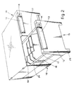
- The attached figures, which are given as a non-restrictive example, show the following:-
- Fig.1a
- gives a three-dimensional view of a modular cabinet according to the invention with two drawers;
- Fig.1b
- gives a three-dimensional front view of a plurality of different modular cabinets placed side by side and stacked one on another according to a desired usage arrangement;
- Fig.2
- shows the cabinet of Fig.1a with a drawer partly pulled out;
- Fig.3
- shows the cabinet of Fig.1 with a drawer fully extracted;
- Fig.4a
- shows a partial, vertical cross section of the cabinet of Fig.1;
- Fig.4b
- shows a vertical, lengthwise section of a drawer according to Fig.1;
- Fig.5
- shows the system for fitting the window which gives information regarding the contents;
- Fig.6
- shows a possible system for fitting a lock;
- Figs.7a
- and 7b shows a lengthwise, vertical section and a vertical cross section of another drawer, which can be installed side by side with two other drawers in one single modular cabinet;
- Figs.8a
- and 8b show a drawer which can be installed by itself alone in a cabinet.
- In the figures a
modular cabinet 10 comprises a containingcase 39 made by combining two half-cases 11 on a horizontal plane; the two half-cases 11 are clamped to each other by a plurality of male-female anchorage assemblies 29 located on the periphery and on the inside of each containingcase 39 of themodular cabinet 10. - The
case 39 of the cabinet comprises at its front an opening equipped withmeans 19 to limit extraction which serve to limit the extraction ofdrawers 12; these extraction limiting means 19 serve also to provide closure by means of alock 14. - In the lower part of the containing
case 39 are locatedreinforcement plates 23 to which are fittedslide blocks 22 that serve to guide thedrawers 12 and to simplify and speed up their sliding movement. Theseslide blocks 22 may consist of individual elements or one single element along an edge and have a substantially h-shaped conformation. - A containing
case 39 can cooperate with one single drawer 12 (Figs.8a and 8b) or with two (Figs. 4a and 4b) or three drawers (Figs.7a and 7b) or more. - In the combination example of Fig.1b modular cabinets are shown with one, two and three drawers for each
modular cabinet 10. - The
modular cabinet 10 may have a constant height for each type, namely for each number of drawers provided, or may have two heights according to the number and dimensions of the drawers. The example of Fig.1b showsmodular cabinets 10 of two different heights. - A
front panel 20 of thedrawers 12 comprises on its front side anouter front handle 15,feet 25, anupper display window 13 which can be read from the front or from above and alock 14. - A
drawer 12 may comprise at its front an auxiliary structural-reinforcement element 43, which may or may not be removable. - As said above, the
drawer 12 comprises afront panel 20 and arear closure panel 21, therear closure panel 21 being able to abut against the extraction limiting means 19 during extraction of thedrawer 12. - Each
drawer 12 comprises awell 38, which may be plain without any special equipment, as in Fig.8a for instance, or have its bottom specially equipped withmovable partitions 18 which can be fitted when desired. - A
drawer 12 cooperates advantageously withinternal handles 17 which comprise apivot 32 capable of being anchored inholes 31. - The
holes 31 are conformed and positioned (Figs.4 and 7) to suit the geometric characteristics of thedrawers 12 so as to enable theinternal handles 17 to be standardized. -
Reinforcement plates 44 are included in cooperation with theholes 31 and serve to reinforce theholes 31 and to position theinternal handles 17. - The
internal handles 17 are able to take up a lateral position (Fig.2) for lateral retention of the contents of the drawer and an extraction position corresponding with a central position (Fig.3) able to prevent vertical departure of the contents and, at the same time, to enable anindividual drawer 12 to be handled independently. - Appropriate lateral 42 and central 142 positioning ribs are included on the inner side of the
front panel 20 andrear closure panel 21 in cooperation with the well 38 so as to improve the services of the half-handles andhandle 17 respectively. - When
modular cabinets 10 are combined with each other,slider clips 28 for clamping purposes are applied to connectingholes 16 provided on the upper and lower lateral edges of thecase 39 and can couple together two, three or fourmodular cabinets 10 at the same time. - Positioner holes 33 cooperating with the
movable partitions 18 are located in the well 38 of thedrawers 12. - The
movable partitions 18 include advantageously a raisedindicator portion 24 and also jutting side portions on each side which are able to cooperate withsurfaces 41 of edges of the well 38. - The bottom of the well 38 comprises
holes 33 and alsolateral positioner dividers 30 for correct positioning of the contents. - The
display window 13 comprises an L-shapedwindow body 36 made of a transparent material to create ancontainment chamber 40 in which the required information can be inserted. - The conformation of the
chamber 40 enables the information contained therein to be read on the upper and front surfaces of thechamber 40. - A
lock 14 comprises adisplay body 35 that cooperates with abolt 27, which includes at its front anentry 34 for a key and cooperates with theextraction limiting means 19. - The
window body 36 of thedisplay window 13 and thedisplay body 35 of thelock 14 are clamped in position by reciprocal deformation of their parts. - The
drawers 12 comprise continuouslateral slide paths 37 which cooperate with the replaceable slide blocks 22.
Claims (6)
- Modular cabinet which comprises a cabinet case (39) and at least one extractable drawer (12) and can be combined with other cabinets, whereby it includes at least one drawer with a front panel (20) and a rear closure panel (21), the panels being connected by a well (38) having edges (41), the front panel having a lower central outer handle (15), characterized in that:
each of said at least one drawer (12) comprises two (inner) handles (17) which can take up an individual lateral position and a combined central position in cooperation with said well (38);
the front aperture of said cabinet case (39) comprises means (19) for limiting the extraction of said at least one drawer (12), said means (19) abutting against said rear closure panel (21) and in that
each of said at least one drawer (12) is provided with individual key-operated locking means (14) cooperating with said limiting means (19) comprised in said front aperture of said cabinet case (39). - Modular cabinet (10) as claimed in Claim 1, in which the inner handles (17) cooperate with holes (31) or with lateral (42) and central (142) positioner ribs.
- Modular cabinet (10) as claimed in any claim hereinbefore, in which the bottom of the well (38) comprises positioner holes (33) and lateral positioner dividers (30) laterally and lengthwise.
- Modular cabinet (10) as claimed in Claim 3, in which modular partitions (18) having a raised indicator portion (24) and jutting side portions cooperating with edges (41) of the well (38) cooperate with the positioner holes (33).
- Modular cabinet (10) as claimed in any claim hereinbefore, in which the cabinet case (39) comprises two half-cases (11) coupled by a plurality of anchorage assemblies (29) on the horizontal plane.
- Modular cabinet (10) as claimed in any claim hereinbefore, in which the cabinet case (39) comprises at its sides coordinated coupling holes (16) cooperating with clamping clips (28) during assembly of cabinets.
Priority Applications (1)
| Application Number | Priority Date | Filing Date | Title |
|---|---|---|---|
| AT88105367T ATE68324T1 (en) | 1987-07-21 | 1988-04-02 | CABINET MODULE. |
Applications Claiming Priority (2)
| Application Number | Priority Date | Filing Date | Title |
|---|---|---|---|
| IT8760412U IT218570Z2 (en) | 1987-07-21 | 1987-07-21 | MODULAR CONTAINER. |
| IT6041287U | 1987-07-21 |
Publications (2)
| Publication Number | Publication Date |
|---|---|
| EP0300134A1 EP0300134A1 (en) | 1989-01-25 |
| EP0300134B1 true EP0300134B1 (en) | 1991-10-16 |
Family
ID=11290857
Family Applications (1)
| Application Number | Title | Priority Date | Filing Date |
|---|---|---|---|
| EP88105367A Expired - Lifetime EP0300134B1 (en) | 1987-07-21 | 1988-04-02 | Modular cabinet |
Country Status (8)
| Country | Link |
|---|---|
| US (1) | US4856855A (en) |
| EP (1) | EP0300134B1 (en) |
| AT (1) | ATE68324T1 (en) |
| CA (1) | CA1310684C (en) |
| DE (1) | DE3865564D1 (en) |
| ES (1) | ES2022047T3 (en) |
| GR (1) | GR3003190T3 (en) |
| IT (1) | IT218570Z2 (en) |
Families Citing this family (10)
| Publication number | Priority date | Publication date | Assignee | Title |
|---|---|---|---|---|
| US5358321A (en) * | 1993-01-04 | 1994-10-25 | Fellowes Manufacturing Company | Modular multi-media cabinet |
| US5651456A (en) * | 1994-12-06 | 1997-07-29 | Gunning; John D. | Multi-media storage system |
| US5667287A (en) * | 1995-04-21 | 1997-09-16 | Gunning; John D. | Multi-media storage system having a multi-component insert assembly |
| SE515769C2 (en) | 2000-02-29 | 2001-10-08 | System Edstroem Bilinredningar | The cassette is designed for the construction of box closets |
| US20020185941A1 (en) | 2001-06-11 | 2002-12-12 | Ferraro Frank A. | Moving cart assemblies |
| FR2873272B1 (en) * | 2004-07-22 | 2006-09-29 | Yves Mallouk | MODULAR STORAGE AND STORAGE ASSEMBLY |
| DE202013100137U1 (en) * | 2013-01-11 | 2014-01-31 | Tielsa Gmbh | Furniture front of a furniture line |
| JP5858488B2 (en) * | 2013-07-04 | 2016-02-10 | 株式会社伸和 | Storage case |
| CN105397760A (en) * | 2015-12-14 | 2016-03-16 | 苏州源硕精密模具有限公司 | Sleeve with terminals convenient to take out |
| USD790884S1 (en) * | 2016-02-29 | 2017-07-04 | Ronbow Corporation | Vanity base with seat |
Family Cites Families (15)
| Publication number | Priority date | Publication date | Assignee | Title |
|---|---|---|---|---|
| US394377A (en) * | 1888-12-11 | Type-writer cabinet | ||
| US2667392A (en) * | 1950-07-08 | 1954-01-26 | Sexton Can Co Inc | Table with detachable box |
| US3203744A (en) * | 1962-12-12 | 1965-08-31 | Ethicon Inc | Cabinet assembly unit |
| DE1911175U (en) * | 1964-12-10 | 1965-03-04 | Fritz Schaefer Kommanditgesell | SHELVING FOR STORAGE BOXES. |
| DE1951853A1 (en) * | 1966-08-31 | 1971-05-06 | Ekkehard Meyer | closet |
| US3499695A (en) | 1968-01-17 | 1970-03-10 | Lyon Metal Products Inc | Drawer and compressor plate construction |
| US3751127A (en) * | 1970-09-10 | 1973-08-07 | Telecommunication Technology I | Modular instrument housing |
| US3909078A (en) * | 1973-04-02 | 1975-09-30 | Martin O Riley | Drawer assembly |
| FR2355481A1 (en) * | 1975-12-29 | 1978-01-20 | Ferodo Sa | Plastics furniture modules for wall units - are of frontally open box and drawer chest form and are built from identical half-boxes joined by clips and bolted stiffeners |
| US4245715A (en) * | 1979-08-06 | 1981-01-20 | Litton Systems, Inc. | Automatic drive prevention |
| WO1982001810A1 (en) * | 1980-11-24 | 1982-06-10 | Long Jerry M | Diskette filing and storage container |
| US4501456A (en) * | 1981-03-31 | 1985-02-26 | Fritz Schafer Gesellschaft Mit Beschrankterhaftung | Storage rack with multiple drawer compartments and mold for making same |
| US4512480A (en) * | 1983-08-11 | 1985-04-23 | Eldon Industries, Inc. | Article holding device |
| US4624509A (en) * | 1983-10-11 | 1986-11-25 | Myers Industries | Storage drawer |
| US4634193A (en) * | 1984-12-21 | 1987-01-06 | Mike Liu | Cabinet for storing small parts such as bolts screws or the like |
-
1987
- 1987-07-21 IT IT8760412U patent/IT218570Z2/en active
-
1988
- 1988-04-02 AT AT88105367T patent/ATE68324T1/en not_active IP Right Cessation
- 1988-04-02 EP EP88105367A patent/EP0300134B1/en not_active Expired - Lifetime
- 1988-04-02 DE DE8888105367T patent/DE3865564D1/en not_active Expired - Lifetime
- 1988-04-02 ES ES198888105367T patent/ES2022047T3/en not_active Expired - Lifetime
- 1988-04-08 CA CA000563717A patent/CA1310684C/en not_active Expired - Lifetime
- 1988-04-15 US US07/182,136 patent/US4856855A/en not_active Expired - Fee Related
-
1991
- 1991-11-25 GR GR91401806T patent/GR3003190T3/en unknown
Also Published As
| Publication number | Publication date |
|---|---|
| IT218570Z2 (en) | 1992-06-17 |
| DE3865564D1 (en) | 1991-11-21 |
| CA1310684C (en) | 1992-11-24 |
| ATE68324T1 (en) | 1991-11-15 |
| GR3003190T3 (en) | 1993-02-17 |
| US4856855A (en) | 1989-08-15 |
| EP0300134A1 (en) | 1989-01-25 |
| ES2022047A4 (en) | 1991-12-01 |
| ES2022047T3 (en) | 1992-06-01 |
Similar Documents
| Publication | Publication Date | Title |
|---|---|---|
| US4616890A (en) | Medication carts and cassettes | |
| US4856855A (en) | Modular cabinet | |
| US20210267368A1 (en) | Storage Device | |
| US5437502A (en) | Utility holder | |
| CA2246991C (en) | Inclined slide assemblies for vertical drawers | |
| EP0162999A1 (en) | Container for magnetic tape cassettes or the like | |
| US4728200A (en) | Extension pull-out guide assembly for drawers | |
| US6619770B1 (en) | Security drawer for service cart | |
| US3575480A (en) | Interlocking arrangement | |
| US3490824A (en) | Sliding door construction | |
| US5761786A (en) | Method of retrofitting a sliding drawer within an existing cabinet | |
| USRE34171E (en) | Medication carts and cassettes | |
| US2758744A (en) | Sliding and pivoting closure for receptacle | |
| US3527515A (en) | In-wall identification label mounting for catalogue card trays and the like | |
| EP0482337B1 (en) | Workshop magazine | |
| US4645074A (en) | System for the organized storage of a plurality of record carriers | |
| US4598958A (en) | Pull-out drawer for a filing case | |
| EP1870546A1 (en) | Anti-theft display container | |
| CA3091745A1 (en) | Lockout box | |
| US4111504A (en) | Storage file and retrieval system | |
| DE1131026B (en) | Storage container for records and other flat objects | |
| US3254930A (en) | Vertical filing cabinet with fixed or movable compartments for standing or hanging up the folders therein | |
| EP0836193A1 (en) | A modular container for the storage of computer media | |
| JP3473326B2 (en) | Cabinet installation structure | |
| US2865700A (en) | Utility cabinet for a business machine |
Legal Events
| Date | Code | Title | Description |
|---|---|---|---|
| PUAI | Public reference made under article 153(3) epc to a published international application that has entered the european phase |
Free format text: ORIGINAL CODE: 0009012 |
|
| AK | Designated contracting states |
Kind code of ref document: A1 Designated state(s): AT BE CH DE ES FR GB GR IT LI LU NL SE |
|
| 17P | Request for examination filed |
Effective date: 19890613 |
|
| 17Q | First examination report despatched |
Effective date: 19900816 |
|
| GRAA | (expected) grant |
Free format text: ORIGINAL CODE: 0009210 |
|
| ITF | It: translation for a ep patent filed | ||
| AK | Designated contracting states |
Kind code of ref document: B1 Designated state(s): AT BE CH DE ES FR GB GR IT LI LU NL SE |
|
| REF | Corresponds to: |
Ref document number: 68324 Country of ref document: AT Date of ref document: 19911115 Kind code of ref document: T |
|
| REF | Corresponds to: |
Ref document number: 3865564 Country of ref document: DE Date of ref document: 19911121 |
|
| ET | Fr: translation filed | ||
| REG | Reference to a national code |
Ref country code: ES Ref legal event code: FG2A Ref document number: 2022047 Country of ref document: ES Kind code of ref document: T3 |
|
| PLBI | Opposition filed |
Free format text: ORIGINAL CODE: 0009260 |
|
| 26 | Opposition filed |
Opponent name: NEW TECHNOLOGY DEVELOPMENT S.R.L. Effective date: 19920713 |
|
| REG | Reference to a national code |
Ref country code: GR Ref legal event code: FG4A Free format text: 3003190 |
|
| NLR1 | Nl: opposition has been filed with the epo |
Opponent name: NEW TECHNOLOGY DEVELOPMENT S.R.L. |
|
| PGFP | Annual fee paid to national office [announced via postgrant information from national office to epo] |
Ref country code: LU Payment date: 19930324 Year of fee payment: 6 |
|
| PGFP | Annual fee paid to national office [announced via postgrant information from national office to epo] |
Ref country code: GR Payment date: 19930331 Year of fee payment: 6 |
|
| PGFP | Annual fee paid to national office [announced via postgrant information from national office to epo] |
Ref country code: BE Payment date: 19930414 Year of fee payment: 6 |
|
| PGFP | Annual fee paid to national office [announced via postgrant information from national office to epo] |
Ref country code: CH Payment date: 19930504 Year of fee payment: 6 |
|
| PGFP | Annual fee paid to national office [announced via postgrant information from national office to epo] |
Ref country code: ES Payment date: 19930603 Year of fee payment: 6 |
|
| EPTA | Lu: last paid annual fee | ||
| PLBN | Opposition rejected |
Free format text: ORIGINAL CODE: 0009273 |
|
| STAA | Information on the status of an ep patent application or granted ep patent |
Free format text: STATUS: OPPOSITION REJECTED |
|
| 27O | Opposition rejected |
Effective date: 19930715 |
|
| NLR2 | Nl: decision of opposition | ||
| PG25 | Lapsed in a contracting state [announced via postgrant information from national office to epo] |
Ref country code: LU Free format text: LAPSE BECAUSE OF NON-PAYMENT OF DUE FEES Effective date: 19940402 |
|
| PG25 | Lapsed in a contracting state [announced via postgrant information from national office to epo] |
Ref country code: ES Free format text: LAPSE BECAUSE OF NON-PAYMENT OF DUE FEES Effective date: 19940404 |
|
| PG25 | Lapsed in a contracting state [announced via postgrant information from national office to epo] |
Ref country code: LI Effective date: 19940430 Ref country code: CH Effective date: 19940430 Ref country code: BE Effective date: 19940430 |
|
| BERE | Be: lapsed |
Owner name: SEIMA ITALIANA S.P.A. Effective date: 19940430 |
|
| PG25 | Lapsed in a contracting state [announced via postgrant information from national office to epo] |
Ref country code: GR Free format text: THE PATENT HAS BEEN ANNULLED BY A DECISION OF A NATIONAL AUTHORITY Effective date: 19941031 |
|
| REG | Reference to a national code |
Ref country code: CH Ref legal event code: PL |
|
| EAL | Se: european patent in force in sweden |
Ref document number: 88105367.2 |
|
| ITPR | It: changes in ownership of a european patent |
Owner name: CESSIONE;EXPONENT ITALIA S.R.L. |
|
| REG | Reference to a national code |
Ref country code: GR Ref legal event code: MM2A Free format text: 3003190 |
|
| REG | Reference to a national code |
Ref country code: FR Ref legal event code: TP |
|
| REG | Reference to a national code |
Ref country code: GB Ref legal event code: 732E |
|
| NLS | Nl: assignments of ep-patents |
Owner name: EXPONENT ITALIANA SPA |
|
| PGFP | Annual fee paid to national office [announced via postgrant information from national office to epo] |
Ref country code: GB Payment date: 19970324 Year of fee payment: 10 |
|
| PGFP | Annual fee paid to national office [announced via postgrant information from national office to epo] |
Ref country code: FR Payment date: 19970326 Year of fee payment: 10 |
|
| PGFP | Annual fee paid to national office [announced via postgrant information from national office to epo] |
Ref country code: DE Payment date: 19970408 Year of fee payment: 10 |
|
| PGFP | Annual fee paid to national office [announced via postgrant information from national office to epo] |
Ref country code: SE Payment date: 19970423 Year of fee payment: 10 |
|
| PGFP | Annual fee paid to national office [announced via postgrant information from national office to epo] |
Ref country code: NL Payment date: 19970430 Year of fee payment: 10 Ref country code: AT Payment date: 19970430 Year of fee payment: 10 |
|
| PG25 | Lapsed in a contracting state [announced via postgrant information from national office to epo] |
Ref country code: GB Free format text: LAPSE BECAUSE OF NON-PAYMENT OF DUE FEES Effective date: 19980402 Ref country code: AT Free format text: LAPSE BECAUSE OF NON-PAYMENT OF DUE FEES Effective date: 19980402 |
|
| PG25 | Lapsed in a contracting state [announced via postgrant information from national office to epo] |
Ref country code: SE Free format text: LAPSE BECAUSE OF NON-PAYMENT OF DUE FEES Effective date: 19980403 |
|
| PG25 | Lapsed in a contracting state [announced via postgrant information from national office to epo] |
Ref country code: FR Free format text: THE PATENT HAS BEEN ANNULLED BY A DECISION OF A NATIONAL AUTHORITY Effective date: 19980430 |
|
| PG25 | Lapsed in a contracting state [announced via postgrant information from national office to epo] |
Ref country code: NL Free format text: LAPSE BECAUSE OF NON-PAYMENT OF DUE FEES Effective date: 19981101 |
|
| GBPC | Gb: european patent ceased through non-payment of renewal fee |
Effective date: 19980402 |
|
| NLV4 | Nl: lapsed or anulled due to non-payment of the annual fee |
Effective date: 19981101 |
|
| EUG | Se: european patent has lapsed |
Ref document number: 88105367.2 |
|
| PG25 | Lapsed in a contracting state [announced via postgrant information from national office to epo] |
Ref country code: DE Free format text: LAPSE BECAUSE OF NON-PAYMENT OF DUE FEES Effective date: 19990202 |
|
| REG | Reference to a national code |
Ref country code: FR Ref legal event code: ST |
|
| REG | Reference to a national code |
Ref country code: ES Ref legal event code: FD2A Effective date: 19990201 |
|
| PG25 | Lapsed in a contracting state [announced via postgrant information from national office to epo] |
Ref country code: IT Free format text: LAPSE BECAUSE OF NON-PAYMENT OF DUE FEES;WARNING: LAPSES OF ITALIAN PATENTS WITH EFFECTIVE DATE BEFORE 2007 MAY HAVE OCCURRED AT ANY TIME BEFORE 2007. THE CORRECT EFFECTIVE DATE MAY BE DIFFERENT FROM THE ONE RECORDED. Effective date: 20050402 |