EP0298518B1 - Method for manufacturing a copper-clad steel trolley wire - Google Patents
Method for manufacturing a copper-clad steel trolley wire Download PDFInfo
- Publication number
- EP0298518B1 EP0298518B1 EP88110982A EP88110982A EP0298518B1 EP 0298518 B1 EP0298518 B1 EP 0298518B1 EP 88110982 A EP88110982 A EP 88110982A EP 88110982 A EP88110982 A EP 88110982A EP 0298518 B1 EP0298518 B1 EP 0298518B1
- Authority
- EP
- European Patent Office
- Prior art keywords
- copper
- wire
- steel wire
- steel
- alloy
- Prior art date
- Legal status (The legal status is an assumption and is not a legal conclusion. Google has not performed a legal analysis and makes no representation as to the accuracy of the status listed.)
- Expired - Lifetime
Links
- 229910000831 Steel Inorganic materials 0.000 title claims description 116
- 239000010959 steel Substances 0.000 title claims description 116
- 238000000034 method Methods 0.000 title claims description 26
- 238000004519 manufacturing process Methods 0.000 title claims description 14
- RYGMFSIKBFXOCR-UHFFFAOYSA-N Copper Chemical compound [Cu] RYGMFSIKBFXOCR-UHFFFAOYSA-N 0.000 claims description 63
- 229910052802 copper Inorganic materials 0.000 claims description 60
- 239000010949 copper Substances 0.000 claims description 60
- 229910000881 Cu alloy Inorganic materials 0.000 claims description 49
- 229910052751 metal Inorganic materials 0.000 claims description 18
- 239000002184 metal Substances 0.000 claims description 18
- 238000005096 rolling process Methods 0.000 claims description 11
- OKTJSMMVPCPJKN-UHFFFAOYSA-N Carbon Chemical compound [C] OKTJSMMVPCPJKN-UHFFFAOYSA-N 0.000 claims description 9
- 229910052799 carbon Inorganic materials 0.000 claims description 8
- 230000002093 peripheral effect Effects 0.000 claims description 8
- 238000005098 hot rolling Methods 0.000 claims description 6
- 239000010410 layer Substances 0.000 description 49
- 239000002131 composite material Substances 0.000 description 22
- 238000005260 corrosion Methods 0.000 description 16
- 230000007797 corrosion Effects 0.000 description 16
- 230000000052 comparative effect Effects 0.000 description 10
- 239000000463 material Substances 0.000 description 7
- 238000003780 insertion Methods 0.000 description 4
- 230000037431 insertion Effects 0.000 description 4
- 238000012360 testing method Methods 0.000 description 4
- XEEYBQQBJWHFJM-UHFFFAOYSA-N Iron Chemical compound [Fe] XEEYBQQBJWHFJM-UHFFFAOYSA-N 0.000 description 3
- 238000005299 abrasion Methods 0.000 description 3
- 229910052782 aluminium Inorganic materials 0.000 description 3
- XAGFODPZIPBFFR-UHFFFAOYSA-N aluminium Chemical compound [Al] XAGFODPZIPBFFR-UHFFFAOYSA-N 0.000 description 3
- 229910001209 Low-carbon steel Inorganic materials 0.000 description 2
- 239000004411 aluminium Substances 0.000 description 2
- 238000000137 annealing Methods 0.000 description 2
- 238000005452 bending Methods 0.000 description 2
- IYRDVAUFQZOLSB-UHFFFAOYSA-N copper iron Chemical compound [Fe].[Cu] IYRDVAUFQZOLSB-UHFFFAOYSA-N 0.000 description 2
- 238000009713 electroplating Methods 0.000 description 2
- 238000007654 immersion Methods 0.000 description 2
- 230000000149 penetrating effect Effects 0.000 description 2
- 229910052718 tin Inorganic materials 0.000 description 2
- XLYOFNOQVPJJNP-UHFFFAOYSA-N water Substances O XLYOFNOQVPJJNP-UHFFFAOYSA-N 0.000 description 2
- ATJFFYVFTNAWJD-UHFFFAOYSA-N Tin Chemical compound [Sn] ATJFFYVFTNAWJD-UHFFFAOYSA-N 0.000 description 1
- 229910045601 alloy Inorganic materials 0.000 description 1
- 239000000956 alloy Substances 0.000 description 1
- 230000015572 biosynthetic process Effects 0.000 description 1
- 229910052804 chromium Inorganic materials 0.000 description 1
- 239000011247 coating layer Substances 0.000 description 1
- 238000010276 construction Methods 0.000 description 1
- 238000001816 cooling Methods 0.000 description 1
- 238000010586 diagram Methods 0.000 description 1
- 230000000694 effects Effects 0.000 description 1
- 238000011156 evaluation Methods 0.000 description 1
- 229910002804 graphite Inorganic materials 0.000 description 1
- 239000010439 graphite Substances 0.000 description 1
- 238000011835 investigation Methods 0.000 description 1
- 229910052742 iron Inorganic materials 0.000 description 1
- 238000005259 measurement Methods 0.000 description 1
- 238000002844 melting Methods 0.000 description 1
- 230000008018 melting Effects 0.000 description 1
- 239000000203 mixture Substances 0.000 description 1
- 229910052698 phosphorus Inorganic materials 0.000 description 1
- 239000011819 refractory material Substances 0.000 description 1
- 230000001105 regulatory effect Effects 0.000 description 1
- 229910052709 silver Inorganic materials 0.000 description 1
- 239000002344 surface layer Substances 0.000 description 1
- 229910052726 zirconium Inorganic materials 0.000 description 1
Images

Classifications
-
- B—PERFORMING OPERATIONS; TRANSPORTING
- B60—VEHICLES IN GENERAL
- B60M—POWER SUPPLY LINES, AND DEVICES ALONG RAILS, FOR ELECTRICALLY- PROPELLED VEHICLES
- B60M1/00—Power supply lines for contact with collector on vehicle
- B60M1/12—Trolley lines; Accessories therefor
- B60M1/13—Trolley wires
- B60M1/135—Trolley wires composite
Definitions
- the present invention relates to a method for manufacturing a copper-clad steel trolley wire, which comprises a steel core wire and a copper or copper-alloy layer covering the peripheral surface of the core.
- the wave propagation velocity of the trolley wires should be increased in advance.
- the wave propagation velocity C can be increased by heightening the tension T or by lowering the linear density ⁇ .
- an aluminum-composite trolley wire is proposed as a trolley wire with lower linear density ⁇ and higher propagation velocity C.
- This wire is composed of a steel wire and an aluminum covering layer pressure-bonded thereto.
- metal fixtures currently used therefor are made of copper alloy, so that galvanic corrosion may be caused between the metal fixtures and the aluminium covering layer of the trolley wire. Such corrosion can be avoided only by forming the metal fixtures from a material which cannot suffer galvanic corrosion with aluminium. This countermeasure is not practical, however, in view of cost performance.
- a composite trolley wire which combines a copper-based material and an iron-based material of higher strength than copper is disclosed in document DE-C-536 656.
- the copper layer is welded or soldered to the iron core in a manner which is not described in detail and the composite wire is than rolled such that an elongate cross section is obtained.
- a copper coated steel wire is scalped to form a copper coated core wire which is thereafter passed through a copper path for forming a copper coating layer and than subjected to rolling and cooling.
- the rolling conditions are not specified in detail.
- the copper-clad steel trolley wire manufactured by the method of the present invention uses the steel wire as a core it can enjoy high strength and wiring tension. Thus, with use of this trolley wire, the travelling speed of electric trains can be increased.
- the trolley wire is high in wear resistance.
- the trolley wire can be installed directly by means of conventional metal fixtures. Also, the trolley wire can enjoy a required electrical conductivity (50 % IACS or more).
- the steel wire, as the core, and the copper or copper-alloy region, as the covering layer are metallurgically bonded to each other, so that corrosion cannot advance at the boundary between the core and the covering layer.
- the boundary is exposed, for example, water or the like can be prevented from penetrating the boundary.
- the covering layer can be restrained from being separated from the core at the boundary between them.
- the covering layer and the core can be bonded with sufficient strength.
- the steel wire, as the core is immersed in the molten copper or copper alloy so that the molten metal adheres to the peripheral surface of the steel wire when it is solidified.
- the cast rod is obtained which is composed of a copper-clad steel wire covered by copper or copper alloy.
- the steel wire, as the core, and the copper or copper-alloy region, as the covering layer are metallurgically bonded to each other, so that the core and the covering layer are firmly bonded to each other.
- high bonding strength can be obtained between the core and the covering layer, and corrosion can be prevented from advancing at the boundary between the core and the covering layer.
- the steel wire is covered with copper or copper alloy by being immersed in molten copper or molten copper alloy.
- a composite wire rod having a large diameter and a thick covering layer thereon, like a trolley wire, can be manufactured at lower cost than by the electroplating method or the like.
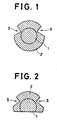
- Fig. 1 is a sectional view of a copper-clad steel trolley wire manufactured by the method of the present invention, as taken along the diameter thereof.
- the trolley wire has a core 1 formed of a steel wire in its central portion.
- the core 1 is covered by covering layer 2 with a substantially uniform thickness, except the regions corresponding to fitting grooves 3.
- the covering layer 2 is formed of copper or copper alloy, and a pair of V-shaped grooves 3 are formed on the peripheral surface of the covering layer 2 so as to extend in the longitudinal direction of the trolley wire.
- the grooves 3 are held by means of metal fixtures (not shown), whereby the trolley wire is suspended.
- the steel wire is used as the core 1 in order to improve the wear resistance of the trolley wire, as well as its strength. Any type of steel may be used for the steel wire. If the strength of the steel wire is too high, however, the trolley wire will be awkward to handle during its manufacturing processes or wiring work. Preferably, therefore, the material of the steel wire should have a carbon content of 0.35 % or less by weight. If the carbon content is higher than 0.35 % by weight, then the strength of the steel wire is so high that the life of a shaving die is shortened during the manufacturing processes for the composite wire by the so-called dip forming method, for example.
- the copper or copper alloy is used as the covering layer 2 in order to secure the required electrical conductivity of the trolley wire and to prevent galvanic corrosion with the metal fixtures.
- the covering layer 2 formed of copper or copper alloy, occupies 45 to 75 % of the cross-sectional area of the whole copper-clad steel trolley wire.
- the covering rate of the covering layer 2 is 45 % or less, its thickness is smaller than the predetermined depth of the grooves 3 cut in the composite wire. As a result, the steel core 1 is exposed through the grooves 3. If the covering rate of the covering layer 2 exceeds 75 %, the core portion naturally becomes so small that the improvement efficiency of the wear resistance is reduced. Thus, the covering rate of the covering layer 2 is adjusted to 45 to 75 % in terms of the cross-sectional area ratio (ratio of the cross-sectional area of the covering layer to that of the whole trolley wire).
- this copper-clad steel composite wire As a trolley wire, its electrical conductivity should be 50 % IACS (compared with 100 % for the conductivity of annealed pure copper) or more. Accordingly, the various conditions, including the types of steel and copper or copper alloy, the covering rate, etc., should be selected so that the conductivity is 50 % or more.
- the aforesaid copper alloy may be one which contains at least one of those elements including Ag, Zr, Cr, Sn, and P, at about 0.3 % by weight.
- the heat resistance of the covering layer 2 can be improved by the use of such a copper alloy.
- the present invention is characterized in that the steel wire, as the core 1, and the copper or copper-alloy region, as the covering layer 2, are metallurgically bonded to each other.
- a steel wire is immersed in molten copper or molten copper alloy by the so-called dip forming method, for example, and the resulting copper-clad cast rod is hot-rolled.
- the thickness of the covering layer 2 can be regulated by adjusting the time of immersion of the steel wire in molten copper.
- the covering layer is metallurgically bonded to the core
- atoms diffuse at the interface between the steel wire and the copper or copper-alloy region, thereby ensuring very strong bonding. Therefore, even if a compressive load is applied to the composite wire in the diametrical direction thereof, for example, the steel wire and the copper or copper-alloy region cannot be separated from each other. This also applies to a case such that the composite wire is subjected to tensile fracture stress or bending stress.
- the steel wire If the steel wire is exposed, it is corroded so that the trolley wire wears slightly. The degree of such wear, however, is lower than that of wear of the trolley wire which is attributable to abrasion and sparking caused by the slide of pantographs. On those railroad lines which are subject to much traffic or high-frequency passage of the pantographs, in particular, the wear of the trolley wire is mainly due to the abrasion and sparking, and the duration of the trolley wire is influenced little by the corrosion of the steel wire.
- the copper-clad steel trolley wire thus constructed, is covered by the copper or copper-alloy covering layer 2 with the predetermined covering rate, so that the covering layer 2 touches the metal fixtures that are used to suspend the trolley wire.
- galvanic corrosion cannot be caused between the metal fixtures, made of copper alloy, and the trolley wire.
- the steel wire is used as the core 1, moreover, the trolley wire is high in strength and wear resistance. If the strength of the trolley wire is thus high, then the wiring tension T can be set to a high value. In consequence, the wave propagation velocity C can be increased, as mentioned before, to permit high-speed traveling of electric trains.
- the bonding strength is high, and the covering layer 2 cannot be peeled off at the bonding interface even when bending stress is applied to the trolley wire. Even if the trolley wire is worn away so that the core 1 is exposed, moreover, the bonding interface is not corroded selectively.
- a so-called dip forming apparatus used in the aforementioned embodiment of the present invention will be described.
- a copper or copper-alloy covering unit 20 is disposed over a wire feeder unit 10.
- An airtight housing 11 of the feeder unit 10 is provided with an exhaust port 15, which is coupled to a suitable vacuum exhaust unit (not shown).
- the inside of the housing 11 is evacuated through the exhaust port 15 to be kept at a predetermined degree of vacuum.
- the shaving die 12 is located at a wire inlet of the lateral wall of the housing 11. The steel wire 4 is fed through this inlet into the housing 11, and its outermost surface layer is cut off by means of the shaving die 12.
- a capstan 13 is set in the housing 11, and the steel wire 4 is wound around the capstan 13 to be pulled and redirected upward thereby.
- Two pairs of pinch rollers 16 are arranged inside the upper portion of the housing 11. The steel wire 4 is driven to be drawn out by means of the pinch rollers 16 so that it is fed from the housing 11 into the covering unit 20.
- a straightening unit 14 for correcting a bend of the steel wire 4 is disposed in that region inside the housing 11 between the pinch rollers 16 and the capstan 13.
- the straightening unit 14 includes two rollers 14a and 14c, adapted to roll on the inside of the steel wire 4 bent by the capstan 13, and a roller 14b rollable on the outside of the steel wire between the rollers 14a and 14c.
- the steel wire 4 fed from the capstan 13 is brought into rolling contact with the rollers 14a, 14b and 14c in succession, whereby its bend, produced by the capstan 13, is corrected.
- the rollers 14a, 14b and 14c may be rotated positively by means of a suitable drive unit (not shown) or be driven like an idler only by the steel wire 4.
- the distances between the rollers 14a, 14b and 14c can be adjusted depending on the type of the steel wire, the degree of the bend, etc.
- the covering unit 20 includes a crucible 22 which is stored with the molten copper or copper alloy 21.
- the crucible 22, which is made of refractory material such as graphite, is coupled to the housing 11 of the feeder unit 10 in a manner such that the top outlet of the housing 11 is closed airtight by the outer bottom surface of the crucible 22.
- the crucible 22 is formed, at its bottom portion, with an insertion aperture 23 having a little larger diameter than the steel wire 4.
- the steel wire 4 is introduced into the crucible 22 through the aperture 23, in a liquid-tight manner.
- a molten metal feed port 24, which is formed in the flank of the crucible 22, is connected to a copper or copper-alloy melting unit 30.
- the molten metal 21 is fed into the crucible 22 through the feed port 24.
- a wire draw-out unit (not shown) is disposed above the covering unit 20.
- the composite cast rod 5 is delivered from the covering unit 20 to a hot-rolling apparatus (not shown) in the next stage.
- the steel wire is covered with copper or copper alloy by using the dip forming apparatus of the aforementioned construction, and the resulting composite wire is then hot-rolled.
- the steel wire 4 is fed into the evacuated housing 11 while its outermost layer is being continuously cut off by the shaving die 12, as shown in Fig. 3. Having its surface cleaned in this manner, the steel wire 4 is passed around the capstan 13 to change its course upward. Although the steel wire 4 is thus bent by the capstan 13, it is straightened by means of the rollers 14a, 14b and 14c of the straightening unit 14.
- the steel wire 4 is drawn out upward by means of the pinch rollers 16, and is introduced into the crucible 22 through the insertion aperture 23 at the bottom portion of the crucible. Then, the steel wire 4 is drawn out upward through the crucible 22 so that the molten metal 21 in the crucible adheres to the steel wire in the meantime. The adhered molten metal 21 solidifies, thereby completing the composite cast rod 5 which is composed of the steel wire 4 having copper or copper alloy on the peripheral surface thereof.
- the composite cast rod 5 is then hot-rolled at a temperature of 750 to 850 °C and with a rolling ratio of 10 to 40 %, by means of the hot-rolling apparatus.
- the steel wire, as the core, and the copper or copper-alloy region, as the covering layer are coupled metal to metal, that is, the covering layer is metallurgically bonded on the core.
- the rolling ratio used is lower than 10 %, the steel wire and the copper or copper-alloy region cannot be bonded satisfactorily. If the ratio is higher than 40 %, on the other hand, the degree of working is too high to obtain a uniform thickness of the copper or copper-alloy covering layer. According to the present invention, the rolling ratio is set within the range of 10 to 40 % for those reasons.
- the rolling temperature range of 750 to 850 °C is used in order to ensure strong metallurgical bonding and to facilitate the rolling work with the aforementioned rolling ratio.
- the composite wire is drawn and grooved. More specifically, a pair of V-shaped grooves 3 are formed on the copper or copper-alloy covering layer 2 which covers the steel core 1, as shown in the sectional view of Fig. 1. Thus, the trolley wire is completed.
- the steel wire is covered with copper or copper alloy by the so-called dip forming method, so that the copper-clad steel trolley wire can be manufactured at low cost.
- the trolley wire is composed mainly of a thick wire rod with a diameter of 10 mm or more, and the covering layer (copper or copper alloy) must be formed thick enough for the formation of the wiring grooves.
- the covering layer by electroplating or the like, therefore, the cost of manufacture of the copper-clad steel wire is very high.
- the composite wire for the trolley wire can be manufactured at low cost.
- the steel wire 4 having been passed around the capstan 13 and bent, are straightened by means of the rollers 14a, 14b and 14c of the straightening unit 14.
- a conventional dip forming apparatus for copper wire is not provided with such a straightening unit.
- the steel wire 4 Since the steel wire 4 is harder than a copper wire, it positively bends when it is passed around the capstan 13. The bend cannot be corrected by only pulling the steel wire 4 by means of the pinch rollers 16. Thus, the steel wire 4 may possibly be caught by the insertion aperture 23 of the crucible 22, thereby interrupting the operation. In the present embodiment, however, the steel wire 4 is straightened by means of the three rollers 14a, 14b and 14c, it can be fed steadily into the crucible 22 without jamming or interference at the aperture 23.
- the core was formed from a mild steel wire rod JISG-3505/SWRM-10 (14-mm diameter) of the composition shown in Table 1.
- this mild steel wire rod was removed by means of the shaving die 12, and a core wire with a diameter of 12.7 mm was obtained.
- This core wire was straightened by means of the straightening unit 14, and was then delivered to the covering unit 20.
- the bend length was able to be restricted to about 3 to 10 mm in a section of 1,000-mm length.
- the straightening unit 14 was not used, on the other hand, the steel core wire bent for a length of about 40 to 60 mm in the 1,000-mm section, thus failing to be passed through the insertion aperture 23 with stability.
- Example 1 in which a covering rate of 45 % is used, for example, a copper-clad steel cast rod with a diameter of 17 mm was manufactured by covering the peripheral surface of the steel core wire 4 with copper by means of the covering unit 20, based on the dip forming method. Then, the cast rod was hot-rolled (30 % rolling ratio) to obtain a composite wire with a diameter of 14.5 mm. By this hot rolling, the steel core wire and the copper region were metallurgically bonded to each other.
- the covering rate of the copper covering layer can be varied by adjusting the immersion time for the steel wire in the crucible 22 and the like. Thus, a copper covering layer of a required thickness can be formed.
- Comparative Examples 1 and 2 were manufactured in the same manner as Examples 1 to 3. However, the copper volume ratio (covering rate) of Comparative Example 1 is as low as 40 %, while that of Comparative Example 2 is as high as 80 %.
- the trolley wires of Prior Art Examples 1, 2 and 3 are a copper wire, copper-alloy wire, and aluminum-clad steel wire, respectively.
- the cross-sectional area of the trolley wire of Prior Art Example 3 is 200 mm2, while that of the other trolley wires is 110 mm2.
- each trolley wire is as high as 50 kgf/mm2 or more, and the steel core and the copper covering layer are firmly metallurgically bonded to each other.
- the trolley wires of these examples have high galvanic resistance.
- the trolley wires of Examples 1 to 3 moreover, have high electrical conductivity of 50 % IACS or more, and are high in wear resistance. It was ascertained that if the copper covering layer is worn away so that the steel core starts to be exposed, the trolley wire cannot easily wear any more. Since the trolley wire can be installed with use of conventional metal fixtures, furthermore, its fixture mounting capability is high.
- Comparative Example 1 in contrast with this, the covering rate is as low as 40 %, so that the electrical conductivity is as low as 45 %. Thus, the steel may possibly be exposed through the grooves to suffer galvanic corrosion, that is, the fixture mounting capability is low. In Comparative Example 2, moreover, the covering rate is so high as 80 % that the steel wire portion is too small to produce the effect of improvement of the wear resistance. Thus, the wear resistance of Comparative Example 2 is not high enough.
- both the strength and the wear resistance are low.
- the aluminum-clad steel trolley wire of Prior Art Example 3 is also low in strength, and besides, may suffer galvanic corrosion with copper-alloy fixtures, thus proving poor in fixture mounting capability.
- trolley wires of the above examples have the cross-sectional area of 110 mm2, it is to be understood that the present invention may be also applied to trolley wires of any other types, such as those with a cross-sectional area of 170 mm2.
- Table 3 shows the relationships between the type of steel of the steel wire, carbon content, evaluation of shaving capability, and steel wire strength (after annealing).
- Table 3 Type of Steel of Steel Wire Carbon Content (%) Shaving Capability Steel Wire Strength (kgf/mm2) SWRM-6 0.06 Good 38 SWRM-10 0.11 Good 45 SWRH-37 0.35 Good 55 SWRH-42A 0.40 Poor 60
- the shaving capability was evaluated as "Poor” when the duration of the shaving die 12 was shorter than 3 hours, and as "Good” when the die's duration is 3 hours or longer.
- the steel wire strength is so high that the duration of the shaving die 12 is short. Accordingly, the operation must be interrupted more frequently for the replacement of the die, thus entailing higher costs.
- the steel wire used should have a carbon content of 0.35 % or less by weight.
- an alloy wire or the like may be used, provided its strength after annealing is equal to that of the steel wire.
Landscapes
- Engineering & Computer Science (AREA)
- Mechanical Engineering (AREA)
- Coating With Molten Metal (AREA)
- Non-Insulated Conductors (AREA)
- Wire Processing (AREA)
Description
- The present invention relates to a method for manufacturing a copper-clad steel trolley wire, which comprises a steel core wire and a copper or copper-alloy layer covering the peripheral surface of the core.
- Conventionally, copper wires or copper alloy wires are used for railroad-use trolley wires. The electric trains of nowadays are positively expected to travel at high speed, so that the trolley wires are required to have improved strength.
- In order to increase the traveling speed of the electric trains, the wave propagation velocity of the trolley wires should be increased in advance. The wave propagation velocity C may be given by

where T is the wiring tension, and ρ is the linear density (weight per unit length) of a trolley wire. - As seen from equation (1), the wave propagation velocity C can be increased by heightening the tension T or by lowering the linear density ρ.
- Thereupon, an aluminum-composite trolley wire is proposed as a trolley wire with lower linear density ρ and higher propagation velocity C. This wire is composed of a steel wire and an aluminum covering layer pressure-bonded thereto.
- According to this conventional aluminum-composite trolley wire, however, metal fixtures currently used therefor are made of copper alloy, so that galvanic corrosion may be caused between the metal fixtures and the aluminium covering layer of the trolley wire. Such corrosion can be avoided only by forming the metal fixtures from a material which cannot suffer galvanic corrosion with aluminium. This countermeasure is not practical, however, in view of cost performance.
- A composite trolley wire which combines a copper-based material and an iron-based material of higher strength than copper is disclosed in document DE-C-536 656. The copper layer is welded or soldered to the iron core in a manner which is not described in detail and the composite wire is than rolled such that an elongate cross section is obtained.
- In this composite trolley wire composed of the iron- and copper-based materials, however, corrosion may be caused between the two materials, practically entailing a lot of problems. To prevent such corrosion, a lead or tin layer is interposed between the iron- and copper-based materials (see Japanese Patent Disclosure No. 53-122786). The interposition of such an intermediate layer would, however, lower the strength of the trolley wire, and require more complicated manufacturing processes.
- The method of manufacturing a composite trolley wire with increased corrosion resistance is described in Japanese Patent Application 62-30866. According to this method a copper coated steel wire is scalped to form a copper coated core wire which is thereafter passed through a copper path for forming a copper coating layer and than subjected to rolling and cooling. The rolling conditions are not specified in detail.
- It is further known from document DE-B-1269856 to manufacture a copper-clad-steel wire by first shaving of the outer steel layer of a steel core by means of a scalping die and thereafter passing the bare steel core through a copper bath.
- It is the object of the present invention to provide a method for manufacturing a copper-clad steel trolley wire, which is free from galvanic corrosion with metal fixtures, improved in wear resistance and corrosion resistance and having higher strength to permit higher wiring tension. This object is achieved according to the present invention by means of a manufacturing method as defined in claim 1.
- Since the copper-clad steel trolley wire manufactured by the method of the present invention uses the steel wire as a core it can enjoy high strength and wiring tension. Thus, with use of this trolley wire, the travelling speed of electric trains can be increased.
- Essentially composed of the steel wire, moreover, the trolley wire is high in wear resistance.
- Since the core is covered with the copper or copper-alloy covering layer preferably with a cross-sectional area ratio of 45 to 75 %, furthermore, galvanic corrosion with copper-alloy fixtures can be prevented. Thus, the trolley wire can be installed directly by means of conventional metal fixtures. Also, the trolley wire can enjoy a required electrical conductivity (50 % IACS or more).
- According to the present invention, moreover, the steel wire, as the core, and the copper or copper-alloy region, as the covering layer, are metallurgically bonded to each other, so that corrosion cannot advance at the boundary between the core and the covering layer. Thus, even if the boundary is exposed, for example, water or the like can be prevented from penetrating the boundary.
- Since the steel wire and the copper or copper-alloy are metallurgically bonded, furthermore, the covering layer can be restrained from being separated from the core at the boundary between them. Thus, the covering layer and the core can be bonded with sufficient strength.
- In the method for manufacturing a copper-clad steel trolley wire according to the present invention, the steel wire, as the core, is immersed in the molten copper or copper alloy so that the molten metal adheres to the peripheral surface of the steel wire when it is solidified. In this manner, the cast rod is obtained which is composed of a copper-clad steel wire covered by copper or copper alloy. When the cast rod is then hot-rolled under the predetermined conditions defined in claim 1, the steel wire, as the core, and the copper or copper-alloy region, as the covering layer, are metallurgically bonded to each other, so that the core and the covering layer are firmly bonded to each other. Thus, high bonding strength can be obtained between the core and the covering layer, and corrosion can be prevented from advancing at the boundary between the core and the covering layer.
- According to the present invention, moreover, the steel wire is covered with copper or copper alloy by being immersed in molten copper or molten copper alloy. By this method, a composite wire rod, having a large diameter and a thick covering layer thereon, like a trolley wire, can be manufactured at lower cost than by the electroplating method or the like.
- Fig. 1 is a sectional view of a copper-clad steel trolley wire manufactured by a method according to an embodiment of the present invention;
- Fig. 2 is a sectional view showing the trolley wire after abrasion; and
- Fig. 3 is a diagram showing a dip forming apparatus used in the method of the invention.
- Fig. 1 is a sectional view of a copper-clad steel trolley wire manufactured by the method of the present invention, as taken along the diameter thereof. The trolley wire has a core 1 formed of a steel wire in its central portion. The core 1 is covered by covering
layer 2 with a substantially uniform thickness, except the regions corresponding tofitting grooves 3. Thecovering layer 2 is formed of copper or copper alloy, and a pair of V-shaped grooves 3 are formed on the peripheral surface of thecovering layer 2 so as to extend in the longitudinal direction of the trolley wire. Thegrooves 3 are held by means of metal fixtures (not shown), whereby the trolley wire is suspended. - The steel wire is used as the core 1 in order to improve the wear resistance of the trolley wire, as well as its strength. Any type of steel may be used for the steel wire. If the strength of the steel wire is too high, however, the trolley wire will be awkward to handle during its manufacturing processes or wiring work. Preferably, therefore, the material of the steel wire should have a carbon content of 0.35 % or less by weight. If the carbon content is higher than 0.35 % by weight, then the strength of the steel wire is so high that the life of a shaving die is shortened during the manufacturing processes for the composite wire by the so-called dip forming method, for example.
- The copper or copper alloy is used as the covering
layer 2 in order to secure the required electrical conductivity of the trolley wire and to prevent galvanic corrosion with the metal fixtures. - The covering
layer 2, formed of copper or copper alloy, occupies 45 to 75 % of the cross-sectional area of the whole copper-clad steel trolley wire. - If the covering rate of the covering
layer 2 is 45 % or less, its thickness is smaller than the predetermined depth of thegrooves 3 cut in the composite wire. As a result, the steel core 1 is exposed through thegrooves 3. If the covering rate of the coveringlayer 2 exceeds 75 %, the core portion naturally becomes so small that the improvement efficiency of the wear resistance is reduced. Thus, the covering rate of the coveringlayer 2 is adjusted to 45 to 75 % in terms of the cross-sectional area ratio (ratio of the cross-sectional area of the covering layer to that of the whole trolley wire). - In order to use this copper-clad steel composite wire as a trolley wire, its electrical conductivity should be 50 % IACS (compared with 100 % for the conductivity of annealed pure copper) or more. Accordingly, the various conditions, including the types of steel and copper or copper alloy, the covering rate, etc., should be selected so that the conductivity is 50 % or more.
- The aforesaid copper alloy may be one which contains at least one of those elements including Ag, Zr, Cr, Sn, and P, at about 0.3 % by weight. The heat resistance of the covering
layer 2 can be improved by the use of such a copper alloy. - The present invention is characterized in that the steel wire, as the core 1, and the copper or copper-alloy region, as the covering
layer 2, are metallurgically bonded to each other. In a method for manufacturing a composite wire in which a covering layer is metallurgically bonded to a core, as described in detail later, a steel wire is immersed in molten copper or molten copper alloy by the so-called dip forming method, for example, and the resulting copper-clad cast rod is hot-rolled. The thickness of thecovering layer 2 can be regulated by adjusting the time of immersion of the steel wire in molten copper. - In the composite wire in which the covering layer is metallurgically bonded to the core, atoms diffuse at the interface between the steel wire and the copper or copper-alloy region, thereby ensuring very strong bonding. Therefore, even if a compressive load is applied to the composite wire in the diametrical direction thereof, for example, the steel wire and the copper or copper-alloy region cannot be separated from each other. This also applies to a case such that the composite wire is subjected to tensile fracture stress or bending stress.
- Accordingly, even if the trolley wire is worn away so that the steel core 1 is exposed, as shown in Fig. 2, water or the like can be prevented from penetrating the boundary between the core 1 and the copper or copper-
alloy covering layer 2. Thus, the boundary region cannot be corroded with priority. - If the steel wire is exposed, it is corroded so that the trolley wire wears slightly. The degree of such wear, however, is lower than that of wear of the trolley wire which is attributable to abrasion and sparking caused by the slide of pantographs. On those railroad lines which are subject to much traffic or high-frequency passage of the pantographs, in particular, the wear of the trolley wire is mainly due to the abrasion and sparking, and the duration of the trolley wire is influenced little by the corrosion of the steel wire.
- The copper-clad steel trolley wire, thus constructed, is covered by the copper or copper-
alloy covering layer 2 with the predetermined covering rate, so that thecovering layer 2 touches the metal fixtures that are used to suspend the trolley wire. Thus, galvanic corrosion cannot be caused between the metal fixtures, made of copper alloy, and the trolley wire. Since the steel wire is used as the core 1, moreover, the trolley wire is high in strength and wear resistance. If the strength of the trolley wire is thus high, then the wiring tension T can be set to a high value. In consequence, the wave propagation velocity C can be increased, as mentioned before, to permit high-speed traveling of electric trains. - Since the steel core 1 and the copper or copper-
alloy covering layer 2 are metallurgically bonded to each other, the bonding strength is high, and thecovering layer 2 cannot be peeled off at the bonding interface even when bending stress is applied to the trolley wire. Even if the trolley wire is worn away so that the core 1 is exposed, moreover, the bonding interface is not corroded selectively. - The following is a detailed description of the method for manufacturing the trolley wire constructed in the aforesaid manner. Referring first to Fig. 3, a so-called dip forming apparatus used in the aforementioned embodiment of the present invention will be described. In this dip forming apparatus, a copper or copper-
alloy covering unit 20 is disposed over awire feeder unit 10. - An airtight housing 11 of the
feeder unit 10 is provided with anexhaust port 15, which is coupled to a suitable vacuum exhaust unit (not shown). The inside of the housing 11 is evacuated through theexhaust port 15 to be kept at a predetermined degree of vacuum. The shaving die 12 is located at a wire inlet of the lateral wall of the housing 11. Thesteel wire 4 is fed through this inlet into the housing 11, and its outermost surface layer is cut off by means of the shaving die 12. - A
capstan 13 is set in the housing 11, and thesteel wire 4 is wound around thecapstan 13 to be pulled and redirected upward thereby. Two pairs ofpinch rollers 16 are arranged inside the upper portion of the housing 11. Thesteel wire 4 is driven to be drawn out by means of thepinch rollers 16 so that it is fed from the housing 11 into the coveringunit 20. - A straightening
unit 14 for correcting a bend of thesteel wire 4 is disposed in that region inside the housing 11 between thepinch rollers 16 and thecapstan 13. The straighteningunit 14 includes tworollers 14a and 14c, adapted to roll on the inside of thesteel wire 4 bent by thecapstan 13, and aroller 14b rollable on the outside of the steel wire between therollers 14a and 14c. Thesteel wire 4 fed from thecapstan 13 is brought into rolling contact with therollers capstan 13, is corrected. Therollers steel wire 4. The distances between therollers - The covering
unit 20 includes acrucible 22 which is stored with the molten copper orcopper alloy 21. Thecrucible 22, which is made of refractory material such as graphite, is coupled to the housing 11 of thefeeder unit 10 in a manner such that the top outlet of the housing 11 is closed airtight by the outer bottom surface of thecrucible 22. Thecrucible 22 is formed, at its bottom portion, with aninsertion aperture 23 having a little larger diameter than thesteel wire 4. Thus, thesteel wire 4 is introduced into thecrucible 22 through theaperture 23, in a liquid-tight manner. - A molten
metal feed port 24, which is formed in the flank of thecrucible 22, is connected to a copper or copper-alloy melting unit 30. Thus, themolten metal 21 is fed into thecrucible 22 through thefeed port 24. - A wire draw-out unit (not shown) is disposed above the covering
unit 20. Acomposite cast rod 5, which is composed of thesteel wire 4 covered by copper or copper alloy, is drawn out upward by means of the draw-out unit. Thecomposite cast rod 5 is delivered from the coveringunit 20 to a hot-rolling apparatus (not shown) in the next stage. - According to the embodiment of the present invention described above, the steel wire is covered with copper or copper alloy by using the dip forming apparatus of the aforementioned construction, and the resulting composite wire is then hot-rolled.
- First, the
steel wire 4 is fed into the evacuated housing 11 while its outermost layer is being continuously cut off by the shaving die 12, as shown in Fig. 3. Having its surface cleaned in this manner, thesteel wire 4 is passed around thecapstan 13 to change its course upward. Although thesteel wire 4 is thus bent by thecapstan 13, it is straightened by means of therollers unit 14. - Subsequently, the
steel wire 4 is drawn out upward by means of thepinch rollers 16, and is introduced into thecrucible 22 through theinsertion aperture 23 at the bottom portion of the crucible. Then, thesteel wire 4 is drawn out upward through thecrucible 22 so that themolten metal 21 in the crucible adheres to the steel wire in the meantime. The adheredmolten metal 21 solidifies, thereby completing thecomposite cast rod 5 which is composed of thesteel wire 4 having copper or copper alloy on the peripheral surface thereof. - The
composite cast rod 5 is then hot-rolled at a temperature of 750 to 850 °C and with a rolling ratio of 10 to 40 %, by means of the hot-rolling apparatus. Thereupon, the steel wire, as the core, and the copper or copper-alloy region, as the covering layer, are coupled metal to metal, that is, the covering layer is metallurgically bonded on the core. - If the rolling ratio used is lower than 10 %, the steel wire and the copper or copper-alloy region cannot be bonded satisfactorily. If the ratio is higher than 40 %, on the other hand, the degree of working is too high to obtain a uniform thickness of the copper or copper-alloy covering layer. According to the present invention, the rolling ratio is set within the range of 10 to 40 % for those reasons. The rolling temperature range of 750 to 850 °C is used in order to ensure strong metallurgical bonding and to facilitate the rolling work with the aforementioned rolling ratio.
- After the hot rolling, the composite wire is drawn and grooved. More specifically, a pair of V-shaped
grooves 3 are formed on the copper or copper-alloy covering layer 2 which covers the steel core 1, as shown in the sectional view of Fig. 1. Thus, the trolley wire is completed. - According to the present embodiment, the steel wire is covered with copper or copper alloy by the so-called dip forming method, so that the copper-clad steel trolley wire can be manufactured at low cost. The trolley wire is composed mainly of a thick wire rod with a diameter of 10 mm or more, and the covering layer (copper or copper alloy) must be formed thick enough for the formation of the wiring grooves. When forming the covering layer by electroplating or the like, therefore, the cost of manufacture of the copper-clad steel wire is very high. In contrast with this, if the copper or the copper-alloy layer is formed by the dip forming method, as in the case of the present embodiment, the composite wire for the trolley wire can be manufactured at low cost.
- In the present embodiment, the
steel wire 4, having been passed around thecapstan 13 and bent, are straightened by means of therollers unit 14. A conventional dip forming apparatus for copper wire is not provided with such a straightening unit. When dip-forming the steel wire, as in the case of this embodiment, it is difficult to introduce the steel wire smoothly into thecrucible 22 without the use of the straighteningunit 14. - Since the
steel wire 4 is harder than a copper wire, it positively bends when it is passed around thecapstan 13. The bend cannot be corrected by only pulling thesteel wire 4 by means of thepinch rollers 16. Thus, thesteel wire 4 may possibly be caught by theinsertion aperture 23 of thecrucible 22, thereby interrupting the operation. In the present embodiment, however, thesteel wire 4 is straightened by means of the threerollers crucible 22 without jamming or interference at theaperture 23. - The following is a description of the test results of examples of the copper-clad steel trolley wire according to the present invention, compared with the results of tests on comparative examples and prior art trolley wires.
- In the trolley wires of the examples and the comparative examples, the core was formed from a mild steel wire rod JISG-3505/SWRM-10 (14-mm diameter) of the composition shown in Table 1.

- The outermost layer portion of this mild steel wire rod was removed by means of the shaving die 12, and a core wire with a diameter of 12.7 mm was obtained. This core wire was straightened by means of the straightening
unit 14, and was then delivered to the coveringunit 20. In this case, when the distances between therollers unit 14 was not used, on the other hand, the steel core wire bent for a length of about 40 to 60 mm in the 1,000-mm section, thus failing to be passed through theinsertion aperture 23 with stability. - According to Example 1 in which a covering rate of 45 % is used, for example, a copper-clad steel cast rod with a diameter of 17 mm was manufactured by covering the peripheral surface of the
steel core wire 4 with copper by means of the coveringunit 20, based on the dip forming method. Then, the cast rod was hot-rolled (30 % rolling ratio) to obtain a composite wire with a diameter of 14.5 mm. By this hot rolling, the steel core wire and the copper region were metallurgically bonded to each other. - Subsequently, the wire was drawn into a wire rod with a diameter of 13.1 mm, and was then grooved. Thus, a trolley wire having the cross-sectional shape shown in Fig. 1 and a cross-sectional area of 110 mm² was completed. The trolley wires of Examples 2 and 3 and Comparative Examples 1 and 2, having different covering rates, were manufactured in the same manner as the trolley wire of Example 1.
- The covering rate of the copper covering layer can be varied by adjusting the immersion time for the steel wire in the
crucible 22 and the like. Thus, a copper covering layer of a required thickness can be formed. - The electrical conductivity and tensile strength of these trolley wires were measured. Also, the exposure of steel, fixture mounting capability, and wear resistance were tested on the trolley wires. Table 2 shows the results of these measurements and tests, along with test results for the prior art trolley wires.
Table 2 Copper Ratio (%) Conductivity (% IACS) Tensile Strength (kgf/mm²) Exposure of Steel at Grooves Fixture Mounting Capability Wear Resistance Example 1 45 50 70 None Good Good 2 55 60 65 None Good Good 3 75 77 50 None Good Good Comparative Example 1 40 45 75 Some Poor Good 2 80 81 47 None Good Moderate Prior Art Example 1 100 100 35 None Good Poor 2 100 75 40 None Good Moderate 3 - 49 24 None Poor Good - Comparative Examples 1 and 2 were manufactured in the same manner as Examples 1 to 3. However, the copper volume ratio (covering rate) of Comparative Example 1 is as low as 40 %, while that of Comparative Example 2 is as high as 80 %. The trolley wires of Prior Art Examples 1, 2 and 3 are a copper wire, copper-alloy wire, and aluminum-clad steel wire, respectively. The cross-sectional area of the trolley wire of Prior Art Example 3 is 200 mm², while that of the other trolley wires is 110 mm².
- In Examples 1 to 3, the tensile strength of each trolley wire is as high as 50 kgf/mm² or more, and the steel core and the copper covering layer are firmly metallurgically bonded to each other. Thus, the trolley wires of these examples have high galvanic resistance. The trolley wires of Examples 1 to 3, moreover, have high electrical conductivity of 50 % IACS or more, and are high in wear resistance. It was ascertained that if the copper covering layer is worn away so that the steel core starts to be exposed, the trolley wire cannot easily wear any more. Since the trolley wire can be installed with use of conventional metal fixtures, furthermore, its fixture mounting capability is high.
- In Comparative Example 1, in contrast with this, the covering rate is as low as 40 %, so that the electrical conductivity is as low as 45 %. Thus, the steel may possibly be exposed through the grooves to suffer galvanic corrosion, that is, the fixture mounting capability is low. In Comparative Example 2, moreover, the covering rate is so high as 80 % that the steel wire portion is too small to produce the effect of improvement of the wear resistance. Thus, the wear resistance of Comparative Example 2 is not high enough.
- In the copper trolley wire and the copper-alloy trolley wire of Prior Art Examples 1 and 2, both the strength and the wear resistance are low. The aluminum-clad steel trolley wire of Prior Art Example 3 is also low in strength, and besides, may suffer galvanic corrosion with copper-alloy fixtures, thus proving poor in fixture mounting capability.
- Although the trolley wires of the above examples have the cross-sectional area of 110 mm², it is to be understood that the present invention may be also applied to trolley wires of any other types, such as those with a cross-sectional area of 170 mm².
- The following is a description of the results of an investigation on the relationship between the type of steel of the steel wire and the duration of the shaving die. Table 3 shows the relationships between the type of steel of the steel wire, carbon content, evaluation of shaving capability, and steel wire strength (after annealing).
Table 3 Type of Steel of Steel Wire Carbon Content (%) Shaving Capability Steel Wire Strength (kgf/mm²) SWRM-6 0.06 Good 38 SWRM-10 0.11 Good 45 SWRH-37 0.35 Good 55 SWRH-42A 0.40 Poor 60
The shaving capability was evaluated as "Poor" when the duration of the shaving die 12 was shorter than 3 hours, and as "Good" when the die's duration is 3 hours or longer. As seen from Table 3, if the carbon content is higher than 0.35 % by weight (SWRH-42A), the steel wire strength is so high that the duration of the shaving die 12 is short. Accordingly, the operation must be interrupted more frequently for the replacement of the die, thus entailing higher costs. Preferably, therefore, the steel wire used should have a carbon content of 0.35 % or less by weight. - Instead of using the steel wire with the carbon content of 0.35 % or less by weight, an alloy wire or the like may be used, provided its strength after annealing is equal to that of the steel wire.
Claims (6)
- A method for manufacturing a copper-clad steel trolley wire comprising:
a process for continuously immersing a steel wire (4) in molten copper or molten copper alloy (21) and then solidifying the copper or copper alloy to cause the same to adhere to the peripheral surface of said steel wire, thereby obtaining a cast rod (5) consisting essentially of said steel wire and copper or copper alloy layer covering the peripheral surface of said steel wire; and
a process for hot-rolling said cast rod (5) at a temperature of 750 to 850 oC and with a rolling ratio of 10 to 40 %. - The method according to claim 1, characterized in that the carbon content of said steel wire (1,4) is 0.35 % or less by weight.
- The method according to claim 1, characterized in that the cross-sectional area of the copper or copper-alloy region ranges from 45 to 75 % of that of the copper-clad steel trolley wire after said hot rolling.
- The method according to claim 1, characterized in that said steel wire (4) is immersed in molten copper or molten-copper alloy after being straightened.
- The method according to claim 4, characterized in that said steel wire (4) is immersed in molten copper or molten-copper alloy (21) after the outermost layer of said steel wire is cut off by means of a shaving die (12).
- The method according to claim 4 or 5, characterized in that said straightened steel wire is introduced into a vessel (22), containing molten copper or molten-copper alloy (21), through the bottom portion thereof, so that said molten metal adheres to the peripheral surface of said steel wire while said steel wire is being drawn up in said vessel.
Applications Claiming Priority (4)
| Application Number | Priority Date | Filing Date | Title |
|---|---|---|---|
| JP62171252A JP2633570B2 (en) | 1987-07-10 | 1987-07-10 | Copper coated steel trolley wire |
| JP171252/87 | 1987-07-10 | ||
| JP17336087A JPS6418737A (en) | 1987-07-11 | 1987-07-11 | Manufacture of copper coated steel trolley wire |
| JP173360/87 | 1987-07-11 |
Publications (3)
| Publication Number | Publication Date |
|---|---|
| EP0298518A2 EP0298518A2 (en) | 1989-01-11 |
| EP0298518A3 EP0298518A3 (en) | 1989-05-03 |
| EP0298518B1 true EP0298518B1 (en) | 1993-03-31 |
Family
ID=26494045
Family Applications (1)
| Application Number | Title | Priority Date | Filing Date |
|---|---|---|---|
| EP88110982A Expired - Lifetime EP0298518B1 (en) | 1987-07-10 | 1988-07-08 | Method for manufacturing a copper-clad steel trolley wire |
Country Status (4)
| Country | Link |
|---|---|
| EP (1) | EP0298518B1 (en) |
| CN (1) | CN1011681B (en) |
| DE (1) | DE3879782T2 (en) |
| ES (1) | ES2041744T3 (en) |
Cited By (3)
| Publication number | Priority date | Publication date | Assignee | Title |
|---|---|---|---|---|
| US9044056B2 (en) | 2012-05-08 | 2015-06-02 | Willis Electric Co., Ltd. | Modular tree with electrical connector |
| US9055777B2 (en) | 2010-09-23 | 2015-06-16 | Willis Electric Co., Ltd. | Modular artificial lighted tree with decorative light string |
| US9157588B2 (en) | 2013-09-13 | 2015-10-13 | Willis Electric Co., Ltd | Decorative lighting with reinforced wiring |
Families Citing this family (15)
| Publication number | Priority date | Publication date | Assignee | Title |
|---|---|---|---|---|
| AU635306B2 (en) * | 1989-09-01 | 1993-03-18 | Fujikura Ltd. | High-conductivity copper-clad steel trolley wire and a method for manufacturing the same |
| DE4435402A1 (en) * | 1994-10-04 | 1996-04-11 | Thyssen Draht Ag | Process for the surface coating of profile wires |
| CN1046185C (en) * | 1994-11-18 | 1999-11-10 | 张星辰 | Acetic acid, glutaminic acid and copper ammoniate bactericidal agent and its preparing method |
| DE19627612A1 (en) * | 1996-07-09 | 1998-01-15 | Alcatel Kabel Ag | Method for producing a contact wire for the power supply of electrically powered vehicles |
| RU2195730C2 (en) * | 2000-06-23 | 2002-12-27 | Закрытое акционерное общество "Уралтранс" | Method for reinforcing overhead contact wire |
| RU2261185C2 (en) * | 2003-10-01 | 2005-09-27 | Открытое акционерное общество "Каменск-Уральский завод по обработке цветных металлов" | Contact wire |
| CN103042950A (en) * | 2012-11-20 | 2013-04-17 | 大连通发新材料开发有限公司 | Copper-coated steel strand carrier cable |
| CN102963270A (en) * | 2012-11-26 | 2013-03-13 | 大连通发新材料开发有限公司 | Copper-clad steel wire dropper for contact network |
| EP2808873A1 (en) * | 2013-05-28 | 2014-12-03 | Nexans | Electrically conductive wire and method for its manufacture |
| US9140438B2 (en) | 2013-09-13 | 2015-09-22 | Willis Electric Co., Ltd. | Decorative lighting with reinforced wiring |
| CN105118569B (en) * | 2015-09-22 | 2017-03-08 | 山东理工职业学院 | A kind of Electric trolley wire |
| CA2946387A1 (en) | 2015-10-26 | 2017-04-26 | Willis Electric Co., Ltd. | Tangle-resistant decorative lighting assembly |
| EP3610416B1 (en) * | 2017-04-11 | 2022-02-16 | NV Bekaert SA | Rfid tag |
| CN111676476B (en) * | 2020-06-02 | 2022-03-15 | 江西瑞曼增材科技有限公司 | Method for preparing copper-chromium-zirconium slideway by laser 3D printing technology |
| CN114082801B (en) * | 2021-11-22 | 2024-01-02 | 昆明理工大学 | A continuous semi-solid forming method and device for copper-clad steel composite materials |
Family Cites Families (4)
| Publication number | Priority date | Publication date | Assignee | Title |
|---|---|---|---|---|
| DE536656C (en) * | 1929-08-02 | 1931-10-24 | Ver Deutsche Metallwerke Akt G | Profiled contact line, especially for electric railways |
| AT149028B (en) * | 1934-11-06 | 1937-03-25 | Otto Dipl Ing Kobold | Contact wire. |
| DE1269856B (en) * | 1960-09-12 | 1968-06-06 | Gen Electric | Method and device for applying a firmly adhering thick copper layer to metallic wire or rod material in a molten manner |
| DE149063T1 (en) * | 1983-12-30 | 1985-10-24 | Gte Products Corp., Wilmington, Del. | CONTINUOUS PLATING OF IRON ALLOYS WITH MOLTEN COPPER. |
-
1988
- 1988-07-08 EP EP88110982A patent/EP0298518B1/en not_active Expired - Lifetime
- 1988-07-08 DE DE19883879782 patent/DE3879782T2/en not_active Expired - Fee Related
- 1988-07-08 ES ES88110982T patent/ES2041744T3/en not_active Expired - Lifetime
- 1988-07-09 CN CN 88104339 patent/CN1011681B/en not_active Expired
Non-Patent Citations (1)
| Title |
|---|
| PATENT ABSTRACTS OF JAPAN, unexamined applications, section C, vol. 11, no. 214, July 10, 1987; THE PATENT OFFICE JAPANESE GOVERNMENT, page 14/C 434Kokai-no. 62-30 866 (FUJIKURA LTD) * |
Cited By (4)
| Publication number | Priority date | Publication date | Assignee | Title |
|---|---|---|---|---|
| US9055777B2 (en) | 2010-09-23 | 2015-06-16 | Willis Electric Co., Ltd. | Modular artificial lighted tree with decorative light string |
| US9044056B2 (en) | 2012-05-08 | 2015-06-02 | Willis Electric Co., Ltd. | Modular tree with electrical connector |
| US9526286B2 (en) | 2012-05-08 | 2016-12-27 | Willis Electric Co., Ltd. | Modular tree with electrical connector |
| US9157588B2 (en) | 2013-09-13 | 2015-10-13 | Willis Electric Co., Ltd | Decorative lighting with reinforced wiring |
Also Published As
| Publication number | Publication date |
|---|---|
| DE3879782D1 (en) | 1993-05-06 |
| EP0298518A2 (en) | 1989-01-11 |
| CN1030550A (en) | 1989-01-25 |
| CN1011681B (en) | 1991-02-20 |
| EP0298518A3 (en) | 1989-05-03 |
| DE3879782T2 (en) | 1993-08-12 |
| ES2041744T3 (en) | 1993-12-01 |
Similar Documents
| Publication | Publication Date | Title |
|---|---|---|
| EP0298518A2 (en) | Method for manufacturing a copper-clad steel trolley wire | |
| US5223349A (en) | Copper clad aluminum composite wire | |
| JP3718617B2 (en) | Porous electrode wire for electrical discharge machining | |
| US4156500A (en) | Method and apparatus for producing copper clad steel wire | |
| EP0415328B1 (en) | A method for manufacturing a high-conductivity copper-clad steel trolley wire | |
| US9255311B2 (en) | Copper alloy conductor, and trolley wire and cable using same, and copper alloy conductor fabrication method | |
| US4537642A (en) | Method of manufacturing Al-stabilized superconductor | |
| CA1312126C (en) | Copper-glad steel trolley wire and a method for manufacturing the same | |
| JP2004137551A (en) | Method for producing copper alloy conductor for train line and copper alloy conductor for train line | |
| JPH04370613A (en) | Electric contact material and its manufacture | |
| KR102640504B1 (en) | plated spear | |
| JP2633570B2 (en) | Copper coated steel trolley wire | |
| JPH07106412B2 (en) | High conductivity copper coated steel trolley wire manufacturing method | |
| JP3219916B2 (en) | Plating solid wire for arc welding | |
| JPH06240426A (en) | High-strength copper alloy trolley wire manufacturing method | |
| JPH06228680A (en) | Copper alloy wire and manufacturing method thereof | |
| JP2000119833A (en) | Hot-dip Sn-Zn plated steel sheet for electrical components | |
| JPS5910522B2 (en) | copper coated aluminum wire | |
| JP2713350B2 (en) | Electrode wire for wire electric discharge machining | |
| JPS6047344B2 (en) | Hot-dipped ultrafine copper alloy conductor | |
| JPH0211460B2 (en) | ||
| Tyler | Wrought copper and copper alloy products | |
| JPH0551715A (en) | Coating with fused zinc aluminum alloy plating with excellent fatigue properties | |
| JP2001180337A (en) | Copper alloy coated steel trolley wire and its manufacturing method | |
| JPH1096036A (en) | High strength and high conductivity copper alloy wire rod |
Legal Events
| Date | Code | Title | Description |
|---|---|---|---|
| PUAI | Public reference made under article 153(3) epc to a published international application that has entered the european phase |
Free format text: ORIGINAL CODE: 0009012 |
|
| AK | Designated contracting states |
Kind code of ref document: A2 Designated state(s): CH DE ES FR GB LI |
|
| PUAL | Search report despatched |
Free format text: ORIGINAL CODE: 0009013 |
|
| AK | Designated contracting states |
Kind code of ref document: A3 Designated state(s): CH DE ES FR GB LI |
|
| 17P | Request for examination filed |
Effective date: 19890518 |
|
| 17Q | First examination report despatched |
Effective date: 19910515 |
|
| RTI1 | Title (correction) | ||
| GRAA | (expected) grant |
Free format text: ORIGINAL CODE: 0009210 |
|
| AK | Designated contracting states |
Kind code of ref document: B1 Designated state(s): CH DE ES FR GB LI |
|
| REF | Corresponds to: |
Ref document number: 3879782 Country of ref document: DE Date of ref document: 19930506 |
|
| ET | Fr: translation filed | ||
| REG | Reference to a national code |
Ref country code: ES Ref legal event code: FG2A Ref document number: 2041744 Country of ref document: ES Kind code of ref document: T3 |
|
| PLBE | No opposition filed within time limit |
Free format text: ORIGINAL CODE: 0009261 |
|
| STAA | Information on the status of an ep patent application or granted ep patent |
Free format text: STATUS: NO OPPOSITION FILED WITHIN TIME LIMIT |
|
| 26N | No opposition filed | ||
| REG | Reference to a national code |
Ref country code: GB Ref legal event code: IF02 |
|
| PGFP | Annual fee paid to national office [announced via postgrant information from national office to epo] |
Ref country code: DE Payment date: 20040802 Year of fee payment: 17 |
|
| PGFP | Annual fee paid to national office [announced via postgrant information from national office to epo] |
Ref country code: GB Payment date: 20040805 Year of fee payment: 17 |
|
| PGFP | Annual fee paid to national office [announced via postgrant information from national office to epo] |
Ref country code: FR Payment date: 20040819 Year of fee payment: 17 |
|
| PGFP | Annual fee paid to national office [announced via postgrant information from national office to epo] |
Ref country code: CH Payment date: 20040824 Year of fee payment: 17 |
|
| PGFP | Annual fee paid to national office [announced via postgrant information from national office to epo] |
Ref country code: ES Payment date: 20040826 Year of fee payment: 17 |
|
| PG25 | Lapsed in a contracting state [announced via postgrant information from national office to epo] |
Ref country code: GB Free format text: LAPSE BECAUSE OF NON-PAYMENT OF DUE FEES Effective date: 20050708 |
|
| PG25 | Lapsed in a contracting state [announced via postgrant information from national office to epo] |
Ref country code: ES Free format text: LAPSE BECAUSE OF NON-PAYMENT OF DUE FEES Effective date: 20050709 |
|
| PG25 | Lapsed in a contracting state [announced via postgrant information from national office to epo] |
Ref country code: LI Free format text: LAPSE BECAUSE OF NON-PAYMENT OF DUE FEES Effective date: 20050731 Ref country code: CH Free format text: LAPSE BECAUSE OF NON-PAYMENT OF DUE FEES Effective date: 20050731 |
|
| PG25 | Lapsed in a contracting state [announced via postgrant information from national office to epo] |
Ref country code: DE Free format text: LAPSE BECAUSE OF NON-PAYMENT OF DUE FEES Effective date: 20060201 |
|
| REG | Reference to a national code |
Ref country code: CH Ref legal event code: PL |
|
| GBPC | Gb: european patent ceased through non-payment of renewal fee |
Effective date: 20050708 |
|
| PG25 | Lapsed in a contracting state [announced via postgrant information from national office to epo] |
Ref country code: FR Free format text: LAPSE BECAUSE OF NON-PAYMENT OF DUE FEES Effective date: 20060331 |
|
| REG | Reference to a national code |
Ref country code: FR Ref legal event code: ST Effective date: 20060331 |
|
| REG | Reference to a national code |
Ref country code: ES Ref legal event code: FD2A Effective date: 20050709 |