EP0298162B1 - Method and apparatus for precipitation of scale-forming materials from solution - Google Patents
Method and apparatus for precipitation of scale-forming materials from solution Download PDFInfo
- Publication number
- EP0298162B1 EP0298162B1 EP87305956A EP87305956A EP0298162B1 EP 0298162 B1 EP0298162 B1 EP 0298162B1 EP 87305956 A EP87305956 A EP 87305956A EP 87305956 A EP87305956 A EP 87305956A EP 0298162 B1 EP0298162 B1 EP 0298162B1
- Authority
- EP
- European Patent Office
- Prior art keywords
- chamber
- solution
- baffles
- scale
- outlet end
- Prior art date
- Legal status (The legal status is an assumption and is not a legal conclusion. Google has not performed a legal analysis and makes no representation as to the accuracy of the status listed.)
- Expired - Lifetime
Links
- 239000000463 material Substances 0.000 title claims description 32
- 238000000034 method Methods 0.000 title claims description 22
- 238000001556 precipitation Methods 0.000 title description 7
- QPLDLSVMHZLSFG-UHFFFAOYSA-N Copper oxide Chemical compound [Cu]=O QPLDLSVMHZLSFG-UHFFFAOYSA-N 0.000 claims abstract description 48
- 229960004643 cupric oxide Drugs 0.000 claims abstract description 24
- 239000007789 gas Substances 0.000 claims abstract description 15
- 238000002386 leaching Methods 0.000 claims abstract description 11
- 239000002002 slurry Substances 0.000 claims abstract description 10
- 230000001376 precipitating effect Effects 0.000 claims abstract description 9
- 238000001704 evaporation Methods 0.000 claims abstract description 7
- 238000009835 boiling Methods 0.000 claims abstract description 6
- 238000004821 distillation Methods 0.000 claims description 62
- QGZKDVFQNNGYKY-UHFFFAOYSA-N Ammonia Chemical compound N QGZKDVFQNNGYKY-UHFFFAOYSA-N 0.000 claims description 18
- CURLTUGMZLYLDI-UHFFFAOYSA-N Carbon dioxide Chemical compound O=C=O CURLTUGMZLYLDI-UHFFFAOYSA-N 0.000 claims description 16
- 239000002244 precipitate Substances 0.000 claims description 13
- 238000010438 heat treatment Methods 0.000 claims description 12
- 229910002092 carbon dioxide Inorganic materials 0.000 claims description 8
- XLYOFNOQVPJJNP-UHFFFAOYSA-N water Chemical compound O XLYOFNOQVPJJNP-UHFFFAOYSA-N 0.000 claims description 8
- RYGMFSIKBFXOCR-UHFFFAOYSA-N Copper Chemical compound [Cu] RYGMFSIKBFXOCR-UHFFFAOYSA-N 0.000 claims description 6
- 229910052802 copper Inorganic materials 0.000 claims description 6
- 239000010949 copper Substances 0.000 claims description 6
- 229910021529 ammonia Inorganic materials 0.000 claims description 5
- 239000001569 carbon dioxide Substances 0.000 claims description 4
- 230000004044 response Effects 0.000 claims description 4
- 230000009471 action Effects 0.000 abstract description 9
- 238000005201 scrubbing Methods 0.000 abstract description 6
- 150000004649 carbonic acid derivatives Chemical class 0.000 abstract description 5
- 229910044991 metal oxide Inorganic materials 0.000 abstract description 5
- 150000004706 metal oxides Chemical class 0.000 abstract description 5
- 238000000227 grinding Methods 0.000 abstract description 4
- -1 cupric oxide Chemical class 0.000 abstract 1
- 238000002156 mixing Methods 0.000 description 6
- 239000000203 mixture Substances 0.000 description 6
- 229910001868 water Inorganic materials 0.000 description 6
- 239000007788 liquid Substances 0.000 description 5
- 238000011084 recovery Methods 0.000 description 5
- 229910000069 nitrogen hydride Inorganic materials 0.000 description 4
- 230000008569 process Effects 0.000 description 4
- 230000004888 barrier function Effects 0.000 description 3
- 239000000919 ceramic Substances 0.000 description 3
- 239000011819 refractory material Substances 0.000 description 3
- 239000007787 solid Substances 0.000 description 3
- PXHVJJICTQNCMI-UHFFFAOYSA-N Nickel Chemical compound [Ni] PXHVJJICTQNCMI-UHFFFAOYSA-N 0.000 description 2
- 229910000831 Steel Inorganic materials 0.000 description 2
- 238000013459 approach Methods 0.000 description 2
- 230000000712 assembly Effects 0.000 description 2
- 238000000429 assembly Methods 0.000 description 2
- 230000008901 benefit Effects 0.000 description 2
- 230000008020 evaporation Effects 0.000 description 2
- 238000012423 maintenance Methods 0.000 description 2
- 230000014759 maintenance of location Effects 0.000 description 2
- 239000002184 metal Substances 0.000 description 2
- 229910052751 metal Inorganic materials 0.000 description 2
- 150000002739 metals Chemical class 0.000 description 2
- VUZPPFZMUPKLLV-UHFFFAOYSA-N methane;hydrate Chemical compound C.O VUZPPFZMUPKLLV-UHFFFAOYSA-N 0.000 description 2
- 230000006911 nucleation Effects 0.000 description 2
- 238000010899 nucleation Methods 0.000 description 2
- 239000010959 steel Substances 0.000 description 2
- 238000012546 transfer Methods 0.000 description 2
- 238000013019 agitation Methods 0.000 description 1
- ZEYWAHILTZGZBH-UHFFFAOYSA-N azane;carbon dioxide Chemical compound N.O=C=O ZEYWAHILTZGZBH-UHFFFAOYSA-N 0.000 description 1
- 230000015572 biosynthetic process Effects 0.000 description 1
- 239000011248 coating agent Substances 0.000 description 1
- 238000000576 coating method Methods 0.000 description 1
- 238000010276 construction Methods 0.000 description 1
- 238000001944 continuous distillation Methods 0.000 description 1
- 229940116318 copper carbonate Drugs 0.000 description 1
- 229910000009 copper(II) carbonate Inorganic materials 0.000 description 1
- GEZOTWYUIKXWOA-UHFFFAOYSA-L copper;carbonate Chemical compound [Cu+2].[O-]C([O-])=O GEZOTWYUIKXWOA-UHFFFAOYSA-L 0.000 description 1
- 238000002425 crystallisation Methods 0.000 description 1
- 230000008025 crystallization Effects 0.000 description 1
- 235000019854 cupric carbonate Nutrition 0.000 description 1
- 239000011646 cupric carbonate Substances 0.000 description 1
- 229910052759 nickel Inorganic materials 0.000 description 1
- 229910000008 nickel(II) carbonate Inorganic materials 0.000 description 1
- ZULUUIKRFGGGTL-UHFFFAOYSA-L nickel(ii) carbonate Chemical compound [Ni+2].[O-]C([O-])=O ZULUUIKRFGGGTL-UHFFFAOYSA-L 0.000 description 1
- 238000012856 packing Methods 0.000 description 1
- 239000002245 particle Substances 0.000 description 1
- 230000002265 prevention Effects 0.000 description 1
- 238000005096 rolling process Methods 0.000 description 1
- 238000009991 scouring Methods 0.000 description 1
Images

Classifications
-
- B—PERFORMING OPERATIONS; TRANSPORTING
- B01—PHYSICAL OR CHEMICAL PROCESSES OR APPARATUS IN GENERAL
- B01D—SEPARATION
- B01D3/00—Distillation or related exchange processes in which liquids are contacted with gaseous media, e.g. stripping
- B01D3/08—Distillation or related exchange processes in which liquids are contacted with gaseous media, e.g. stripping in rotating vessels; Atomisation on rotating discs
-
- C—CHEMISTRY; METALLURGY
- C01—INORGANIC CHEMISTRY
- C01G—COMPOUNDS CONTAINING METALS NOT COVERED BY SUBCLASSES C01D OR C01F
- C01G3/00—Compounds of copper
- C01G3/02—Oxides; Hydroxides
-
- C—CHEMISTRY; METALLURGY
- C01—INORGANIC CHEMISTRY
- C01P—INDEXING SCHEME RELATING TO STRUCTURAL AND PHYSICAL ASPECTS OF SOLID INORGANIC COMPOUNDS
- C01P2006/00—Physical properties of inorganic compounds
- C01P2006/80—Compositional purity
Definitions
- This invention relates to a device and method for precipitating dissolved scale-forming materials from solution.
- metal oxides or carbonates are separated from gangue by an ammonia-carbon dioxide leaching process.
- a similar process is used as one of the steps in recovering metals from scrap materials, such as copper from printed circuit boards.
- Such metal oxides or carbonates are commonly separated from the ammoniacal leaching solution by distillation. Severe maintenance and operational difficulties arise because the metal oxides and/or carbonates precipitating from the solution usually are scale-forming and tend to deposit and form a scale build-up on the interior surfaces of the distillation equipment. Consequently, packing columns, sieve plate columns, bubble cup plate columns and similar equipment used in other continuous distillation processes generally are not suitable because the scale-forming precipitate eventually causes plugging, requiring a shutdown to remove the scale.
- Each tray in the tower includes a bed of plastic spheres constrained between vertically spaced supporting grids. Gases passing through the beds countercurrently to the liquid flow causes turbulent movement of the spheres which minimizes the deposit of solids on the spheres, the grids and the interior walls of the tower.
- an external source of steam is required to produce the necessary turbulence of the balls.
- Rotary drums including a tumbling medium have been used for the distilling various liquids and as liquid reactors. Examples of such prior uses are disclosed in U.S. Patents 1,814,249, 2,098,054, 2,174,008, 2,511,742 and 2,735,807. None of these patents discloses a distillation device arranged and operated in accordance with applicants' invention to precipitate a scale-forming material from solution with minimum scale buildup, while increasing the degree of the precipitation per unit of heat and obviating the need for external steam or the like.
- a method for precipitating dissolved scale-forming materials from solution comprising the steps of providing an elongated, cylindrical distillation chamber mounted for rotation about a generally horizontal axis and including a plurality of axially spaced annular baffles extending radially inwardly from the interior wall of said chamber to define a plurality of compartments; providing a tumbling medium in the compartments comprising individual elements which are inert with respect to the solution and the scale-forming material and which rub against each other, the interior walls of the chamber and the sides of the baffles in response to rotation of the chamber; rotating the chamber at non-centrifuging speed with respect to the solution and the tumbling medium; continuously introducing the solution into an inlet end of the chamber in a sufficient quantity to flow over the baffles toward the opposite, outlet end of said chamber; heating the solution in the chamber above its boiling point to evaporate volatile materials and precipitate the scale-forming material from the solution as its flows through the chamber; continuously withdrawing gases evaporating
- the invention also provides a device for precipitating dissolved, scale-forming materials from a solution including an elongated, cylindrical distillation drum or chamber mounted for rotation about a generally horizontal axis and a plurality of axially spaced baffles extending radially inwardly from the interior wall of the distillation chamber, a tumbling medium disposed in the compartments comprising individual elements which are inert with respect to the solution and scale-forming precipitate being treated and which, in response to rotation of the distillation chamber, rub against each other, the interior walls of the chamber and the sides of the baffles, means for externally heating the chamber, and means for rotating the distillation chamber.
- the solution While the distillation chamber is being rotated at a non-centrifuging speed with respect to the solution and tumbling medium, the solution is continuously introduced into an inlet end of the chamber and is heated to a temperature above its boiling point to evaporate volatile materials and precipitate the scale-forming material from the solution as it flows over the baffles toward the outlet end of the distillation chamber.
- the tumbling medium provides a grinding or scrubbing action which minimizes scale build-up of the scale-forming precipitate.
- a slurry containing the scale-forming precipitate is continuously withdrawn from the outlet end of the distillation chamber and the evaporated gases are continuously withdrawn from the inlet end of the distillation chamber.
- the radial heights of at least a some of the baffles progressively decrease in a direction from the inlet toward the outlet and the level of the tumbling medium in the compartments is below the radial heights of the respective baffles so that solution overflows the baffles from one compartment to the next, thereby eliminating back mixing.
- the method and device in accordance with the invention enable precipitation of scale-forming materials from solution with a minimum build-up of scale, and operation thereof can be conveniently adjusted for use in precipitating or crystallizing a wide variety of scale-forming materials.
- the distillation device and method provided by the invention is particularly suitable for the recovery of metal oxides and carbonates from ammoniacal leaching solutions in which scaling and fouling can cause severe maintenance and operational difficulties. Accordingly, it will be described in connection with recovering cupric oxide from an ammonical leaching solution.
- the device and method can be used in many other precipitation or crystallization systems where the prevention of scale build up is desirable.
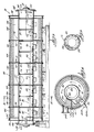
- the distillation device 10 of the invention includes a generally cylindrical, stationary, outer housing 12 supported horizontally on a plurality of axially spaced legs 14 and a generally cylindrical distillation chamber or drum 16 extending through the outer housing 12 and mounted for coaxial rotation about a generally horizontal axis 18.
- the outer housing 12 serves as an insulated heating jacket for the distillation drum 16 in which an ammoniacal leaching solution containing extracted copper is heated to drive off ammonia, carbon dioxide and water and to precipitate CuO (cupric oxide) as described in more detail below.
- the outer housing 12 has a generally cylindrical outer shell assembly 20 comprised of a plurality of flanged, semi-cylindrical top and bottom segments 22 and 24 suitably fastened together by bolts (not shown) or the like.
- the shell assembly 20 also has end plates 26 and 28 including a central aperture through which the distillation drum 16 extends.
- the interior of the shell segments 22 and 24 are lined with two or more layers of an insulative, refractory material 30, 32 and the end plates 26 and 28 are lined with an insulative, refractory material 33.
- the interior of the housing 12 is divided into a plurality of heating chambers 34, 36, 38, 40 and 42 by vertically extending strips 44 of barrier material, such as a 2.54 cm (1-inch) ceramic blanket.
- barrier material such as a 2.54 cm (1-inch) ceramic blanket.
- the exterior of the distillation drum 16 is heated by a plurality of gas-fired burners 46 mounted in the bottom portion of the shell assembly 20.
- the heating chambers 34, 36, 38, 40 and 42 are arranged so that each burner 46 heats a reasonably well defined zone of the distillation drum 16 and all the heating chambers includes two burners 46, except the first chamber 34.
- the burner flame is directed upwardly at an angle toward the outer surface of the distillation drum 16 and the exhaust gases circulate through the respective heating chamber in the direction of arrows 48.
- the exhaust gases are exhausted through a rectangular exhaust port 50 for each burner and into a stack 52.
- a horizontally extending strip 54 of barrier material which can be the same material as the vertical barriers 44, separates the top and bottom portions of each heating chamber and a radially extending rib 56 of insulative, refractory material closely spaced from the outer surface of the distillation drum 16 deters recirculation of the exhaust gases.
- the rate of heating along the length of the distillation drum 16 can be varied if desired by simply adjusting the flow of gas and air to the individual burners 46. Fins can be provided on the outer surface of the distillation drum 16 to enhance heat transfer.
- the inlet and outlet ends 58 and 60 of the distillation drum 16 are closed by respective end plates 62 and 64 and include radially extending flanges 66 and 68 which are rotatably supported on a pair of roller bearing assemblies 70.
- the distillation drum 16 is rotated, in the counter-clockwise direction as viewed in Figs. 2 and 4, by a motor 72 which drives a chain 74 trained over a sprocket 76 mounted on the outlet end 60 of the distillation drum 16.
- the distillation drum 16 includes a plurality of annular baffles 80 which are axially spaced at uniform intervals and extend radially inwardly from the interior wall 82 of the distillation drum 16 to define a plurality (e.g., 10) of compartments 84,86,88,90,92, 94,96,98,100 and 102.
- the spacing between adjacent baffles 80 preferably generally corresponds with the heating zone for a burner 46.
- each baffle 80 is removably mounted by bolts or the like on a retention ring 106 fixably mounted on the interior wall 80 of the distillation drum 16. This permits baffles of different radial heights to be used when desired as explained in more detail below.
- An ammoniacal leaching solution 108 containing copper is continuously introduced under pressure into the first compartment 84 of the distillation drum 16 via a pump 110 and a conduit 112. As a guide, this pressure can be about 69 to about 103.5 kN/m2 (about 10 to about 15 psig).
- the conduit 112 has an outlet 114 which extends through the inlet plate 62 and a rotary seal assembly 116 mounted on the inlet end plate 62.
- the solution 108 is maintained under pressure to insure precipitation of CuO (cupric oxide), rather than cupric carbonate, from the solution.
- the burners 46 heat the solution to a temperature above its boiling point at that pressure as it flows over the baffles 80 toward the outlet end 60 of the rotating distillation drum 16. As a guide, this temperature usually is in the range of about 93 to about 121°C (about 200 to about 250°F). CuO (cupric oxide) precipitates from the solution 108 as it is concentrated upon the evaporation of ammonia, carbon dioxide and water.
- a concentrated slurry 118 containing the CuO (cupric oxide) precipitate is continuously withdrawn from the last or recovery compartment 102 of the distillation drum 16 via a pump 120 and a conduit 122.
- the conduit 122 has an inlet 124 which extends through the outlet end plate 64 and a rotary seal assembly 126 mounted on the outlet end plate 64.
- the evaporated gases (NH3, CO2 and water vapor) formed in the distillation drum 16 are withdrawn from the inlet end 58 of the distillation drum 16 via a conduit 128 extending through the rotary seal assembly 116. These gases can be condensed in a condensor 130 and recycled for reuse in the leaching process. Thus, the flow of the evaporating gases is countercurrent to the solution flow.
- a low volume flow of air can be introduced into the outlet end 60 of the distillation drum 16 through two small lines 132 and 134 extending through the rotary seal 126.
- the slurry 118 from the distillation drum 16 is routed to a suitable device 136 for separating solids from a liquid, such as a filter or a centrifuge, to recover the cupric oxide.
- a suitable device 136 for separating solids from a liquid, such as a filter or a centrifuge, to recover the cupric oxide.
- a tumbling medium 140 Disposed in each of the compartments 84, 86, 88, 90, 92, 94, 96, 98 and 100 is a tumbling medium 140 comprised of a plurality of individual elements which rub against each other, the interior wall 82 of the distillation drum 16, and the sides of the baffles 80 to provide, during rotation of the distillation drum 16, a grinding or scrubbing action which prevents a scale build up of the precipitating CuO (cupric oxide).
- the tumbling medium 140 also provides areas for nucleation of the CuO (cupric oxide) precipitate and the turbulence created in the solution 108 by its tumbling action increases the rate of heat transfer from the distillation drum wall 82 to the solution.
- the last or recovery compartment 102 preferably does not contain tumbling medium.
- the tumbling medium is made from a material, such as steel or ceramic, which is inert with respect to the solution and the scale forming precipitate and preferably is somewhat softer than the material of the distillation drum 16 and the baffle 80 in order to minimize wear.
- the tumbling medium 140 can have a variety of outer surface configurations so long as the desired scrubbing action is produced. Recessed or concave surfaces which might be "hidden” from rubbing with other elements and, therefore, sites for potential scale build up, should be avoided. Accordingly, a substantial portion of the outer surface of the tumbling medium 140 should be convex in order to promote random rolling or tumbling during rotation of the distillation drum 16.
- the tumbling medium 140 preferably is in the form of the spherical balls.
- the balls should be relatively small with respect to the space between the baffles 80 in order to insure a good scrubbing action and a mixture of balls of different sizes is preferred for that reason.
- the balls can have diameters ranging from about 3 mm up to about 38 mm (about 1/8 inch up to 1 1/2 inches).
- the distillation drum 16 is rotated at a non-centrifuging speed with respect to the solution and the tumbling medium, that is, at a speed below which the tumbling medium 140 and/or the solution 108 is held against the interior wall 82 of the distillation drum 16.
- a non-centrifuging speed with respect to the solution and the tumbling medium, that is, at a speed below which the tumbling medium 140 and/or the solution 108 is held against the interior wall 82 of the distillation drum 16.
- the speed of rotation usually will be in the order of 10-20 revolutions per minute.
- the tumbling medium 140 can serve to grind the scale-forming precipitate to a predetermined size by varying the amount, composition, size and hardness of the tumbling medium and the rotational speed of the distillation drum.
- the baffles 80 can serve to prevent back mixing of the solution as it flows through the distillation drum 16.
- the tumbling medium 140 in each of the compartments, 84, 86, 88, 90, 92, 94, 96, 98, and 100 is below the radial heights of the respective baffles 80 and the radial heights of the baffles 80 in at least the last half of the distillation drum progressively decrease in a direction toward the outlet end 60.
- This arrangement minimizes back mixing, but does permit some scale build up on the edges of the baffles 80, the extent of which depends on the level of the tumbling medium 140 relative to the radial height of the baffles 80.
- the baffles 80 in the first half of the distillation drum 16 have a uniform radial height which is less than that of the baffle separating compartments 94 and 96.
- the radial heights of the baffles 80 in the last half of the distillation drum 16, where back mixing is a greater concern progressively decrease and the solution overflows the baffles from one compartment to the next. If desired, the radial heights of the baffles 80 can progressively decrease along the entire length of the distillation drum 16 so that the solution overflows the baffles from each compartment to the next.
- the level of the tumbling medium 140 in each compartment preferably is below the radial heights of the respective baffles as illustrated. It can be above the radial heights of the baffles 80 to prevent scale build up on the edges of the baffles. However, this permits some back mixing which may outweigh the advantage of eliminating scale build up in some cases.
- the level of the tumbling medium 140 and the depth of the solution 108 along the length of the distillation drum 16 can be controlled by inclining the rotational axis downwardly in a direction from the inlet end toward the outlet end at a small angle in the order of about 5° from the horizontal.
- the radial heights of the baffles 80 can be varied to adjust the retention time of the solution in the distillation drum. This adjustment can be accomplished by simply removing one set of the removably mounted baffles and replacing it with another set of baffles having the desired radial heights.
- Heat sources other than gas burners can be used, for example, electrical resistance heaters or a steam jacket.
- the device With suitable enclosures and rotary seal assemblies on the inlet and outlet ends of the distillation drum 16, the device can be operated under vacuum conditions as well as under pressure as described above.
- the distillation device and method provided by the invention have several advantages.
- a wide variety of scale-forming materials can be efficiently precipitated or crystallized from solution with little or no scale formation because of the nucleation sites and scouring action provided by the tumbling medium.
- the turbulent action of the tumbling medium increases the degree of the precipitation per unit of heat.
- External liquids, such as steam, which can upset the water balance are not required as is the case with some prior systems.
- the precipitate can be conveniently ground to a predetermined particle size by adjusting the amount, composition, size and hardness of the tumbling medium and the rotational speed of the distillation drum.
Landscapes
- Chemical & Material Sciences (AREA)
- Organic Chemistry (AREA)
- Chemical Kinetics & Catalysis (AREA)
- Inorganic Chemistry (AREA)
- Vaporization, Distillation, Condensation, Sublimation, And Cold Traps (AREA)
- Manufacture And Refinement Of Metals (AREA)
- Physical Or Chemical Processes And Apparatus (AREA)
- Fertilizers (AREA)
- Compounds Of Alkaline-Earth Elements, Aluminum Or Rare-Earth Metals (AREA)
Abstract
Description
- This invention relates to a device and method for precipitating dissolved scale-forming materials from solution.
- In recovery of certain metals, such as the recovery of copper and nickel from ores, metal oxides or carbonates are separated from gangue by an ammonia-carbon dioxide leaching process. A similar process is used as one of the steps in recovering metals from scrap materials, such as copper from printed circuit boards.
- Such metal oxides or carbonates are commonly separated from the ammoniacal leaching solution by distillation. Severe maintenance and operational difficulties arise because the metal oxides and/or carbonates precipitating from the solution usually are scale-forming and tend to deposit and form a scale build-up on the interior surfaces of the distillation equipment. Consequently, packing columns, sieve plate columns, bubble cup plate columns and similar equipment used in other continuous distillation processes generally are not suitable because the scale-forming precipitate eventually causes plugging, requiring a shutdown to remove the scale.
- Various attempts have been made to minimize this scale build-up problem, such as adding mechanical scrapers, providing some sort of agitation, coating the exposed surfaces with a synthetic plastic material, and using a series of kettles which are agitated by a countercurrent flow of steam. While these approaches have had some degree of success, most still permit some scale-buildup which eventually must be removed.
- A paper entitled "Stripping With Simultaneous Solids Generation Using Turbulent Bed Contactor" and presented at the CIM Conference of Metallurgists at Montreal, Canada on August 28, 1978, discloses another approach in which a so-called turbulent bed contactor is used for stripping ammonia from an ammoniacal solution containing nickel carbonate. Each tray in the tower includes a bed of plastic spheres constrained between vertically spaced supporting grids. Gases passing through the beds countercurrently to the liquid flow causes turbulent movement of the spheres which minimizes the deposit of solids on the spheres, the grids and the interior walls of the tower. However, an external source of steam is required to produce the necessary turbulence of the balls.
- Rotary drums including a tumbling medium have been used for the distilling various liquids and as liquid reactors. Examples of such prior uses are disclosed in U.S. Patents 1,814,249, 2,098,054, 2,174,008, 2,511,742 and 2,735,807. None of these patents discloses a distillation device arranged and operated in accordance with applicants' invention to precipitate a scale-forming material from solution with minimum scale buildup, while increasing the degree of the precipitation per unit of heat and obviating the need for external steam or the like.
- According to a first aspect of the present invention there is provided a method for precipitating dissolved scale-forming materials from solution comprising the steps of providing an elongated, cylindrical distillation chamber mounted for rotation about a generally horizontal axis and including a plurality of axially spaced annular baffles extending radially inwardly from the interior wall of said chamber to define a plurality of compartments; providing a tumbling medium in the compartments comprising individual elements which are inert with respect to the solution and the scale-forming material and which rub against each other, the interior walls of the chamber and the sides of the baffles in response to rotation of the chamber; rotating the chamber at non-centrifuging speed with respect to the solution and the tumbling medium; continuously introducing the solution into an inlet end of the chamber in a sufficient quantity to flow over the baffles toward the opposite, outlet end of said chamber; heating the solution in the chamber above its boiling point to evaporate volatile materials and precipitate the scale-forming material from the solution as its flows through the chamber; continuously withdrawing gases evaporating from the solution from the inlet end of the chamber; and continuously withdrawing a slurry containing the precipitated scale-forming material from the outlet end of the chamber.
- The invention also provides a device for precipitating dissolved, scale-forming materials from a solution including an elongated, cylindrical distillation drum or chamber mounted for rotation about a generally horizontal axis and a plurality of axially spaced baffles extending radially inwardly from the interior wall of the distillation chamber, a tumbling medium disposed in the compartments comprising individual elements which are inert with respect to the solution and scale-forming precipitate being treated and which, in response to rotation of the distillation chamber, rub against each other, the interior walls of the chamber and the sides of the baffles, means for externally heating the chamber, and means for rotating the distillation chamber.
- While the distillation chamber is being rotated at a non-centrifuging speed with respect to the solution and tumbling medium, the solution is continuously introduced into an inlet end of the chamber and is heated to a temperature above its boiling point to evaporate volatile materials and precipitate the scale-forming material from the solution as it flows over the baffles toward the outlet end of the distillation chamber. The tumbling medium provides a grinding or scrubbing action which minimizes scale build-up of the scale-forming precipitate. A slurry containing the scale-forming precipitate is continuously withdrawn from the outlet end of the distillation chamber and the evaporated gases are continuously withdrawn from the inlet end of the distillation chamber.
- Preferably, the radial heights of at least a some of the baffles progressively decrease in a direction from the inlet toward the outlet and the level of the tumbling medium in the compartments is below the radial heights of the respective baffles so that solution overflows the baffles from one compartment to the next, thereby eliminating back mixing.
- The method and device in accordance with the invention enable precipitation of scale-forming materials from solution with a minimum build-up of scale, and operation thereof can be conveniently adjusted for use in precipitating or crystallizing a wide variety of scale-forming materials.
- Examples of the method and device in accordance with the invention will now be described with reference to the accompanying drawings, in which:-
- Fig. 1 is a partial side elevation view of a distillation device of the invention and a diagrammatic representation of auxilliary equipment for practicing the method of the invention.
- Fig. 2 is an end elevation view of the distillation device taken generally along line 2-2 in Fig. 1.
- Fig. 3 is a sectional elevational view of the distillation device of Fig. 1 shown with the distillation chamber containing an ammonical leaching solution.
- Fig. 4 is a sectional view taken generally along line 4-4 in Fig. 3.
- Fig. 5 is a sectional view taken generally along line 5-5 in Fig. 3.
- The distillation device and method provided by the invention is particularly suitable for the recovery of metal oxides and carbonates from ammoniacal leaching solutions in which scaling and fouling can cause severe maintenance and operational difficulties. Accordingly, it will be described in connection with recovering cupric oxide from an ammonical leaching solution. However, the device and method can be used in many other precipitation or crystallization systems where the prevention of scale build up is desirable.
- Referring to the drawings, the
distillation device 10 of the invention includes a generally cylindrical, stationary,outer housing 12 supported horizontally on a plurality of axiallyspaced legs 14 and a generally cylindrical distillation chamber ordrum 16 extending through theouter housing 12 and mounted for coaxial rotation about a generallyhorizontal axis 18. Theouter housing 12 serves as an insulated heating jacket for thedistillation drum 16 in which an ammoniacal leaching solution containing extracted copper is heated to drive off ammonia, carbon dioxide and water and to precipitate CuO (cupric oxide) as described in more detail below. - The
outer housing 12 has a generally cylindricalouter shell assembly 20 comprised of a plurality of flanged, semi-cylindrical top andbottom segments shell assembly 20 also hasend plates 26 and 28 including a central aperture through which thedistillation drum 16 extends. The interior of theshell segments refractory material end plates 26 and 28 are lined with an insulative,refractory material 33. - The interior of the
housing 12 is divided into a plurality ofheating chambers strips 44 of barrier material, such as a 2.54 cm (1-inch) ceramic blanket. The exterior of thedistillation drum 16 is heated by a plurality of gas-firedburners 46 mounted in the bottom portion of theshell assembly 20. Theheating chambers burner 46 heats a reasonably well defined zone of thedistillation drum 16 and all the heating chambers includes twoburners 46, except the first chamber 34. - Referring to Fig. 4, the burner flame is directed upwardly at an angle toward the outer surface of the
distillation drum 16 and the exhaust gases circulate through the respective heating chamber in the direction of arrows 48. The exhaust gases are exhausted through a rectangular exhaust port 50 for each burner and into astack 52. A horizontally extendingstrip 54 of barrier material, which can be the same material as thevertical barriers 44, separates the top and bottom portions of each heating chamber and a radially extendingrib 56 of insulative, refractory material closely spaced from the outer surface of thedistillation drum 16 deters recirculation of the exhaust gases. - With this arrangement, the rate of heating along the length of the
distillation drum 16 can be varied if desired by simply adjusting the flow of gas and air to theindividual burners 46. Fins can be provided on the outer surface of thedistillation drum 16 to enhance heat transfer. - The inlet and
outlet ends 58 and 60 of thedistillation drum 16 are closed byrespective end plates 62 and 64 and include radially extendingflanges assemblies 70. Thedistillation drum 16 is rotated, in the counter-clockwise direction as viewed in Figs. 2 and 4, by a motor 72 which drives achain 74 trained over asprocket 76 mounted on the outlet end 60 of thedistillation drum 16. - The
distillation drum 16 includes a plurality ofannular baffles 80 which are axially spaced at uniform intervals and extend radially inwardly from theinterior wall 82 of thedistillation drum 16 to define a plurality (e.g., 10) ofcompartments adjacent baffles 80 preferably generally corresponds with the heating zone for aburner 46. As best shown in Fig. 5, eachbaffle 80 is removably mounted by bolts or the like on aretention ring 106 fixably mounted on theinterior wall 80 of thedistillation drum 16. This permits baffles of different radial heights to be used when desired as explained in more detail below. - An
ammoniacal leaching solution 108 containing copper is continuously introduced under pressure into thefirst compartment 84 of thedistillation drum 16 via a pump 110 and aconduit 112. As a guide, this pressure can be about 69 to about 103.5 kN/m² (about 10 to about 15 psig). Theconduit 112 has anoutlet 114 which extends through theinlet plate 62 and arotary seal assembly 116 mounted on theinlet end plate 62. Thesolution 108 is maintained under pressure to insure precipitation of CuO (cupric oxide), rather than cupric carbonate, from the solution. - The
burners 46 heat the solution to a temperature above its boiling point at that pressure as it flows over thebaffles 80 toward the outlet end 60 of the rotatingdistillation drum 16. As a guide, this temperature usually is in the range of about 93 to about 121°C (about 200 to about 250°F). CuO (cupric oxide) precipitates from thesolution 108 as it is concentrated upon the evaporation of ammonia, carbon dioxide and water. - A concentrated slurry 118 containing the CuO (cupric oxide) precipitate is continuously withdrawn from the last or recovery compartment 102 of the
distillation drum 16 via apump 120 and aconduit 122. Theconduit 122 has aninlet 124 which extends through the outlet end plate 64 and arotary seal assembly 126 mounted on the outlet end plate 64. - The evaporated gases (NH₃, CO₂ and water vapor) formed in the
distillation drum 16 are withdrawn from theinlet end 58 of thedistillation drum 16 via a conduit 128 extending through therotary seal assembly 116. These gases can be condensed in acondensor 130 and recycled for reuse in the leaching process. Thus, the flow of the evaporating gases is countercurrent to the solution flow. A low volume flow of air can be introduced into the outlet end 60 of thedistillation drum 16 through two small lines 132 and 134 extending through therotary seal 126. - The slurry 118 from the
distillation drum 16 is routed to asuitable device 136 for separating solids from a liquid, such as a filter or a centrifuge, to recover the cupric oxide. - Disposed in each of the
compartments tumbling medium 140 comprised of a plurality of individual elements which rub against each other, theinterior wall 82 of thedistillation drum 16, and the sides of thebaffles 80 to provide, during rotation of thedistillation drum 16, a grinding or scrubbing action which prevents a scale build up of the precipitating CuO (cupric oxide). The tumblingmedium 140 also provides areas for nucleation of the CuO (cupric oxide) precipitate and the turbulence created in thesolution 108 by its tumbling action increases the rate of heat transfer from thedistillation drum wall 82 to the solution. The last or recovery compartment 102 preferably does not contain tumbling medium. - The tumbling medium is made from a material, such as steel or ceramic, which is inert with respect to the solution and the scale forming precipitate and preferably is somewhat softer than the material of the
distillation drum 16 and thebaffle 80 in order to minimize wear. - The tumbling medium 140 can have a variety of outer surface configurations so long as the desired scrubbing action is produced. Recessed or concave surfaces which might be "hidden" from rubbing with other elements and, therefore, sites for potential scale build up, should be avoided. Accordingly, a substantial portion of the outer surface of the tumbling medium 140 should be convex in order to promote random rolling or tumbling during rotation of the
distillation drum 16. The tumbling medium 140 preferably is in the form of the spherical balls. The balls should be relatively small with respect to the space between thebaffles 80 in order to insure a good scrubbing action and a mixture of balls of different sizes is preferred for that reason. As a guide, the balls can have diameters ranging from about 3 mm up to about 38 mm (about 1/8 inch up to 1 1/2 inches). - In order to provide the desired scrubbing or grinding action, the
distillation drum 16 is rotated at a non-centrifuging speed with respect to the solution and the tumbling medium, that is, at a speed below which the tumblingmedium 140 and/or thesolution 108 is held against theinterior wall 82 of thedistillation drum 16. As a guide, for a distillation drum 9.144 m (30 feet) long and having an inside diameter approximately 1.22 m (4 feet), the speed of rotation usually will be in the order of 10-20 revolutions per minute. The tumbling medium 140 can serve to grind the scale-forming precipitate to a predetermined size by varying the amount, composition, size and hardness of the tumbling medium and the rotational speed of the distillation drum. - The
baffles 80 can serve to prevent back mixing of the solution as it flows through thedistillation drum 16. In the preferred embodiment illustrated, the tumbling medium 140 in each of the compartments, 84, 86, 88, 90, 92, 94, 96, 98, and 100 is below the radial heights of therespective baffles 80 and the radial heights of thebaffles 80 in at least the last half of the distillation drum progressively decrease in a direction toward the outlet end 60. This arrangement minimizes back mixing, but does permit some scale build up on the edges of thebaffles 80, the extent of which depends on the level of the tumbling medium 140 relative to the radial height of thebaffles 80. - The majority of precipitation usually occurs in the first half of the
distillation drum 16 and substantially only evaporation of the volatile material takes place in the last half. Thus, in the specific construction illustrated, thebaffles 80 in the first half of thedistillation drum 16, where back mixing is a lesser concern, have a uniform radial height which is less than that of thebaffle separating compartments baffles 80 in the last half of thedistillation drum 16, where back mixing is a greater concern, progressively decrease and the solution overflows the baffles from one compartment to the next. If desired, the radial heights of thebaffles 80 can progressively decrease along the entire length of thedistillation drum 16 so that the solution overflows the baffles from each compartment to the next. - The level of the tumbling medium 140 in each compartment preferably is below the radial heights of the respective baffles as illustrated. It can be above the radial heights of the
baffles 80 to prevent scale build up on the edges of the baffles. However, this permits some back mixing which may outweigh the advantage of eliminating scale build up in some cases. The level of the tumblingmedium 140 and the depth of thesolution 108 along the length of thedistillation drum 16 can be controlled by inclining the rotational axis downwardly in a direction from the inlet end toward the outlet end at a small angle in the order of about 5° from the horizontal. The radial heights of thebaffles 80 can be varied to adjust the retention time of the solution in the distillation drum. This adjustment can be accomplished by simply removing one set of the removably mounted baffles and replacing it with another set of baffles having the desired radial heights. - Heat sources other than gas burners can be used, for example, electrical resistance heaters or a steam jacket. With suitable enclosures and rotary seal assemblies on the inlet and outlet ends of the
distillation drum 16, the device can be operated under vacuum conditions as well as under pressure as described above. - From the foregoing description it can be seen that the distillation device and method provided by the invention have several advantages. A wide variety of scale-forming materials can be efficiently precipitated or crystallized from solution with little or no scale formation because of the nucleation sites and scouring action provided by the tumbling medium. The turbulent action of the tumbling medium increases the degree of the precipitation per unit of heat. External liquids, such as steam, which can upset the water balance are not required as is the case with some prior systems. The precipitate can be conveniently ground to a predetermined particle size by adjusting the amount, composition, size and hardness of the tumbling medium and the rotational speed of the distillation drum.
- Without further elaboration, it is believed that one skilled in the art can, using the preceding description, utilize the present invention to its fullest extent. The following example is presented to exemplify a preferred embodiment of the invention and should not be construed as a limitation thereof.
- The following operating parameters are typical for recovering CuO (cupric oxide) from an ammoniacal leaching solution used to extract copper from a scrap materail, such as printed circuit boards.
Distiller Drum Dimensions Length, 9.144 m (30 feet) Inside diameter, 1.22 m ( 4 feet) Distiller Drum Operation Temperature, 93.3°-121°C (200-250°F) Pressure, 68.95-103.5 kN/m² (10-15 psig) Rotational speed, rpm 14 Tumbling medium mixed steel and ceramic balls, 3.175mm and 38.1mm (1/8 in. and 1 1/2 inch) diameter Solution In (Conduit 112) Feed rate, gpm 10.25 Composition, wt. % NH₃ 6.0 CO₂ 4.0 Cu⁺⁺ 5.5 Water 84.5 Slurry Out (Conduit 122) Withdrawal rate, gpm. 5 Composition, wt. % NH₃ 0.5 CO₂ 0.3 Cu⁺⁺ 0.5 CuO 5.0 Water 93.7 Vapors Out (Conduit 128) Flow rate, 1160.8 kg/hr (2559 lbs/hr) Pressure, 68.95 kN/m² (10 psig) max Composition, mole % NH₃ 11.4 CO₂ 7.6 Water 81.0
Claims (16)
- A method for precipitating dissolved scale-forming material from a solution including the steps of:(a) providing an elongated, cylindrical distillation chamber mounted for rotation about a generally horizontal axis and including a plurality of axially spaced annular baffles extending radially inwardly from the interior wall of said chamber at a height less than the inside radius of said chamber to define a plurality of compartments;(b) providing a tumbling medium in the compartments comprising individual elements which are inert with respect to the solution and the scale-forming material and which rub against each other, the interior walls of the chamber and the sides of the baffles in response to rotation of the chamber;(c) rotating the chamber at non-centrifuging speed with respect to the solution and the tumbling medium;(d) continuously introducing the solution into an inlet end of the chamber in a sufficient quantity to flow over the baffles toward the opposite, outlet end of said chamber;(e) heating the solution in the chamber above its boiling point to evaporate volatile materials and precipitate scale-forming material from the solution as it flows through the chamber;(f) continuously withdrawing a slurry containing the precipitated scale-forming material from the outlet end of the chamber; and(g) continuously withdrawing gases evaporating from the solution from the inlet end of the chamber to thereby provide countercurrent flow of the evaporated gases and the solution.
- A method according to claim 1 wherein the level of the tumbling medium in the compartments is below the radial heights of the respective baffles and the radial heights of at least some of the baffles progressively decrease in a direction from the inlet end toward the outlet end of the chamber so that the solution overflows said baffles from one compartment to the next.
- A method according to claim 1 or claim 2 wherein the tumbling medium is in the form of spherical balls.
- A method according to any one of claims 1 to 3 wherein the solution is an aqueous, ammoniacal leaching solution containing copper, ammonia and carbon dioxide, the chamber is heated to a temperature of about 93 to 121°C (about 200 to about 250°F) and is maintained at a pressure of about 69 to about 103.5 kN/m² (about 10 to about 15 psig), the gases withdrawn from the inlet end of the chamber contain ammonia, carbon dioxide and water vapor, and the slurry withdrawn from the outlet end of the chamber contains CuO (cupric oxide).
- A method according to claim 4 including the further step of:(h) separating CuO (cupric oxide) from the slurry withdrawn from the outlet end of the chamber.
- A method according to claim 1 wherein the level of the tumbling medium in the compartments is above the radial heights of at least some of the respective baffles.
- A method according to claim 1 wherein the rotational axis of the chamber is at a slight downward incline in the direction from the inlet end toward the outlet end of the chamber.
- A method according to claim 7 wherein the radial heights of the baffles are substantially uniform.
- A method according to any one of the preceding claims wherein the tumbling medium is made from a material which is softer than that of the chamber interior wall and the baffles so as to minimize wear.
- A device for precipitating dissolved, scale-forming materials from a solution including
an elongated, cylindrical, distillation chamber mounted for rotation about a generally horizontal axis and including a plurality of axially spaced annular baffles extending radially inwardly from the interior wall of said chamber at a height less than the inside radius of said chamber to define a plurality of compartments;
a tumbling medium disposed in said compartments comprising individual elements which are inert with respect to the solution and the scale-forming material and which, in response to rotation of said chamber, rub against each other, the interior walls of said chamber and the sides of said baffles to prevent the buildup of scale thereon;
means for rotating said chamber,
means for continuously introducing the solution into an inlet end of said chamber for flow toward the opposite, outlet end of said chamber;
means for externally heating said chamber to raise the temperature of the solution contained therein above its boiling point;
means for continuously withdrawing a slurry containing the precipitated scale-forming materials from the outlet end of said chamber; and
means for continuously withdrawing vapors evaporating from the solution from the inlet end of said chamber to thereby provide countercurrent flow of the evaporated vapors and the solution. - A device according to claim 10 wherein the level of said tumbling medium in said compartments is below the radial heights of the respective baffles.
- A device according to claim 10 wherein the level of said tumbling medium in said chamber is above the radial heights of at least some of said baffles.
- A device according to claim 10 wherein the radial heights of at least some of said baffles progressively decrease in the direction from the inlet end toward the outlet end of said chamber.
- A device according to claim 10 wherein the rotational axis of said chamber is at a slight downward incline in the direction from the inlet end toward the outlet end of said chamber; and the radial heights of said baffles are substantially uniform.
- A device according to any one of claims 10 to 14 wherein said tumbling medium elements are made from a material which is softer than that of said chamber and said baffles so as to minimize wear.
- A device according to any one of claims 10 to 15 wherein said tumbling medium is in the form of spherical balls.
Priority Applications (6)
| Application Number | Priority Date | Filing Date | Title |
|---|---|---|---|
| US06/445,224 US4686003A (en) | 1982-12-10 | 1982-12-10 | Precipitation of scale-forming materials from solution |
| AT87305956T ATE81155T1 (en) | 1987-07-06 | 1987-07-06 | METHOD AND DEVICE FOR THE FALLATION OF CRUST-FORMING MATERIALS FROM SOLUTIONS. |
| EP87305956A EP0298162B1 (en) | 1987-07-06 | 1987-07-06 | Method and apparatus for precipitation of scale-forming materials from solution |
| DE8787305956T DE3782055T2 (en) | 1987-07-06 | 1987-07-06 | METHOD AND DEVICE FOR FALLING SCAFFOLDING SUBSTANCES FROM SOLUTIONS. |
| SG54893A SG54893G (en) | 1982-12-10 | 1993-04-29 | Method and apparatus for precipitation of scale-forming materials from solution |
| HK683/93A HK68393A (en) | 1987-07-06 | 1993-07-15 | Method and apparatus for precipitation of scale-forming materials from solution |
Applications Claiming Priority (1)
| Application Number | Priority Date | Filing Date | Title |
|---|---|---|---|
| EP87305956A EP0298162B1 (en) | 1987-07-06 | 1987-07-06 | Method and apparatus for precipitation of scale-forming materials from solution |
Publications (2)
| Publication Number | Publication Date |
|---|---|
| EP0298162A1 EP0298162A1 (en) | 1989-01-11 |
| EP0298162B1 true EP0298162B1 (en) | 1992-09-30 |
Family
ID=8197960
Family Applications (1)
| Application Number | Title | Priority Date | Filing Date |
|---|---|---|---|
| EP87305956A Expired - Lifetime EP0298162B1 (en) | 1982-12-10 | 1987-07-06 | Method and apparatus for precipitation of scale-forming materials from solution |
Country Status (4)
| Country | Link |
|---|---|
| EP (1) | EP0298162B1 (en) |
| AT (1) | ATE81155T1 (en) |
| DE (1) | DE3782055T2 (en) |
| HK (1) | HK68393A (en) |
Families Citing this family (1)
| Publication number | Priority date | Publication date | Assignee | Title |
|---|---|---|---|---|
| CN114392574B (en) * | 2021-12-24 | 2023-08-29 | 南昌工程学院 | A plant continuous distillation extraction device |
Citations (1)
| Publication number | Priority date | Publication date | Assignee | Title |
|---|---|---|---|---|
| US2022054A (en) * | 1928-12-03 | 1935-11-26 | Harry S Reed | Apparatus and process for distilling or cracking hydrocarbons or the like |
Family Cites Families (5)
| Publication number | Priority date | Publication date | Assignee | Title |
|---|---|---|---|---|
| US2735807A (en) * | 1956-02-21 | Self-cleaning apparatus for purifying | ||
| US1814249A (en) * | 1929-08-21 | 1931-07-14 | William T Hancock | Cracking still |
| US2098054A (en) * | 1935-11-23 | 1937-11-02 | Du Pont | Ball mill attack of titaniferous ores |
| US2174008A (en) * | 1938-01-29 | 1939-09-26 | Nat Aniline & Chem Co Inc | Distillation of amines from reduction masses |
| US2511742A (en) * | 1947-11-19 | 1950-06-13 | Lincoln M Shafer | Ball mill and vapor condenser |
-
1987
- 1987-07-06 AT AT87305956T patent/ATE81155T1/en not_active IP Right Cessation
- 1987-07-06 DE DE8787305956T patent/DE3782055T2/en not_active Expired - Fee Related
- 1987-07-06 EP EP87305956A patent/EP0298162B1/en not_active Expired - Lifetime
-
1993
- 1993-07-15 HK HK683/93A patent/HK68393A/en not_active IP Right Cessation
Patent Citations (1)
| Publication number | Priority date | Publication date | Assignee | Title |
|---|---|---|---|---|
| US2022054A (en) * | 1928-12-03 | 1935-11-26 | Harry S Reed | Apparatus and process for distilling or cracking hydrocarbons or the like |
Also Published As
| Publication number | Publication date |
|---|---|
| ATE81155T1 (en) | 1992-10-15 |
| DE3782055D1 (en) | 1992-11-05 |
| DE3782055T2 (en) | 1993-02-25 |
| EP0298162A1 (en) | 1989-01-11 |
| HK68393A (en) | 1993-07-23 |
Similar Documents
| Publication | Publication Date | Title |
|---|---|---|
| EP0693142B1 (en) | System for polymer crystallization | |
| US3582262A (en) | Multiple stage method for removing chlorine and entrained aluminum chloride particles from a waste gas stream | |
| JPH0680177B2 (en) | Liquid treatment method | |
| US4686003A (en) | Precipitation of scale-forming materials from solution | |
| US6017499A (en) | Apparatus for contacting solids in the form of freeflowing lumps with liquids or gases | |
| US3837491A (en) | Liquid purification apparatus and process | |
| US4329198A (en) | Apparatus for forced circulation evaporation | |
| US3976430A (en) | Forced circulation cooling crystallizer | |
| US3472304A (en) | Falling film evaporator | |
| US3888973A (en) | Method of increasing the speed of chemical reaction between liquid and solid reactants using centrifugal force | |
| US2917372A (en) | Liquid-gas contact reactor | |
| US3856477A (en) | Process for refining zirconium tetrachloride containing hafnium tetrachloride | |
| HK68393A (en) | Method and apparatus for precipitation of scale-forming materials from solution | |
| CA1310896C (en) | Precipitation of scale-forming materials from solution | |
| US3961903A (en) | Apparatus for reclaiming limestone mud | |
| US4157281A (en) | Method and apparatus for reclaiming solvents from solvent-bearing sludge material | |
| WO1994023802A1 (en) | Process and apparatus for destroying organic and carbonaceous waste | |
| KR950008624B1 (en) | Method and apparatus for precipitation of scaleable material from solution | |
| US3669623A (en) | Method for the regeneration of hydrochloric acid from spent pickle liquor and like solutions | |
| US3428426A (en) | Ammonia stripping process | |
| US4957627A (en) | Process for liquid-solid contact | |
| JP7584785B2 (en) | Apparatus and method for pyrolysis of organic waste | |
| US3660246A (en) | Distillation apparatus having concentric riser, expansion and condensing chambers | |
| US3841862A (en) | Cooling, condensation and purification of vapours and gases | |
| US4391228A (en) | Falling shot heating method and apparatus |
Legal Events
| Date | Code | Title | Description |
|---|---|---|---|
| PUAI | Public reference made under article 153(3) epc to a published international application that has entered the european phase |
Free format text: ORIGINAL CODE: 0009012 |
|
| AK | Designated contracting states |
Kind code of ref document: A1 Designated state(s): AT BE CH DE ES FR GB GR IT LI LU NL SE |
|
| 17P | Request for examination filed |
Effective date: 19890411 |
|
| 17Q | First examination report despatched |
Effective date: 19910111 |
|
| GRAA | (expected) grant |
Free format text: ORIGINAL CODE: 0009210 |
|
| AK | Designated contracting states |
Kind code of ref document: B1 Designated state(s): AT BE CH DE ES FR GB GR IT LI LU NL SE |
|
| PG25 | Lapsed in a contracting state [announced via postgrant information from national office to epo] |
Ref country code: IT Free format text: LAPSE BECAUSE OF FAILURE TO SUBMIT A TRANSLATION OF THE DESCRIPTION OR TO PAY THE FEE WITHIN THE PRE;WARNING: LAPSES OF ITALIAN PATENTS WITH EFFECTIVE DATE BEFORE 2007 MAY HAVE OCCURRED AT ANY TIME BEFORE 2007. THE CORRECT EFFECTIVE DATE MAY BE DIFFERENT FROM THE ONE RECORDED.SCRIBED TIME-LIMIT Effective date: 19920930 Ref country code: SE Effective date: 19920930 Ref country code: AT Effective date: 19920930 Ref country code: NL Effective date: 19920930 Ref country code: GR Free format text: LAPSE BECAUSE OF FAILURE TO SUBMIT A TRANSLATION OF THE DESCRIPTION OR TO PAY THE FEE WITHIN THE PRESCRIBED TIME-LIMIT Effective date: 19920930 Ref country code: FR Effective date: 19920930 |
|
| REF | Corresponds to: |
Ref document number: 81155 Country of ref document: AT Date of ref document: 19921015 Kind code of ref document: T |
|
| REF | Corresponds to: |
Ref document number: 3782055 Country of ref document: DE Date of ref document: 19921105 |
|
| PG25 | Lapsed in a contracting state [announced via postgrant information from national office to epo] |
Ref country code: ES Free format text: LAPSE BECAUSE OF FAILURE TO SUBMIT A TRANSLATION OF THE DESCRIPTION OR TO PAY THE FEE WITHIN THE PRESCRIBED TIME-LIMIT Effective date: 19930110 |
|
| EN | Fr: translation not filed | ||
| NLV1 | Nl: lapsed or annulled due to failure to fulfill the requirements of art. 29p and 29m of the patents act | ||
| PG25 | Lapsed in a contracting state [announced via postgrant information from national office to epo] |
Ref country code: LU Free format text: LAPSE BECAUSE OF NON-PAYMENT OF DUE FEES Effective date: 19930731 |
|
| PLBE | No opposition filed within time limit |
Free format text: ORIGINAL CODE: 0009261 |
|
| STAA | Information on the status of an ep patent application or granted ep patent |
Free format text: STATUS: NO OPPOSITION FILED WITHIN TIME LIMIT |
|
| 26N | No opposition filed | ||
| REG | Reference to a national code |
Ref country code: GB Ref legal event code: IF02 |
|
| PGFP | Annual fee paid to national office [announced via postgrant information from national office to epo] |
Ref country code: GB Payment date: 20050629 Year of fee payment: 19 |
|
| PGFP | Annual fee paid to national office [announced via postgrant information from national office to epo] |
Ref country code: CH Payment date: 20050721 Year of fee payment: 19 |
|
| PGFP | Annual fee paid to national office [announced via postgrant information from national office to epo] |
Ref country code: BE Payment date: 20050819 Year of fee payment: 19 |
|
| PGFP | Annual fee paid to national office [announced via postgrant information from national office to epo] |
Ref country code: DE Payment date: 20050831 Year of fee payment: 19 |
|
| PG25 | Lapsed in a contracting state [announced via postgrant information from national office to epo] |
Ref country code: GB Free format text: LAPSE BECAUSE OF NON-PAYMENT OF DUE FEES Effective date: 20060706 |
|
| PG25 | Lapsed in a contracting state [announced via postgrant information from national office to epo] |
Ref country code: LI Free format text: LAPSE BECAUSE OF NON-PAYMENT OF DUE FEES Effective date: 20060731 Ref country code: BE Free format text: LAPSE BECAUSE OF NON-PAYMENT OF DUE FEES Effective date: 20060731 Ref country code: CH Free format text: LAPSE BECAUSE OF NON-PAYMENT OF DUE FEES Effective date: 20060731 |
|
| PG25 | Lapsed in a contracting state [announced via postgrant information from national office to epo] |
Ref country code: DE Free format text: LAPSE BECAUSE OF NON-PAYMENT OF DUE FEES Effective date: 20070201 |
|
| REG | Reference to a national code |
Ref country code: CH Ref legal event code: PL |
|
| GBPC | Gb: european patent ceased through non-payment of renewal fee |
Effective date: 20060706 |
|
| BERE | Be: lapsed |
Owner name: *BOARD OF CONTROL OF MICHIGAN TECHNOLOGICAL UNIVER Effective date: 20060731 |