EP0295871B1 - Oil reclamation device - Google Patents
Oil reclamation device Download PDFInfo
- Publication number
- EP0295871B1 EP0295871B1 EP88305427A EP88305427A EP0295871B1 EP 0295871 B1 EP0295871 B1 EP 0295871B1 EP 88305427 A EP88305427 A EP 88305427A EP 88305427 A EP88305427 A EP 88305427A EP 0295871 B1 EP0295871 B1 EP 0295871B1
- Authority
- EP
- European Patent Office
- Prior art keywords
- fluid
- evaporator
- plate
- oil
- filter
- Prior art date
- Legal status (The legal status is an assumption and is not a legal conclusion. Google has not performed a legal analysis and makes no representation as to the accuracy of the status listed.)
- Expired - Lifetime
Links
- 239000012530 fluid Substances 0.000 claims description 55
- 238000001704 evaporation Methods 0.000 claims description 31
- 230000008020 evaporation Effects 0.000 claims description 31
- 238000010438 heat treatment Methods 0.000 claims description 18
- 230000008016 vaporization Effects 0.000 claims description 16
- 238000001914 filtration Methods 0.000 claims description 14
- 239000007788 liquid Substances 0.000 claims description 13
- 239000000463 material Substances 0.000 claims description 12
- 210000002445 nipple Anatomy 0.000 claims description 11
- 239000007787 solid Substances 0.000 claims description 10
- 238000009826 distribution Methods 0.000 claims description 8
- 239000012535 impurity Substances 0.000 claims description 7
- 229920000742 Cotton Polymers 0.000 claims description 6
- QVGXLLKOCUKJST-UHFFFAOYSA-N atomic oxygen Chemical compound [O] QVGXLLKOCUKJST-UHFFFAOYSA-N 0.000 claims description 6
- 239000002657 fibrous material Substances 0.000 claims description 6
- 229910052760 oxygen Inorganic materials 0.000 claims description 6
- 239000001301 oxygen Substances 0.000 claims description 6
- 238000009834 vaporization Methods 0.000 claims description 6
- 239000003112 inhibitor Substances 0.000 claims description 5
- 238000004891 communication Methods 0.000 claims description 4
- 239000000835 fiber Substances 0.000 claims description 4
- 239000004033 plastic Substances 0.000 claims description 3
- 150000004982 aromatic amines Chemical class 0.000 claims description 2
- 150000002989 phenols Chemical class 0.000 claims description 2
- 238000013022 venting Methods 0.000 claims description 2
- 239000003921 oil Substances 0.000 description 94
- 238000007789 sealing Methods 0.000 description 8
- 239000010409 thin film Substances 0.000 description 8
- VYPSYNLAJGMNEJ-UHFFFAOYSA-N Silicium dioxide Chemical compound O=[Si]=O VYPSYNLAJGMNEJ-UHFFFAOYSA-N 0.000 description 6
- 230000003647 oxidation Effects 0.000 description 6
- 238000007254 oxidation reaction Methods 0.000 description 6
- XLYOFNOQVPJJNP-UHFFFAOYSA-N water Substances O XLYOFNOQVPJJNP-UHFFFAOYSA-N 0.000 description 6
- 238000010276 construction Methods 0.000 description 5
- 239000000446 fuel Substances 0.000 description 5
- 239000010687 lubricating oil Substances 0.000 description 5
- -1 polypropylene Polymers 0.000 description 5
- OKTJSMMVPCPJKN-UHFFFAOYSA-N Carbon Chemical compound [C] OKTJSMMVPCPJKN-UHFFFAOYSA-N 0.000 description 3
- QAOWNCQODCNURD-UHFFFAOYSA-N Sulfuric acid Chemical compound OS(O)(=O)=O QAOWNCQODCNURD-UHFFFAOYSA-N 0.000 description 3
- 229910052799 carbon Inorganic materials 0.000 description 3
- 238000002485 combustion reaction Methods 0.000 description 3
- 239000002245 particle Substances 0.000 description 3
- 238000007670 refining Methods 0.000 description 3
- 239000000377 silicon dioxide Substances 0.000 description 3
- 235000011149 sulphuric acid Nutrition 0.000 description 3
- 229910000838 Al alloy Inorganic materials 0.000 description 2
- 239000004743 Polypropylene Substances 0.000 description 2
- 238000006243 chemical reaction Methods 0.000 description 2
- 229920001971 elastomer Polymers 0.000 description 2
- 239000010408 film Substances 0.000 description 2
- 230000007246 mechanism Effects 0.000 description 2
- 230000002093 peripheral effect Effects 0.000 description 2
- 229920001155 polypropylene Polymers 0.000 description 2
- 239000001117 sulphuric acid Substances 0.000 description 2
- 239000004215 Carbon black (E152) Substances 0.000 description 1
- 206010021580 Inadequate lubrication Diseases 0.000 description 1
- 229920000459 Nitrile rubber Polymers 0.000 description 1
- NINIDFKCEFEMDL-UHFFFAOYSA-N Sulfur Chemical compound [S] NINIDFKCEFEMDL-UHFFFAOYSA-N 0.000 description 1
- 239000002253 acid Substances 0.000 description 1
- 150000007513 acids Chemical class 0.000 description 1
- 239000003963 antioxidant agent Substances 0.000 description 1
- 230000003078 antioxidant effect Effects 0.000 description 1
- 235000006708 antioxidants Nutrition 0.000 description 1
- 230000004888 barrier function Effects 0.000 description 1
- 238000005452 bending Methods 0.000 description 1
- 230000008901 benefit Effects 0.000 description 1
- ZMRQTIAUOLVKOX-UHFFFAOYSA-L calcium;diphenoxide Chemical compound [Ca+2].[O-]C1=CC=CC=C1.[O-]C1=CC=CC=C1 ZMRQTIAUOLVKOX-UHFFFAOYSA-L 0.000 description 1
- 230000008859 change Effects 0.000 description 1
- 238000004140 cleaning Methods 0.000 description 1
- 150000001875 compounds Chemical class 0.000 description 1
- 238000009833 condensation Methods 0.000 description 1
- 230000005494 condensation Effects 0.000 description 1
- 239000000356 contaminant Substances 0.000 description 1
- 238000010924 continuous production Methods 0.000 description 1
- 230000001351 cycling effect Effects 0.000 description 1
- 239000002283 diesel fuel Substances 0.000 description 1
- 238000007599 discharging Methods 0.000 description 1
- 239000000428 dust Substances 0.000 description 1
- 210000005069 ears Anatomy 0.000 description 1
- 230000000694 effects Effects 0.000 description 1
- 239000007789 gas Substances 0.000 description 1
- 230000005484 gravity Effects 0.000 description 1
- 229930195733 hydrocarbon Natural products 0.000 description 1
- 150000002430 hydrocarbons Chemical class 0.000 description 1
- 230000006872 improvement Effects 0.000 description 1
- 238000009434 installation Methods 0.000 description 1
- 238000013332 literature search Methods 0.000 description 1
- 239000000314 lubricant Substances 0.000 description 1
- 238000005461 lubrication Methods 0.000 description 1
- 238000012423 maintenance Methods 0.000 description 1
- 230000013011 mating Effects 0.000 description 1
- 239000002923 metal particle Substances 0.000 description 1
- 239000000203 mixture Substances 0.000 description 1
- 239000010705 motor oil Substances 0.000 description 1
- 230000003472 neutralizing effect Effects 0.000 description 1
- 150000002978 peroxides Chemical class 0.000 description 1
- 238000000746 purification Methods 0.000 description 1
- 239000010802 sludge Substances 0.000 description 1
- 125000006850 spacer group Chemical group 0.000 description 1
- 239000010935 stainless steel Substances 0.000 description 1
- 229910001220 stainless steel Inorganic materials 0.000 description 1
- BDHFUVZGWQCTTF-UHFFFAOYSA-M sulfonate Chemical compound [O-]S(=O)=O BDHFUVZGWQCTTF-UHFFFAOYSA-M 0.000 description 1
- 229910052717 sulfur Inorganic materials 0.000 description 1
- 239000011593 sulfur Substances 0.000 description 1
- 230000008719 thickening Effects 0.000 description 1
- 238000012546 transfer Methods 0.000 description 1
- 239000011364 vaporized material Substances 0.000 description 1
- 239000002966 varnish Substances 0.000 description 1
- 239000003039 volatile agent Substances 0.000 description 1
Images
Classifications
-
- F—MECHANICAL ENGINEERING; LIGHTING; HEATING; WEAPONS; BLASTING
- F16—ENGINEERING ELEMENTS AND UNITS; GENERAL MEASURES FOR PRODUCING AND MAINTAINING EFFECTIVE FUNCTIONING OF MACHINES OR INSTALLATIONS; THERMAL INSULATION IN GENERAL
- F16N—LUBRICATING
- F16N39/00—Arrangements for conditioning of lubricants in the lubricating system
- F16N39/005—Arrangements for conditioning of lubricants in the lubricating system by evaporating or purifying
-
- B—PERFORMING OPERATIONS; TRANSPORTING
- B01—PHYSICAL OR CHEMICAL PROCESSES OR APPARATUS IN GENERAL
- B01D—SEPARATION
- B01D35/00—Filtering devices having features not specifically covered by groups B01D24/00 - B01D33/00, or for applications not specifically covered by groups B01D24/00 - B01D33/00; Auxiliary devices for filtration; Filter housing constructions
- B01D35/18—Heating or cooling the filters
- B01D35/185—Heating or cooling the filters comprising a vaporizing unit
Definitions
- This disclosure generally relates to an oil filter and reconditioning device used on internal combustion engines and to an improved device with a detachable filter canister which allows the filter canister to be easily changed.
- the reconditioning device can be disassembled and reassembled for easy installation and maintenance.
- This invention relates to fluid reclamation devices which are used with engines using lubricating oils and hydraulic systems to remove solid contaminates and water or other volatile contaminates from the lubricating oils or hydraulic fluids. More particularly, the invention relates to a unique evaporation plate and evaporator head and an improved filter assembly.
- Oil reclamation devices of the general type disclosed and described herein are generally well known. These devices are used to remove both solid and liquid contaminates from the lubricating oil. It is well known that oil in and of itself does not "wear out”. Once the solid and volatile contaminates are removed from the oil, the oil is substantially reconditioned and remains in a useful state.
- U.S. Patent No. 4,289,583 discloses an oil reclamation device with an evaporator head having a heat transmitting member mounted in a cavity in the evaporator head, an evaporator plate mounted to the evaporator head to form a baffled evaporator chamber and a filter container secured to the evaporator plate.
- the filter container is provided with an oil inlet valve at its bottom.
- U.S. Patent Nos. 4,227,969 and 4,189,351 disclose oil reclamation devices of a similar construction, both having a fixed filter and oil inlet positioned in the base of the filter which disburses oil upward into the filter material composition.
- a spin on diesel oil filter is used.
- the filter is constructed of conventional paper pleated construction with a base plate having a central threaded bore.
- the filter is screwed onto the lower threaded end of a nipple on an associated spacer which is in turn threaded at its top and screwed onto a second externally threaded nipple that is cast in and extends from the manifold.
- the filter cartridge is provided with a perforated web having a central internal threaded opening which is screwed onto the outside of the end of a coaxial pipe which serves as an oil inlet and conduit.
- a needle member is screwed to the inside of the coaxial pipe and is jammed into the filter media providing a passageway for the oil into the filter cartridge.
- None of the prior art devices are designed to effect the greatest efficiency of removing the contaminates and maintaining the operation of the device. Pressure build-up within the container causes shifting of the filter medium during operation. Inefficient transfer of heat from the heating surface to the thin film of oil is encountered because of spacing problems in the heater cavity and lack of heat conduction. Finally, the use of the known devices in marine conditions is questionable because of the open electrical connections.
- US 4369110 does however disclose a fluid reclamation device for filtering solid and liquid impurities from fluid, comprising; a removable filter assembly, with a housing including a cylindrical body and a bottom wall secured to said cylindrical body, said housing containing fibrous material, a perforated cover plate covering said housing, an evaporator plate mounted to said cover plate, the opposing surfaces of said evaporator plate and cover plate forming a fluid receiving chamber, attachment means between the perforated cover plate and the evaporator plate, an evaporator head, mounted to the evaporator plate by fastening means, and forming an evaporation chamber, heater means mounted in said evaporator head for heating the fluid circulating in the evaporation chamber causing vaporisation of liquid impurities in the fluid, vent means venting said evaporation chamber and mounted to said evaporator head, a fluid passageway, comprising fluid inlet means, a fluid distribution tube in communication with said inlet means and which extends between said cover plate means and said bottom, allowing fluid to
- the device of US 4369110 has the disadvantage that because of its construction, dirt and residue collects.
- the tube is jammed down through the filter material of the oil filter, compacting the filter material and forcing it up into the tube aperture thereby clogging the tube and providing collection points for dirt and residue from the dirty engine oil.
- the end of the needle or tube extends into a space and it can be seen that filter material can also be carried down into the space so that the outlet holes of the perforated plate become clogged when the material is carried upward by the oil pressure. The oil then passes back up through the filter material and through apertures in the perforated web. It is also apparent that it would be extremely difficult to align the tube with the centre hole causing tube bending and perforation plate rupture.
- the invention as claimed in claim 1 does not have these disadvantages and provides an oil reclamation device of simple construction in which the oil passing across the vaporising surface is maintained in a film as thin as possible.
- the present inventive oil reclamation device comprises an evaporator head which includes a heat transmitting member and when secured to an evaporator plate defines an evaporation chamber.
- the evaporator plate is mounted to the evaporator head and includes an upper and a lower surface with the upper surface forming a vaporizing surface along which oil passes in a thin film.
- the lower surface faces downwardly toward the filter means.
- Passageway means extend from the filter through the evaporator plate and open onto the upper side of the evaporator plate to deliver oil into the evaporation chamber in a thin film along the vaporizing surface.
- the invention also utilizes effecting sealing between the evaporator plate and the evaporator head to control the flow of substantially all of the oil through the center of the device and the evaporator plate and the filter housing.
- a portion of the inside of the evaporator head is in contact with a portion of the upper side of the evaporator plate to sealingly urge the evaporator head against the evaporator plate with a sealing gasket therebetween.
- the surface of the evaporator plate facing the filter includes an annularly disposed channel for receiving sealing means disposed between the evaporator plate and the filter housing.
- the sealing means is located along the entire periphery of the evaporator plate to prohibit by passing of the fluid between the evaporator plate and the filter housing.
- the filter housing of this invention overcomes this potential problem with a downward projection of the top portion of the filter housing that is angularly displaced away from the bottom surface of the evaporator plate for the purpose of holding the filter medium in place and allowing free flow of oil through the filter into the evaporator plate and thus into the evaporator chamber.
- the heating element of the present invention is designed to fit into the cavity formed in the evaporator head for surface to surface engagement for optimum heat conductivity.
- the filter assembly of the present application constitutes a significant improvement in control of the flow of oil through an oil impervious canister.
- a tubular member with an associated flow meter is centrally positioned disposed in the filter canister to cause the oil to pass from the inlet means outwardly by way of radially disposed holes in the tubular member to the bottom periphery of the filter medium.
- the oil then flows back up the canister through the filtration medium and out of the opening means located in the upper end portion into the evaporator plate passageways and into the evaporation chamber.
- the specific disposition of compressed cotton fiber and polypropylene fiber with an oxidation inhibitor compound which forms the filter medium greatly benefit the filtering function of the device.
- the reclamation device generally designated 10, and most clearly shown in Figures 1, 4 and 5 has an evaporator plate 12 provided with an inlet 14 and oil inlet channel or bore 15.
- a 40 micron screen 16 is mounted in channel 15 to provide the first filtering of oil as it enters the device.
- the evaporator plate 12 has an integrally formed nipple member 18 which is threaded at 19 on its exterior to receive the filter assembly housing 20.
- a metering jet 22 is mounted in bore 15 of the threaded nipple to direct fluid into a central bore 29 of a distribution tube 24 of the filter at a predetermined rate. All of the oil received is introduced directly into the filter assembly via the distribution tube 24.
- a spin on filter canister 120 is mounted on the nipple 18 and defines a mechanical filtration zone which receives all of the oil coming into the reclamation device 10.
- the filter assembly includes compressed fibrous filter material 26 contained within the canister 120.
- Various conventional filter materials may be used in combination with other features of the invention as are further disclosed in the description of the invention.
- Evaporator plate 12 is disposed adjacent the mechanical filtration zone defined by the filtering mechanism.
- Plate 12 which is constructed of a special aluminium alloy includes a plurality of integrally formed upwardly projecting sectioned evaporation walls 30 and 32 which define a plurality of curved vaporizing surfaces laterally displaced radially with respect to each other.
- An upwardly directed vaporizing surface 31 on the innermost annular sectioned wall 30 faces inwardly toward the centre of the device.
- a fluid travelling surface 33 is formed between the spaced vaporizing surfaces of sectioned walls 30 and 32.
- An "O" ring 34 is seated in annular channel 35 cut in the plate surface facing the evaporator head and envelopes the outer peripheral edge of plate 12.
- the resilient annular seal 34 is composed of a nitril rubber such as Buna-N which is an oil resistant rubber.
- sectioned walls 30 and 32 are annular.
- the sectioned walls 30 and 32 form a barrier and baffle type arrangement within the evaporator chamber 40.
- the innermost annular sectioned wall 30 surrounds heater member 52 and has a plurality of throughgoing bores 36 allowing oil to flow from the filter through the evaporator plate 12 into the evaporation chamber 40 adjacent heater member 52.
- the initial fluid traveling surface 31 is defined along an incline extending downwardly toward the heater member 52 surface.
- the bores or passageways 36 extend through plate 12 and deliver substantially all of the oil from the filter zone to a centermost surface of plate 12 bounded by wall 30 sections 30a and 30b.
- the passageways 36 take the form of a conical bore and extend from adjacent the mechanical filtration zone where they have their widest cross-section and open outwardly along the upwardly directed oil introducing surface 31 where they have their narrowest cross-section. Oil introducing surface 31 is inclined inwardly with respect to the centermost portion of plate 12 to direct all of the oil in a thin film downwardly over the vaporizing surface toward the heater element 60 held in member 52.
- the sectioned wall 30 comprises two sections 30a and 30b divided by a fluid flow path 37 which leads into evaporation surface 33.
- the adjacent sectioned wall 32 also comprises two sections 32a and 32b which form two fluid flow paths 38 positioned perpendicular to the first flow path 37.
- the fluid flow paths 38 lead to evaporator plate surface 39 which communicates with outlet 114. This configuration is most clearly shown by Figure 3 of the drawings.
- Nuts or screws 60 or any suitable fastening means known in the art are used to join evaporator head 50 and evaporator plate 12 together.
- the evaporator head 50 which is constructed of a special aluminum alloy includes a heat transmitting member 52 disposed on one side facing the evaporator plate and a heat member retainer cavity 58 formed in the opposite side. Heat transmitting member 52 is disposed adjacent the center surface of evaporator plate 12 and engages the plate surface.
- the evaporator head 50 in addition to having downwardly projecting member 52 has downwardly projecting heating wall members 54 and 56 which define a plurality of curved heating surfaces.
- Wall member 54 is located between the sectioned evaporator plate walls 30 and 32 and wall member 56 is located outside of evaporator wall 32.
- the heating wall members 52, 54 and 56 of the evaporator head and the evaporation plate walls 30 and 32 define a plurality of curved paths along the fluid traveling surface from the longitudinal center axis outwardly along the evaporator plate 12.
- the evaporator plate sectioned walls 30 and 32 and the evaporator head heating wall members 52, 54 and 56 provide a structural configuration effective to guide the oil from the centermost portion of plate 12 outwardly along the curved paths to the oil outlet 114.
- the evaporator head 50 defines the heating wall members 52, 54 and 56, on the side facing the evaporator plate, and a cavity 58 on the other or cap side receives the heating element 60.
- the heating element 60 is constructed of stainless steel for longevity and safety and is connected directly to a power source not shown by the electrical leads 62.
- the heating element 60 and cavity 58 are both constructed to get as snug a fit as possible to provide surface to surface contact between the heating element 60 and inside wall of the cavity 58 for conducting heat through the evaporator head to maintain a proper temperature in the evaporation chamber 40 to accelerate vaporization of fuel and water from the oil.
- a cap member 70 is mounted to the outer surface of the evaporator head to cover cavity 58 and the heating element 60 mounted therein and maintains the heating element in a hermetically sealed environment.
- the cap member 70 is provided with an aperture which allows electric lead wires 62 to engage the heating element.
- Screws or machine bolts 72 are used to interconnect the cap member 70 to the evaporator head in a well known fashion.
- An appropriate ring gasket 34 can be placed between the abutting surfaces of the evaporator plate and evaporator head to accomplish the desired sealing results if such is required.
- a vent assembly 76 having a fitting 78 is mounted to a vent bore 55 cut in the evaporator head and is used to allow vapors to escape from the evaporation chamber 40 during the operation of the reclamation device 10.
- the heat transmitting center member 52 of the evaporator head extends downwardly within the evaporation chamber 40 and is substantially surrounded by the innermost annular sectioned wall 30.
- Center member 52 defines a heating surface located adjacent and facing outwardly toward the inwardly facing vaporizing surface 31 of sectioned wall 30.
- Center member 52 seats on the flat surface of the evaporator plate defined between the inner surface of sectioned wall 30.
- the remaining fluid transmitting sectioned wall 32 also is in contact with the heated fluid traveling along surface 37.
- the evaporator head 50 also includes an upper curved body 51 from which the annular walls 54 and 56 extend. Bracket members 53 are integrally formed to the body 51 and extend outward to form mounting ears for the reclamation device.
- annular wall 54 prevents the condensation of vaporized material inside the evaporation chamber. All of the vaporized contaminates are forced through the single evacuation bore 55 located adjacent the vapor vent outlet. Thus the vapors are quickly and efficiently ducted out before they can recondense, as occurs inside an engine crankcase. Annular wall 54 is sufficiently long to prevent the vaporized volatiles from flowing back into the engine. Wall 56 also maintains the fluid flow of oil down the evaporation wall members of the evaporator plate 12.
- Evaporator plate 12 is provided with a vaporizing surface 31a disposed upwardly and facing inwardly toward center member 52.
- Oil moves through the conical bores or passageways 36 and flows in a thin film downwardly along vaporizing surface 31 and 31a toward the fluid flow path 37 located between the radially disposed annular sectioned walls 30a and 30b as shown in Figure 3. While the oil is in a thin film, the heat transmitted from center member 52 vaporizes the volatile contaminates such as water and fuel which have become entrapped in the lubricating oil during its use. Because of the thin film, water will evaporate at less than 100°C (212°F) and fuel will evaporate at less than flash point.
- the filter side of evaporator plate 12 includes an annularly configured channel seat 17 for receiving a sealing member or gasket 90 disposed between evaporator plate 12 and the filter assembly. Sealing member 90 is located along the entire periphery of evaporator plate 12 to prohibit the bypassing of fluids between plate 12 and the canister 120.
- the oil discharging mechanism of the filter is located in the upper end portion 84 of canister 120.
- the upper end portion is formed with a recessed configuration 85 and a threaded central female receptacle 86 which receives evaporator plate nipple 18 to hold the filter in place on the evaporator plate.
- the upper end portion 84 is also crimped at its periphery to form a seal channel 88 which holds sealing member 90 in place together with channel seat 17 of the evaporator plate.
- Spaced radial openings 87 located in the upper end portion 84 enable all of the oil to be directed from the filter toward the passageways 36 and into the evaporation chamber 40.
- the unique filter assembly of this embodiment includes a removable filter canister 120 in which fibrous filter material such as long strand cotton fiber material is compressed under pressure of up to 7000 pounds per square inch (48.26 x 10⁶ Nm ⁇ 2.
- the cotton material absorbs sulfur thereby neutralizing acids which paper cannot do.
- plastic fibers be mixed with the cotton fibers to provide an anti oxidant when the oil is broken down by heat shear or that the cotton fibers can be impregnated with an oxygen inhibitor. Oxidation of oil can produce thickening and lead to inadequate lubrication. The oxidation of the oil results from the reaction of oil at high temperature with oxygen. A single molecule of oxygen can initiate a series of reactions involving peroxides which result in the oxidation of hydrocarbon molecules.
- an oxygen inhibiter such as calcium phenate, any of a group of hindered phenols, such as an overbased sulfonate, or aromatic amine is imbedded in polypropylene or suitable plastic strands that will melt at a predetermined temperature releasing the oxidation inhibitors which will immediately function to reduce oxidation.
- Canister 120 has a bottom end portion 80, a side wall portion 82 and an upper end portion 84. It is constructed of a material that is impervious to fluids.
- FIGS 4 and 5 show the device 10 sectionally with the flow of oil indicated by arrows.
- the metering jet 22 in center tube 24 slows the oil flow to a measured flow rate thus permitting maximum retension by the fibrous material of solid contaminants such as carbon, varnish, gums, metal particles, sludge, silica and dirt.
- the oil continues upward through the holes 87 of the top section 84 and then rises through sectioned wall 30 via holes 36.
- the oil flows down into the circular area defined by wall sections 30a and 30b into an annular area 33 defined by wall sections 32a and 32b and out into exit tube 114.
- Heater 60 heats evaporator head 50 and causes the oil to vaporize out the liquid impurities as it travels around the respective walls and chamber areas previously ennumerated.
- Spin on filter 120 is attached to evaporator head 12 by threadably mounting nipple 18 into receiving socket 86 of the spin on filter.
- Figure 3 shows the top plan view of the evaporator plate 12 with the evaporator head removed.
- Bolts 60 tighten the evaporator head 50 downwardly onto the upper peripheral edge of the evaporator plate 12.
- the seal 90 has been previously positioned by screwing the canister 120 to the evaporator plate nipple. Once the bolts 60 are tightened, the various parts of the device are firmly in place and the resultant controlled flow of oil through the reclaimation device 10 provides the greatest amount of filtration and evaporation of contaminates.
- the impure oil containing impurities such as carbon, dirt, silica, water, sulphuric acid (H2SO4), fuel and the like enters the oil refiner 10 by way of oil inlet 14 through a 40 micron screen 16 and plate channel 15 into the metering jet 22,
- the metering jet 22 regulates the rate of flow of the fluid along the distribution tube 24 and out circumferentially positioned holes 25 in the distribution tube 24 at the bottom of the filter into the filtering media 26. Due to the pressure maintained by the oil pump of the internal combustion engine the oil works its way up through the filtering media 26 through the apertures 87 of the filter perforation plate 84 up passageways 36 of the evaporator plate into the vaporization chamber 40.
- the solid impurities such as dirt, silica, dust and carbon particles have been captured by the micron screen 16 and filtering media 26 respectively. Since the oil and liquid contaminates have different densities, the two became separate as they engage the heated chamber walls and pass over the various baffles formed by those walls.
- the liquid contaminates such as water, fuel and sulphuric acid vaporize and are carried off by vent 78.
- the walls 30, 32, 52, 54 and 56 in the evaporation chamber work as baffles and change the direction of the vapor and liquid carrying air causing the oil vapor to fall down and condense into the sectioned areas of the chamber due to the force of gravity and finally exit via the oil outlet 114 to the crank case for reuse as a lubricant.
- This is a continuous process which removes the solid and liquid contaminates on each cycling of the oil.
- the system allows a greater time and milage interval between oil changes, improves gas milage and insures continuous removal of liquid as well as solid contaminentes.
- oil could emphasize hydraulic fluid or any other lubrication or fluid which requires cleaning to maintain its original purpose and effectiveness.
Landscapes
- Engineering & Computer Science (AREA)
- General Engineering & Computer Science (AREA)
- Chemical & Material Sciences (AREA)
- Chemical Kinetics & Catalysis (AREA)
- Mechanical Engineering (AREA)
- Vaporization, Distillation, Condensation, Sublimation, And Cold Traps (AREA)
- Lubrication Details And Ventilation Of Internal Combustion Engines (AREA)
- Lubrication Of Internal Combustion Engines (AREA)
- Filtration Of Liquid (AREA)
Description
- This disclosure generally relates to an oil filter and reconditioning device used on internal combustion engines and to an improved device with a detachable filter canister which allows the filter canister to be easily changed. The reconditioning device can be disassembled and reassembled for easy installation and maintenance.
- This invention relates to fluid reclamation devices which are used with engines using lubricating oils and hydraulic systems to remove solid contaminates and water or other volatile contaminates from the lubricating oils or hydraulic fluids. More particularly, the invention relates to a unique evaporation plate and evaporator head and an improved filter assembly.
- Oil reclamation devices of the general type disclosed and described herein are generally well known. These devices are used to remove both solid and liquid contaminates from the lubricating oil. It is well known that oil in and of itself does not "wear out". Once the solid and volatile contaminates are removed from the oil, the oil is substantially reconditioned and remains in a useful state.
- A discussion of oil reclamation device is found in U.S. Department of Energy publication DOE/BC/10256-1 Initial Assessment of Selected Advanced Lubricating Oil Filter, September 1981. As part of the publication, patent and literature searches were conducted. Fifty seven patents were listed which showed filters that extract vapor from oil under vacuum and/or with added heat along with seventeen literature references.
- Pertinent prior art which is specifically directed towards oil reclamation devices of the general construction of the present invention are typified by the "Engle" patents Nos. 4,289,583, 4,227,969 and 4,189,351 currently assigned to the assignee of the present invention.
- U.S. Patent No. 4,289,583 discloses an oil reclamation device with an evaporator head having a heat transmitting member mounted in a cavity in the evaporator head, an evaporator plate mounted to the evaporator head to form a baffled evaporator chamber and a filter container secured to the evaporator plate. The filter container is provided with an oil inlet valve at its bottom.
- U.S. Patent Nos. 4,227,969 and 4,189,351 disclose oil reclamation devices of a similar construction, both having a fixed filter and oil inlet positioned in the base of the filter which disburses oil upward into the filter material composition.
- It is known in the art to utilize removable filters in connection with heated oil refining apparatus to remove liquid and solid contaminates from the oil used in internal combustion engines.
- For example in U.S. Patent No. 4,146,475 the fine filter and coarse filter which are used in the apparatus can be replaced by separating them from the concentric cylinder housing by unscrewing the concentric cylinder housing.
- In U.S. Patent No. 4,585,924 a spin on diesel oil filter is used. The filter is constructed of conventional paper pleated construction with a base plate having a central threaded bore. The filter is screwed onto the lower threaded end of a nipple on an associated spacer which is in turn threaded at its top and screwed onto a second externally threaded nipple that is cast in and extends from the manifold.
- In U.S. Patent No. 4,369,110 the filter cartridge is provided with a perforated web having a central internal threaded opening which is screwed onto the outside of the end of a coaxial pipe which serves as an oil inlet and conduit. A needle member is screwed to the inside of the coaxial pipe and is jammed into the filter media providing a passageway for the oil into the filter cartridge.
- The following patents also disclose the general state of the filter refining art: U.S. Patent Nos. 4,388,185; 4,354,946; 4,249,438; 4,272,371; 4,261,838; 3,912,631 and 2,707,051.
- Numerous disadvantages are associated with these known devices. For example, oil flows directly at a fairly high flow rate into a specific area of filter without dispersal throughout the filter container causing filter clogging and an increase in the micro size of the particles that are able to be filtered. Oil containing unvolitized contaminates will pass from the filter directly out of the oil outlet means of the container because it will not be included in any thin film traveling over the vaporizing surface on the upper side of the evaporator plate.
- It is important that the oil passing across the vaporizing surface be maintained in as thin a film as possible to promote vaporization of the liquid contaminates. With other known filter refining devices, if the longitudinal axis is angularly disposed more than 5" from the vertical while installed, the oil will all flow to one side of the evaporator plate. Consequently, the effectiveness of the device will be virtually destroyed because of the depth of the oil from which the volatile contaminates can be volitilized.
- None of the prior art devices are designed to effect the greatest efficiency of removing the contaminates and maintaining the operation of the device. Pressure build-up within the container causes shifting of the filter medium during operation. Inefficient transfer of heat from the heating surface to the thin film of oil is encountered because of spacing problems in the heater cavity and lack of heat conduction. Finally, the use of the known devices in marine conditions is questionable because of the open electrical connections.
- US 4369110 does however disclose a fluid reclamation device for filtering solid and liquid impurities from fluid, comprising;
a removable filter assembly, with a housing including a cylindrical body and a bottom wall secured to said cylindrical body, said housing containing fibrous material,
a perforated cover plate covering said housing,
an evaporator plate mounted to said cover plate, the opposing surfaces of said evaporator plate and cover plate forming a fluid receiving chamber,
attachment means between the perforated cover plate and the evaporator plate,
an evaporator head, mounted to the evaporator plate by fastening means, and forming an evaporation chamber,
heater means mounted in said evaporator head for heating the fluid circulating in the evaporation chamber causing vaporisation of liquid impurities in the fluid,
vent means venting said evaporation chamber and mounted to said evaporator head,
a fluid passageway, comprising fluid inlet means, a fluid distribution tube in communication with said inlet means and which extends between said cover plate means and said bottom, allowing fluid to be distributed into said filter assembly housing adjacent said bottom wall, fluid openings in the perforated cover plate means leading to said fluid receiving chamber, a fluid passage formed in the evaporator plate leading from said receiving chamber into said evaporation chamber, and a fluid outlet means formed in the evaporator head providing fluid communication from the evaporation chamber to a fluid reuse means,
said attachment means comprising a threaded female socket member which is centrally positioned in the cover plate means. - The device of US 4369110 has the disadvantage that because of its construction, dirt and residue collects. The tube is jammed down through the filter material of the oil filter, compacting the filter material and forcing it up into the tube aperture thereby clogging the tube and providing collection points for dirt and residue from the dirty engine oil.
- The end of the needle or tube extends into a space and it can be seen that filter material can also be carried down into the space so that the outlet holes of the perforated plate become clogged when the material is carried upward by the oil pressure. The oil then passes back up through the filter material and through apertures in the perforated web. It is also apparent that it would be extremely difficult to align the tube with the centre hole causing tube bending and perforation plate rupture.
- The invention as claimed in claim 1 does not have these disadvantages and provides an oil reclamation device of simple construction in which the oil passing across the vaporising surface is maintained in a film as thin as possible.
- The present inventive oil reclamation device comprises an evaporator head which includes a heat transmitting member and when secured to an evaporator plate defines an evaporation chamber. The evaporator plate is mounted to the evaporator head and includes an upper and a lower surface with the upper surface forming a vaporizing surface along which oil passes in a thin film. The lower surface faces downwardly toward the filter means. Passageway means extend from the filter through the evaporator plate and open onto the upper side of the evaporator plate to deliver oil into the evaporation chamber in a thin film along the vaporizing surface.
- The invention also utilizes effecting sealing between the evaporator plate and the evaporator head to control the flow of substantially all of the oil through the center of the device and the evaporator plate and the filter housing. A portion of the inside of the evaporator head is in contact with a portion of the upper side of the evaporator plate to sealingly urge the evaporator head against the evaporator plate with a sealing gasket therebetween. The surface of the evaporator plate facing the filter includes an annularly disposed channel for receiving sealing means disposed between the evaporator plate and the filter housing. The sealing means is located along the entire periphery of the evaporator plate to prohibit by passing of the fluid between the evaporator plate and the filter housing. With the invention, fastening of the evaporator plate to the top of the filter container or canister is effected by mating the two together. This configuration necessarily controls the flow of the oil from the filter to the evaporation chamber.
- When there is pressure buildup as the pumped oil enters the oil inlet and proceeds downward through the tube of the filter member into the filter medium, the filter medium tends to rise upwardly against the top portion of the filter housing. This potentially causes shifting of the filter elements within the container and could cause blockage of the evaporator plate passageways and ultimately stop the flow of oil through the device. The filter housing of this invention overcomes this potential problem with a downward projection of the top portion of the filter housing that is angularly displaced away from the bottom surface of the evaporator plate for the purpose of holding the filter medium in place and allowing free flow of oil through the filter into the evaporator plate and thus into the evaporator chamber.
- The heating element of the present invention is designed to fit into the cavity formed in the evaporator head for surface to surface engagement for optimum heat conductivity.
- Finally the filter assembly of the present application constitutes a significant improvement in control of the flow of oil through an oil impervious canister. A tubular member with an associated flow meter is centrally positioned disposed in the filter canister to cause the oil to pass from the inlet means outwardly by way of radially disposed holes in the tubular member to the bottom periphery of the filter medium. The oil then flows back up the canister through the filtration medium and out of the opening means located in the upper end portion into the evaporator plate passageways and into the evaporation chamber. The specific disposition of compressed cotton fiber and polypropylene fiber with an oxidation inhibitor compound which forms the filter medium greatly benefit the filtering function of the device.
- By use of the present invention one or more of the following may be achieved
- (i) a removable filter cartridge in an oil reclamation device which results in a significantly controlled flow of oil being treated.
- (ii) a reclamation device in which substantially all of the oil is exposed to substantially uniform mechanical filtration and vaporization treatment,
- (iii) an evaporator plate and evaporator head with a heat transmitting member having interacting portions which contribute to establish a uniformity in heating and fluid flow through the evaporation chamber,
- (iv) a filter assembly which will obviate problems associated with the disposition of fibrous material in the filter as it is provided in prior art oil reclamation devices.
- The invention will now be described by way of example with reference to the accompanying drawings in which like reference characters designate corresponding parts in the several views, and in which:
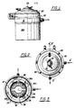
- Fig.1 shows a front elevational view of an oil reclamation device in accordance with the present invention;
- Fig.2 shows a top plan view of the oil reclamation device of Fig.1;
- Fig.3 shows a top plan view of the evaporator plate of the arrangement of Fig.1 with the evaporator plate removed;
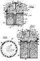
- Fig.4 shows a sectional view taken along line 4'-4' of Fig.2;
- Fig.5 shows a sectional view taken along line 5'-5' of Fig.2; and
- Fig.6 shows a top plan view of the spin on filter of the device.
- Referring now to the drawings, the preferred embodiment and best mode of the invention is shown by Figs.1 to 6.
- The reclamation device, generally designated 10, and most clearly shown in Figures 1, 4 and 5 has an
evaporator plate 12 provided with aninlet 14 and oil inlet channel or bore 15. A 40micron screen 16 is mounted inchannel 15 to provide the first filtering of oil as it enters the device. Theevaporator plate 12 has an integrally formednipple member 18 which is threaded at 19 on its exterior to receive thefilter assembly housing 20. A metering jet 22 is mounted inbore 15 of the threaded nipple to direct fluid into acentral bore 29 of adistribution tube 24 of the filter at a predetermined rate. All of the oil received is introduced directly into the filter assembly via thedistribution tube 24. - A spin on
filter canister 120 is mounted on thenipple 18 and defines a mechanical filtration zone which receives all of the oil coming into the reclamation device 10. The filter assembly includes compressedfibrous filter material 26 contained within thecanister 120. Various conventional filter materials may be used in combination with other features of the invention as are further disclosed in the description of the invention. -
Evaporator plate 12 is disposed adjacent the mechanical filtration zone defined by the filtering mechanism.Plate 12 which is constructed of a special aluminium alloy includes a plurality of integrally formed upwardly projecting sectionedevaporation walls surface 31 on the innermost annular sectionedwall 30 faces inwardly toward the centre of the device. Afluid travelling surface 33 is formed between the spaced vaporizing surfaces of sectionedwalls - An "O"
ring 34 is seated inannular channel 35 cut in the plate surface facing the evaporator head and envelopes the outer peripheral edge ofplate 12. the resilientannular seal 34 is composed of a nitril rubber such as Buna-N which is an oil resistant rubber. - The fluid traveling surfaces defined between sectioned
walls walls evaporator chamber 40. Thus, the longest possible traveling time for the oil from the centermost portion of the evaporator plate to theoil outlet 114 is attained. - The innermost annular sectioned
wall 30 surrounds heater member 52 and has a plurality of throughgoing bores 36 allowing oil to flow from the filter through theevaporator plate 12 into theevaporation chamber 40 adjacent heater member 52. As further shown in this embodiment, the initialfluid traveling surface 31 is defined along an incline extending downwardly toward the heater member 52 surface. - The bores or
passageways 36 extend throughplate 12 and deliver substantially all of the oil from the filter zone to a centermost surface ofplate 12 bounded bywall 30 sections 30a and 30b. Thepassageways 36 take the form of a conical bore and extend from adjacent the mechanical filtration zone where they have their widest cross-section and open outwardly along the upwardly directedoil introducing surface 31 where they have their narrowest cross-section.Oil introducing surface 31 is inclined inwardly with respect to the centermost portion ofplate 12 to direct all of the oil in a thin film downwardly over the vaporizing surface toward theheater element 60 held in member 52. - The sectioned
wall 30 comprises two sections 30a and 30b divided by afluid flow path 37 which leads intoevaporation surface 33. The adjacent sectionedwall 32 also comprises two sections 32a and 32b which form twofluid flow paths 38 positioned perpendicular to thefirst flow path 37. Thefluid flow paths 38 lead toevaporator plate surface 39 which communicates withoutlet 114. This configuration is most clearly shown by Figure 3 of the drawings. - Nuts or screws 60 or any suitable fastening means known in the art are used to join
evaporator head 50 andevaporator plate 12 together. - The
evaporator head 50 which is constructed of a special aluminum alloy includes a heat transmitting member 52 disposed on one side facing the evaporator plate and a heatmember retainer cavity 58 formed in the opposite side. Heat transmitting member 52 is disposed adjacent the center surface ofevaporator plate 12 and engages the plate surface. Theevaporator head 50 in addition to having downwardly projecting member 52 has downwardly projectingheating wall members 54 and 56 which define a plurality of curved heating surfaces. Wall member 54 is located between the sectionedevaporator plate walls wall member 56 is located outside ofevaporator wall 32. - The
heating wall members 52, 54 and 56 of the evaporator head and theevaporation plate walls evaporator plate 12. Thus, the evaporator plate sectionedwalls heating wall members 52, 54 and 56 provide a structural configuration effective to guide the oil from the centermost portion ofplate 12 outwardly along the curved paths to theoil outlet 114. - The
evaporator head 50 defines theheating wall members 52, 54 and 56, on the side facing the evaporator plate, and acavity 58 on the other or cap side receives theheating element 60. Theheating element 60 is constructed of stainless steel for longevity and safety and is connected directly to a power source not shown by the electrical leads 62. Theheating element 60 andcavity 58 are both constructed to get as snug a fit as possible to provide surface to surface contact between theheating element 60 and inside wall of thecavity 58 for conducting heat through the evaporator head to maintain a proper temperature in theevaporation chamber 40 to accelerate vaporization of fuel and water from the oil. - A
cap member 70 is mounted to the outer surface of the evaporator head to covercavity 58 and theheating element 60 mounted therein and maintains the heating element in a hermetically sealed environment. Thecap member 70 is provided with an aperture which allowselectric lead wires 62 to engage the heating element. Screws or machine bolts 72 are used to interconnect thecap member 70 to the evaporator head in a well known fashion. Anappropriate ring gasket 34 can be placed between the abutting surfaces of the evaporator plate and evaporator head to accomplish the desired sealing results if such is required. Avent assembly 76 having a fitting 78 is mounted to a vent bore 55 cut in the evaporator head and is used to allow vapors to escape from theevaporation chamber 40 during the operation of the reclamation device 10. - The heat transmitting center member 52 of the evaporator head extends downwardly within the
evaporation chamber 40 and is substantially surrounded by the innermost annular sectionedwall 30. Center member 52 defines a heating surface located adjacent and facing outwardly toward the inwardly facing vaporizingsurface 31 of sectionedwall 30. Center member 52 seats on the flat surface of the evaporator plate defined between the inner surface of sectionedwall 30. The remaining fluid transmitting sectionedwall 32 also is in contact with the heated fluid traveling alongsurface 37. By this configuration, heat is transmitted via convection and conduction within the evaporation chamber. - The
evaporator head 50 also includes an upper curved body 51 from which theannular walls 54 and 56 extend. Bracket members 53 are integrally formed to the body 51 and extend outward to form mounting ears for the reclamation device. - The downwardly extending annular wall 54 prevents the condensation of vaporized material inside the evaporation chamber. All of the vaporized contaminates are forced through the single evacuation bore 55 located adjacent the vapor vent outlet. Thus the vapors are quickly and efficiently ducted out before they can recondense, as occurs inside an engine crankcase. Annular wall 54 is sufficiently long to prevent the vaporized volatiles from flowing back into the engine.
Wall 56 also maintains the fluid flow of oil down the evaporation wall members of theevaporator plate 12. -
Evaporator plate 12 is provided with a vaporizing surface 31a disposed upwardly and facing inwardly toward center member 52. Oil moves through the conical bores orpassageways 36 and flows in a thin film downwardly along vaporizingsurface 31 and 31a toward thefluid flow path 37 located between the radially disposed annular sectioned walls 30a and 30b as shown in Figure 3. While the oil is in a thin film, the heat transmitted from center member 52 vaporizes the volatile contaminates such as water and fuel which have become entrapped in the lubricating oil during its use. Because of the thin film, water will evaporate at less than 100°C (212°F) and fuel will evaporate at less than flash point. - The filter side of
evaporator plate 12 includes an annularly configured channel seat 17 for receiving a sealing member orgasket 90 disposed betweenevaporator plate 12 and the filter assembly. Sealingmember 90 is located along the entire periphery ofevaporator plate 12 to prohibit the bypassing of fluids betweenplate 12 and thecanister 120. - The oil discharging mechanism of the filter is located in the
upper end portion 84 ofcanister 120. The upper end portion is formed with a recessedconfiguration 85 and a threaded centralfemale receptacle 86 which receivesevaporator plate nipple 18 to hold the filter in place on the evaporator plate. Theupper end portion 84 is also crimped at its periphery to form aseal channel 88 which holds sealingmember 90 in place together with channel seat 17 of the evaporator plate. Spacedradial openings 87 located in theupper end portion 84 enable all of the oil to be directed from the filter toward thepassageways 36 and into theevaporation chamber 40. - The unique filter assembly of this embodiment includes a
removable filter canister 120 in which fibrous filter material such as long strand cotton fiber material is compressed under pressure of up to 7000 pounds per square inch (48.26 x 10⁶ Nm⁻². The cotton material absorbs sulfur thereby neutralizing acids which paper cannot do. It is also envisioned that plastic fibers be mixed with the cotton fibers to provide an anti oxidant when the oil is broken down by heat shear or that the cotton fibers can be impregnated with an oxygen inhibitor. Oxidation of oil can produce thickening and lead to inadequate lubrication. The oxidation of the oil results from the reaction of oil at high temperature with oxygen. A single molecule of oxygen can initiate a series of reactions involving peroxides which result in the oxidation of hydrocarbon molecules. Thus an oxygen inhibiter such as calcium phenate, any of a group of hindered phenols, such as an overbased sulfonate, or aromatic amine is imbedded in polypropylene or suitable plastic strands that will melt at a predetermined temperature releasing the oxidation inhibitors which will immediately function to reduce oxidation.Canister 120 has abottom end portion 80, a side wall portion 82 and anupper end portion 84. It is constructed of a material that is impervious to fluids. - Figures 4 and 5 show the device 10 sectionally with the flow of oil indicated by arrows. Oil enters
oil inlet 14, passes downpassageway 15, is metered by flow meter 22 and continues flowing downdistribution tube 24 of the spin onfilter 120. The oil exits center tube throughoutlets 25 so that it is discharged laterally along thebottom end portion 80 and is forced upward throughfibrous material 26 thereby removing particles down to one micron diameter from the oil. The metering jet 22 incenter tube 24 slows the oil flow to a measured flow rate thus permitting maximum retension by the fibrous material of solid contaminants such as carbon, varnish, gums, metal particles, sludge, silica and dirt. The oil continues upward through theholes 87 of thetop section 84 and then rises through sectionedwall 30 viaholes 36. The oil flows down into the circular area defined by wall sections 30a and 30b into anannular area 33 defined by wall sections 32a and 32b and out intoexit tube 114. -
Heater 60heats evaporator head 50 and causes the oil to vaporize out the liquid impurities as it travels around the respective walls and chamber areas previously ennumerated. - Spin on
filter 120 is attached toevaporator head 12 by threadably mountingnipple 18 into receivingsocket 86 of the spin on filter. - Figure 3 shows the top plan view of the
evaporator plate 12 with the evaporator head removed. -
Bolts 60 tighten theevaporator head 50 downwardly onto the upper peripheral edge of theevaporator plate 12. Theseal 90 has been previously positioned by screwing thecanister 120 to the evaporator plate nipple. Once thebolts 60 are tightened, the various parts of the device are firmly in place and the resultant controlled flow of oil through the reclaimation device 10 provides the greatest amount of filtration and evaporation of contaminates. - In operation the impure oil containing impurities such as carbon, dirt, silica, water, sulphuric acid (H₂SO₄), fuel and the like enters the oil refiner 10 by way of
oil inlet 14 through a 40micron screen 16 andplate channel 15 into the metering jet 22, The metering jet 22 regulates the rate of flow of the fluid along thedistribution tube 24 and out circumferentially positionedholes 25 in thedistribution tube 24 at the bottom of the filter into thefiltering media 26. Due to the pressure maintained by the oil pump of the internal combustion engine the oil works its way up through thefiltering media 26 through theapertures 87 of thefilter perforation plate 84 uppassageways 36 of the evaporator plate into thevaporization chamber 40. The solid impurities such as dirt, silica, dust and carbon particles have been captured by themicron screen 16 andfiltering media 26 respectively. Since the oil and liquid contaminates have different densities, the two became separate as they engage the heated chamber walls and pass over the various baffles formed by those walls. The liquid contaminates such as water, fuel and sulphuric acid vaporize and are carried off byvent 78. Thewalls oil outlet 114 to the crank case for reuse as a lubricant. This is a continuous process which removes the solid and liquid contaminates on each cycling of the oil. Thus the system allows a greater time and milage interval between oil changes, improves gas milage and insures continuous removal of liquid as well as solid contaminentes. - While the description of the invention and the operation has been addressed in terms of oil purification, the term oil could emphasize hydraulic fluid or any other lubrication or fluid which requires cleaning to maintain its original purpose and effectiveness.
Claims (8)
- A fluid reclamation device for filtering solid and liquid impurities from fluid, comprising:
a removable filter assembly (20), with a housing (120) including a cylindrical body and a bottom wall (80) secured to said cylindrical body, said housing containing fibrous material,
a perforated cover plate (84) covering said housing (120),
an evaporator plate (12) mounted to said cover plate, the opposing surfaces of said evaporator plate (12) and cover plate (84) forming a fluid receiving chamber,
attachment means (86) between the perforated cover plate (84) and the evaporator plate (12),
an evaporator head (50), mounted to the evaporator plate (12) by fastening means, and forming an evaporation chamber (40) of the baffled type, having baffles defined therein, between the evaporator head and the evaporator plate (12),
heater means (60) mounted in said evaporator head (50) for heating the fluid circulating along the baffles in the evaporation chamber (40) causing vaporization of liquid impurities in the fluid,
vent means (78) venting said evaporation chamber and mounted to said evaporator head (50),
a fluid passageway, comprising fluid inlet means (14), a fluid distribution tube (24) in communication with said inlet means (14) and which extends between said cover plate means (84) and said bottom (80), allowing fluid to be distributed into said filter assembly housing adjacent said bottom wall (80), fluid openings (87) in the perforated cover plate means (84) leading to said fluid receiving chamber, a fluid passage formed in the evaporator plate leading from said receiving chamber into said evaporation chamber (40), a fluid outlet means (114) formed in the evaporator head (50) providing fluid communication from the evaporation chamber (40) to a fluid reuse means,
said attachment means (86) comprising a threaded female socket member (19) which is centrally positioned in the cover plate means (84) and a threaded nipple (18) integral with the evaporator plate (12) and extending in said socket member (19),
said distribution tube (24) is formed integrally with said socket member (19) and engages the bottom wall (80). - A reclamation device as claimed in claim 1, wherein;
the heater means (60) is mounted in a cavity (58) formed in said evaporator head (50), and cap means (70) covering said heater means (60) is mounted to said evaporation head (50). - A reclamation device as claimed in any of the preceding claims, wherein said evaporation chamber of the baffled type has annular walls (3, 32) which define a plurality of curved portions along a fluid travelling orifice from a longitudinal centre axis outwardly along the evaporator plate (12).
- A reclamation device as claimed in any preceding claim, characterised in that said filter assembly (20) is a spin on filter (120) threadably attached to said evaporator plate (12).
- A reclamation device as claimed in any of the preceding claims, characterised in that said filter assembly contains fibrous filter material comprising cotton fibre, which includes plastic fibre which breaks down at a predetermined temperature to release an oxygen inhibitor.
- A reclamation device as claimed in claim 5, characterised in that said oxygen inhibitor comes from a group consisting of hindered phenols and aromatic amines.
- A reclamation device as claimed in any one of the preceding claims, characterised in that said fluid inlet tube (24) defines a central bore (29) and a plurality of radial throughgoing bores (25) extending through the tube from the central bore to the exterior of the tube, said fluid inlet tube having a distal end that is flared outward and engages the bottom wall of the filter housing.
- A reclamation device as claimed in any of the preceding claims, wherein said evaporator plate (12) has a body of circular configuration and defines a fluid inlet channel (15) which extends into the threaded nipple means (18) extending outwardly from the bottom of the evaporator plate body, the centre axis of said nipple means being axially aligned with the centre of said circulate evaporator plate (12).
Priority Applications (1)
| Application Number | Priority Date | Filing Date | Title |
|---|---|---|---|
| AT88305427T ATE87708T1 (en) | 1987-06-15 | 1988-06-14 | LUBRICATION OIL RECOVERY DEVICE. |
Applications Claiming Priority (4)
| Application Number | Priority Date | Filing Date | Title |
|---|---|---|---|
| US6182387A | 1987-06-15 | 1987-06-15 | |
| US61823 | 1987-06-15 | ||
| US202248 | 1988-06-06 | ||
| US07/202,248 US4943352A (en) | 1987-06-15 | 1988-06-06 | Oil reclamation device |
Publications (3)
| Publication Number | Publication Date |
|---|---|
| EP0295871A2 EP0295871A2 (en) | 1988-12-21 |
| EP0295871A3 EP0295871A3 (en) | 1990-05-23 |
| EP0295871B1 true EP0295871B1 (en) | 1993-03-31 |
Family
ID=26741528
Family Applications (1)
| Application Number | Title | Priority Date | Filing Date |
|---|---|---|---|
| EP88305427A Expired - Lifetime EP0295871B1 (en) | 1987-06-15 | 1988-06-14 | Oil reclamation device |
Country Status (8)
| Country | Link |
|---|---|
| US (1) | US4943352A (en) |
| EP (1) | EP0295871B1 (en) |
| JP (1) | JP2643989B2 (en) |
| CA (1) | CA1317902C (en) |
| DE (1) | DE3879768D1 (en) |
| DK (1) | DK324988A (en) |
| ES (1) | ES2039623T3 (en) |
| NZ (1) | NZ225012A (en) |
Cited By (1)
| Publication number | Priority date | Publication date | Assignee | Title |
|---|---|---|---|---|
| US7862714B2 (en) | 2004-09-24 | 2011-01-04 | Greenoil Standard Aps | Reclamation unit for a liquid |
Families Citing this family (35)
| Publication number | Priority date | Publication date | Assignee | Title |
|---|---|---|---|---|
| US5112482A (en) * | 1989-09-07 | 1992-05-12 | Exxon Research And Engineering Company | Filter for removing hydroperoxides from lubricating oils |
| WO1992002287A1 (en) * | 1990-08-09 | 1992-02-20 | Stokes, Jack, A. | Oil reclaiming device |
| GB9018558D0 (en) * | 1990-08-23 | 1990-10-10 | Ricardo Group Plc | Valve gear for internal combustion engines |
| US5242034A (en) * | 1991-10-17 | 1993-09-07 | Southeast Capital Financing Inc. | Oil reclamation device |
| US5322596A (en) * | 1992-12-30 | 1994-06-21 | Premo Lubrication Technologies, Inc. | Apparatus for removing solid and volatile contaminants from liquids |
| WO1994017146A1 (en) * | 1993-01-29 | 1994-08-04 | Pentel Kabushiki Kaisha | Water color ink having metallic luster for ball-point pens |
| US5942127A (en) * | 1993-09-21 | 1999-08-24 | Wilcox; Steven Ian | Fuel oil treatment unit and associated method |
| JP3312214B2 (en) * | 1994-05-27 | 2002-08-05 | ぺんてる株式会社 | Aqueous metallic glossy ink |
| US5707515A (en) * | 1994-11-22 | 1998-01-13 | Depaul; Michael T. | Lubricating oil reconditioning system with electrically heated platen |
| ZA96680B (en) * | 1995-01-31 | 1996-10-30 | Tf Purifiner Inc | Oil reclamation device with evaporator base and head connected filter |
| US5824211A (en) * | 1995-05-03 | 1998-10-20 | Charles A. Lowry | Oil reclamation device |
| US5630956A (en) * | 1995-06-20 | 1997-05-20 | Certified Technologies Corporation | Oil filtering and refining device |
| TW332217B (en) * | 1995-09-08 | 1998-05-21 | Sakura Color Prod Corp | Ink composition with metallic gloss for marker use |
| US5753120A (en) * | 1995-11-01 | 1998-05-19 | Parker-Hannifin Corporation | Tubular filter element having a sealing arrangement with a housing post |
| GB2309174A (en) * | 1996-01-22 | 1997-07-23 | Richard Henry Howard Barr | Oil reclamation device |
| AU4573697A (en) * | 1996-12-12 | 1998-07-03 | Mitsubishi Pencil Kabushiki Kaisha | Water-base ballpoint ink having metallic glossy color |
| US6955754B2 (en) * | 1997-04-07 | 2005-10-18 | De Sylva Robert | Compact fluid cleaning system |
| US5776315A (en) * | 1997-04-09 | 1998-07-07 | Charles Andrew Lowry | Oil reclamation device |
| US5843284A (en) * | 1997-05-02 | 1998-12-01 | Paul J. T. Waters | Two-stage oil bypass filter device |
| US5900155A (en) * | 1997-05-29 | 1999-05-04 | K.J. Manufacturing Co. | Method and apparatus for reconditioning oil of vehicles |
| US6053143A (en) * | 1998-05-26 | 2000-04-25 | 709398 Ontario Ltd. | Method of improving combustion efficiency and reducing exhaust emissions by controlling oil volatility in internal combustion engines |
| AU2001259213A1 (en) * | 2000-04-28 | 2001-11-12 | Puradyn Filter Technologies Incorporated | Improved filtration efficiency |
| US6818046B1 (en) | 2000-07-21 | 2004-11-16 | Charles Andrew Lowry | Liquid purifying device |
| DE10107035A1 (en) * | 2001-02-15 | 2002-08-22 | Mann & Hummel Filter | Process for filtering oils comprises heating an oil stream to a higher temperature using a heating element before passage through the filter medium |
| DE10310452B4 (en) * | 2003-03-07 | 2008-08-28 | Hengst Gmbh & Co.Kg | Method for treating the crankcase ventilation gas of an internal combustion engine |
| US7513937B2 (en) | 2005-07-08 | 2009-04-07 | Refined Global Solutions, Inc. | Oil reconditioning device and associated methods |
| CN100502998C (en) * | 2005-08-05 | 2009-06-24 | 许巴莱 | Engine oil reduction device |
| SE527777C2 (en) | 2005-10-10 | 2006-06-07 | Cot Clean Oil Techology Ab | Oil purification device for e.g. vehicle engine oil contaminated with water, contains spot heat source for heating contaminant |
| US7396473B1 (en) * | 2007-09-06 | 2008-07-08 | Guynn Stacy D | Engine oil filter |
| US7976702B2 (en) * | 2007-11-30 | 2011-07-12 | Next Generation Filtration Systems, Lp | Fluid purification systems and methods |
| US8298419B2 (en) * | 2010-03-25 | 2012-10-30 | Puradyn Filter Technologies, Inc. | Multi filter lubricant purification system |
| US20100044207A1 (en) * | 2008-08-22 | 2010-02-25 | Innova Enterprises, Inc. | Liquid refining device |
| US20100084255A1 (en) * | 2008-10-06 | 2010-04-08 | Tao Group, Inc. | Liquid purifying device |
| GB0903766D0 (en) * | 2009-03-05 | 2009-04-15 | Maintech Internat Ltd | Fluid reconditioning system |
| EP2347813A1 (en) * | 2010-01-26 | 2011-07-27 | Union Key S.R.L. | Device for filtering motor oil along with blow-by vapours treatment |
Family Cites Families (15)
| Publication number | Priority date | Publication date | Assignee | Title |
|---|---|---|---|---|
| US1718800A (en) * | 1926-05-17 | 1929-06-25 | John G Rea | Oil purifier and gas separator for internal-combustion engines |
| US2839196A (en) * | 1955-08-09 | 1958-06-17 | William C Schwalger | Oil reclaimer |
| US3749247A (en) * | 1970-09-21 | 1973-07-31 | Phillips Petroleum Co | Addition of oxidation inhibitor to lubricating oil |
| US3616885A (en) * | 1970-12-02 | 1971-11-02 | Glen R Priest | Oil reclaimer |
| US3756412A (en) * | 1971-12-02 | 1973-09-04 | G Barrow | Removing contaminants from a fluid stream |
| US3912631A (en) * | 1972-06-09 | 1975-10-14 | William C Turman | Oil filter and adapter |
| US4227969A (en) * | 1977-11-18 | 1980-10-14 | Engel Gary C | Oil reclamation device |
| US4289583A (en) * | 1977-11-18 | 1981-09-15 | Engel Gary C | Oil reclamation device |
| US4189351A (en) * | 1977-11-18 | 1980-02-19 | Engel Gary C | Oil reclamation device |
| US4146475A (en) * | 1977-12-01 | 1979-03-27 | Forsland Audre C | Electrefiner |
| US4297212A (en) * | 1980-06-09 | 1981-10-27 | Padgett Sr Henry A | Oil filter unit |
| US4349438A (en) * | 1981-07-08 | 1982-09-14 | Sims Oil, Inc. | Oil refiner |
| US4354946A (en) * | 1981-07-22 | 1982-10-19 | Frank M. Warlick | Oil reconditioning apparatus and method |
| US4369110A (en) * | 1981-08-13 | 1983-01-18 | David L. Priest | Oil filter for use on internal combustion engines |
| JPS6028530B2 (en) * | 1982-02-26 | 1985-07-05 | 東洋興産株式会社 | Marine engine oil purification method |
-
1988
- 1988-06-06 US US07/202,248 patent/US4943352A/en not_active Expired - Fee Related
- 1988-06-14 NZ NZ225012A patent/NZ225012A/en unknown
- 1988-06-14 ES ES198888305427T patent/ES2039623T3/en not_active Expired - Lifetime
- 1988-06-14 DE DE8888305427T patent/DE3879768D1/en not_active Expired - Lifetime
- 1988-06-14 EP EP88305427A patent/EP0295871B1/en not_active Expired - Lifetime
- 1988-06-14 DK DK324988A patent/DK324988A/en not_active Application Discontinuation
- 1988-06-15 JP JP63147888A patent/JP2643989B2/en not_active Expired - Lifetime
- 1988-06-15 CA CA000569585A patent/CA1317902C/en not_active Expired - Fee Related
Cited By (1)
| Publication number | Priority date | Publication date | Assignee | Title |
|---|---|---|---|---|
| US7862714B2 (en) | 2004-09-24 | 2011-01-04 | Greenoil Standard Aps | Reclamation unit for a liquid |
Also Published As
| Publication number | Publication date |
|---|---|
| NZ225012A (en) | 1991-01-29 |
| DK324988D0 (en) | 1988-06-14 |
| CA1317902C (en) | 1993-05-18 |
| DE3879768D1 (en) | 1993-05-06 |
| EP0295871A3 (en) | 1990-05-23 |
| US4943352A (en) | 1990-07-24 |
| JP2643989B2 (en) | 1997-08-25 |
| EP0295871A2 (en) | 1988-12-21 |
| DK324988A (en) | 1988-12-16 |
| JPS6456109A (en) | 1989-03-03 |
| ES2039623T3 (en) | 1993-10-01 |
Similar Documents
| Publication | Publication Date | Title |
|---|---|---|
| US4943352A (en) | Oil reclamation device | |
| US5242034A (en) | Oil reclamation device | |
| US5843284A (en) | Two-stage oil bypass filter device | |
| AU735597B2 (en) | Lubricating oil reconditioning system | |
| AU679720B2 (en) | Apparatus for removing solid and volatile contaminants from liquids | |
| US4289583A (en) | Oil reclamation device | |
| EP0858825A1 (en) | Fuel filter with air vent | |
| US5630912A (en) | Oil reclamation device with evaporator base and head mounted filter | |
| JPH0647051B2 (en) | Oil cleaning assembly for engine | |
| US20020046965A1 (en) | Compact fluid cleaniing system | |
| US4338189A (en) | Oil reconditioning device | |
| WO2008045849A1 (en) | Oil purifier system and process | |
| AU616890B2 (en) | Improved oil reclamation device | |
| EP0547896A2 (en) | Reclamation device | |
| US6818046B1 (en) | Liquid purifying device | |
| US5707515A (en) | Lubricating oil reconditioning system with electrically heated platen | |
| WO1984001112A1 (en) | Oil refiner with separable vaporization and filtering elements | |
| KR930006397B1 (en) | Oil Refinery with Spray Nozzle | |
| WO1992002287A1 (en) | Oil reclaiming device | |
| US20050040077A1 (en) | Lubricating oil reconditioning device and process | |
| KR200142393Y1 (en) | Oil filter | |
| CA2082253A1 (en) | Oil reclaiming device | |
| GB2329850A (en) | Liquid filter with slot shaped air vent |
Legal Events
| Date | Code | Title | Description |
|---|---|---|---|
| PUAI | Public reference made under article 153(3) epc to a published international application that has entered the european phase |
Free format text: ORIGINAL CODE: 0009012 |
|
| AK | Designated contracting states |
Kind code of ref document: A2 Designated state(s): AT BE CH DE ES FR GB GR IT LI LU NL SE |
|
| RAP1 | Party data changed (applicant data changed or rights of an application transferred) |
Owner name: PURIFINER DISTRIBUTION CORPORATION |
|
| PUAL | Search report despatched |
Free format text: ORIGINAL CODE: 0009013 |
|
| AK | Designated contracting states |
Kind code of ref document: A3 Designated state(s): AT BE CH DE ES FR GB GR IT LI LU NL SE |
|
| 17P | Request for examination filed |
Effective date: 19901116 |
|
| 17Q | First examination report despatched |
Effective date: 19910131 |
|
| GRAA | (expected) grant |
Free format text: ORIGINAL CODE: 0009210 |
|
| RAP1 | Party data changed (applicant data changed or rights of an application transferred) |
Owner name: SOUTHEAST CAPITAL FINANCING, INC. |
|
| AK | Designated contracting states |
Kind code of ref document: B1 Designated state(s): AT BE CH DE ES FR GB GR IT LI LU NL SE |
|
| PG25 | Lapsed in a contracting state [announced via postgrant information from national office to epo] |
Ref country code: GR Free format text: LAPSE BECAUSE OF FAILURE TO SUBMIT A TRANSLATION OF THE DESCRIPTION OR TO PAY THE FEE WITHIN THE PRESCRIBED TIME-LIMIT Effective date: 19930331 Ref country code: DE Effective date: 19930331 Ref country code: AT Effective date: 19930331 |
|
| REF | Corresponds to: |
Ref document number: 87708 Country of ref document: AT Date of ref document: 19930415 Kind code of ref document: T |
|
| REF | Corresponds to: |
Ref document number: 3879768 Country of ref document: DE Date of ref document: 19930506 |
|
| ET | Fr: translation filed | ||
| ITF | It: translation for a ep patent filed | ||
| PG25 | Lapsed in a contracting state [announced via postgrant information from national office to epo] |
Ref country code: SE Effective date: 19930615 Ref country code: ES Free format text: LAPSE BECAUSE OF EXPIRATION OF PROTECTION Effective date: 19930615 |
|
| PG25 | Lapsed in a contracting state [announced via postgrant information from national office to epo] |
Ref country code: LU Free format text: LAPSE BECAUSE OF NON-PAYMENT OF DUE FEES Effective date: 19930630 Ref country code: LI Effective date: 19930630 Ref country code: GB Effective date: 19930630 Ref country code: CH Effective date: 19930630 Ref country code: BE Effective date: 19930630 |
|
| REG | Reference to a national code |
Ref country code: ES Ref legal event code: FG2A Ref document number: 2039623 Country of ref document: ES Kind code of ref document: T3 |
|
| BERE | Be: lapsed |
Owner name: SOUTHEAST CAPITAL FINANCING INC. Effective date: 19930630 |
|
| PG25 | Lapsed in a contracting state [announced via postgrant information from national office to epo] |
Ref country code: NL Effective date: 19940101 |
|
| PLBE | No opposition filed within time limit |
Free format text: ORIGINAL CODE: 0009261 |
|
| STAA | Information on the status of an ep patent application or granted ep patent |
Free format text: STATUS: NO OPPOSITION FILED WITHIN TIME LIMIT |
|
| NLV4 | Nl: lapsed or anulled due to non-payment of the annual fee | ||
| GBPC | Gb: european patent ceased through non-payment of renewal fee |
Effective date: 19930630 |
|
| PG25 | Lapsed in a contracting state [announced via postgrant information from national office to epo] |
Ref country code: FR Effective date: 19940228 |
|
| REG | Reference to a national code |
Ref country code: CH Ref legal event code: PL |
|
| 26N | No opposition filed | ||
| REG | Reference to a national code |
Ref country code: FR Ref legal event code: ST |
|
| EUG | Se: european patent has lapsed |
Ref document number: 88305427.2 Effective date: 19940110 |
|
| REG | Reference to a national code |
Ref country code: ES Ref legal event code: FD2A Effective date: 20000601 |
|
| PG25 | Lapsed in a contracting state [announced via postgrant information from national office to epo] |
Ref country code: IT Free format text: LAPSE BECAUSE OF NON-PAYMENT OF DUE FEES;WARNING: LAPSES OF ITALIAN PATENTS WITH EFFECTIVE DATE BEFORE 2007 MAY HAVE OCCURRED AT ANY TIME BEFORE 2007. THE CORRECT EFFECTIVE DATE MAY BE DIFFERENT FROM THE ONE RECORDED. Effective date: 20050614 |