EP0294123B1 - A liquid ink transfer system - Google Patents
A liquid ink transfer system Download PDFInfo
- Publication number
- EP0294123B1 EP0294123B1 EP88304873A EP88304873A EP0294123B1 EP 0294123 B1 EP0294123 B1 EP 0294123B1 EP 88304873 A EP88304873 A EP 88304873A EP 88304873 A EP88304873 A EP 88304873A EP 0294123 B1 EP0294123 B1 EP 0294123B1
- Authority
- EP
- European Patent Office
- Prior art keywords
- charge
- copy sheet
- polarity
- image
- liquid
- Prior art date
- Legal status (The legal status is an assumption and is not a legal conclusion. Google has not performed a legal analysis and makes no representation as to the accuracy of the status listed.)
- Expired - Lifetime
Links
- 239000007788 liquid Substances 0.000 title claims description 63
- 238000012546 transfer Methods 0.000 title description 24
- 239000002245 particle Substances 0.000 claims description 28
- 239000000463 material Substances 0.000 claims description 13
- 150000002500 ions Chemical class 0.000 claims description 7
- 239000007921 spray Substances 0.000 claims description 6
- 239000000758 substrate Substances 0.000 description 8
- 238000004140 cleaning Methods 0.000 description 5
- 238000011161 development Methods 0.000 description 5
- 238000000034 method Methods 0.000 description 3
- 229910001370 Se alloy Inorganic materials 0.000 description 2
- BUGBHKTXTAQXES-UHFFFAOYSA-N Selenium Chemical class [Se] BUGBHKTXTAQXES-UHFFFAOYSA-N 0.000 description 2
- 238000012986 modification Methods 0.000 description 2
- 230000004048 modification Effects 0.000 description 2
- 238000012545 processing Methods 0.000 description 2
- WUPHOULIZUERAE-UHFFFAOYSA-N 3-(oxolan-2-yl)propanoic acid Chemical compound OC(=O)CCC1CCCO1 WUPHOULIZUERAE-UHFFFAOYSA-N 0.000 description 1
- 229910000838 Al alloy Inorganic materials 0.000 description 1
- 230000003213 activating effect Effects 0.000 description 1
- 150000001338 aliphatic hydrocarbons Chemical class 0.000 description 1
- 238000009835 boiling Methods 0.000 description 1
- 229910052980 cadmium sulfide Inorganic materials 0.000 description 1
- 239000006229 carbon black Substances 0.000 description 1
- 230000007547 defect Effects 0.000 description 1
- 238000001962 electrophoresis Methods 0.000 description 1
- 230000005686 electrostatic field Effects 0.000 description 1
- 238000005286 illumination Methods 0.000 description 1
- 239000000049 pigment Substances 0.000 description 1
- 229920000642 polymer Polymers 0.000 description 1
- 238000005507 spraying Methods 0.000 description 1
- 229920003002 synthetic resin Polymers 0.000 description 1
- 239000000057 synthetic resin Substances 0.000 description 1
Images

Classifications
-
- G—PHYSICS
- G03—PHOTOGRAPHY; CINEMATOGRAPHY; ANALOGOUS TECHNIQUES USING WAVES OTHER THAN OPTICAL WAVES; ELECTROGRAPHY; HOLOGRAPHY
- G03G—ELECTROGRAPHY; ELECTROPHOTOGRAPHY; MAGNETOGRAPHY
- G03G15/00—Apparatus for electrographic processes using a charge pattern
- G03G15/14—Apparatus for electrographic processes using a charge pattern for transferring a pattern to a second base
- G03G15/16—Apparatus for electrographic processes using a charge pattern for transferring a pattern to a second base of a toner pattern, e.g. a powder pattern, e.g. magnetic transfer
- G03G15/1665—Apparatus for electrographic processes using a charge pattern for transferring a pattern to a second base of a toner pattern, e.g. a powder pattern, e.g. magnetic transfer by introducing the second base in the nip formed by the recording member and at least one transfer member, e.g. in combination with bias or heat
- G03G15/167—Apparatus for electrographic processes using a charge pattern for transferring a pattern to a second base of a toner pattern, e.g. a powder pattern, e.g. magnetic transfer by introducing the second base in the nip formed by the recording member and at least one transfer member, e.g. in combination with bias or heat at least one of the recording member or the transfer member being rotatable during the transfer
-
- G—PHYSICS
- G03—PHOTOGRAPHY; CINEMATOGRAPHY; ANALOGOUS TECHNIQUES USING WAVES OTHER THAN OPTICAL WAVES; ELECTROGRAPHY; HOLOGRAPHY
- G03G—ELECTROGRAPHY; ELECTROPHOTOGRAPHY; MAGNETOGRAPHY
- G03G15/00—Apparatus for electrographic processes using a charge pattern
- G03G15/14—Apparatus for electrographic processes using a charge pattern for transferring a pattern to a second base
- G03G15/16—Apparatus for electrographic processes using a charge pattern for transferring a pattern to a second base of a toner pattern, e.g. a powder pattern, e.g. magnetic transfer
- G03G15/163—Apparatus for electrographic processes using a charge pattern for transferring a pattern to a second base of a toner pattern, e.g. a powder pattern, e.g. magnetic transfer using the force produced by an electrostatic transfer field formed between the second base and the electrographic recording member, e.g. transfer through an air gap
- G03G15/1635—Apparatus for electrographic processes using a charge pattern for transferring a pattern to a second base of a toner pattern, e.g. a powder pattern, e.g. magnetic transfer using the force produced by an electrostatic transfer field formed between the second base and the electrographic recording member, e.g. transfer through an air gap the field being produced by laying down an electrostatic charge behind the base or the recording member, e.g. by a corona device
Definitions
- This invention relates to an apparatus for transferring a liquid image from a surface to a substantially electrically non-conductive, flexible copy sheet with the liquid image being charged to one polarity and the surface being charged to a polarity opposite to the polarity of the charge of the liquid image, said apparatus comprising charging means for applying a charge on the copy sheet.
- Such an apparatus is especially useful in an electrophotographic printing machine, where a liquid image is transferred from a photoconductive surface to a copy sheet.
- the process of electrophotographic printing includes charging a photoconductive member to a substantially uniform potential to sensitize the surface thereof.
- the charged portion of the photoconductive member is exposed to a light image of an original document being reproduced.
- the latent image is developed by bringing a liquid developer material into contact therewith.
- the liquid developer material is deposited, in image configuration, on the photoconductive member.
- the liquid image is transferred to the copy sheet.
- the liquid image includes residual liquid carrier and pigmented particles. After transfer, heat is applied to the copy sheet to permanently fuse the pigmented particles to the copy sheet and vaporize the residual liquid carrier adhering thereto.
- Transfer of the liquid image to the copy sheet is generally achieved by applying an electrostatic force, in the transfer zone, to overcome the forces holding the liquid image to the photoconductive surface.
- electrostatic forces are usually provided by a corona generating device spraying ions onto the backside of the copy sheet or by an electrically biased roller or belt engaging the backside of the copy sheet in the transfer zone.
- the liquid image is not always completely transferred and smudging or smear of the liquid image often results.
- the electrostatic field and contact pressure are critical. An uneven or non-uniform charge on the copy sheet can cause defects observable in the final image on the copy sheet.
- various techniques have been devised for transferring a toner image to a copy sheet.
- US-A-3 734 724 discloses a process for forming a lithographic plate.
- An electrostatic latent image, recorded on an electrophotographic element, is developed with toner.
- the toner may be a liquid or dry material.
- An electrically conductive receiver is charged to the same polarity as the polarity of the charge of the toner developed on the latent image.
- the receiver is then placed in face-to-face contact with the latent image.
- the charge on the receiver repels the toner preventing the toner image from being disturbed.
- a charge having an opposite polarity is than applied to the receiver to attract the toner image thereto. If the element having the latent image recorded thereon is transparent, the latent image can be flood illuminated so as to be discharged.
- the receiver is used as a lithographic plate.
- US-A-3 966 199 teaches an electrostatographic copying system which utilizes a transport belt to move a copy sheet through a toner transfer station. Guide fingers and a corona generator form a station at which a copy sheet is electrostatically tacked onto the transport belt.
- US-A-4 014 605 discloses a transfer system for an electrophotographic copying machine which employs selective exposure of a photoconductive transfer member. Tailored transfer fields with tailored illumination of a photoconductive material enhances the quality of image transfer from a photoreceptive member to a receiving substrate.
- a system is provided for tacking a copy sheet to a photoconductive transport belt by simultaneously activating a charging device and an illuminating source.
- the present invention is intended to provide an apparatus having improved transfer of a liquid image, and accordingly provides an apparatus of the kind specified which is characterised in that the charging means comprises first means for applying a first charge on the copy sheet with the first charge on the copy sheet being of the same polarity as the polarity of the charge of the liquid image to cause the copy sheet to adhere releasably to the surface with the liquid image being interposed therebetween; and second means for applying a second charge on the copy sheet having the first charge thereon with the second charge on the copy sheet being of an opposite polarity to the polarity of the charge of the liquid image to cause the liquid image to be attracted to the copy sheet.
- an electrophotographic printing machine of the type having an electrostatic latent image recorded on a photoconductive surface.
- the latent image is developed with a liquid developer material to form a liquid image thereon.
- the liquid image is transferred from the photoconductive surface to a substantially non-conductive, flexible copy sheet.
- the liquid image is charged to one polarity and the charge of the photoconductive surface is charged to a polarity opposite to the polarity of the charge of the liquid image.
- First means apply a first charge on the copy sheet.
- the first charge on the copy sheet is of the same polarity as the charge of the liquid image to cause the copy sheet to adhere releasably to the photoconductive surface with the liquid image being interposed therebetween.
- Second means apply a second charge on the copy sheet after the first charge has been applied thereon.
- the second charge on the copy sheet is of an opposite polarity to the charge of the liquid image. This causes the liquid image to be attracted to the copy sheet.
- the electrophotographic printing machine employs a belt 10 having a photoconductive surface deposited on a conductive substrate.
- the photoconductive surface is made from a selenium alloy with the conductive substrate being made from an electrically grounded aluminum alloy.
- Other suitable photoconductive surfaces and conductive substrates may also be employed.
- Belt 10 moves in the direction of arrow 12 to advance successive portions of the photoconductive surface through the various processing stations disposed about the path of movement thereof.
- Belt 10 is supported by three rollers 14, 16, and 18 located with parallel axes at approximately the apexes of a triangle.
- Roller 14 is rotatably driven by a suitable motor associated with a drive (not shown) to move belt 10 in the direction of arrow 12.
- a corona generating device indicated generally by the reference numeral 20, charges the photoconductive surface of belt 10 to a relatively high, substantially uniform potential.
- the charged portion of the photoconductive surface is advanced through exposure station B.
- an original document 22 is positioned face down upon a transparent platen 24. Lamps flash light rays onto original document 22. The light rays reflected from original document 22 are transmitted through a lens forming a light image thereof. The lens focuses the light image onto the charged portion of the photoconductive surface to selectively dissipate the charge thereon. This records an electrostatic latent image on the photoconductive surface corresponding to the informational areas contained within the original document.
- belt 10 advances the electrostatic latent image recorded on the photoconductive surface to development station C.
- a developing liquid comprising an insulating carrier liquid and toner particles, is circulated from any suitable source (not shown) through pipe 26 into development tray 28 from which it is withdrawn through pipe 30 for recirculation.
- Development electrode 32 which may be appropriately electrically biased, assists in developing the electrostatic latent image with the toner particles, i.e. the pigmented particles dispersed in the liquid carrier, as it passes in contact with the developing liquid.
- the charged toner particles, disseminated throughout the carrier liquid pass by electrophoresis to the electrostatic latent image.
- the charge of the toner particles is opposite in polarity to the charge on the photoconductive surface.
- the photoconductive surface is made from a selenium alloy, the photoconductive surface will be positively charged and the toner particles will be negatively charged.
- the photoconductive surface is made from a cadmium sulfide material, the photoconductive surface will be negatively charged and the toner particles will be positively charged.
- the amount of liquid carrier on the photoconductive surface is too great.
- a roller (not shown) whose surface moves in a direction opposite to the direction of movement of the photoconductive surface, is spaced from the photoconductive surface and adapted to shear excessive liquid from the developed image without disturbing the image.
- the developer material includes a liquid insulating carrier having pigmented particles, i.e.
- a suitable insulating liquid carrier may be made from an aliphatic hydrocarbon, such as an isopar, which is a trademark of the Exxon Corporation, having a low boiling point.
- the toner particles include a pigment, such as carbon black, associated with the polymer.
- a suitable liquid developer material is described in US-A-4,582,774.
- belt 10 advances the developed image to transfer station D.
- a sheet of support material 34 i.e. a copy sheet made from a substantially non-conductive paper
- the sheet of support material advances in synchronism with the movement of the developed image on belt 10 so as to arrive simultaneously therewith at transfer station D.
- Transfer station D includes a corona generating device 40 which sprays ions onto the backside of the electrically non-conductive paper 34 to charge the paper to the same polarity as the charge on the toner particles. This charge tacks the copy paper to the photoconductive surface and drives the toner particles toward the photoconductive surface so that the toner image is not disturbed by the copy paper.
- the copy paper, tacked to the photoconductive surface moves beneath corona generating device 41.
- Corona generating device 41 sprays ions onto the backside of the electrically non-conductive paper 34 to charge the paper to a polarity opposite to the polarity of the charge on the toner particles. This attracts the developed toner image from the photoconductive surface to the copy paper.
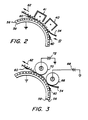
- the detailed structure of the various embodiments of the transfer system will be described hereinafter with reference to Figure 2 and Figure 3. After transfer, the copy paper continues to move onto conveyor 42 which advances the sheet to fusing station E.
- Fusing station E includes a fusing system indicated generally by the reference 44.
- the fuser assembly e.g. a radiant heater, vaporizes the liquid carrier from the copy sheet and permanently fuses the toner particles in image configuration thereto. After fusing, the copy sheet is advanced to catch tray 46 for subsequent removal from the printing machine by the operator.
- Cleaning station F includes a cleaning roller 48, formed of any appropriate synthetic resin driven in a direction opposite to the direction of movement of the photoconductive surface to scrub the photoconductive surface clean. To assist in this action, developing liquid may be fed through pipe 50 onto the surface of cleaning roller 48. A wiper blade 52 completes the cleaning of the photoconductive surface. Any residual charge left on the photoconductive surface is extinguished by flooding the photoconductive surface with light from lamp 54.
- belt 10 having a photoconductive surface 56 coated on a conductive substrate 58.
- Conductive substrate 58 is electrically grounded.
- photoconductive surface 56 is positively charged.
- Toner particles 60 adhering to photoconductive surface 56 in image configuration, are negatively charged.
- Electrically non-conductive copy paper 34 advances in the direction of arrow 62 beneath corona generating device 40.
- Corona generating device 40 sprays ions onto the backside of copy paper 34 to induce a negative charge thereon.
- the negatively charged copy paper is attracted to the positively charged photoconductive surface. In this way, the copy paper is tacked to the photoconductive surface.
- the negative charge on the copy paper repels the negatively charged toner particles.
- the toner particles are driven toward the photoconductive surface and are not disturbed by the tacking of the copy paper thereto.
- the copy paper continues to move in the direction of arrow 62, it passes beneath corona generating device 41.
- Corona generating device 41 sprays ions onto the backside of the copy sheet to induce a positive charge thereon.
- the positively charged copy paper attracts the negatively charged toner particles thereto in image configuration.
- the copy sheet is now repelled from the positively charged photoconductive surface with the toner image adhering thereto.
- Belt 10 has a photoconductive surface 56 coated on a conductive substrate 58.
- Conductive substrate 58 is electrically grounded.
- photoconductive surface 56 is positively charged.
- Toner particles 60, adhering to photoconductive surface 56 in image configuration, are negatively charged.
- Electrically non-conductive copy paper 34 is advanced in the direction of arrow 62.
- Copy paper 34 passes through a nip defined by roller 66 and photoconductive surface 56.
- Roller 66 is electrically connected to voltage source 68.
- Voltage source 68 electrically biases roller 66 to a negative potential.
- the negatively charged copy paper is attracted to the positively charged photoconductive surface. In this way, the copy paper is tacked to the photoconductive surface.
- the negative charge on the copy paper repels the negatively charged toner particles.
- the toner particles are driven toward the photoconductive surface and are not disturbed by the tacking of the copy paper thereto.
- Voltage source 72 electrically biases roller 66 to a positive potential.
- copy paper 34 passes through the nip defined by roller 70 and photoconductive surface 56, it is charged to a positive polarity.
- the negatively charged toner particles are attracted from the photoconductive surface to the positively charged copy sheet, in image configuration.
- the copy sheet is now repelled from the positively charged photoconductive surface with the toner image adhering thereto.
- roller 66 and voltage source 68 of Figure 3 may be used in Figure 2 in lieu of corona generating device 40 of Figure 2.
- corona generating device 41 of Figure 2 may be used in Figure 3 instead of roller 70 and voltage source 72.
- the transfer system of the present invention induces a charge on an advancing electrically non-conductive copy sheet of the same polarity as the charge on the liquid developer adhering to the photoconductive surface.
- This causes the copy sheet to be tacked to the photoconductive surface and the toner particles of the liquid developer to move toward the photoconductive surface.
- the toner image remains undisturbed as the copy sheet is tacked to the photoconductive surface.
- the copy sheet is charged to the opposite polarity so as to attract the toner image thereto. Simultaneously, the copy sheet is repelled from the photoconductive surface so as to be readily removed therefrom.
Landscapes
- Physics & Mathematics (AREA)
- General Physics & Mathematics (AREA)
- Electrostatic Charge, Transfer And Separation In Electrography (AREA)
- Wet Developing In Electrophotography (AREA)
Description
- This invention relates to an apparatus for transferring a liquid image from a surface to a substantially electrically non-conductive, flexible copy sheet with the liquid image being charged to one polarity and the surface being charged to a polarity opposite to the polarity of the charge of the liquid image, said apparatus comprising charging means for applying a charge on the copy sheet. Such an apparatus is especially useful in an electrophotographic printing machine, where a liquid image is transferred from a photoconductive surface to a copy sheet.
- Generally, the process of electrophotographic printing includes charging a photoconductive member to a substantially uniform potential to sensitize the surface thereof. The charged portion of the photoconductive member is exposed to a light image of an original document being reproduced. This records an electrostatic latent image on the photoconductive member corresponding to the informational areas contained within the original document. After the electrostatic latent image is recorded on the photoconductive member, the latent image is developed by bringing a liquid developer material into contact therewith. The liquid developer material is deposited, in image configuration, on the photoconductive member. Thereafter, the liquid image is transferred to the copy sheet. The liquid image includes residual liquid carrier and pigmented particles. After transfer, heat is applied to the copy sheet to permanently fuse the pigmented particles to the copy sheet and vaporize the residual liquid carrier adhering thereto.
- Transfer of the liquid image to the copy sheet is generally achieved by applying an electrostatic force, in the transfer zone, to overcome the forces holding the liquid image to the photoconductive surface. These electrostatic forces are usually provided by a corona generating device spraying ions onto the backside of the copy sheet or by an electrically biased roller or belt engaging the backside of the copy sheet in the transfer zone. The liquid image is not always completely transferred and smudging or smear of the liquid image often results. In order to achieve good transfer of the liquid image, the electrostatic field and contact pressure are critical. An uneven or non-uniform charge on the copy sheet can cause defects observable in the final image on the copy sheet. Hereinbefore, various techniques have been devised for transferring a toner image to a copy sheet.
- US-A-3 734 724 discloses a process for forming a lithographic plate. An electrostatic latent image, recorded on an electrophotographic element, is developed with toner. The toner may be a liquid or dry material. An electrically conductive receiver is charged to the same polarity as the polarity of the charge of the toner developed on the latent image. The receiver is then placed in face-to-face contact with the latent image. The charge on the receiver repels the toner preventing the toner image from being disturbed. A charge having an opposite polarity is than applied to the receiver to attract the toner image thereto. If the element having the latent image recorded thereon is transparent, the latent image can be flood illuminated so as to be discharged. The receiver is used as a lithographic plate.
- US-A-3 966 199 teaches an electrostatographic copying system which utilizes a transport belt to move a copy sheet through a toner transfer station. Guide fingers and a corona generator form a station at which a copy sheet is electrostatically tacked onto the transport belt.
- US-A-4 014 605 discloses a transfer system for an electrophotographic copying machine which employs selective exposure of a photoconductive transfer member. Tailored transfer fields with tailored illumination of a photoconductive material enhances the quality of image transfer from a photoreceptive member to a receiving substrate. A system is provided for tacking a copy sheet to a photoconductive transport belt by simultaneously activating a charging device and an illuminating source.
- The present invention is intended to provide an apparatus having improved transfer of a liquid image, and accordingly provides an apparatus of the kind specified which is characterised in that the charging means comprises first means for applying a first charge on the copy sheet with the first charge on the copy sheet being of the same polarity as the polarity of the charge of the liquid image to cause the copy sheet to adhere releasably to the surface with the liquid image being interposed therebetween; and second means for applying a second charge on the copy sheet having the first charge thereon with the second charge on the copy sheet being of an opposite polarity to the polarity of the charge of the liquid image to cause the liquid image to be attracted to the copy sheet.
- Pursuant to another aspect of the features of the present invention, there is provided an electrophotographic printing machine of the type having an electrostatic latent image recorded on a photoconductive surface. The latent image is developed with a liquid developer material to form a liquid image thereon. The liquid image is transferred from the photoconductive surface to a substantially non-conductive, flexible copy sheet. The liquid image is charged to one polarity and the charge of the photoconductive surface is charged to a polarity opposite to the polarity of the charge of the liquid image. First means apply a first charge on the copy sheet. The first charge on the copy sheet is of the same polarity as the charge of the liquid image to cause the copy sheet to adhere releasably to the photoconductive surface with the liquid image being interposed therebetween. Second means apply a second charge on the copy sheet after the first charge has been applied thereon. The second charge on the copy sheet is of an opposite polarity to the charge of the liquid image. This causes the liquid image to be attracted to the copy sheet.
- Other aspects of the present invention will become apparent as the following description proceeds and upon reference to the drawings, in which:
- Figure 1 is a schematic elevational view showing an illustrative electrophotographic printing machine incorporating the features of the present invention therein;
- Figure 2 is an elevational view depicting one embodiment of a transfer system used in the Figure 1 printing machine; and
- Figure 3 is an elevational view showing another embodiment of the Figure 2 transfer system.
- Inasmuch as the art of electrophotographic printing is well known, the various processing stations employed in the Figure 1 printing machine will be shown hereinafter schematically and their operation described briefly with reference thereto.
- Turning now to Figure 1, the electrophotographic printing machine employs a
belt 10 having a photoconductive surface deposited on a conductive substrate. Preferably, the photoconductive surface is made from a selenium alloy with the conductive substrate being made from an electrically grounded aluminum alloy. Other suitable photoconductive surfaces and conductive substrates may also be employed.Belt 10 moves in the direction ofarrow 12 to advance successive portions of the photoconductive surface through the various processing stations disposed about the path of movement thereof.Belt 10 is supported by threerollers Roller 14 is rotatably driven by a suitable motor associated with a drive (not shown) to movebelt 10 in the direction ofarrow 12. - Initially, a portion of
belt 10 passes through charging station A. At charging station A, a corona generating device, indicated generally by thereference numeral 20, charges the photoconductive surface ofbelt 10 to a relatively high, substantially uniform potential. - Next, the charged portion of the photoconductive surface is advanced through exposure station B. At exposure station B, an
original document 22 is positioned face down upon atransparent platen 24. Lamps flash light rays ontooriginal document 22. The light rays reflected fromoriginal document 22 are transmitted through a lens forming a light image thereof. The lens focuses the light image onto the charged portion of the photoconductive surface to selectively dissipate the charge thereon. This records an electrostatic latent image on the photoconductive surface corresponding to the informational areas contained within the original document. Thereafter,belt 10 advances the electrostatic latent image recorded on the photoconductive surface to development station C. - At development station C, a developing liquid comprising an insulating carrier liquid and toner particles, is circulated from any suitable source (not shown) through
pipe 26 intodevelopment tray 28 from which it is withdrawn throughpipe 30 for recirculation.Development electrode 32, which may be appropriately electrically biased, assists in developing the electrostatic latent image with the toner particles, i.e. the pigmented particles dispersed in the liquid carrier, as it passes in contact with the developing liquid. The charged toner particles, disseminated throughout the carrier liquid, pass by electrophoresis to the electrostatic latent image. The charge of the toner particles is opposite in polarity to the charge on the photoconductive surface. By way of example, if the photoconductive surface is made from a selenium alloy, the photoconductive surface will be positively charged and the toner particles will be negatively charged. Alternatively, if the photoconductive surface is made from a cadmium sulfide material, the photoconductive surface will be negatively charged and the toner particles will be positively charged. Generally, the amount of liquid carrier on the photoconductive surface is too great. A roller (not shown) whose surface moves in a direction opposite to the direction of movement of the photoconductive surface, is spaced from the photoconductive surface and adapted to shear excessive liquid from the developed image without disturbing the image. Preferably, the developer material includes a liquid insulating carrier having pigmented particles, i.e. toner particles dispersed therein A suitable insulating liquid carrier may be made from an aliphatic hydrocarbon, such as an isopar, which is a trademark of the Exxon Corporation, having a low boiling point. The toner particles include a pigment, such as carbon black, associated with the polymer. A suitable liquid developer material is described in US-A-4,582,774. - After development,
belt 10 advances the developed image to transfer station D. At transfer station D, a sheet ofsupport material 34, i.e. a copy sheet made from a substantially non-conductive paper, is advanced fromstack 36 by a sheet feeder, indicated generally by thereference numeral 38. The sheet of support material advances in synchronism with the movement of the developed image onbelt 10 so as to arrive simultaneously therewith at transfer station D. Transfer station D includes acorona generating device 40 which sprays ions onto the backside of the electricallynon-conductive paper 34 to charge the paper to the same polarity as the charge on the toner particles. This charge tacks the copy paper to the photoconductive surface and drives the toner particles toward the photoconductive surface so that the toner image is not disturbed by the copy paper. The copy paper, tacked to the photoconductive surface moves beneathcorona generating device 41.Corona generating device 41 sprays ions onto the backside of the electricallynon-conductive paper 34 to charge the paper to a polarity opposite to the polarity of the charge on the toner particles. This attracts the developed toner image from the photoconductive surface to the copy paper. The detailed structure of the various embodiments of the transfer system will be described hereinafter with reference to Figure 2 and Figure 3. After transfer, the copy paper continues to move ontoconveyor 42 which advances the sheet to fusing station E. - Fusing station E includes a fusing system indicated generally by the reference 44. The fuser assembly, e.g. a radiant heater, vaporizes the liquid carrier from the copy sheet and permanently fuses the toner particles in image configuration thereto. After fusing, the copy sheet is advanced to catch
tray 46 for subsequent removal from the printing machine by the operator. - After the copy sheet is separated from the photoconductive surface of
belt 10, some residual liquid developer material remains adhering thereto. This residual developer material is removed from the photoconductive surface at cleaning station F. Cleaning station F includes a cleaningroller 48, formed of any appropriate synthetic resin driven in a direction opposite to the direction of movement of the photoconductive surface to scrub the photoconductive surface clean. To assist in this action, developing liquid may be fed throughpipe 50 onto the surface of cleaningroller 48. Awiper blade 52 completes the cleaning of the photoconductive surface. Any residual charge left on the photoconductive surface is extinguished by flooding the photoconductive surface with light fromlamp 54. - It is believed that the foregoing description is sufficient for purposes of the present application to illustrate the general operation of an electrophotographic printing machine incorporating the features of the present invention therein.
- Referring now to Figure 2, there is shown
belt 10 having aphotoconductive surface 56 coated on aconductive substrate 58.Conductive substrate 58 is electrically grounded. As depicted,photoconductive surface 56 is positively charged.Toner particles 60, adhering tophotoconductive surface 56 in image configuration, are negatively charged. Electricallynon-conductive copy paper 34 advances in the direction ofarrow 62 beneathcorona generating device 40.Corona generating device 40 sprays ions onto the backside ofcopy paper 34 to induce a negative charge thereon. The negatively charged copy paper is attracted to the positively charged photoconductive surface. In this way, the copy paper is tacked to the photoconductive surface. The negative charge on the copy paper repels the negatively charged toner particles. The toner particles are driven toward the photoconductive surface and are not disturbed by the tacking of the copy paper thereto. As the copy paper continues to move in the direction ofarrow 62, it passes beneathcorona generating device 41.Corona generating device 41 sprays ions onto the backside of the copy sheet to induce a positive charge thereon. The positively charged copy paper attracts the negatively charged toner particles thereto in image configuration. The copy sheet is now repelled from the positively charged photoconductive surface with the toner image adhering thereto. - Referring now to Figure 3, there is shown another embodiment of the transfer apparatus of the present invention.
Belt 10 has aphotoconductive surface 56 coated on aconductive substrate 58.Conductive substrate 58 is electrically grounded. As depicted,photoconductive surface 56 is positively charged.Toner particles 60, adhering tophotoconductive surface 56 in image configuration, are negatively charged. Electricallynon-conductive copy paper 34 is advanced in the direction ofarrow 62.Copy paper 34 passes through a nip defined byroller 66 andphotoconductive surface 56.Roller 66 is electrically connected tovoltage source 68.Voltage source 68electrically biases roller 66 to a negative potential. Ascopy paper 34 passes through the nip defined byroller 66 andphotoconductive surface 56, it is charged to a negative polarity. The negatively charged copy paper is attracted to the positively charged photoconductive surface. In this way, the copy paper is tacked to the photoconductive surface. The negative charge on the copy paper repels the negatively charged toner particles. The toner particles are driven toward the photoconductive surface and are not disturbed by the tacking of the copy paper thereto. As the copy paper continues to move in the direction ofarrow 62, it passes through the nip defined byroller 70 andphotoconductive surface 56 ofbelt 10.Voltage source 72electrically biases roller 66 to a positive potential. Ascopy paper 34 passes through the nip defined byroller 70 andphotoconductive surface 56, it is charged to a positive polarity. The negatively charged toner particles are attracted from the photoconductive surface to the positively charged copy sheet, in image configuration. The copy sheet is now repelled from the positively charged photoconductive surface with the toner image adhering thereto. - One skilled in the art will appreciate that the transfer apparatus of the present invention is not limited to the specific embodiments depicted in Figures 2 and 3. For example,
roller 66 andvoltage source 68 of Figure 3 may be used in Figure 2 in lieu ofcorona generating device 40 of Figure 2. Alternatively,corona generating device 41 of Figure 2 may be used in Figure 3 instead ofroller 70 andvoltage source 72. - In recapitulation, it is clear that the transfer system of the present invention induces a charge on an advancing electrically non-conductive copy sheet of the same polarity as the charge on the liquid developer adhering to the photoconductive surface. This causes the copy sheet to be tacked to the photoconductive surface and the toner particles of the liquid developer to move toward the photoconductive surface. In this manner, the toner image remains undisturbed as the copy sheet is tacked to the photoconductive surface. Thereafter, the copy sheet is charged to the opposite polarity so as to attract the toner image thereto. Simultaneously, the copy sheet is repelled from the photoconductive surface so as to be readily removed therefrom.
- It is, therefore, evident that there has been provided in accordance with the present invention, a transfer system that fully satisfies the aims and advantages heretofore mentioned. While this invention has been described in conjunction with various embodiments, it is evident that many alternatives, modifications and variations will be apparent to those skilled in the art. Accordingly, it is intended to embrace all such alternatives, modifications and variations that fall within the scope of the appended claims.
Claims (8)
- An apparatus for transferring a liquid image (60) from a surface (56) to a substantially electrically non-conductive, flexible copy sheet (34) with the liquid image being charged to one polarity and the surface being charged to a polarity opposite to the polarity of the charge of the liquid image, said apparatus comprising charging means for applying a charge on the copy sheet, characterised in that said charging means comprises:
first means (40 or 66) for applying a first charge on the copy sheet (34) with the first charge on the copy sheet being of the same polarity as the polarity of the charge of the liquid image (60) to cause the copy sheet to adhere releasably to the surface (56) with the liquid image being interposed therebetween; and
second means (41 or 70) for applying a second charge on the copy sheet (34) having the first charge thereon with the second charge on the copy sheet being of an opposite polarity to the polarity of the charge of the liquid toner image (60) to cause the liquid image to be attracted to the copy sheet. - An apparatus according to claim 1, wherein the liquid image (60) includes a liquid carrier having toner particles dispersed therein.
- An apparatus according to claim 2, wherein the first means (40 or 66) are arranged such that the first charge applied on the copy sheet creates a repulsive force between the toner particles and the copy sheet so that toner particles move toward the surface (56) and the copy sheet does not disturb the liquid image.
- An apparatus according to any one of claims 1 to 3, wherein said first means includes a corona generating device (40) arranged to spray ions onto the back side of the copy sheet to apply a charge on the copy sheet having the same polarity as the polarity of the charge of the liquid image.
- An apparatus according to any one of claims 1 to 3, wherein said first means includes an electrically biased roller arranged to contact the copy sheet so as to charge the copy sheet to the same polarity as the polarity of the charge of the liquid image..
- An apparatus according to any one of claims 1 to 5, wherein said second means includes a corona generating device (41) arranged to spray ions onto the back side of the copy sheet, after the first charge has been applied thereon, to apply a charge on the copy sheet having the opposite polarity to the polarity of the charge of the liquid image.
- An apparatus according to any one of claims 1 to 5, wherein said second means includes an electrically biased roller (70) arranged to contact the copy sheet, after the first charge has been applied thereon, so as to charge the copy sheet to the opposite polarity to the polarity of the charge of the liquid image.
- An electrophotographic printing machine of the type having an electrostatic latent image recorded on a photoconductive surface developed with a liquid developer material to form a liquid image thereon, and including an apparatus for transferring the liquid image from the photoconductive surface to a substantially electrically non-conductive, flexible copy sheet, said transferring apparatus being in accordance with any one of claims 1 to 7.
Applications Claiming Priority (2)
| Application Number | Priority Date | Filing Date | Title |
|---|---|---|---|
| US07/056,165 US4736227A (en) | 1987-06-01 | 1987-06-01 | Liquid ink transfer system |
| US56165 | 1993-04-30 |
Publications (3)
| Publication Number | Publication Date |
|---|---|
| EP0294123A2 EP0294123A2 (en) | 1988-12-07 |
| EP0294123A3 EP0294123A3 (en) | 1989-09-13 |
| EP0294123B1 true EP0294123B1 (en) | 1993-11-10 |
Family
ID=22002600
Family Applications (1)
| Application Number | Title | Priority Date | Filing Date |
|---|---|---|---|
| EP88304873A Expired - Lifetime EP0294123B1 (en) | 1987-06-01 | 1988-05-27 | A liquid ink transfer system |
Country Status (4)
| Country | Link |
|---|---|
| US (1) | US4736227A (en) |
| EP (1) | EP0294123B1 (en) |
| JP (1) | JP2645078B2 (en) |
| DE (1) | DE3885511T2 (en) |
Families Citing this family (13)
| Publication number | Priority date | Publication date | Assignee | Title |
|---|---|---|---|---|
| US4823158A (en) * | 1987-06-22 | 1989-04-18 | Xerox Corporation | Biased pretransfer baffle |
| US4849784A (en) * | 1987-11-04 | 1989-07-18 | E. I. Du Pont De Nemours And Company | Method and apparatus for high resolution liquid toner electrostatic transfer |
| US5028964A (en) * | 1989-02-06 | 1991-07-02 | Spectrum Sciences B.V. | Imaging system with rigidizer and intermediate transfer member |
| JPH07117793B2 (en) * | 1989-11-10 | 1995-12-18 | 旭光学工業株式会社 | Transfer device of electrophotographic device |
| US5059990A (en) * | 1990-05-10 | 1991-10-22 | Xerox Corporation | Image transfer and sheet seperation charging |
| JPH06124049A (en) * | 1992-08-28 | 1994-05-06 | Ricoh Co Ltd | Image forming device |
| US5298955A (en) * | 1993-03-29 | 1994-03-29 | Xerox Corporation | Blade cleanable corona porous transfer device |
| JPH09244425A (en) * | 1996-03-13 | 1997-09-19 | Mitsubishi Heavy Ind Ltd | Device and method for image forming |
| US5873015A (en) * | 1997-02-18 | 1999-02-16 | Moore U.S.A. Inc. | Like polarity biasing to control toner dusting |
| JP2004062050A (en) * | 2002-07-31 | 2004-02-26 | Ricoh Co Ltd | Image forming device |
| DE102004057999B4 (en) * | 2004-12-01 | 2007-02-15 | OCé PRINTING SYSTEMS GMBH | Apparatus and method for transferring a toner image of electrically charged toner particles from a toner image carrier to a substrate |
| US7548716B2 (en) * | 2007-07-19 | 2009-06-16 | Xerox Corporation | Color gamut and enhanced transfer using hybrid architecture design |
| DE102010025782A1 (en) | 2010-07-01 | 2012-01-05 | Rohde & Schwarz Gmbh & Co. Kg | Electronic circuit for optical control of a flip-flop |
Family Cites Families (9)
| Publication number | Priority date | Publication date | Assignee | Title |
|---|---|---|---|---|
| US3734724A (en) * | 1969-10-13 | 1973-05-22 | Eastman Kodak Co | Developed image transfer |
| US4014605A (en) * | 1973-12-03 | 1977-03-29 | Xerox Corporation | Transfer system with tailored illumination |
| US3966199A (en) * | 1975-03-17 | 1976-06-29 | Xerox Corporation | Belt transfer loading system |
| US4055380A (en) * | 1975-10-29 | 1977-10-25 | Xerox Corporation | Transfer charge maintaining system |
| JPS5288031A (en) * | 1976-01-19 | 1977-07-22 | Konishiroku Photo Ind Co Ltd | Tranfer auxiliary means for electrophotographic copying machine |
| US4171157A (en) * | 1977-03-30 | 1979-10-16 | Olympus Optical Co., Ltd. | Improved electrophotographic apparatus for multiple copies |
| US4190348A (en) * | 1978-10-02 | 1980-02-26 | Xerox Corporation | Lead edge transfer switching |
| US4582774A (en) * | 1981-04-03 | 1986-04-15 | Savin Corporation | Liquid developing latent electrostatic images and gap transfer |
| JPS6057860A (en) * | 1983-09-09 | 1985-04-03 | Konishiroku Photo Ind Co Ltd | Toner image transferring method |
-
1987
- 1987-06-01 US US07/056,165 patent/US4736227A/en not_active Expired - Lifetime
-
1988
- 1988-05-25 JP JP63128148A patent/JP2645078B2/en not_active Expired - Lifetime
- 1988-05-27 EP EP88304873A patent/EP0294123B1/en not_active Expired - Lifetime
- 1988-05-27 DE DE3885511T patent/DE3885511T2/en not_active Expired - Fee Related
Non-Patent Citations (2)
| Title |
|---|
| PATENT ABSTRACTS OF JAPAN, vol. 4, no. 58 (P-9)(540), 30th April 1980; & JP-A-5529851 * |
| PATENT ABSTRACTS OF JAPAN, vol. 9, no. 190 (P-378)(1913), 7th August 1985; & JP-A-6057860 * |
Also Published As
| Publication number | Publication date |
|---|---|
| JP2645078B2 (en) | 1997-08-25 |
| EP0294123A2 (en) | 1988-12-07 |
| DE3885511T2 (en) | 1994-05-19 |
| DE3885511D1 (en) | 1993-12-16 |
| US4736227A (en) | 1988-04-05 |
| JPS63305375A (en) | 1988-12-13 |
| EP0294123A3 (en) | 1989-09-13 |
Similar Documents
| Publication | Publication Date | Title |
|---|---|---|
| EP0249385B1 (en) | An intermediate transfer apparatus | |
| US3506259A (en) | Electrostatic sheet detacking apparatus | |
| US4494863A (en) | Cleaning apparatus for a charge retentive surface | |
| US4736227A (en) | Liquid ink transfer system | |
| EP0244199B1 (en) | Roll fusing with liquid developer | |
| EP0244198B1 (en) | Liquid development image fusing | |
| US4876575A (en) | Printing apparatus including apparatus and method for charging and metering toner particles | |
| US5233397A (en) | Thermal transfer apparatus | |
| US5023665A (en) | Excess liquid carrier removal apparatus | |
| US5282006A (en) | Transfer system including pre-transfer pressure treatment apparatus | |
| US4530595A (en) | Toner cleaning method and apparatus in which voltage is impressed between electrostatic image holder and a film member | |
| US4639115A (en) | Development apparatus with paper debris remover | |
| GB2206846A (en) | Copy sheet cleaning apparatus | |
| JPH0143953B2 (en) | ||
| US4339195A (en) | Electrophotocopier roller assembly | |
| EP0020768B1 (en) | Electrophotographic copying machine | |
| US4705387A (en) | Cleaning apparatus for charge retentive surface | |
| US4547060A (en) | Charging apparatus | |
| US4615613A (en) | Charge particle removal device | |
| US4339194A (en) | Cold pressure fusing apparatus | |
| US4506971A (en) | Transfer system | |
| US4903082A (en) | Liquid ink fusing and drying system | |
| US5832352A (en) | Method and apparatus for increasing the mechanical strength of intermediate images for liquid development image conditioning | |
| US4105320A (en) | Transfer of conductive particles | |
| US4768060A (en) | Push-pull liquid development method and apparatus |
Legal Events
| Date | Code | Title | Description |
|---|---|---|---|
| PUAI | Public reference made under article 153(3) epc to a published international application that has entered the european phase |
Free format text: ORIGINAL CODE: 0009012 |
|
| AK | Designated contracting states |
Kind code of ref document: A2 Designated state(s): DE FR GB |
|
| PUAL | Search report despatched |
Free format text: ORIGINAL CODE: 0009013 |
|
| AK | Designated contracting states |
Kind code of ref document: A3 Designated state(s): DE FR GB |
|
| 17P | Request for examination filed |
Effective date: 19900309 |
|
| 17Q | First examination report despatched |
Effective date: 19920421 |
|
| GRAA | (expected) grant |
Free format text: ORIGINAL CODE: 0009210 |
|
| AK | Designated contracting states |
Kind code of ref document: B1 Designated state(s): DE FR GB |
|
| REF | Corresponds to: |
Ref document number: 3885511 Country of ref document: DE Date of ref document: 19931216 |
|
| ET | Fr: translation filed | ||
| PLBE | No opposition filed within time limit |
Free format text: ORIGINAL CODE: 0009261 |
|
| STAA | Information on the status of an ep patent application or granted ep patent |
Free format text: STATUS: NO OPPOSITION FILED WITHIN TIME LIMIT |
|
| 26N | No opposition filed | ||
| REG | Reference to a national code |
Ref country code: GB Ref legal event code: IF02 |
|
| PGFP | Annual fee paid to national office [announced via postgrant information from national office to epo] |
Ref country code: FR Payment date: 20030508 Year of fee payment: 16 |
|
| PGFP | Annual fee paid to national office [announced via postgrant information from national office to epo] |
Ref country code: GB Payment date: 20030519 Year of fee payment: 16 |
|
| PGFP | Annual fee paid to national office [announced via postgrant information from national office to epo] |
Ref country code: DE Payment date: 20030605 Year of fee payment: 16 |
|
| PG25 | Lapsed in a contracting state [announced via postgrant information from national office to epo] |
Ref country code: GB Free format text: LAPSE BECAUSE OF NON-PAYMENT OF DUE FEES Effective date: 20040527 |
|
| PG25 | Lapsed in a contracting state [announced via postgrant information from national office to epo] |
Ref country code: DE Free format text: LAPSE BECAUSE OF NON-PAYMENT OF DUE FEES Effective date: 20041201 |
|
| GBPC | Gb: european patent ceased through non-payment of renewal fee | ||
| PG25 | Lapsed in a contracting state [announced via postgrant information from national office to epo] |
Ref country code: FR Free format text: LAPSE BECAUSE OF NON-PAYMENT OF DUE FEES Effective date: 20050131 |
|
| REG | Reference to a national code |
Ref country code: FR Ref legal event code: ST |