EP0293515A2 - Device for removing solids from liquid flowing in a sewer - Google Patents
Device for removing solids from liquid flowing in a sewer Download PDFInfo
- Publication number
- EP0293515A2 EP0293515A2 EP87117680A EP87117680A EP0293515A2 EP 0293515 A2 EP0293515 A2 EP 0293515A2 EP 87117680 A EP87117680 A EP 87117680A EP 87117680 A EP87117680 A EP 87117680A EP 0293515 A2 EP0293515 A2 EP 0293515A2
- Authority
- EP
- European Patent Office
- Prior art keywords
- grate
- conveyor
- bars
- section
- screenings
- Prior art date
- Legal status (The legal status is an assumption and is not a legal conclusion. Google has not performed a legal analysis and makes no representation as to the accuracy of the status listed.)
- Granted
Links
- 239000007788 liquid Substances 0.000 title claims abstract description 22
- 239000007787 solid Substances 0.000 title 1
- 238000012216 screening Methods 0.000 claims abstract description 39
- 230000007423 decrease Effects 0.000 claims abstract description 3
- JEIPFZHSYJVQDO-UHFFFAOYSA-N iron(III) oxide Inorganic materials O=[Fe]O[Fe]=O JEIPFZHSYJVQDO-UHFFFAOYSA-N 0.000 claims description 5
- 230000000694 effects Effects 0.000 description 16
- XLYOFNOQVPJJNP-UHFFFAOYSA-N water Substances O XLYOFNOQVPJJNP-UHFFFAOYSA-N 0.000 description 13
- 238000000926 separation method Methods 0.000 description 10
- 238000005520 cutting process Methods 0.000 description 6
- 230000015572 biosynthetic process Effects 0.000 description 4
- 238000005299 abrasion Methods 0.000 description 2
- 238000004140 cleaning Methods 0.000 description 2
- 239000000835 fiber Substances 0.000 description 2
- 238000004519 manufacturing process Methods 0.000 description 2
- 239000000463 material Substances 0.000 description 2
- 239000004033 plastic Substances 0.000 description 2
- 229920003023 plastic Polymers 0.000 description 2
- 230000002411 adverse Effects 0.000 description 1
- 230000004323 axial length Effects 0.000 description 1
- 238000010276 construction Methods 0.000 description 1
- 230000008021 deposition Effects 0.000 description 1
- 239000013013 elastic material Substances 0.000 description 1
- 238000005516 engineering process Methods 0.000 description 1
- 230000001771 impaired effect Effects 0.000 description 1
- 230000003993 interaction Effects 0.000 description 1
- 230000002093 peripheral effect Effects 0.000 description 1
- 238000007789 sealing Methods 0.000 description 1
- 239000010865 sewage Substances 0.000 description 1
- 238000010008 shearing Methods 0.000 description 1
- 238000007873 sieving Methods 0.000 description 1
- 230000006641 stabilisation Effects 0.000 description 1
- 238000011105 stabilization Methods 0.000 description 1
- 239000004753 textile Substances 0.000 description 1
- 238000003466 welding Methods 0.000 description 1
Images


Classifications
-
- E—FIXED CONSTRUCTIONS
- E03—WATER SUPPLY; SEWERAGE
- E03F—SEWERS; CESSPOOLS
- E03F5/00—Sewerage structures
- E03F5/14—Devices for separating liquid or solid substances from sewage, e.g. sand or sludge traps, rakes or grates
-
- B—PERFORMING OPERATIONS; TRANSPORTING
- B01—PHYSICAL OR CHEMICAL PROCESSES OR APPARATUS IN GENERAL
- B01D—SEPARATION
- B01D29/00—Filters with filtering elements stationary during filtration, e.g. pressure or suction filters, not covered by groups B01D24/00 - B01D27/00; Filtering elements therefor
- B01D29/01—Filters with filtering elements stationary during filtration, e.g. pressure or suction filters, not covered by groups B01D24/00 - B01D27/00; Filtering elements therefor with flat filtering elements
- B01D29/03—Filters with filtering elements stationary during filtration, e.g. pressure or suction filters, not covered by groups B01D24/00 - B01D27/00; Filtering elements therefor with flat filtering elements self-supporting
- B01D29/035—Filters with filtering elements stationary during filtration, e.g. pressure or suction filters, not covered by groups B01D24/00 - B01D27/00; Filtering elements therefor with flat filtering elements self-supporting with curved filtering elements
-
- B—PERFORMING OPERATIONS; TRANSPORTING
- B01—PHYSICAL OR CHEMICAL PROCESSES OR APPARATUS IN GENERAL
- B01D—SEPARATION
- B01D29/00—Filters with filtering elements stationary during filtration, e.g. pressure or suction filters, not covered by groups B01D24/00 - B01D27/00; Filtering elements therefor
- B01D29/44—Edge filtering elements, i.e. using contiguous impervious surfaces
- B01D29/445—Bar screens
-
- B—PERFORMING OPERATIONS; TRANSPORTING
- B01—PHYSICAL OR CHEMICAL PROCESSES OR APPARATUS IN GENERAL
- B01D—SEPARATION
- B01D29/00—Filters with filtering elements stationary during filtration, e.g. pressure or suction filters, not covered by groups B01D24/00 - B01D27/00; Filtering elements therefor
- B01D29/50—Filters with filtering elements stationary during filtration, e.g. pressure or suction filters, not covered by groups B01D24/00 - B01D27/00; Filtering elements therefor with multiple filtering elements, characterised by their mutual disposition
- B01D29/52—Filters with filtering elements stationary during filtration, e.g. pressure or suction filters, not covered by groups B01D24/00 - B01D27/00; Filtering elements therefor with multiple filtering elements, characterised by their mutual disposition in parallel connection
- B01D29/54—Filters with filtering elements stationary during filtration, e.g. pressure or suction filters, not covered by groups B01D24/00 - B01D27/00; Filtering elements therefor with multiple filtering elements, characterised by their mutual disposition in parallel connection arranged concentrically or coaxially
-
- B—PERFORMING OPERATIONS; TRANSPORTING
- B01—PHYSICAL OR CHEMICAL PROCESSES OR APPARATUS IN GENERAL
- B01D—SEPARATION
- B01D29/00—Filters with filtering elements stationary during filtration, e.g. pressure or suction filters, not covered by groups B01D24/00 - B01D27/00; Filtering elements therefor
- B01D29/62—Regenerating the filter material in the filter
- B01D29/64—Regenerating the filter material in the filter by scrapers, brushes, nozzles, or the like, acting on the cake side of the filtering element
- B01D29/6469—Regenerating the filter material in the filter by scrapers, brushes, nozzles, or the like, acting on the cake side of the filtering element scrapers
- B01D29/6476—Regenerating the filter material in the filter by scrapers, brushes, nozzles, or the like, acting on the cake side of the filtering element scrapers with a rotary movement with respect to the filtering element
-
- B—PERFORMING OPERATIONS; TRANSPORTING
- B01—PHYSICAL OR CHEMICAL PROCESSES OR APPARATUS IN GENERAL
- B01D—SEPARATION
- B01D29/00—Filters with filtering elements stationary during filtration, e.g. pressure or suction filters, not covered by groups B01D24/00 - B01D27/00; Filtering elements therefor
- B01D29/76—Handling the filter cake in the filter for purposes other than for regenerating
- B01D29/80—Handling the filter cake in the filter for purposes other than for regenerating for drying
- B01D29/82—Handling the filter cake in the filter for purposes other than for regenerating for drying by compression
- B01D29/828—Handling the filter cake in the filter for purposes other than for regenerating for drying by compression using screws
-
- B—PERFORMING OPERATIONS; TRANSPORTING
- B30—PRESSES
- B30B—PRESSES IN GENERAL
- B30B9/00—Presses specially adapted for particular purposes
- B30B9/02—Presses specially adapted for particular purposes for squeezing-out liquid from liquid-containing material, e.g. juice from fruits, oil from oil-containing material
- B30B9/12—Presses specially adapted for particular purposes for squeezing-out liquid from liquid-containing material, e.g. juice from fruits, oil from oil-containing material using pressing worms or screws co-operating with a permeable casing
- B30B9/128—Vertical or inclined screw presses
-
- E—FIXED CONSTRUCTIONS
- E02—HYDRAULIC ENGINEERING; FOUNDATIONS; SOIL SHIFTING
- E02B—HYDRAULIC ENGINEERING
- E02B5/00—Artificial water canals, e.g. irrigation canals
- E02B5/08—Details, e.g. gates, screens
-
- E—FIXED CONSTRUCTIONS
- E02—HYDRAULIC ENGINEERING; FOUNDATIONS; SOIL SHIFTING
- E02B—HYDRAULIC ENGINEERING
- E02B8/00—Details of barrages or weirs ; Energy dissipating devices carried by lock or dry-dock gates
- E02B8/02—Sediment base gates; Sand sluices; Structures for retaining arresting waterborne material
Definitions
- the invention relates to a device for removing screenings and / or screenings from liquid flowing in a channel, with an up to the bottom of the channel, which is arranged obliquely and not driven, partially immersed in the liquid, cylindrical jacket-shaped grate that extends above the grate height has continuous grate bars and longitudinal gaps formed between them and into an obliquely upward directed, leading to a discharge point and designed as a screw conveyor with housing, shaft and conveyor helix conveyor for the screenings, the conveyor coil along the grate bars decreases the screenings, conveys upwards and so the rust cleans again and again.
- This device can be used in particular in sewage treatment plants, but can also be used advantageously for other areas of technology, for example in the textile industry, the plastics industry and the like.
- the device will be used in particular when small channel widths of the order of 100 to 500 mm are present and / or small gap widths are required in order to separate and convey fine screenings.
- a device of the type described above is known from DE-OS 21 42 540.
- This device consists essentially of a screw conveyor, housing, shaft and conveyor helix, with an attached motor being provided which transmits its rotary drive to the shaft and thus to the conveyor helix.
- the housing of the screw conveyor is completely replaced in its lower area, which plunges into the water level, by the grate, which consists of grate bars that pass through the grate height, between which longitudinal gaps are formed, which thus run parallel to the axis of the shaft on the cylindrical circumference.
- the grate bars have no transverse support within the grate and have an essentially rectangular cross section, the long side of this rectangular cross section being arranged in the radial direction from the shaft.
- the passage cross-section in the case of grate bars arranged and designed in this way widens in the direction of passage, i.e. radially to the axis of the shaft, only in proportion to the radius, that is to say comparatively little, so that here too there is a risk that screenings which have passed through the narrowest point of the grate can enter the Longitudinal gaps settled, wedged and thus also permanently reduced the free grate surface, the rest of the hydraulic resistance of the grate then also increasing.
- H. filamentous screenings accumulate, forming a plait, at the delimitation points of the holes and in this way blocks the passage cross-section for the liquid. So there are no longitudinal gaps in the longitudinal direction, but at each end of an elongated slot, in connection with the rotating conveyor helix, a pair of scissors or a cutting device is created, which acts in such a way that separated material is only partially conveyed away by the conveyor helix, while a large part of the separated screenings is simply cut off and then passes through the elongated slots on the part of the liquid that has been cleaned per se.
- the invention has for its object to develop a device of the type described in such a way that on the one hand the gap width remains reliably constant and on the other hand the disadvantages of a cutting effect are largely avoided, so that not only a reliable separation effect is achieved with repeatedly cleaned rust, but also the hydraulic resistance of the grate is kept low over long operating times.
- the grate bars have an approximately triangular or trapezoidal cross section with rounded edges and are arranged such that a triangular or trapezoidal side of the cross section is tangent to the circumferential direction of the conveying spiral and, furthermore, a narrowest point of the longitudinal gaps is as small as possible Radius and then a disproportionately widening free cross section of the longitudinal gaps in the direction of flow of the liquid results, and that the grate bars forming the longitudinal gaps are connected to one another on the outside by support bars.
- the narrowest point of the longitudinal gaps is advantageously arranged on the smallest possible radius, that is as close as possible to the contact point with the outer circumference of the conveying spiral, so that its stripping effect can have a full effect here.
- the cleaning effect is therefore particularly great and the hydraulic resistance of the grate remains consistently low over the operating time due to the recurring, very effective cleaning.
- the rounded edges are also important insofar as a cutting and shearing effect in connection with the contact of the conveying spiral is thus avoided.
- fibrous or thread-like screenings are drawn around these edges and in this way the separating effect is increased without a cutting effect. Despite this good separation effect, it cannot be avoided that a small proportion of the screenings can also pass through the longitudinal gaps.
- this screenings cannot settle in the longitudinal gaps, because here the cross section increases disproportionately, ie to a greater extent than the radius from the axis of the shaft. In a cross section that enlarges in this way, there is no separation effect outside the narrowest point.
- the triangular or trapezoidal cross-sectional shape of the grate bars is also advantageous insofar as the cross section is used in a way that is suitable for the stresses, for example in contrast to a rectangular cross section of the grate bars in which the long side is arranged in the radial direction.
- this cross-sectional design enables simple and precise manufacture position of the grate by making the contact points between the grate bars and the support bars relatively small, which is conducive to a precise welded connection of the parts to one another.
- the disproportionate increase in the free cross-section in the flow direction that is to say radially to the axis of the shaft of the screw conveyor device, is also advantageous in that the separation performance is improved because a large expansion of the free cross-section leads to a strong reduction in the flow speed and thus the risk is reduced that filamentous screenings are detached from the narrowest cross-sectional area by the free cross-sections and pass into the cleaned part of the liquid.
- the inventive design of the device can also be used advantageously when there are small channel widths, i.e.
- the device according to the invention also has considerable variability in the gap width. This can be changed from approx. 0.25 mm to 5 mm or beyond, without leaving the working principle of the device.
- the cross section of the grate bars can be formed symmetrically to the direction of flow of the liquid, the arrangement of course also being made in this way.
- the cross section can have the shape of an isosceles triangle, the smaller angle of the cross section at the tip of the isosceles triangle facing outwards.
- the support rods can also have a triangular or trapezoidal cross-section and be arranged so that the largest cross-sectional width points outward in the direction of flow.
- the cross sections of the grate bars on the one hand and the support bars on the other hand are thus arranged and provided in the opposite direction, so that there are surface-like parts on the inside of the grate and on the outside of the grate, which on the one hand are useful for the interaction of the conveyor helix or on the other hand a connection between grate bars and support bars, for example by welding.
- the grate bars and the support bars can also have approximately the same cross-section, i. H. the grate can ultimately be created from material with an identical cross-sectional shape.
- the grate can ultimately be created from material with an identical cross-sectional shape.
- it is by no means disadvantageous if a different cross-sectional shape is also used here, for example in order to promote stability in a special way.
- the side of the support rods facing the direction of flow is as small as possible, so that starting points or edges for the formation of braids are avoided.
- the support rods can be arranged at such a distance from one another on the circumference of the cylindrical grate that corresponds approximately to ten times the maximum width of the grate rods. This gives the grate a lattice-like appearance, whereby continuous longitudinal gaps are nevertheless created in the direction of the cylinder jacket of the grate. that are not interrupted at any point in this direction.
- the large number of connection points between the grate bars and the support bars gives the grate a defined shape of high precision, in particular in the area of the inner surface which comes into sliding contact with the outer circumference of the conveyor spiral. This is desirable or a prerequisite for good separation performance.
- the shaft of the screw conveyor device can only be provided in the region of the conveyor section adjoining the grate upwards: d. H.
- the shaft is missing and the torque is only transmitted via the conveyor spiral itself in this area.
- This design has an advantageous effect, in particular at high flow velocities, because the shaft, which would lead to vortex formation before the screenings are deposited, is missing.
- the reduction in cross-section through the shaft is avoided at this point.
- the grate made of grate bars and support bars can be designed to be open at the end at its lower end. A front plate usually provided there can therefore be missing and an otherwise necessary sole crack is avoided at this point. This is advantageous insofar as the lack of the end plate also eliminates the swirling of the liquid to be cleaned which is caused by it, so that this measure also flows against the grate evenly and without large eddy formation. This in turn favors the separation effect.
- the screw conveyor of the screw conveyor can be freely cantilevered at its lower end and supported above the grate by one or more plain bearing rings. This avoids storing the screw conveyor below the water level.
- the plain bearing rings can be arranged above the water level, expediently in the area in which the screw conveyor has a reduced diameter.
- the part of the conveyor helix that comes into contact with the grate bars of the grate can be designed to be elastic on its outer circumference. This serves to bridge inaccuracies in production, which is due to the special training the grate from grate bars and support bars - are already small, but cannot be avoided in principle. Due to this elastic design, there is no risk of build-up in the area of the grate, but this is cleaned again and again by the reliable contact of the conveyor spiral with the grate, so that the hydraulic resistance of the grate remains low.
- the conveyor spiral can be provided on its outer circumference with a bristle strip, an elastic wiper lip or the like. The elastic formation is realized by these elements. It can be seen that the restoring forces and the restoring speed of such an elastic material are quite sufficient to ensure the continuous contact during the rotary drive of the conveyor spiral to the grate or the grate bars.
- housing-like inlet walls can be provided, the grate being stably supported by these continuous, that is to say closed, inlet walls and even being additionally stabilized. In particular, it counteracts twisting of the grate and, on the other hand, allows a sealing strip to be properly designed and arranged with respect to the channel wall.
- the conveyor spiral passing over the area of the grate and the subsequent conveying section can have a larger outer diameter in the area of the grate than in the area of the adjoining conveying section, the grate being arranged on a correspondingly larger diameter than the housing of the screw conveyor device. Due to this design, the diameter of the grate is largely independent of the diameter of the conveyor section, where a compacting effect in the area of the conveyor section is achieved by this jump in diameter and, on the other hand, it is possible to select the area of the grate comparatively large even when the liquid screenings are loaded with screenings in varying degrees.
- the device is arranged with its axis 2 - inclined, that is to say neither horizontally nor vertically, in such a way that part of it adjoins side walls 3 of the channel 1, in which a water level 4 is in front of the device and a lower water level after the device, so that the channel 1 is flowed through in the direction of an arrow 6.
- the device has in its lower part a grate 7 which extends parallel to the axis 2 at least over such a height that the part engaging under the water level 4 is always in the water and different water levels are also taken into account.
- the grate 7 consists essentially of grate bars 8, which are arranged parallel to the axis 2 on the surface line of a cylinder, and of support bars 9, which extend over a cylinder segment tangential to the circumference of the cylinder of the grate bars 8 and thus perpendicular to the axis 2 . It goes without saying that the support rods 9 are arranged continuously over the circumferential surface of the grate 7 to the other side, although this is not shown for reasons of clarity.
- the support rods 9 are of a larger diameter than the grate rods 8, seen from the axis 2, so that continuous and uninterrupted longitudinal slots 10 are formed between the grate rods 8 parallel to the axis 2.
- the grate 7 can have an end plate 11 at its lower end which, in addition to the support rods 9, stabilizes the grate rods 8 and holds them in place.
- a housing 12 of a screw conveyor 13 is provided as a cylindrical outer surface.
- a shaft 15 is arranged, which is connected to or carries a conveyor helix 16, which extends over the entire length of the device and also projects into the part of the device in which the grate 7 is arranged.
- the shaft 15 is not provided or arranged there and the conveyor spiral 16 has a larger diameter which is adapted to the inner diameter of the grate bars 8.
- the lower end of the conveyor spiral 16 can be mounted in a bearing 17 in the region of the end plate 13. At the upper end of the housing 12, a further bearing, not shown here, is provided.
- the conveyor spiral 16 can have a non-constant gradient over its axial length.
- the slopes can be designed differently in some areas, or, as shown, a compacting zone 20 can be formed at the upper end of the conveying section, in the area of which the conveying helix has a smaller slope.
- the housing 12 is also double-walled, the inner wall part having openings so that, when the screenings are compacted or compressed, separated liquid can be led back into the channel 1 via a pipe 21, while the compacted screenings 22 can be guided via a chute 23 is dropped into a container 24.
- the grate bars 8 have an approximately triangular cross-section, in this case in the form of an isosceles triangle, one triangular side 25 being arranged tangentially to the inner circumference of the grate 7, so that the tip of the triangle is from seen from the axis 2 extends radially outwards.
- the continuous longitudinal slots 10 are formed between the grate bars 8, which have the narrowest points 26, which are provided due to the only rounded edges of the triangular cross section of the grate bars 8 close to the inner circumference, that is, following the triangular sides 25.
- the screenings 22 are deposited, as it were, on the inside of the grate 7, while the water passing through the grate 7 has a disproportionately widening cross section 28 following the narrowest points 26 according to the arrows 27. Because of this disproportionately,. H. itself stronger than the increase in the radius of this. Instead of the cross section corresponding to the axis 2, the flow velocity is reduced according to the arrows 27, which is reduced to a very great extent, so that the liquid flowing through does not have the possibility of pulling the separated screenings 22 through the longitudinal slots 10.
- the screenings 22 remain in the separated position and, when driving the conveyor spiral 16, is removed from its outer edge, grasped and guided upwards on the inside of the grate 7, in which case it then enters the area of the housing 12 and thus the conveyor path thereof Screw conveyor device 13 arrives in order to be finally compacted and dropped into the container 24.
- the support rods 9 supporting the grate bars 8 are not shown for the sake of clarity. Of course, these support rods 9 are present, since they form an essential element for the stabilization of the grate 7, so that the grate rods 8 cannot bend even when hard screenings occur, so that the gap width of the longitudinal slots 10 is kept constant. Thus, the separation security is maintained over the operating time and on the other hand no hard objects such as stones and. Like, clamped between the grate bars 8. The passage surfaces of the grate 7 are not blocked in this way.
- FIGS. 3 and 4 The embodiment of the device according to FIGS. 3 and 4 is constructed in a manner similar to that of the embodiments of FIGS. 1 and 2. Only the shaft 15 is continuously provided here, that is, it also extends in the area of the grate 7 and carries the conveyor spiral 16 here.
- Figure 4 clearly shows that the support bars 9 are arranged on a larger diameter than the grate bars 8, so that the arrangement of the support bars 9 do not affect the longitudinal slots 10 between the grate bars 8 and do not interrupt. It can be seen from FIG. 4 and also from FIG. 3 that the grate 7 is surrounded by housing-like inlet walls 29, so that the grate 7 is thereby additionally stabilized.
- the lower bearing 17 may also be missing in this embodiment.
- FIGS. 3 and 4 also illustrate the mutual spacing of the support bars 9 in relation to the design and arrangement of the grate bars 8.
- the support rods 9 can also have an approximately triangular or trapezoidal cross section, but are arranged in the opposite direction to the cross section of the grate rods 8.
- FIG. 5 shows a section shows. There is shown a section approximately perpendicular to the axis 2 of the device, so that the cross-sectional shape and arrangement of the grate bars 8 and the support bars 9 are particularly well recognizable in their mutual association.
- a cross section 31 of the support rods 9 is shown here for the sake of clarity.
- the two tips of the triangular cross sections face each other, so that here a relatively small contact surface is created, so that the grate bars 8 and the support bars 9 can advantageously be connected to one another by a welded connection under pressure, a large number of connection points being created and on the other hand, the diameter and the arrangement of the triangular sides 25 on their diameter are not is affected. From this illustration, the narrowest point 26 and the widening cross section 28 adjoining it can also be seen, each viewed in the flow direction 32 of the liquid, ie radially to the axis 2 or in the direction of the arrow 27.
- FIGS. 6 and 7 show two sectional representations approximately perpendicular to the axis 2 of the device in order to clarify the manner in which the contact between the conveyor spiral 16 and the grate 7 can be improved even further.
- the conveyor helix 16 has an outer edge 33 which faces the triangular sides 25 of the grate bars 8 of the grate 7.
- a dovetail-shaped groove 34 is expediently incorporated into this surface, in which a bristle strip 35 (FIG. 6) or a wiping lip 37 (FIG. 7) are embedded.
- the squeegee 36 is advantageously designed as a soft but abrasion-resistant plastic profile.
- the restoring force of the bristles of the bristle strip 35 or the elasticity of the wiping lip 36 ensures that, during circulation, the conveyor spiral 16 remains in contact with the triangular sides 25 of the grate bars 8 at any point on the circumference and reliably wipes off the screenings deposited there, conveying them upwards and in this way cleans the grate 7 continuously.
Abstract
Eine Vorrichtung zum Entfernen von Rechen- und/oder Siebgut aus in einem Gerinne strömender Flüssigkeit ist mit einem bis zur Sohle des Gerinnes reichenden, schrägstehend und nicht-angetrieben angeordneten, teilweise in die Flüssigkeit eintauchenden zylindermantelförmigen Rost (7) versehen, der über die Rosthöhe durchgehende Roststäbe (8) und zwischen diesen gebildete Längsspalte (10) aufweist. Der Rost (7) geht in eine schräg aufwärts gerichtete, zu einer Abwurfstelle führende und als Schneckenfördereinrichtung (13) mit Gehäuse (12), Welle (15) und Förderwendel (16) ausgebildete Förderstrecke für das Rechengut über, wobei die Förderwendel (16) an den Roststäben (8) entlangstreichend das Rechengut abnimmt, nach oben fördert und so den Rost immer wieder reinigt. Die Roststäbe (8) weisen etwa dreieckigen oder trapezförmigen Querschnitt mit angerundeten Kanten auf und sind so angeordnet, daß eine Dreiecks- bzw. Trapezseite des Querschnitts tangential zur Umlaufrichtung der Förderwendel (16) zeigt und sich im übrigen an einer engsten Stelle der Längsspalte (10) auf möglichst kleinem Radius und daran anschließend ein sich überproportional erweiternder freier Querschnitt der Längsspalte in Strömungsrichtung der Flüssigkeit ergibt. Die die Längsspalte (10) bildenden Roststäbe (8) sind außen durch Abstützstäbe (9) untereinander verbunden.A device for removing screenings and / or screenings from liquid flowing in a channel is provided with a cylindrical jacket-shaped grate (7) which extends to the bottom of the channel, is arranged at an angle and is not driven, and is partially immersed in the liquid has continuous grate bars (8) and longitudinal gaps (10) formed between them. The grate (7) merges into a conveyor line for the screenings which is directed obliquely upwards and leads to a discharge point and is designed as a screw conveyor device (13) with housing (12), shaft (15) and conveyor helix (16), the conveyor helix (16) along the grate bars (8), the screenings decrease, convey upwards and thus clean the grate again and again. The grate bars (8) have an approximately triangular or trapezoidal cross-section with rounded edges and are arranged such that a triangular or trapezoidal side of the cross-section points tangentially to the direction of rotation of the conveying spiral (16) and is otherwise located in a narrowest point of the longitudinal gap (10 ) on the smallest possible radius and then a disproportionately widening free cross section of the longitudinal gaps in the direction of flow of the liquid. The grate bars (8) forming the longitudinal gaps (10) are connected to one another on the outside by support bars (9).
Description
Die Erfindung bezieht sich auf eine Vorrichtung zum Entfernen von Rechen- und/oder Siebgut aus in einem Gerinne strömender Flüssigkeit, mit einem bis zur Sohle des Gerinnes reichenden, - schrägstehend und nichtangetrieben angeordneten, teilweise in die Flüssigkeit eintauchenden zylindermantelförmigen Rost, der über die Rosthöhe durchgehende Roststäbe und zwischen diesen gebildete Längsspalte aufweist und in eine schräg aufwärts gerichtete, zu einer Abwurfstelle führende und als Schneckenfördereinrichtung mit Gehäuse, Welle und Förderwendel ausgebildete Förderstrecke für das Rechengut übergeht, wobei die Förderwendel an den Roststäben entlangstreichend das Rechengut abnimmt, nach oben fördert und so den Rost immer wieder reinigt. Diese Vorrichtung kann insbesondere in Kläranlagen eingesetzt werden, ist jedoch auch vorteilhaft für andere Bereiche der Technik verwendbar, beispielsweise in der Textilindustrie, der Kunststoffindustrie u. dgl. Die Vorrichtung wird insbesondere dann eingesetzt werden, wenn geringe Gerinnebreiten in der Größenordnung von 100 bis 500 mm vorliegen und/oder auch geringe Spaltweiten erforderlich sind, um feines Rechengut abzuscheiden und hinwegzufördern.The invention relates to a device for removing screenings and / or screenings from liquid flowing in a channel, with an up to the bottom of the channel, which is arranged obliquely and not driven, partially immersed in the liquid, cylindrical jacket-shaped grate that extends above the grate height has continuous grate bars and longitudinal gaps formed between them and into an obliquely upward directed, leading to a discharge point and designed as a screw conveyor with housing, shaft and conveyor helix conveyor for the screenings, the conveyor coil along the grate bars decreases the screenings, conveys upwards and so the rust cleans again and again. This device can be used in particular in sewage treatment plants, but can also be used advantageously for other areas of technology, for example in the textile industry, the plastics industry and the like. The device will be used in particular when small channel widths of the order of 100 to 500 mm are present and / or small gap widths are required in order to separate and convey fine screenings.
Eine Vorrichtung der eingangs beschriebenen Art ist aus der DE-OS 21 42 540 bekannt. Diese Vorrichtung besteht im wesentlichen aus einer Schneckenfördereinrichtung, Gehäuse, Welle und Förderwendel, wobei ein aufgesetzter Motor vorgesehen ist, der seinen Drehantrieb auf die Welle und damit auf die Förderwendel überträgt. Das Gehäuse der Schneckenfördereinrichtung ist in seinem unteren Bereich, der in den Wasserspiegel eintaucht, völlig durch den Rost ersetzt, der aus über die Rosthöhe durchgehenden Roststäben besteht, zwischen denen Längsspalte gebildet sind, die somit parallel zur Achse der Welle auf dem zylindrischen Umfang verlaufen. Die Roststäbe besitzen innerhalb des Rosts keine Querabstützung und weisen im wesentlichen rechteckigen Querschnitt auf, wobei die Längsseite dieses rechteckigen Querschnitts in radialer Richtung von der Welle angeordnet ist. Diese Ausbildung der Roststäbe und der zwischen diesen gebildeten Längsspalten, an denen sich das Rechengut abscheidet, ist in mehrfacher Hinsicht nachteilig. Zum einen sind die Roststäbe vergleichsweise labil angeordnet und es ist schwierig, einen solchen Rost mit einer so hohen Genauigkeit herzustellen, daß die Förderwendel bei ihrem Umlauf auch an möglichst vielen Stellen des inneren Umfangs des Rosts mit diesem Kontakt hat. Nur dort, wo dieser Kontakt auftritt, wird das abgeschiedene Rechengut mitgenommen. An Stellen, an denen der Kontakt fehlt, besteht die Gefahr, daß sich das Rechengut aufbaut, den Rost zusetzt, so daß der hydraulische Widerstand des Rosts nachteilig erhöht wird. Zusätzlich besteht die Gefahr, daß bei einem solchen Aufbau von Rechengut mit einer bestimmten Dicke die umlaufend angetriebene Förderwendel letztlich dazu führt, daß solche Partien von Rechengut durch die Längsspalte hindurchgeführt werden und somit auf die gereinigte Seite der Flüssigkeit gelangen, so daß der Rost an dieser Stelle seine Funktion einbüßt. Dies ist umso leichter möglich, je labiler die Roststäbe angeordnet und ausgebildet sind, so daß sie sich elastisch in Umfangsrichtung bei Beaufschlagung durch die Förderwendel durchbiegen bzw. auffedernd die Spaltweite vergrößernd bewegen können. Wenn, wie in diesem Stand der Technik dargestellt, die Längsseite der etwa mit rechteckigem Querschnitt ausgebildeten Roststäbe in radialer Richtung angeordnet ist, ist das Widerstandsmoment gegen eine solche Durchbiegung zur Vergrößerung der Spaltbreite besonders ungünstig. Zudem erweitert sich der Durchtrittsquerschnitt bei derart angeordneten und ausgebildeten Roststäben in Durchtrittsrichtung, also radial zu der Achse der Welle lediglich proportional zum Radius, also vergleichsweise wenig, so daß auch hier die Gefahr besteht, daß durch die engste Stelle des Rosts durchgetretenes Rechengut sich in den Längsspalten absetzt, verkeilt und auch damit die frei Rostfläche dauerhaft verkleinert, wobei im übrigen dann der hydraulische Widerstand des Rosts ebenfalls ansteigt. Wenn im Rechengut unnachgiebige Gegenstände, wie Steine, Aststücke o. dgl. auftreten, führt die vergleichsweise elastische Ausbildung der Roststäbe dazu, daß solche Gegenstände außerhalb der engsten Stelle des Rosts sich zwischen den elastischen Roststäben einklemmen, wodurch die Rostfläche an dieser Stelle dauerhaft neben den eingeklemmten Gegenständen vergrößert wird, so daß die Abscheidesicherheit damit beeinträchtigt ist und auch wieder größere Gegenstände durch diese Stellen hindurchgefördert werden können. Bei der bekannten Vorrichtung wird im übrigen noch vorgeschlagen, die nach innen gekehrten Enden der Roststäbe als Messer auszubilden, um lange Faserstoffe zu zerschneiden. Auch dies ist insofern nachteilig, als damit die empfindlichen Messerkanten durch den - schleifenden Kontakt mit der Förderwendel beeinträchtigt werden können. Insbesondere können diese Schneiden auch durch harte Gegenstände verbogen werden. Auch der Abrieb durch die Förderwendel ist damit nicht vernachlässigbar. Gänzlich unglücklich ist es, längere Fasern durchzuschneiden, weil diese dann so erzeugten kurzen Stücke sehr einfach durch die Spalte hindurchtreten und auf den gereinigten Teil der Flüssigkeit übertreten können, so daß die Abscheidung gerade nicht erreicht wird.A device of the type described above is known from DE-OS 21 42 540. This device consists essentially of a screw conveyor, housing, shaft and conveyor helix, with an attached motor being provided which transmits its rotary drive to the shaft and thus to the conveyor helix. The housing of the screw conveyor is completely replaced in its lower area, which plunges into the water level, by the grate, which consists of grate bars that pass through the grate height, between which longitudinal gaps are formed, which thus run parallel to the axis of the shaft on the cylindrical circumference. The grate bars have no transverse support within the grate and have an essentially rectangular cross section, the long side of this rectangular cross section being arranged in the radial direction from the shaft. This design of the grate bars and the longitudinal gaps formed between them, on which the screenings separate out, is disadvantageous in several respects. On the one hand, the grate bars are arranged in a comparatively unstable manner and it is difficult to produce such a grate with such a high degree of accuracy that the conveying helix has contact with this as it rotates at as many locations on the inner circumference of the grate as possible. The separated screenings are taken away only where this contact occurs. In places where there is no contact, there is a risk that the screenings build up, clog the grate, so that the hydraulic resistance of the grate is disadvantageously increased. In addition, there is a risk that, with such a construction of screenings with a certain thickness, the rotating driven conveyor ultimately leads to such batches of screenings being passed through the longitudinal gaps and thus reaching the cleaned side of the liquid, so that the rust on it Body loses its function. This is all the easier possible, the more unstable the grate bars are arranged and designed, so that they can bend elastically in the circumferential direction when acted upon by the conveying helix or can spring open to enlarge the gap width. If, as shown in this prior art, the longitudinal side of the grate bars, which are approximately rectangular in cross section, is arranged in the radial direction, the section modulus against such deflection is particularly unfavorable for increasing the gap width. In addition, the passage cross-section in the case of grate bars arranged and designed in this way widens in the direction of passage, i.e. radially to the axis of the shaft, only in proportion to the radius, that is to say comparatively little, so that here too there is a risk that screenings which have passed through the narrowest point of the grate can enter the Longitudinal gaps settled, wedged and thus also permanently reduced the free grate surface, the rest of the hydraulic resistance of the grate then also increasing. If intransigent objects such as stones, branches or the like occur in the screenings, the comparatively elastic design of the grate bars leads to the fact that such objects get caught between the elastic grate bars outside the narrowest part of the grate, whereby the grate surface at this point permanently next to the jammed objects is enlarged, so that the separation safety is impaired and larger objects can be conveyed through these places again. In the known device, it is also proposed to design the inward-facing ends of the grate bars as knives in order to cut long fibers. This is also disadvantageous in that the sensitive knife edges can be adversely affected by the sliding contact with the feed spiral. In particular, these cutting edges can also be bent by hard objects. The abrasion by the för derwendel is therefore not negligible. It is completely unfortunate to cut longer fibers, because the short pieces thus produced can very easily pass through the gaps and pass onto the cleaned part of the liquid, so that the separation is just not achieved.
Aus der US-PS 2 929 504 ist eine ähnliche Vorrichtung bekannt, also mit schrägstehend angeordneter Welle und einer Förderwendel. Dabei ist das Gehäuse der Förderwendel jedoch bereits bis in den Bereich der Sohle durchgezogen ausgebildet und der Rost ersetzt hier nur einen Teil der Gehäusewandung. Der Rost ist als Siebblech mit einer Vielzahl von Langlochschlitzen ausgebildet, so daß die Spalte nur eine geringe axiale Erstreckung aufweisen, wodurch die Spaltweite ganz erheblich stabilisiert wird. Hier besteht somit nicht die Gefahr, daß sich die Spaltweite infolge Ausweichens der elastischen Roststäbe verändern kann. Mit einem solchen Lochblech sind jedoch auch wieder andere Nachteile verbunden. Insbesondere tritt während der Abscheidung eine beachtliche Zopfwirkung auf, d. h. fadenförmiges Rechengut lagert sich, zopfbildend, an Begrenzungsstellen der Löcher an und versperrt auf diesem Wege den Durchtrittsquerschnitt für die Flüssigkeit. Es gibt also hier keine in Längsrichtung durchgehenden Längsspalte, sondern an jedem Ende eines Langlochschlitzes wird in Verbindung mit der sich drehenden Förderwendel gleichsam eine Schere oder eine Abschneideeinrichtung geschaffen, die so wirkt, daß abgeschiedenes Fördergut nur zum Teil von der Förderwendel nach oben hinweggefördert wird, während ein Großteil des abgeschiedenen Rechenguts einfach abgeschnitten wird und dann durch die Langlochschlitze auf den an sich gereinigten Teil der Flüssigkeit übertritt.A similar device is known from US Pat. No. 2,929,504, that is to say with an obliquely arranged shaft and a conveyor spiral. In this case, however, the housing of the conveyor helix is already drawn through into the area of the sole and the grate only replaces part of the housing wall. The grate is designed as a sieve plate with a large number of elongated slot slots, so that the gaps have only a small axial extent, as a result of which the gap width is very considerably stabilized. There is therefore no risk here that the gap width can change as a result of the elastic grate bars evading. However, other disadvantages are associated with such a perforated plate. In particular, a considerable braid effect occurs during the deposition, i.e. H. filamentous screenings accumulate, forming a plait, at the delimitation points of the holes and in this way blocks the passage cross-section for the liquid. So there are no longitudinal gaps in the longitudinal direction, but at each end of an elongated slot, in connection with the rotating conveyor helix, a pair of scissors or a cutting device is created, which acts in such a way that separated material is only partially conveyed away by the conveyor helix, while a large part of the separated screenings is simply cut off and then passes through the elongated slots on the part of the liquid that has been cleaned per se.
Der Erfindung liegt die Aufgabe zugrunde, eine Vorrichtung der eingangs beschriebenen Art so weiterzubilden, daß einerseits die Spaltweite verläßtlich konstant bleibt und andererseits die Nachteile einer Abschneidewirkung weitgehend vermieden werden, damit nicht nur eine verläßliche Abscheidewirkung mit immer wieder gereinigtem Rost erzielt wird, sondern auch der hydraulische Widerstand des Rosts über lange Betriebszeiten niedrig gehalten wird.The invention has for its object to develop a device of the type described in such a way that on the one hand the gap width remains reliably constant and on the other hand the disadvantages of a cutting effect are largely avoided, so that not only a reliable separation effect is achieved with repeatedly cleaned rust, but also the hydraulic resistance of the grate is kept low over long operating times.
Erfindungsgemäß wird dies dadurch erreicht, daß die Roststäbe etwa dreieckigen oder trapezförmigen Querschnitt mit abgerundeten Kanten aufweisen und so angeordnet sind, daß eine Dreiecks- bzw. Trapezseite des Querschnitts tangential zur Umfangsrichtung der Förderwendel zeigt und sich im übrigen eine engste Stelle der Längsspalte auf möglichst kleinem Radius und daran anschließend ein sich überproportional erweiternder freier Querschnitt der Längsspalte in Strömungsrichtung der Flüssigkeit ergibt, und daß die die Längsspalte bildenden Roststäbe außen durch Abstützstäbe untereinander verbunden sind. Durch die Abstützung der Roststäbe durch die Abstützstäbe wird gleichsam ein Gitterwerk geschaffen, welches eine große Stabilität aufweist. Trotzdem werden die Nachteile von Rosten aus Lochblechen, mit Langlochschlitzen u. dgl. vermieden, weil der Förderwendel zugekehrt durchgehende Längsspalte gebildet werden, bei denen eine Abschneidewirkung vermieden ist. Der Rost erhält trotz der durchgehenden Längsspalte eine erhebliche Stabilität und einen großen Widerstand gegen Verdrillen. Die durch den schleifenden Kontakt der Förderwendel ausgeübten Kräfte können damit nicht zu einer nachteiligen Deformation führen. Auch mit dem Rechengut ankommende harte Gegenstände führen nicht dazu, daß diese zwischen den Längsspalten eingeklemmt werden, sondern die Roststäbe sind so stabil gehalten und angeordnet, daß auch solche harten Gegenstände mit dem abgeschiedenen Rechengut hinweggefördert werden, wobei die Spaltweite konstant bleibt und damit auch die Abscheide- und Siebwirkung konstant gehalten wird. Vorteilhaft wird die engste Stelle der Längsspalte auf möglichst kleinem Radius angeordnet, also möglichst nahe an der Kontaktstelle mit dem äußeren Umfang der Förderwendel, so daß sich deren Abstreifwirkung hier voll auswirken kann. Die Reinigungswirkung ist daher besonders groß und der hydraulische Widerstand des Rosts bleibt durch die immer wiederkehrende, sehr effektive Reinigung über die Betriebszeit konstant niedrig. Auch die abgerundeten Kanten sind insofern von Bedeutung, als eine Abschneide- und Scherwirkung in Verbindung mit dem Kontakt der Förderwendel damit vermieden wird. Im Gegenteil, faseriges oder fadenförmiges Rechengut wird um diese Kanten herumgezogen und auf diese Art und Weise die Abscheidewirkung ohne Abschneidewirkung erhöht. Trotz dieser guten Abscheidewirkung läßt es sich nicht vermeiden, da8 ein geringer Anteil des Rechenguts auch durch die Längsspalte hindurchtreten kann. Dieses Rechengut kann sich jedoch in den Längsspalten nicht absetzen, weil sich hier der Querschnitt überproportional, also in größerem Maße, als es dem Radius von der Achse der Welle entspricht, vergrößert. In einem sich derart vergrößernden Querschnitt findet außerhalb der engsten Stelle keine Abscheidewirkung statt. Die dreieckige oder trapezförmige Querschnittsform der Roststäbe ist auch insofern vorteilhaft, als damit der Querschnitt beanspruchungsgerecht eingesetzt wird, etwa im Gegensatz zu einem rechteckigen Querschnitt der Roststäbe, bei dem die Längsseite in radialer Richtung angeordnet ist. Außerdem ermöglicht diese Querschnittsausbildung eine einfache und präzise Herstellung des Rosts, indem die Berührstellen zwischen den Roststäben und den Abstützstäben relativ klein gestaltet sind, was für eine präzise Schweißverbindung der Teile untereinander förderlich ist. Die überproportionale Steigerung des freien Querschnitts in Strömungsrichtung, also radial zu der Achse der Welle der Schneckenfördereinrichtung ist auch insofern vorteilhaft, als hierdurch die Abscheideleistung verbessert wird, weil eine starke Erweiterung des freien Querschnitts zu einer starken Reduzierung der Strömungsgeschwindigkeit führt und somit die Gefahr verringert ist, daß fadenförmiges Rechengut durch die freien Querschnitte von der engsten Querschnittsstelle abgelöst wird und in den gereinigten Teil der Flüssigkeit übertritt. Die erfindungsgemäße Ausführung der Vorrichtung läßt sich vorteilhaft auch dann einsetzen, wenn geringe Gerinnebreiten vorliegen, also Breiten unter etwa 500 mm, bei denen z. B. umlaufende Fangroste mit größerem Durchmesser als es dem Umfang bzw. Durchmesser der Fördereinrichtung entspricht, aus Platzgründen nicht mehr angewendet werden können. Auch weist die erfindungsgemäße Vorrichtung eine erhebliche Variabilität in der Spaltbreite auf. Diese kann von ca. 0,25 mm bis 5 mm oder darüberhinaus verändert werden, ohne daß prinzipielle Arbeitsweisen der Vorrichtung verlassen werden.According to the invention, this is achieved in that the grate bars have an approximately triangular or trapezoidal cross section with rounded edges and are arranged such that a triangular or trapezoidal side of the cross section is tangent to the circumferential direction of the conveying spiral and, furthermore, a narrowest point of the longitudinal gaps is as small as possible Radius and then a disproportionately widening free cross section of the longitudinal gaps in the direction of flow of the liquid results, and that the grate bars forming the longitudinal gaps are connected to one another on the outside by support bars. By supporting the grate bars by the support bars, a lattice work is created, which has great stability. Nevertheless, the disadvantages of rusting from perforated sheets, with slotted slots u. The like. Avoided because the conveying helix facing continuous longitudinal gaps are formed, in which a cutting effect is avoided. Despite the continuous longitudinal gaps, the grate receives considerable stability and great resistance to twisting. The forces exerted by the sliding contact of the conveyor helix cannot therefore lead to disadvantageous deformation. Even hard objects arriving with the screenings do not result in them being jammed between the longitudinal gaps, but the grate bars are held and arranged so stably that even such hard objects are conveyed away with the screenings separated, the gap width remaining constant and thus also the Separation and sieving effect is kept constant. The narrowest point of the longitudinal gaps is advantageously arranged on the smallest possible radius, that is as close as possible to the contact point with the outer circumference of the conveying spiral, so that its stripping effect can have a full effect here. The cleaning effect is therefore particularly great and the hydraulic resistance of the grate remains consistently low over the operating time due to the recurring, very effective cleaning. The rounded edges are also important insofar as a cutting and shearing effect in connection with the contact of the conveying spiral is thus avoided. On the contrary, fibrous or thread-like screenings are drawn around these edges and in this way the separating effect is increased without a cutting effect. Despite this good separation effect, it cannot be avoided that a small proportion of the screenings can also pass through the longitudinal gaps. However, this screenings cannot settle in the longitudinal gaps, because here the cross section increases disproportionately, ie to a greater extent than the radius from the axis of the shaft. In a cross section that enlarges in this way, there is no separation effect outside the narrowest point. The triangular or trapezoidal cross-sectional shape of the grate bars is also advantageous insofar as the cross section is used in a way that is suitable for the stresses, for example in contrast to a rectangular cross section of the grate bars in which the long side is arranged in the radial direction. In addition, this cross-sectional design enables simple and precise manufacture position of the grate by making the contact points between the grate bars and the support bars relatively small, which is conducive to a precise welded connection of the parts to one another. The disproportionate increase in the free cross-section in the flow direction, that is to say radially to the axis of the shaft of the screw conveyor device, is also advantageous in that the separation performance is improved because a large expansion of the free cross-section leads to a strong reduction in the flow speed and thus the risk is reduced that filamentous screenings are detached from the narrowest cross-sectional area by the free cross-sections and pass into the cleaned part of the liquid. The inventive design of the device can also be used advantageously when there are small channel widths, i.e. widths below about 500 mm, in which, for. B. peripheral grates with a larger diameter than it corresponds to the circumference or diameter of the conveyor, can no longer be used for reasons of space. The device according to the invention also has considerable variability in the gap width. This can be changed from approx. 0.25 mm to 5 mm or beyond, without leaving the working principle of the device.
Der Querschnitt der Roststäbe kann symmetrisch zur Strömungsrichtung der Flüssigkeit ausgebildet sein, wobei auch die Anordnung natürlich in dieser Weise getroffen ist. So kann der Querschnitt die Form eines gleichschenkligen Dreiecks aufweisen, wobei der kleinere Winkel des Querschnitts an der Spitze des gleichschenkligen Dreiecks nach außen gekehrt ist.The cross section of the grate bars can be formed symmetrically to the direction of flow of the liquid, the arrangement of course also being made in this way. The cross section can have the shape of an isosceles triangle, the smaller angle of the cross section at the tip of the isosceles triangle facing outwards.
Auch die Abstützstäbe können dreieckigen oder trapezförmigen Querschnitt aufweisen und so angeordnet sein, daß die größte Querschnittsbreite nach außen in Strömungsrichtung zeigt. Die Querschnitte der Roststäbe einerseits und der Abstützstäbe andererseits sind somit in entgegengesetzter Richtung angeordnet und vorgesehen, so daß sich gleichsam auf der Innenseite des Rosts und auf der Außenseite des Rosts flächenartige Teile befinden, die einerseits für das Zusammenwirken der Förderwendel sinnvoll sind oder andererseits eine Verbindung zwischen Roststäben und Abstützstäben, beispielsweise durch Schweißen, gestatten.The support rods can also have a triangular or trapezoidal cross-section and be arranged so that the largest cross-sectional width points outward in the direction of flow. The cross sections of the grate bars on the one hand and the support bars on the other hand are thus arranged and provided in the opposite direction, so that there are surface-like parts on the inside of the grate and on the outside of the grate, which on the one hand are useful for the interaction of the conveyor helix or on the other hand a connection between grate bars and support bars, for example by welding.
Die Roststäbe und die Abstützstäbe können auch etwa gleichen Querschnitt aufweisen, d. h. der Rost kann letztendlich aus Material mit identischer Querschnittsform erstellt werden. Es ist aber durchaus nicht nachteilig, wenn auch hier eine abweichende Querschnittsform angewendet wird, beispielsweise um in spezieller Weise die Stabilität zu fördern. Wichtig ist natürlich auch, daß die der Strömungsrichtung zugekehrte Seite der Abstützstäbe möglichst klein ist, so daß hier Ansatzpunkte oder Kanten für eine Zopfbildung vermieden werden.The grate bars and the support bars can also have approximately the same cross-section, i. H. the grate can ultimately be created from material with an identical cross-sectional shape. However, it is by no means disadvantageous if a different cross-sectional shape is also used here, for example in order to promote stability in a special way. It is of course also important that the side of the support rods facing the direction of flow is as small as possible, so that starting points or edges for the formation of braids are avoided.
Die Abstützstäbe können in einem solchen Abstand zueinander auf dem Umfang des zylindrischen Rosts angeordnet sein, der etwa der zehnfachen maximalen Breite der Roststäbe entspricht. Damit erhält der Rost ein gitterartiges Aussehen, wobei trotzdem in Richtung des Zylindermantels des Rosts durchgehende Längsspalte entstehen. die in dieser Richtung an keiner Stelle unterbrochen sind. Durch die große Vielzahl der Verbindungspunkte zwischen den Roststäben und den Abstützstäben erhält der Rost eine definierte Gestalt hoher Präzision, insbesondere im Bereich der inneren Fläche, die in schleifendem Kontakt zu dem äußeren Umfang der Förderwendel tritt. Dies ist für eine gute Abscheideleistung erwünscht bzw. Voraussetzung.The support rods can be arranged at such a distance from one another on the circumference of the cylindrical grate that corresponds approximately to ten times the maximum width of the grate rods. This gives the grate a lattice-like appearance, whereby continuous longitudinal gaps are nevertheless created in the direction of the cylinder jacket of the grate. that are not interrupted at any point in this direction. The large number of connection points between the grate bars and the support bars gives the grate a defined shape of high precision, in particular in the area of the inner surface which comes into sliding contact with the outer circumference of the conveyor spiral. This is desirable or a prerequisite for good separation performance.
Die Welle der Schneckenfördereinrichtung kann nur im Bereich der sich an den Rost nach oben anschließenden Förderstrecke vorgesehen sein: d. h. im Bereich des Rosts fehlt die Welle und das Drehmoment wird nur über die Förderwendel selbst in diesem Bereich übertragen. Diese Ausbildung wirkt sich insbesondere bei hohen Strömungsgeschwindigkeiten vorteilhaft aus, weil die Welle, die zu einer Wirbelbildung vor der Ablagerung des Rechenguts führen würde, fehlt. Außerdem wird die Querschnittsverminderung durch die Welle an dieser Stelle vermieden. Zusätzlich kann der Rost aus Roststäben und Abstützstäben an seinem unteren Ende stirnseitig offen ausgebildet sein. Ein dort üblicherweise vorgesehenes Stirnblech kann also fehlen und ein sonst notweniger Sohlensprung wird an dieser Stelle vermieden. Dies ist insofern vorteilhaft, als durch das Fehlen des Stirnblechs auch die mit ihm hervorgerufene Verwirbelung der zu reinigenden Flüssigkeit wegfällt, so daß der Rost auch durch diese Maßnahme gleichmäßig und ohne große Wirbelbildung angeströmt wird. Dies begünstigt wiederum die Abscheidewirkung.The shaft of the screw conveyor device can only be provided in the region of the conveyor section adjoining the grate upwards: d. H. In the area of the grate, the shaft is missing and the torque is only transmitted via the conveyor spiral itself in this area. This design has an advantageous effect, in particular at high flow velocities, because the shaft, which would lead to vortex formation before the screenings are deposited, is missing. In addition, the reduction in cross-section through the shaft is avoided at this point. In addition, the grate made of grate bars and support bars can be designed to be open at the end at its lower end. A front plate usually provided there can therefore be missing and an otherwise necessary sole crack is avoided at this point. This is advantageous insofar as the lack of the end plate also eliminates the swirling of the liquid to be cleaned which is caused by it, so that this measure also flows against the grate evenly and without large eddy formation. This in turn favors the separation effect.
Die Förderwendel der Schneckenfördereinrichtung kann an ihrem unteren Ende frei auskragend vorgesehen und oberhalb des Rosts durch ein oder mehrere Gleitlagerringe abgestützt sein. Damit wird eine Lagerung der Schneckenfördereinrichtung unterhalb des Wasserspiegels vermieden. Die Gleitlagerringe lassen sich oberhalb des Wasserspiegels anordnen, und zwar zweckmäßig in dem Bereich, in welchem die Schneckenfördereinrichtung einen reduzierten Durchmesser aufweist.The screw conveyor of the screw conveyor can be freely cantilevered at its lower end and supported above the grate by one or more plain bearing rings. This avoids storing the screw conveyor below the water level. The plain bearing rings can be arranged above the water level, expediently in the area in which the screw conveyor has a reduced diameter.
Der mit den Roststäben des Rosts in Kontakt kommende Teil der Förderwendel kann auf seinem äußeren Umfang elastisch ausgebildet sein. Dies dient der Überbrückung von Fertigungsungenauigkeiten, die zwar infolge der besonderen Ausbildung des Rosts aus Roststäben und Abstützstäben - schon klein sind, sich aber nicht grundsätzlich vermeiden lassen. Durch diese elastische Ausbildung besteht keine Aufbaugefahr im Bereich des Rosts, sondern dieser wird durch den verläßlichen Kontakt der Förderwendel mit dem Rost immer wieder gereinigt, so daß der hydraulische Widerstand des Rosts niedrig bleibt. Zu diesem Zweck kann die Förderwendel auf ihrem äußeren Umfang mit einer Borstenleiste, einer elastischen Abstreiflippe o. dgl. versehen sein. Durch diese Elemente wird die elastische Ausbildung realisiert. Es ist ersichtlich, daß die Rückstellkräfte und die Rückstellgeschwindigkeit eines solchen elastischen Materials durchaus ausreicht, um den fortwährenden Kontakt während des Drehantriebs der Förderwendel zu dem Rost bzw. den Roststäben sicherzustellen.The part of the conveyor helix that comes into contact with the grate bars of the grate can be designed to be elastic on its outer circumference. This serves to bridge inaccuracies in production, which is due to the special training the grate from grate bars and support bars - are already small, but cannot be avoided in principle. Due to this elastic design, there is no risk of build-up in the area of the grate, but this is cleaned again and again by the reliable contact of the conveyor spiral with the grate, so that the hydraulic resistance of the grate remains low. For this purpose, the conveyor spiral can be provided on its outer circumference with a bristle strip, an elastic wiper lip or the like. The elastic formation is realized by these elements. It can be seen that the restoring forces and the restoring speed of such an elastic material are quite sufficient to ensure the continuous contact during the rotary drive of the conveyor spiral to the grate or the grate bars.
Im Bereich des Rosts können seitlich gehäuseartige Einlaufwandungen vorgesehen sein, wobei der Rost durch diese durchgehenden, also geschlossen ausgebildeten Einlaufwandungen, stabil gelagert und selbst zusätzlich noch stabilisiert wird. Es wirkt insbesondere einer Verdrillung des Rosts entgegen und gestattet es andererseits, eine Abdichtleiste gegenüber der Gerinnewandung ordnungsgemäß auszubilden und anzuordnen.In the area of the grate, housing-like inlet walls can be provided, the grate being stably supported by these continuous, that is to say closed, inlet walls and even being additionally stabilized. In particular, it counteracts twisting of the grate and, on the other hand, allows a sealing strip to be properly designed and arranged with respect to the channel wall.
Die über den Bereich des Rosts und die anschließende Förderstrecke durchgehende Förderwendel kann im Bereich des Rosts einen größeren Außendurchmesser als im Bereich der anschließenden Förderstrecke aufweisen, wobei der Rost auf einem entsprechend größeren Durchmesser als das Gehäuse der Schneckenfördereinrichtung angeordnet ist. Durch diese Ausbildung ist der Durchmesser des Rosts weitgehend unabhängig von dem Durchmesser der Förderstrecke, wo durch diesen Sprung im Durchmesser eine Kompaktierwirkung im Bereich der Förderstrecke erreicht wird und es andererseits möglich ist, die Fläche des Rosts vergleichsweise groß auch dann zu wählen, wenn die Flüssigkeit im Gerinne in unterschiedlich starker Weise mit Rechengut belastet wird.The conveyor spiral passing over the area of the grate and the subsequent conveying section can have a larger outer diameter in the area of the grate than in the area of the adjoining conveying section, the grate being arranged on a correspondingly larger diameter than the housing of the screw conveyor device. Due to this design, the diameter of the grate is largely independent of the diameter of the conveyor section, where a compacting effect in the area of the conveyor section is achieved by this jump in diameter and, on the other hand, it is possible to select the area of the grate comparatively large even when the liquid screenings are loaded with screenings in varying degrees.
Die Vorrichtung wird anhand verschiedener Ausführungsbeispiele weiter erläutert und beschrieben. Es zeigen:
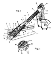
Figur 1 eine schematisierte perspektivische Darstellung einer ersten Ausführungsform der Vorrichtung im Einsatz,Figur 2 eine Detaildarstellung einer Einzelheit gemäß der Kreisangabe Z inFigur 1,Figur 3 eine Seitenansicht der Vorrichtung in einer weiteren Ausführungsform,Figur 4 eine vergrößernde Darstellung der Vorrichtung gemäß Figur 3 im Rostbereich,Figur 5 einen Ausschnitt eines Schnitts durch den Rost senkrecht zu der Achse der Welle der Fördereinrichtung,Figur 6 eine ähnliche Schnittdarstellung mit elastisch ausgebildetem Randbereich der Förderwendel undFigur 7 eine weitere Ausführungsmöglichkeit der elastischen Gestaltung der Förderwendel.
- FIG. 1 shows a schematic perspective illustration of a first embodiment of the device in use,
- FIG. 2 shows a detail of a detail according to the circle Z in FIG. 1,
- FIG. 3 shows a side view of the device in a further embodiment,
- FIG. 4 shows an enlarged view of the device according to FIG. 3 in the grate area,
- FIG. 5 shows a section of a section through the grate perpendicular to the axis of the shaft of the conveying device,
- Figure 6 is a similar sectional view with an elastic edge region of the conveyor spiral and
- Figure 7 shows another embodiment of the elastic design of the conveyor spiral.
In einem in Figur 1 schematisch dargestellten Gerinne 1 ist die Vorrichtung mit ihrer Achse 2 - schrägstehend, also weder horizontal noch vertikal, so angeordnet, daß sie mit einem Teil an Seitenwandungen 3 des Gerinnes 1 anschließt, in welchem sich ein Wasserstand 4 vor der Vorrichtung und ein demgegenüber niederer Wasserstand nach der Vorrichtung befindet, so daß das Gerinne 1 in Richtung eines Pfeils 6 durchströmt wird.In a
Die Vorrichtung weist in ihrem unteren Teil einen Rost 7 auf, der sich mindestens über eine solche Höhe parallel zur Achse 2 erstreckt, daß der unter den Wasserstand 4 eingreifende Teil sich immer im Wasser befindet und auch unterschiedlichen Wasserständen Rechnung getragen ist. Der Rost 7 besteht im wesentlichen aus Roststäben 8, die parallel zur Achse 2 auf der Mantellinie eines Zylinders angeordnet sind, sowie aus Abstützstäben 9, die sich über ein Zylindersegment tangential zu dem Umfang des Zylinders der Roststäbe 8 und damit senkrecht zu der Achse 2 erstrecken. Es versteht sich, daß die Abstützstäbe 9 über die Umfangsfläche des Rosts 7 bis auf die andere Seite durchgehend angeordnet sind, obwohl dies aus Übersichtlichkeitsgründen nicht dargestellt ist.The device has in its lower part a
Die Abstützstäbe 9 befinden sich auf einem größeren Durchmesser als die Roststäbe 8, gesehen von der Achse 2 aus, so daß zwischen den Roststäben 8 parallel zur Achse 2 durchgehende und ununterbrochene Längsschlitze 10 gebildet sind. Der Rost 7 kann an seinem unteren Ende ein Stirnblech 11 aufweisen, welches zusätzlich zu den Abstützstäben 9 die Roststäbe 8 stabilisiert und in ihrer Lage festhält.The
Im Anschluß an den Rost 7 schräg nach oben ist ein Gehäuse 12 einer Schneckenfördereinrichtung 13 als zylindrische Mantelfläche vorgesehen. In dem Gehäuse 12, welches auch einen konischen Absatz 14 aufweisen kann, ist eine Welle 15 angeordnet, die mit einer Förderwendel 16 verbunden ist bzw. diese trägt, die sich über die Gesamtlänge der Vorrichtung erstreckt und auch in den Teil der Vorrichtung hineinragt, in welchem der Rost 7 angeordnet ist. Dort ist gemäß Figur 1 die Welle 15 nicht vorgesehen bzw. angeordnet und die Förderwendel 16 besitzt einen größeren Durchmesser, der dem inneren Durchmesser der Roststäbe 8 angepaßt ist. Das untere Ende der Förderwendel 16 kann in einem Lager 17 im Bereich des Stirnblechs 13 gelagert sein. Am oberen Ende des Gehäuses 12 ist ein weiteres, hier nicht dargestelltes Lager vorgesehen. Dort ist auch ein Motor 18 und ein Getriebe 19 angeordnet, über die die Welle 15 und damit auch die Förderwendel 16 angetrieben wird. Die Förderwendel 16 kann über ihre axiale Länge nicht konstante Steigung aufweisen. wobei die Steigungen bereichsweise unterschiedlich gestaltet sein können, oder, wie dargestellt, am oberen Ende der Förderstrecke eine Kompaktierzone 20 gebildet sein, in deren Bereich die Förderwendel eine geringere Steigung aufweist. In diesem Bereich ist das Gehäuse 12 auch doppelwandig ausgebildet, wobei der innere Wandungsteil Durchbrechungen aufweist, damit beim Kornpaktieren bzw. Zusammenpressen des Rechenguts abgeschiedene Flüssigkeit über ein Rohr 21 zurück in das Gerinne 1 geleitet werden kann, während das kompaktierte Rechengut 22 über eine Schurre 23 in einen Behälter 24 abgeworfen wird.Following the
Wie insbesondere die Detaildarstellung Z gemäß Figur 2 erkennen läßt, besitzen die Roststäbe 8 etwa dreieckigen Querschnitt, in diesem Fall in Form eines gleichschenkligen Dreiecks, wobei die eine Dreiecksseite 25 tangential zum inneren Umfang des Rosts 7 angeordnet ist, so daß die Spitze des Dreiecks von der Achse 2 aus gesehen radial nach außen ragt. Damit werden die durchgehenden Längsschlitze 10 zwischen den Roststäben 8 gebildet, die engste Stellen 26 aufweisen, die infolge der lediglich abgerundeten Kanten des dreieckigen Querschnitts der Roststäbe 8 nahe am inneren Umfang, also im Anschluß an die Dreiecksseiten 25 vorgesehen sind. In diesem Bereich findet die Abscheidung des Rechenguts 22 gleichsam auf der Innenseite des Rosts 7 statt, während das durch den Rost 7 hindurchtretende Wasser gemäß den Pfeilen 27 einen sich überproportional erweiternden Querschnitt 28 im Anschluß an die engsten Stellen 26 vorfindet. Durch diesen überproportional, d. h. sich stärker, als es der Zunahme des Radiusses an dieser. Stelle von der Achse 2 aus entspricht, erweiternden Querschnitt, wird die Strömungsgeschwindigkeit gemäß den Pfeilen 27, die in sehr starkem Maß herabgestellt, so daß die durchströmende Flüssigkeit nicht die Möglichkeit hat, das abgeschiedene Rechengut 22 durch die Längsschlitze 10 saugend hindurchzuziehen. Das Rechengut 22 verbleibt vielmehr in der abgeschiedenen Stellung und wird bei dem Antrieb der Förderwendel 16 von deren äußerem Rand abgenommen, ergriffen und auf der Innenseite des Rosts 7 nach oben hin weggeführt, wobei es dann in den Bereich des Gehäuses 12 und damit der Förderstrecke dieser Schneckenfördereinrichtung 13 gelangt, um schließlich kompaktiert und in den Behälter 24 abgeworfen zu werden. In Figur 2 sind die die Roststäbe 8 abstützenden Abstützstäbe 9 der Übersichtlichkeit halber nicht dargestellt. Selbstverständlich sind diese Abstützstäbe 9 vorhanden, da sie ein wesentliches Element für die Stabilisierung des Rosts 7 bilden, so daß sich selbst bei Auftreten von hartem Rechengut die Roststäbe 8 nicht durchbiegen können, so daß die Spaltweite der Längsschlitze 10 unverändert konstant gehalten wird. Damit bleibt die Abscheidesicherheit auch über die Betriebszeit erhalten und es werden andererseits keine harten Gegenstände, wie Steine u. dgl, zwischen den Roststäben 8 eingeklemmt. Auch die Durchtrittsflächen des Rosts 7 werden auf diese Art und Weise nicht versperrt.As can be seen in particular from the detailed illustration Z according to FIG. 2, the grate bars 8 have an approximately triangular cross-section, in this case in the form of an isosceles triangle, one
Die Ausführungsform der Vorrichtung gemäß den Figuren 3 und 4 ist an sich ähnlich aufgebaut wie die Ausführungsformen der Figuren 1 und 2. Lediglich die Welle 15 ist hier durchgehend vorgesehen, erstreckt sich also auch in dem Bereich des Rosts 7 und trägt hier die Förderwendel 16. Figur 4 läßt deutlich erkennen, daß die Abstützstäbe 9 auf größerem Durchmesser angeordnet sind als die Roststäbe 8, so daß die Anordnung der Abstützstäbe 9 die Längsschlitze 10 zwischen den Roststäben 8 nicht beeinträchtigen und nicht unterbrechen. Aus Figur 4 und auch aus Figur 3 ist erkennbar, daß der Rost 7 von gehäuseartigen Einlaufwandungen 29 umgeben ist, so daß der Rost 7 hierdurch zusätzlich stabilisiert angeordnet ist. Das untere Lager 17 kann bei dieser Ausführungsform auch fehlen. Stattdessen besteht die Möglichkeit, Gleitlagerringe 30 anzuordnen, die oberhalb des Wasserstands 4 bzw. 5 vorgesehen sind, so daß damit sämtliche Lager für die Welle 15 bzw. die Förderwendel 16 außerhalb des Wassers vorgesehen sind. Die Figuren 3 und 4 verdeutlichen auch den gegenseitigen Abstand der Abstützstäbe 9 im Verhältnis zu der Ausbildung und Anordnung der Roststäbe 8.The embodiment of the device according to FIGS. 3 and 4 is constructed in a manner similar to that of the embodiments of FIGS. 1 and 2. Only the
Aus Figur 4 ist auch erkennbar, daß auch die Abstützstäbe 9 einen etwa dreieckigen oder auch trapezförmigen Querschnitt aufweisen können, jedoch-in umgekehrter Richtung angeordnet sind, wie der Querschnitt der Roststäbe 8. Dies wird im übrigen auch aus Figur 5 erkennbar, die einen Ausschnitt zeigt. Es ist dort ein Schnitt etwa senkrecht zur Achse 2 der Vorrichtung dargestellt, so daß die Querschnittsform und Anordnung der Roststäbe 8 und der Abstützstäbe 9 in ihrer gegenseitigen Zuordnung besonders gut erkennbar sind. Ein Querschnitt 31 der Abstützstäbe 9 ist hier der Deutlichkeit halber eingezeichnet. Die beiden Spitzen der dreieckigen Querschnitte sind einander zugekehrt, so daß hier eine verhältnismäßig kleine Berührfläche geschaffen ist, so daß die Roststäbe 8 und die Abstützstäbe 9 vorteilhaft durch eine Schweißverbindung unter Druck miteinander in Verbindung gebracht werden können, wobei eine große Vielzahl von Verbindungsstellen entsteht und andererseits der Durchmesser und die Anordnung der Dreiecksseiten 25 auf ihrem Durchmesser nicht beeinträchtigt wird. Aus dieser Darstellung ist auch gut die engste Stelle 26 und der sich darin anschließende erweiternde Querschnitt 28 zu sehen, jeweils gesehen in Strömungsrichtung 32 der Flüssigkeit, d. h. radial zu der Achse 2 bzw. in Richtung des Pfeils 27.It can also be seen from FIG. 4 that the
In den Figuren 6 und 7 sind zwei Schnittdarstellungen etwa senkrecht zu der Achse 2 der Vorrichtung dargestellt, um zu verdeutlichen, auf welche Art und Weise der Kontakt zwischen der Förderwendel 16 und dem Rost 7 noch weiter verbessert werden kann. Die Förderwendel 16 weist einen äußeren Rand 33 auf, der den Dreiecksseiten 25 der Roststäbe 8 des Rosts 7 zugekehrt ist. In dieser Fläche ist zweckmäßig eine schwalbenschwanzförmige Nut 34 eingearbeitet, in welcher eine Borstenleiste 35 (Figur 6) oder eine Abstreiflippe 37 (Figur 7) eingelassen sind. Die Abstreifleiste 36 ist zweckmäßig als weiches, aber abriebfestes Kunststoffprofil ausgebildet. Durch die Rückstellkraft der Borsten der Borstenleiste 35 bzw. die Elastizität der Abstreiflippe 36 wird gewährleistet, daß beim Umlauf die Förderwendel 16 an jeder Stelle des Umfangs in Kontakt mit den Dreiecksseiten 25 der Roststäbe 8 bleibt und das dort abgelagerte Rechengut verläßlich abstreift, nach oben fördert und auf diese Art und Weise den Rost 7 kontinuierlich reinigt.FIGS. 6 and 7 show two sectional representations approximately perpendicular to the
- 1 = Gerinnet1 = clotted
- 2 = Achse2 = axis
- 3 = Seitenwandung3 = side wall
- 4 = Wasserstand4 = water level
- 5 = Wasserstand5 = water level
- 6 = Pfeil6 = arrow
- 7 = Rost7 = rust
- 8 = Roststäbe8 = grate bars
- 9 = Abstützstäbe9 = support rods
- 10 = Längsschlitze10 = longitudinal slots
- 11 = Stirnfläche11 = face
- 12 = Gehäuse12 = housing
- 13 = Schneckenfördereinrichtung13 = screw conveyor
- 14 = Absatz14 = paragraph
- 15 = Welle15 = wave
- 16 = Förderwendel16 = conveyor helix
- 17 = Lager17 = warehouse
- 18 = Motor18 = motor
- 19 = Getriebe19 = gear
- 20 = Kompaktierzone20 = compacting zone
- 21 = Rohr21 = pipe
- 22 = Rechengut22 = screenings
- 23 = Schürze23 = apron
- 24 = Behälter24 = container
- 25 = Dreiecksseite25 = triangle side
- 26 = engste Stelle26 = narrowest point
- 27 = Pfeil27 = arrow
- 28 = Querschnitt28 = cross section
- 29 = Einlaufwandung29 = inlet wall
- 30 = Gleitlagerring30 = plain bearing ring
- 31 = Querschnitt31 = cross section
- 32 = Strömungsrichtung32 = flow direction
- 33 = äußerer Rand33 = outer edge
- 34 = Nut34 = groove
- 35 = Borstenleiste35 = bristle strip
- 36 = Abstreiflippe36 = wiper lip
Claims (12)
Priority Applications (1)
| Application Number | Priority Date | Filing Date | Title |
|---|---|---|---|
| AT87117680T ATE79144T1 (en) | 1987-05-16 | 1987-11-30 | DEVICE FOR REMOVAL OF SCREENS AND/OR SCREENS FROM LIQUID FLOWING IN A CHANNEL. |
Applications Claiming Priority (2)
| Application Number | Priority Date | Filing Date | Title |
|---|---|---|---|
| DE3716434A DE3716434C1 (en) | 1987-05-16 | 1987-05-16 | Device for removing screenings and / or screenings from liquid flowing in a channel |
| DE3716434 | 1987-05-16 |
Publications (3)
| Publication Number | Publication Date |
|---|---|
| EP0293515A2 true EP0293515A2 (en) | 1988-12-07 |
| EP0293515A3 EP0293515A3 (en) | 1989-04-26 |
| EP0293515B1 EP0293515B1 (en) | 1992-08-05 |
Family
ID=6327701
Family Applications (1)
| Application Number | Title | Priority Date | Filing Date |
|---|---|---|---|
| EP87117680A Expired - Lifetime EP0293515B1 (en) | 1987-05-16 | 1987-11-30 | Device for removing solids from liquid flowing in a sewer |
Country Status (12)
| Country | Link |
|---|---|
| US (1) | US4859322A (en) |
| EP (1) | EP0293515B1 (en) |
| JP (1) | JPS63293213A (en) |
| KR (1) | KR960008706B1 (en) |
| AT (1) | ATE79144T1 (en) |
| BR (1) | BR8800872A (en) |
| CA (1) | CA1330957C (en) |
| DE (1) | DE3716434C1 (en) |
| DK (1) | DK44488A (en) |
| ES (1) | ES2033780T3 (en) |
| GR (1) | GR3005501T3 (en) |
| PT (1) | PT86658B (en) |
Cited By (6)
| Publication number | Priority date | Publication date | Assignee | Title |
|---|---|---|---|---|
| EP0389789A2 (en) * | 1989-03-31 | 1990-10-03 | Hans-Georg Huber | Device for removing solids from liquids flowing in a gutter |
| WO1991013672A2 (en) * | 1990-03-06 | 1991-09-19 | Abel Guenther | Apparatus for separating liquids and solids |
| EP0554580A1 (en) * | 1992-02-04 | 1993-08-11 | Fuchs Maschinenbau | Apparatus for separating solids from a flowing liquid, method of operation and use of the apparatus |
| EP0565898A1 (en) * | 1992-04-07 | 1993-10-20 | Hans Georg Huber | Device for separating solid matter from a liquid with a cylindrical liquid permeable separating surface and for removing solid matter |
| CN101979784A (en) * | 2010-04-27 | 2011-02-23 | 孙光斌 | Spiral centrifugal boring dredger |
| AT515053A1 (en) * | 2013-10-28 | 2015-05-15 | Ernst Ing Kurri | Arrangement for filling a silo |
Families Citing this family (59)
| Publication number | Priority date | Publication date | Assignee | Title |
|---|---|---|---|---|
| DE3915528C1 (en) * | 1989-05-12 | 1990-12-13 | Noggerath & Co, 3061 Ahnsen, De | Screw conveyor with material moisture reduction - has spiral brush in grate region, matching pitch of conveyor screw |
| DE3920196A1 (en) * | 1989-06-21 | 1991-01-10 | Huber Hans Georg Dipl Ing | Trash-removal equipment from gutter - has inclined cylindrical grille of smaller free cross=section at bottom end |
| US5006236A (en) * | 1989-09-25 | 1991-04-09 | Hallco Fabricators, Inc. | Contaminant entrained flow separating apparatus |
| US5110461A (en) * | 1990-09-05 | 1992-05-05 | Abel Guenther | Apparatus for separating liquids and solids |
| FI87186C (en) * | 1990-11-19 | 1992-12-10 | Ekotuotanto Ab Oy | Screw Grating |
| DE4120846A1 (en) * | 1991-06-25 | 1993-01-14 | Ibo W Grimmel Abwassertechnik | Equipment for pretreatment of strongly contaminated water - involves worm pump delivering water from input to a higher located duct and having extension in which the worm works |
| DE4143376C2 (en) * | 1991-06-28 | 1994-12-15 | Hans Georg Huber | Compact system for separating and removing screenings and sand from feed channels |
| DE4138825C2 (en) * | 1991-11-26 | 1994-02-10 | Huber Hans Gmbh | Device for removing screenings and / or screenings from liquid flowing in a channel |
| JPH0710440B2 (en) * | 1992-02-21 | 1995-02-08 | アムコン株式会社 | Solid-liquid separation device |
| DE4211659C2 (en) * | 1992-04-07 | 1996-03-28 | Hans Georg Huber | Device for removing material to be separated from a liquid with a cylindrical jacket-shaped, liquid-permeable separation surface |
| DE4235903C2 (en) * | 1992-10-23 | 1995-05-24 | Hans Georg Huber | Device for removing material to be separated from a liquid flowing in a channel |
| DE4237123C2 (en) * | 1992-11-03 | 1995-02-16 | Hans Georg Huber | Device for cleaning large amounts of water from screenings |
| DE4320678C2 (en) * | 1993-06-22 | 1996-04-11 | Branko Dipl Ing Klasnic | Device for removing screenings from a feed channel through which a contaminated liquid flows, in particular from sewage treatment plants |
| DE4328476C2 (en) * | 1993-08-24 | 1997-10-30 | Rudolf Bischof Gmbh Tech Hande | Device for discharging solid components from a fluid |
| DE4407525C1 (en) * | 1994-03-07 | 1995-11-02 | Spirac Engineering Ab | Device for separating solids from a liquid |
| DE4419612A1 (en) * | 1994-06-03 | 1995-12-07 | Noggerath Holding Gmbh Co Kg | Spiral conveyor |
| DE9410097U1 (en) * | 1994-06-22 | 1994-08-11 | Basika Entwaesserungen Gmbh | Grease trap |
| DE19508894A1 (en) * | 1995-03-11 | 1996-10-10 | Egner Andrea | Equipment for are oval of solids from liquid-solid mass |
| DE19520992C2 (en) * | 1995-06-08 | 1999-08-12 | Premark Feg L L C N D Ges D St | Device and method for removing waste from water |
| DE29511462U1 (en) * | 1995-07-15 | 1995-09-28 | Huber Hans Gmbh Maschinen Und | Device for removing material to be separated from a liquid flowing in a channel |
| US5540844A (en) * | 1995-07-21 | 1996-07-30 | Meylor; Donald M. | Dewatering system |
| AUPN817896A0 (en) * | 1996-02-21 | 1996-03-14 | Nicholas, Douglas Ian | Stormwater sediment and litter trap |
| US5770094A (en) * | 1996-10-01 | 1998-06-23 | Johnson Machine Works, Inc. | Screw conveyor screening apparatus for removing solids from wastewater |
| FR2754812B1 (en) * | 1996-10-17 | 1998-12-04 | Poitevine De Filtration Soc | APPARATUS FOR THICKENING LIQUID / SOLID SEWAGE TREATMENT AND SLUDGE STATION |
| DE19744524C2 (en) * | 1997-10-09 | 2003-11-20 | Hans Huber Ag Masch & Anlagenb | Screening device for waste water arriving in an inlet pipe |
| US5980740A (en) * | 1998-01-06 | 1999-11-09 | Civitas Erosion Services, Inc. | Storm drain collection box filtration system |
| NO310454B1 (en) * | 1999-04-21 | 2001-07-09 | Harry Simonsen | Device for separating contamination from washing water from a washing device for net bags to cages |
| DE29920552U1 (en) | 1999-11-23 | 2000-02-17 | Klasnic Branko | Device for removing screenings from a channel with a flow |
| DE10030784B4 (en) * | 2000-06-29 | 2006-04-20 | Kilia-Fleischerei- Und Spezial-Maschinen Fabrik Gmbh | Device for dewatering solids separated from fluids |
| EP1313922B1 (en) * | 2000-08-29 | 2007-01-24 | Hydro International Plc | Screen assembly for combined sewer overflow weir |
| DE10100534B4 (en) * | 2001-01-05 | 2004-05-19 | Stefan Barth | End of orbit, oscillating, rising incline |
| NZ513379A (en) * | 2001-08-07 | 2004-03-26 | Power Glides Screens Ltd | Suspension screen raking system (NO.2) |
| US7350964B2 (en) * | 2003-03-04 | 2008-04-01 | Lothar Wellenbrock | Device for circulating grain products |
| DE10316173B4 (en) * | 2003-04-04 | 2006-03-16 | Hans Huber Ag Maschinen- Und Anlagenbau | Device for removing fine screenings from a liquid |
| ITMO20060207A1 (en) * | 2006-06-27 | 2007-12-28 | Wam Spa | AUGER TO BE USED FOR CONVEYORS, COMPACTORS AND THE LIKE. |
| JP4753911B2 (en) * | 2007-04-27 | 2011-08-24 | 中国電力株式会社 | Dust remover |
| JP4524351B2 (en) | 2008-02-01 | 2010-08-18 | 三菱重工業株式会社 | Organic raw material production system and method using biomass raw material |
| JP4427583B2 (en) | 2008-02-01 | 2010-03-10 | 三菱重工業株式会社 | Biothermal decomposition apparatus and method for biomass, and organic raw material production system using biomass raw material |
| KR100941923B1 (en) * | 2008-02-13 | 2010-02-11 | 주식회사 한성환경기연 | Brush setting structure of screw conveyor |
| DE102008046928A1 (en) * | 2008-09-12 | 2010-03-18 | Georg Klaß sen. | Screw filter press |
| GB2474688B (en) * | 2009-10-23 | 2014-05-07 | M & N Electrical And Mechanical Services Ltd | Separating apparatus |
| CA2741598C (en) | 2010-03-10 | 2013-04-30 | Mitsubishi Heavy Industries, Ltd. | Biomass hydrothermal decomposition apparatus, temperature control method thereof, and organic raw material production system using biomass material |
| CA2741602C (en) | 2010-03-10 | 2013-04-30 | Mitsubishi Heavy Industries, Ltd. | Biomass hydrothermal decomposition apparatus, temperature control method thereof, and organic raw material production system using biomass material |
| JP5854586B2 (en) | 2010-07-06 | 2016-02-09 | 三菱重工メカトロシステムズ株式会社 | Fermentation system and method using sugar solution |
| CA2750754C (en) | 2010-07-09 | 2015-06-30 | Mitsubishi Heavy Industries, Ltd. | Biomass hydrothermal decomposition system and saccharide-solution production method using biomass material |
| JP4764527B1 (en) | 2010-07-09 | 2011-09-07 | 三菱重工業株式会社 | Biomass processing system and sugar liquid production method using biomass raw material |
| DE102010038417A1 (en) | 2010-07-26 | 2012-01-26 | Huber Se | Apparatus and method for removing screenings from a liquid |
| BRPI1005516B1 (en) * | 2010-09-03 | 2019-12-03 | Mitsubishi Heavy Ind Ltd | biomass decomposition apparatus |
| ITBO20100093U1 (en) * | 2010-09-15 | 2012-03-16 | Cms Spa | WASTE COMPACTOR, SIMPLIFIED CONSTRUCTION AND SMALL DIMENSIONS, PARTICULARLY FOR BARS, HOT TABLES OR OTHER SMALL CATERING EXERCISES. |
| WO2012095976A1 (en) | 2011-01-13 | 2012-07-19 | 三菱重工メカトロシステムズ株式会社 | Device for producing sugar solution, fermentation system, method for producing sugar solution and fermentation method |
| KR101133112B1 (en) * | 2011-07-29 | 2012-04-06 | 제천시 | Device of dehydration for sludge, oil, adulteration and sand |
| CA2868572C (en) | 2012-03-29 | 2015-04-28 | Mitsubishi Heavy Industries Mechatronics Systems, Ltd. | Biomass processing system, saccharide solution production method using biomass feedstock, alcohol production method |
| CN103568353B (en) * | 2012-07-20 | 2015-09-30 | 北京天高智机技术开发公司 | A kind of changing food waste slurry slag separator |
| JP6138029B2 (en) * | 2013-11-18 | 2017-05-31 | 日立造船株式会社 | Sediment discharge facility for dam reservoir |
| WO2019150168A1 (en) * | 2018-02-01 | 2019-08-08 | Universidad Tecnológica De Panamá (Utp) | Apparatus for collecting solid waste from a water course |
| US10968617B2 (en) * | 2019-06-04 | 2021-04-06 | Terry Duperon | Lift station maintenance device |
| DE102019007315B3 (en) * | 2019-10-21 | 2020-11-05 | Stefan Barth | Combination rotation lever with screw conveyor for small hydropower plants |
| CN112516710A (en) * | 2020-12-02 | 2021-03-19 | 李扬 | Environment-friendly industrial waste gas purification device |
| CN113207834B (en) * | 2021-06-15 | 2022-08-19 | 长江师范学院 | Automatic insect trapping device and operation method |
Citations (9)
| Publication number | Priority date | Publication date | Assignee | Title |
|---|---|---|---|---|
| FR352616A (en) * | 1905-03-22 | 1905-08-16 | Charles Constant Leclaire | Filter for automatic and continuous formation and evacuation of solid deposits |
| US3379312A (en) * | 1965-03-16 | 1968-04-23 | North American Rockwell | Fluid strainers |
| FR2107102A5 (en) * | 1970-09-04 | 1972-05-05 | Doucet Charles | |
| DE2142540A1 (en) * | 1971-08-25 | 1973-03-01 | Benno Reiche | RAKE CLEANER |
| FR2238887A1 (en) * | 1973-07-25 | 1975-02-21 | Muanyagipari Kutato Intezet | Suspensions transferred between closed systems - without loss of pressure or wastage using piston and valved cylinder |
| EP0040425A2 (en) * | 1980-05-20 | 1981-11-25 | Günther Abel | Device for removing floating materials and debris from a gully, especially from purification plants |
| EP0067912A1 (en) * | 1981-06-19 | 1982-12-29 | The Black Clawson Company | Paper making stock screen and a system for treating paper making stock |
| DE3434301A1 (en) * | 1984-09-19 | 1986-03-27 | Willi 4973 Vlotho Cordes | Installation for treating sewage |
| EP0182688A1 (en) * | 1984-11-12 | 1986-05-28 | E. + M. Lamort Société Anonyme dite: | Purification strainers and method for their production |
Family Cites Families (14)
| Publication number | Priority date | Publication date | Assignee | Title |
|---|---|---|---|---|
| BE524160A (en) * | ||||
| US689440A (en) * | 1901-02-18 | 1901-12-24 | Gustave R Tuska | Pressing apparatus. |
| US1096199A (en) * | 1913-02-27 | 1914-05-12 | Logan Iron Works | Screw-press. |
| US2491912A (en) * | 1947-01-30 | 1949-12-20 | Marcus A Walker | Apparatus for separating materials |
| US2929504A (en) * | 1958-05-19 | 1960-03-22 | Chain Belt Co | Waste-flow screening apparatus |
| US3688687A (en) * | 1970-11-16 | 1972-09-05 | Wascon Systems Inc | Press |
| US3695173A (en) * | 1972-01-28 | 1972-10-03 | Clyde Harold Cox | Sludge dewatering |
| DD105189A1 (en) * | 1973-07-27 | 1974-04-12 | ||
| SU1134375A1 (en) * | 1981-07-27 | 1985-01-15 | Предприятие П/Я Р-6956 | Press screw for separating solid from liquid |
| JPS58187644A (en) * | 1982-04-27 | 1983-11-01 | Anritsu Corp | Releasable supporting device of ball screw |
| US4424129A (en) * | 1982-06-28 | 1984-01-03 | Bunger Richard E | Dewatering apparatus for waste recovery systems |
| DD213353A1 (en) * | 1983-02-02 | 1984-09-12 | Rationalisierungsmittelbau D P | DEVICE FOR CONTINUOUS SEPARATION OF A SOLIDS-FLUID MIXTURE |
| DE3420157C1 (en) * | 1984-05-30 | 1986-01-23 | Hans Huber GmbH, 8434 Berching | Device for removing screenings and / or screenings from liquid flowing in a channel |
| JPS61169521U (en) * | 1985-04-10 | 1986-10-21 |
-
1987
- 1987-05-16 DE DE3716434A patent/DE3716434C1/en not_active Expired
- 1987-11-30 EP EP87117680A patent/EP0293515B1/en not_active Expired - Lifetime
- 1987-11-30 AT AT87117680T patent/ATE79144T1/en not_active IP Right Cessation
- 1987-11-30 ES ES198787117680T patent/ES2033780T3/en not_active Expired - Lifetime
- 1987-12-22 US US07/136,835 patent/US4859322A/en not_active Expired - Fee Related
-
1988
- 1988-01-18 CA CA000556738A patent/CA1330957C/en not_active Expired - Fee Related
- 1988-01-28 PT PT86658A patent/PT86658B/en not_active IP Right Cessation
- 1988-01-29 DK DK044488A patent/DK44488A/en not_active Application Discontinuation
- 1988-01-29 JP JP63017474A patent/JPS63293213A/en active Pending
- 1988-02-15 KR KR1019880001563A patent/KR960008706B1/en active IP Right Grant
- 1988-02-29 BR BR8800872A patent/BR8800872A/en unknown
-
1992
- 1992-08-20 GR GR920401843T patent/GR3005501T3/el unknown
Patent Citations (9)
| Publication number | Priority date | Publication date | Assignee | Title |
|---|---|---|---|---|
| FR352616A (en) * | 1905-03-22 | 1905-08-16 | Charles Constant Leclaire | Filter for automatic and continuous formation and evacuation of solid deposits |
| US3379312A (en) * | 1965-03-16 | 1968-04-23 | North American Rockwell | Fluid strainers |
| FR2107102A5 (en) * | 1970-09-04 | 1972-05-05 | Doucet Charles | |
| DE2142540A1 (en) * | 1971-08-25 | 1973-03-01 | Benno Reiche | RAKE CLEANER |
| FR2238887A1 (en) * | 1973-07-25 | 1975-02-21 | Muanyagipari Kutato Intezet | Suspensions transferred between closed systems - without loss of pressure or wastage using piston and valved cylinder |
| EP0040425A2 (en) * | 1980-05-20 | 1981-11-25 | Günther Abel | Device for removing floating materials and debris from a gully, especially from purification plants |
| EP0067912A1 (en) * | 1981-06-19 | 1982-12-29 | The Black Clawson Company | Paper making stock screen and a system for treating paper making stock |
| DE3434301A1 (en) * | 1984-09-19 | 1986-03-27 | Willi 4973 Vlotho Cordes | Installation for treating sewage |
| EP0182688A1 (en) * | 1984-11-12 | 1986-05-28 | E. + M. Lamort Société Anonyme dite: | Purification strainers and method for their production |
Cited By (9)
| Publication number | Priority date | Publication date | Assignee | Title |
|---|---|---|---|---|
| EP0389789A2 (en) * | 1989-03-31 | 1990-10-03 | Hans-Georg Huber | Device for removing solids from liquids flowing in a gutter |
| EP0389789A3 (en) * | 1989-03-31 | 1990-11-14 | Hans-Georg Huber | Device for removing solids from liquids flowing in a gutter |
| WO1991013672A2 (en) * | 1990-03-06 | 1991-09-19 | Abel Guenther | Apparatus for separating liquids and solids |
| WO1991013672A3 (en) * | 1990-03-06 | 1991-12-12 | Abel Guenther | Apparatus for separating liquids and solids |
| EP0554580A1 (en) * | 1992-02-04 | 1993-08-11 | Fuchs Maschinenbau | Apparatus for separating solids from a flowing liquid, method of operation and use of the apparatus |
| EP0565898A1 (en) * | 1992-04-07 | 1993-10-20 | Hans Georg Huber | Device for separating solid matter from a liquid with a cylindrical liquid permeable separating surface and for removing solid matter |
| CN101979784A (en) * | 2010-04-27 | 2011-02-23 | 孙光斌 | Spiral centrifugal boring dredger |
| AT515053A1 (en) * | 2013-10-28 | 2015-05-15 | Ernst Ing Kurri | Arrangement for filling a silo |
| AT515053B1 (en) * | 2013-10-28 | 2017-01-15 | Ing Kurri Ernst | Arrangement for filling a silo |
Also Published As
| Publication number | Publication date |
|---|---|
| ATE79144T1 (en) | 1992-08-15 |
| BR8800872A (en) | 1988-11-29 |
| EP0293515B1 (en) | 1992-08-05 |
| JPS63293213A (en) | 1988-11-30 |
| CA1330957C (en) | 1994-07-26 |
| US4859322A (en) | 1989-08-22 |
| DE3716434C1 (en) | 1988-12-08 |
| EP0293515A3 (en) | 1989-04-26 |
| DK44488A (en) | 1988-11-17 |
| DK44488D0 (en) | 1988-01-29 |
| KR880014205A (en) | 1988-12-23 |
| GR3005501T3 (en) | 1993-06-07 |
| PT86658A (en) | 1989-05-31 |
| KR960008706B1 (en) | 1996-06-29 |
| ES2033780T3 (en) | 1993-04-01 |
| PT86658B (en) | 1993-09-30 |
Similar Documents
| Publication | Publication Date | Title |
|---|---|---|
| EP0293515B1 (en) | Device for removing solids from liquid flowing in a sewer | |
| EP0389789B1 (en) | Device for removing solids from liquids flowing in a gutter | |
| EP1519823B1 (en) | Device for the continuous filtration of material blends | |
| DE4000248C2 (en) | ||
| DE2314652C2 (en) | Device for cutting short lengths of sections of mineral fibers, in particular glass thread | |
| EP0259547A1 (en) | Device for removing debris from a flowing sewage liquid | |
| DE1761930B2 (en) | DEVICE FOR SIGHTING FIBER FLUSHING | |
| EP1382554B1 (en) | Pneumatic or hydraulic conveying installation for transporting bulk materials | |
| DE19524276C2 (en) | Device for removing material to be separated from liquid flowing in a channel | |
| DE2947294A1 (en) | SPINNING UNIT OF AN OPEN-END SPINNING MACHINE | |
| CH677500A5 (en) | ||
| EP1215335A1 (en) | Pressure screen for cleaning paper pulp containing impurities | |
| EP0567726B1 (en) | Screening device | |
| DE2447360A1 (en) | DEVICE FOR REMOVING FOREIGN BODIES FROM SUGAR BEET OR DGL. | |
| EP0303755B1 (en) | Apparatus for granulating chicken excrements or similar materials | |
| DE4138825C2 (en) | Device for removing screenings and / or screenings from liquid flowing in a channel | |
| DE4328476C2 (en) | Device for discharging solid components from a fluid | |
| EP0623712A2 (en) | Device for removing separable matter from a liquid | |
| DE4213847A1 (en) | Sewage cleaning device for sewage treatment plant - has driven conveyor worm, extending through collection basket and part of inclined conveyor channel | |
| DE2757746A1 (en) | DEVICE FOR PROCESSING A SUSPENSION | |
| EP0336223A2 (en) | Clothing for a cleaning or opening roller | |
| EP0594167A1 (en) | Device for removing separable matter from a liquid flowing in a gutter | |
| DE19625726C1 (en) | Wire unit has sorting gaps for fibre suspension | |
| DE154146C (en) | ||
| DE3615411C2 (en) |
Legal Events
| Date | Code | Title | Description |
|---|---|---|---|
| PUAI | Public reference made under article 153(3) epc to a published international application that has entered the european phase |
Free format text: ORIGINAL CODE: 0009012 |
|
| AK | Designated contracting states |
Kind code of ref document: A2 Designated state(s): AT BE CH ES FR GB GR IT LI LU NL SE |
|
| PUAL | Search report despatched |
Free format text: ORIGINAL CODE: 0009013 |
|
| AK | Designated contracting states |
Kind code of ref document: A3 Designated state(s): AT BE CH ES FR GB GR IT LI LU NL SE |
|
| 17P | Request for examination filed |
Effective date: 19891005 |
|
| 17Q | First examination report despatched |
Effective date: 19901029 |
|
| ITF | It: translation for a ep patent filed |
Owner name: DE DOMINICIS & MAYER S.R.L. |
|
| GRAA | (expected) grant |
Free format text: ORIGINAL CODE: 0009210 |
|
| AK | Designated contracting states |
Kind code of ref document: B1 Designated state(s): AT BE CH ES FR GB GR IT LI LU NL SE |
|
| REF | Corresponds to: |
Ref document number: 79144 Country of ref document: AT Date of ref document: 19920815 Kind code of ref document: T |
|
| GBT | Gb: translation of ep patent filed (gb section 77(6)(a)/1977) | ||
| ET | Fr: translation filed | ||
| REG | Reference to a national code |
Ref country code: GR Ref legal event code: FG4A Free format text: 3005501 |
|
| REG | Reference to a national code |
Ref country code: ES Ref legal event code: FG2A Ref document number: 2033780 Country of ref document: ES Kind code of ref document: T3 |
|
| PLBE | No opposition filed within time limit |
Free format text: ORIGINAL CODE: 0009261 |
|
| STAA | Information on the status of an ep patent application or granted ep patent |
Free format text: STATUS: NO OPPOSITION FILED WITHIN TIME LIMIT |
|
| 26N | No opposition filed | ||
| EPTA | Lu: last paid annual fee | ||
| PGFP | Annual fee paid to national office [announced via postgrant information from national office to epo] |
Ref country code: SE Payment date: 19941014 Year of fee payment: 8 |
|
| PGFP | Annual fee paid to national office [announced via postgrant information from national office to epo] |
Ref country code: FR Payment date: 19941028 Year of fee payment: 8 |
|
| PGFP | Annual fee paid to national office [announced via postgrant information from national office to epo] |
Ref country code: GB Payment date: 19941122 Year of fee payment: 8 |
|
| PGFP | Annual fee paid to national office [announced via postgrant information from national office to epo] |
Ref country code: ES Payment date: 19941124 Year of fee payment: 8 |
|
| PGFP | Annual fee paid to national office [announced via postgrant information from national office to epo] |
Ref country code: AT Payment date: 19941125 Year of fee payment: 8 |
|
| PGFP | Annual fee paid to national office [announced via postgrant information from national office to epo] |
Ref country code: GR Payment date: 19941129 Year of fee payment: 8 |
|
| PGFP | Annual fee paid to national office [announced via postgrant information from national office to epo] |
Ref country code: NL Payment date: 19941130 Year of fee payment: 8 |
|
| PGFP | Annual fee paid to national office [announced via postgrant information from national office to epo] |
Ref country code: LU Payment date: 19941201 Year of fee payment: 8 Ref country code: CH Payment date: 19941201 Year of fee payment: 8 |
|
| PGFP | Annual fee paid to national office [announced via postgrant information from national office to epo] |
Ref country code: BE Payment date: 19941206 Year of fee payment: 8 |
|
| EAL | Se: european patent in force in sweden |
Ref document number: 87117680.6 |
|
| PG25 | Lapsed in a contracting state [announced via postgrant information from national office to epo] |
Ref country code: LU Free format text: LAPSE BECAUSE OF NON-PAYMENT OF DUE FEES Effective date: 19951130 Ref country code: LI Effective date: 19951130 Ref country code: GB Effective date: 19951130 Ref country code: CH Effective date: 19951130 Ref country code: BE Effective date: 19951130 Ref country code: AT Effective date: 19951130 |
|
| PG25 | Lapsed in a contracting state [announced via postgrant information from national office to epo] |
Ref country code: SE Effective date: 19951201 Ref country code: ES Free format text: LAPSE BECAUSE OF EXPIRATION OF PROTECTION Effective date: 19951201 |
|
| BERE | Be: lapsed |
Owner name: HUBER HANS-GEORG Effective date: 19951130 |
|
| PG25 | Lapsed in a contracting state [announced via postgrant information from national office to epo] |
Ref country code: GR Free format text: THE PATENT HAS BEEN ANNULLED BY A DECISION OF A NATIONAL AUTHORITY Effective date: 19960531 |
|
| PG25 | Lapsed in a contracting state [announced via postgrant information from national office to epo] |
Ref country code: NL Effective date: 19960601 |
|
| REG | Reference to a national code |
Ref country code: CH Ref legal event code: PL |
|
| GBPC | Gb: european patent ceased through non-payment of renewal fee |
Effective date: 19951130 |
|
| PG25 | Lapsed in a contracting state [announced via postgrant information from national office to epo] |
Ref country code: FR Effective date: 19960731 |
|
| REG | Reference to a national code |
Ref country code: GR Ref legal event code: MM2A Free format text: 3005501 |
|
| NLV4 | Nl: lapsed or anulled due to non-payment of the annual fee |
Effective date: 19960601 |
|
| REG | Reference to a national code |
Ref country code: FR Ref legal event code: ST |
|
| REG | Reference to a national code |
Ref country code: ES Ref legal event code: FD2A Effective date: 20010201 |
|
| PG25 | Lapsed in a contracting state [announced via postgrant information from national office to epo] |
Ref country code: IT Free format text: LAPSE BECAUSE OF NON-PAYMENT OF DUE FEES;WARNING: LAPSES OF ITALIAN PATENTS WITH EFFECTIVE DATE BEFORE 2007 MAY HAVE OCCURRED AT ANY TIME BEFORE 2007. THE CORRECT EFFECTIVE DATE MAY BE DIFFERENT FROM THE ONE RECORDED. Effective date: 20051130 |