EP0293227A2 - Stand mechanism for a medical optical equipment - Google Patents
Stand mechanism for a medical optical equipmentInfo
- Publication number
- EP0293227A2 EP0293227A2 EP88304835A EP88304835A EP0293227A2 EP 0293227 A2 EP0293227 A2 EP 0293227A2 EP 88304835 A EP88304835 A EP 88304835A EP 88304835 A EP88304835 A EP 88304835A EP 0293227 A2 EP0293227 A2 EP 0293227A2
- Authority
- EP
- European Patent Office
- Prior art keywords
- optical equipment
- parallel linkage
- counterweight
- center shaft
- supporting
- Prior art date
- Legal status (The legal status is an assumption and is not a legal conclusion. Google has not performed a legal analysis and makes no representation as to the accuracy of the status listed.)
- Withdrawn
Links
Images


Classifications
-
- G—PHYSICS
- G02—OPTICS
- G02B—OPTICAL ELEMENTS, SYSTEMS OR APPARATUS
- G02B7/00—Mountings, adjusting means, or light-tight connections, for optical elements
-
- A—HUMAN NECESSITIES
- A61—MEDICAL OR VETERINARY SCIENCE; HYGIENE
- A61B—DIAGNOSIS; SURGERY; IDENTIFICATION
- A61B6/00—Apparatus or devices for radiation diagnosis; Apparatus or devices for radiation diagnosis combined with radiation therapy equipment
- A61B6/44—Constructional features of apparatus for radiation diagnosis
- A61B6/4429—Constructional features of apparatus for radiation diagnosis related to the mounting of source units and detector units
- A61B6/447—Constructional features of apparatus for radiation diagnosis related to the mounting of source units and detector units the source unit or the detector unit being mounted to counterpoise or springs
-
- A—HUMAN NECESSITIES
- A61—MEDICAL OR VETERINARY SCIENCE; HYGIENE
- A61B—DIAGNOSIS; SURGERY; IDENTIFICATION
- A61B3/00—Apparatus for testing the eyes; Instruments for examining the eyes
- A61B3/18—Arrangement of plural eye-testing or -examining apparatus
-
- A—HUMAN NECESSITIES
- A61—MEDICAL OR VETERINARY SCIENCE; HYGIENE
- A61B—DIAGNOSIS; SURGERY; IDENTIFICATION
- A61B90/00—Instruments, implements or accessories specially adapted for surgery or diagnosis and not covered by any of the groups A61B1/00 - A61B50/00, e.g. for luxation treatment or for protecting wound edges
- A61B90/50—Supports for surgical instruments, e.g. articulated arms
-
- F—MECHANICAL ENGINEERING; LIGHTING; HEATING; WEAPONS; BLASTING
- F16—ENGINEERING ELEMENTS AND UNITS; GENERAL MEASURES FOR PRODUCING AND MAINTAINING EFFECTIVE FUNCTIONING OF MACHINES OR INSTALLATIONS; THERMAL INSULATION IN GENERAL
- F16M—FRAMES, CASINGS OR BEDS OF ENGINES, MACHINES OR APPARATUS, NOT SPECIFIC TO ENGINES, MACHINES OR APPARATUS PROVIDED FOR ELSEWHERE; STANDS; SUPPORTS
- F16M11/00—Stands or trestles as supports for apparatus or articles placed thereon ; Stands for scientific apparatus such as gravitational force meters
- F16M11/02—Heads
- F16M11/04—Means for attachment of apparatus; Means allowing adjustment of the apparatus relatively to the stand
- F16M11/06—Means for attachment of apparatus; Means allowing adjustment of the apparatus relatively to the stand allowing pivoting
- F16M11/10—Means for attachment of apparatus; Means allowing adjustment of the apparatus relatively to the stand allowing pivoting around a horizontal axis
-
- F—MECHANICAL ENGINEERING; LIGHTING; HEATING; WEAPONS; BLASTING
- F16—ENGINEERING ELEMENTS AND UNITS; GENERAL MEASURES FOR PRODUCING AND MAINTAINING EFFECTIVE FUNCTIONING OF MACHINES OR INSTALLATIONS; THERMAL INSULATION IN GENERAL
- F16M—FRAMES, CASINGS OR BEDS OF ENGINES, MACHINES OR APPARATUS, NOT SPECIFIC TO ENGINES, MACHINES OR APPARATUS PROVIDED FOR ELSEWHERE; STANDS; SUPPORTS
- F16M11/00—Stands or trestles as supports for apparatus or articles placed thereon ; Stands for scientific apparatus such as gravitational force meters
- F16M11/02—Heads
- F16M11/18—Heads with mechanism for moving the apparatus relatively to the stand
-
- F—MECHANICAL ENGINEERING; LIGHTING; HEATING; WEAPONS; BLASTING
- F16—ENGINEERING ELEMENTS AND UNITS; GENERAL MEASURES FOR PRODUCING AND MAINTAINING EFFECTIVE FUNCTIONING OF MACHINES OR INSTALLATIONS; THERMAL INSULATION IN GENERAL
- F16M—FRAMES, CASINGS OR BEDS OF ENGINES, MACHINES OR APPARATUS, NOT SPECIFIC TO ENGINES, MACHINES OR APPARATUS PROVIDED FOR ELSEWHERE; STANDS; SUPPORTS
- F16M11/00—Stands or trestles as supports for apparatus or articles placed thereon ; Stands for scientific apparatus such as gravitational force meters
- F16M11/20—Undercarriages with or without wheels
- F16M11/2007—Undercarriages with or without wheels comprising means allowing pivoting adjustment
- F16M11/2035—Undercarriages with or without wheels comprising means allowing pivoting adjustment in more than one direction
-
- F—MECHANICAL ENGINEERING; LIGHTING; HEATING; WEAPONS; BLASTING
- F16—ENGINEERING ELEMENTS AND UNITS; GENERAL MEASURES FOR PRODUCING AND MAINTAINING EFFECTIVE FUNCTIONING OF MACHINES OR INSTALLATIONS; THERMAL INSULATION IN GENERAL
- F16M—FRAMES, CASINGS OR BEDS OF ENGINES, MACHINES OR APPARATUS, NOT SPECIFIC TO ENGINES, MACHINES OR APPARATUS PROVIDED FOR ELSEWHERE; STANDS; SUPPORTS
- F16M11/00—Stands or trestles as supports for apparatus or articles placed thereon ; Stands for scientific apparatus such as gravitational force meters
- F16M11/20—Undercarriages with or without wheels
- F16M11/2092—Undercarriages with or without wheels comprising means allowing depth adjustment, i.e. forward-backward translation of the head relatively to the undercarriage
-
- F—MECHANICAL ENGINEERING; LIGHTING; HEATING; WEAPONS; BLASTING
- F16—ENGINEERING ELEMENTS AND UNITS; GENERAL MEASURES FOR PRODUCING AND MAINTAINING EFFECTIVE FUNCTIONING OF MACHINES OR INSTALLATIONS; THERMAL INSULATION IN GENERAL
- F16M—FRAMES, CASINGS OR BEDS OF ENGINES, MACHINES OR APPARATUS, NOT SPECIFIC TO ENGINES, MACHINES OR APPARATUS PROVIDED FOR ELSEWHERE; STANDS; SUPPORTS
- F16M11/00—Stands or trestles as supports for apparatus or articles placed thereon ; Stands for scientific apparatus such as gravitational force meters
- F16M11/20—Undercarriages with or without wheels
- F16M11/24—Undercarriages with or without wheels changeable in height or length of legs, also for transport only, e.g. by means of tubes screwed into each other
-
- F—MECHANICAL ENGINEERING; LIGHTING; HEATING; WEAPONS; BLASTING
- F16—ENGINEERING ELEMENTS AND UNITS; GENERAL MEASURES FOR PRODUCING AND MAINTAINING EFFECTIVE FUNCTIONING OF MACHINES OR INSTALLATIONS; THERMAL INSULATION IN GENERAL
- F16M—FRAMES, CASINGS OR BEDS OF ENGINES, MACHINES OR APPARATUS, NOT SPECIFIC TO ENGINES, MACHINES OR APPARATUS PROVIDED FOR ELSEWHERE; STANDS; SUPPORTS
- F16M2200/00—Details of stands or supports
- F16M2200/04—Balancing means
- F16M2200/044—Balancing means for balancing rotational movement of the undercarriage
-
- F—MECHANICAL ENGINEERING; LIGHTING; HEATING; WEAPONS; BLASTING
- F16—ENGINEERING ELEMENTS AND UNITS; GENERAL MEASURES FOR PRODUCING AND MAINTAINING EFFECTIVE FUNCTIONING OF MACHINES OR INSTALLATIONS; THERMAL INSULATION IN GENERAL
- F16M—FRAMES, CASINGS OR BEDS OF ENGINES, MACHINES OR APPARATUS, NOT SPECIFIC TO ENGINES, MACHINES OR APPARATUS PROVIDED FOR ELSEWHERE; STANDS; SUPPORTS
- F16M2200/00—Details of stands or supports
- F16M2200/06—Arms
- F16M2200/063—Parallelogram arms
Definitions
- the present invention relates to a stand mechanism for supporting a medical optical equipment.
- An encephalic surgical operation and a cardiac surgical operation are implemented by observing the seat of a disease with a medical optical equipment, i.e., a surgical microscope, and such very delicate operations impose a high strain on the nerves and, in most cases, requires a long time, which undesirably causes both the operators and the patient physical and spiritual fatigue.
- a medical optical equipment i.e., a surgical microscope
- a medical optical equipment such as a surgical microscope plays a very significant role in advanced surgical operations, and the accessibility of the medical optical equipments has direct effect on reducing time necessary for a surgical operation.
- the accessibility of the medical optical equipment namely, the possibility of positioning the medical optical equipment accurately and quickly at an objective position corresponding to the seat of a disease, the possibility of moving the medical optical equipment away from the region of operation to and fixedly positioning the same at an optional standby position and the stability of the medical optical equipment at a fixed position, is dependent mostly on the performance of a stand mechanism supporting the medical optical equipment.
- the present invention has been made in view of those disadvantages of the prior art and it is therefore an object of the present invention to provide a stand mechanism for supporting a medical optical equipment, capable of properly functioning in practical medical operations and capable of enabling the medical optical equipment to demonstrate the utmost functions thereof.
- a center shaft 21 is supported rotatably in bearings in an inclined holding unit 22.
- the front end (an end projecting in a direction indicated by an arrow A) of the center shaft 21 is machined to form a plate-shaped portion.
- Parallel links 23 and 24 of a parallel linkage 25 are joined pivotally at the respective base ends 26 thereof to the plate-shaped portion of the center shaft 21.
- a swivel plate (swivel member) 29 as a supporting member is joined pivotally to the extremity 27 of the parallel linkage 25 for turning motion about an axis 28 of rotation in a horizontal plane.
- a first swivel plate 30 is joined pivotally to the free end of the swivel plate 29 with a pivot shaft 31 for turning motion on the pivot shaft 31 in a horizontal plane.
- a second swivel plate 32 is joined pivotally to the free end of the first swivel plate 30 with a pivot shaft 33 for turning motion in a horizontal plane.
- a suspending arm 35 is held by the second swivel plate 32, and a surgical microscope 34 (medical optical equipment) is held pivotally on the suspending arm 35 directly below the second swivel plate 32 so as to be turnable about an axis 36 of rotation between a vertical position, a 45°-inclined position where the surgical microscope 34 is inclined at an angle of 45° and a 90°-inclined position where the surgical microscope is inclined at an angle of 90°.
- the focus f of the surgical microscope 34 stays always on a vertical line S passing the axis 28 of rotation regardless of the position of the surgical microscope, which will be described in detail afterward.
- a handle 37 is provided for moving (swinging) the surgical microscope 34.
- Fixtures 38 are provided respectively at the base end and front end of the swivel plate 29 to change the position of the handle 37 according to the position of the operator.
- a pnedulous first counterweight W1 is suspended by a swing bar 40 from the rear end (an end projecting in a direction indicated by an arrow B) of the center shaft 21 so as to be able to swing on a pivot shaft 39.
- An adjusting handle 41 is associated with the first counterweight W1 to adjust the vertical position of the first counterweight W1.
- the root portion of the swing bar 40 are covered with a cover 42.
- the first counterweight W1 and a second counterweight W2 are covered with another cover 46.
- the upper end 43 of the swing bar 40 and the parallel linkage 25 are interconnected by a connecting bar 44 to interlock the parallel linkage 25 and the first counterweight W1.
- the first counterweight W1 counterbalances the inclusive weight of the surgical microscope 34 and the parallel linkage 25, and the rotatory moment of the parallel linkage 25 with respect to the center axis of the center shaft 21. Since the center shaft 21 is inclined at an angle ⁇ to a horizontal line, the first counterweight W1 and the associated parts are excluded from an operating zone, so that the sufficiently wide and free operating zone can be secured for the operator.
- the second counterweight W2 is connected by another swing bar 45 to the middle of the swing bar 40 suspending the first counterweight W1.
- the second counterweight W2 is able to swing in a vertical plane to the front and rear together with first counterweight W1 and is able to be swung in a horizontal plane by a mechanism which will be described afterward. That is, the base end of the swing bar 45 for the second counterweight W2 is fixed to a pivot shaft 47 which is coaxial with the swing bar 40, and the second counterweight W2 moves along a semicircular path behind the pivot shaft 47.
- the pivot shaft 47 is interlocked with a rotary disk 49 provided near the rear end of the center shaft 21 through a pair of bevel gears 48 respectively having axes of rotation perpendicular to each other.
- Disks 51, 52 and 53 which are similar to the disk 49, are provided rotatably respectively near the base ends 26 of the parallel linkage 25, the articulated portion 50 of the parallel linkage 25 and the extremity 27 of the parallel linkage 25.
- One of the bevel gears 48 and the disks 49, 51, 52 and 53 are interlocked by pairs of link bars 54 to transmit a torque therethrough.
- the disk 53 provided near the extremity 27 of the parallel linkage 25 is interlocked with the swivel plate 29 by a pair of bevel gears 55.
- One of the bevel gears 55 is fixed to the disk 53 and the other bevel gear 55 is fixed to a pivot shaft 56 fixed to the swivel plate 29 and engages the former bevel gear 55.
- the turning motion of the swivel plate 29 is transmitted through the pivot shaft 56, the bevel gears 55, the disk 53, the disk 52, the disk 51, the disk 49 the bevel gears 48 and the pivot shaft 47 in that order to the swing bar 45 holding the second counterweight W2 to turn the swing bar 45 in a horizontal plane in a direction the same as that of turning motion of the swivel plate 29, so that the swivel plate 29 and the swing bar 45 holding the second counterweight W2 extend respectively in opposite directions.
- the rotatory moment with respect to the center shaft 21 produced by the turning motion of the swivel plate 29 is counterbalanced.
- the position of the second counterweight W2 on the swing bar 45 can also be adjusted according to the inclination (0°, 45° or 90°) of the surgical microscope 34 by turning an adjusting handle 57.
- the slit 58 is formed in a portion of the cover 46 covering the second counterweight W2.
- Three notches 59 are formed in the slit 58 at positions corresponding respectively to the three inclinations of the surgical microscope 34.
- the position of the second counterweight W2 on the swing bar 45 can easily and accurately be adjusted according to the inclination of the surgical microscope 34 by turning the adjusting handle 57 to bring a countermark on the second counterweight W2 into alignment with one of the notches 59 corresponding to the inclination of the surgical microscope 34.
- the holding unit 22 rotatably holding the center shaft 21 has a lower cylindrical part 60 rotatably supported in bearings.
- the cylindrical part 60 is joined to the links of a multiple parallel linkage 61.
- the multiple parallel linkage 61 includes the holding unit 22 and the cylindrical part 60.
- the multiple parallel linkage 61 supports the inclusive weight of the center shaft 21 and all the components supported on the center shaft 21 for vertical movement.
- the multiple parallel linkage 61 is supported pivotally on a swivel stand shaft 63 set upright for swivel motion on a base 62.
- the multiple parallel linkage 61 has two pairs of upper parallel links 64 and two pairs of lower parallel links 65 disposed one over the other.
- the lower parallel links 65 are supported pivotally respectively on pivot shafts 67 attached respectively to the extremities of projections 66 projecting from the stand shaft 64.
- the upper parallel links 64 are supported pivotally above the lower parallel links 65 respectively on pivot shafts 68 provided near the upper end of the stand shaft 63.
- the upper parallel links 64 and the lower parallel links 65 are interlocked with each other by connecting links 69.
- a third counterweight W3 for counterbalancing the inclusive weight of the center shaft 21 and the components supported on the center shaft 21 (hereinafter referred to "upper structure") is joined to the rear ends of the lower parallel links 65. The position of the third counterweight W3 can be adjusted by an adjusting handle 70.
- the effective length of the links of the single parallel linkage is the sum of the effective lengths l1 and l2.
- the use of the upper parallel links 64 and the lower parallel links 65 the size of the stand mechanism by the horizontal distance l3 between the pivot shafts 67 and the pivot shafts 68, which enables the stand mechanism to be formed in a compact construction.
- Connecting links 71 are provided to reinforce the lower parallel linkage of the links 65.
- the stand shaft 63 and the lower parallel links 65 are covered with a cover 72. Openings in the cover 72 for the vertical movement of the upper parallel links 64 and the third counterweight W3 are covered with bellows covers 73 and 74, respectively.
- Indicated at 75 is a control panel.
- the stand mechanism has electromagnetic clutches, not shown, provided respectively at the articulated portions and are operated selectively by means of a foot switch or the like to lock or free the components selectively.
- the multiple parallel linkage 61 is transformed and the upper structure is moved in the same direction. Since the moment of the upper structure is counterbalanced by that of the third counterweight W3, the upper structure can easily be moved weightlessly in vertical directions.
- the surgical microscope 34 when the surgical microscope 34 is pushed in a lateral direction, the stand shaft 63 and the cylindrical part 60 turn accordingly. Since the angle of deviation of the surgical microscope 34 with respect to the parallel linkage 25 attributable to the longitudinal movement of the surgical microscope 34 is compensated automatically with the turning of the swivel plate 29 holding the surgical microscope 34 in one of the directions of the double-head arrow F, the surgical microscope 34 can be translated in lateral directions without varying the observation angle.
- the focus f of the surgical microscope 34 is on the extension L of the straight line connecting the base ends 26 of the parallel linkage 25, namely, on the extension of the center axis of the center shaft 21, the focus f remains fixed at the original position when the parallel linkage 25 is transformed. Accordingly, the observation angle can optionally be adjusted in a plane including the parallel linkage 25.
- both the first counterweight W1 and the second counterweight W2 are caused to swing.
- the inclusive weight of the surgical microscope 34 and the parallel linkage 25 is counterbalanced by the first counterweight W1 and the second counterweight W2 to automatically maintain the balance of weight.
- the position of the first counterweight W1 on the swing bar 45 must be adjusted by means of the adjusting handle 41 according to the weight of accessories, such as a microscope for the assistant and a video camera, mounted additionally on the surgical microscope 34.
- the parallel linkage 25 is turned about the center axis of the center shaft 21 in the same direction, and hence the first counterweight W1 and the second counterweight W2 are turned in the same direction together with the swing bar 40. Accordingly, the balance of weight is maintained and hence the surgical microscope 34 is positioned stationary at an optional position.
- the surgical microscope 34 can be turned around the head 76 of the patient in directions of the double-head arrow F.
- the swing bar 45 holding the second counterweight W2 is turned through the disks 49, 51, 52 and 53, the link bars 54 and the bevel gears 48 and 55 to a position where the swing bar 45 extends in the opposite direction. Accordingly, the balance of weight is maintained and hence the surgical microscope 34 will not turn automatically about the center axis of the center shaft 21 further in directions of the double-head arrow E.
- the second counterweight W2 functions perfectly in maintaining the balance of weight regardless of the position of the swivel plate 29, and hence the balance of weight with respect to the directions of turning of the center shaft 21 is never destroyed.
- an encephalic surgical operation includes the operation of the parietal region of the head 76 and the operation of the temporal region of the head 76.
- This stand mechanism is provided with the first swivel plate 30 and the second swivel plate 32 to enable the change of the observation angle in a wide angular range.
- Both the first swivel plate 30 and the second swivel plate 32 are folded below the swivel plate 29 so as to extend toward the axis 28 of rotation of the swivel plate 29 as shown in Fig. 8.
- the surgical microscope 34 is tilted from the vertical position through an angle of 45° about the axis 36 of rotation (Fig. 9(a)).
- the focus f′ is located on a vertical line at a distance l5 from the vertical line S on which the focus f is located when the surgical microscope 34 is in a vertical position and at a distance l4 from the center axis of the pivot shaft 33.
- the distance l5 is exactly twice the distance l4. Accordingly, when the second swivel plate 32 is turned through an angle of 180° on the pivot shaft 33, the focus f′ is located on the vertical line S (Fig. 9(b)).
- the focus f′ remains on the vertical line S and the operator is able to observe the operative field through the surgical microscope 34 from the same position, notwithstanding the surgical microscope 34 is tilted at an inclination of 45° (Fig. 9(c)). Accordingly, the focus f′ can be brought to the original position of the focus f by slightly moving the surgical microscope 34 in a vertical direction by a lifting mechanism, not shown, incorporated into the surgical microscope 34.
- the surgical microscope 34 in a vertical position is turned through an angle of 90° about the axis 36 of rotation (Fig. 10(a)).
- the focus f′ is located on a vertical line at a distance l6 from the vertical line S and at a distance l7 from the center axis of the pivot shaft 31.
- the distance l6 is exactly twice the distance l7. Accordingly, the focus f′ can be located on the vertical line S by turning the first swivel plate 30 through an angle of 180° on the pivot shaft 31 (Fig. 10(b)).
- the multiple parallel linkage 61 of the stand mechanism in this embodiment is a two-unit parallel linkage
- the multiple parallel linkage may be a three-unit parallel linkage or a multiple parallel linkage having more than three units.
- the invention has been described as applied to supporting a surgical microscope as an exemplary medical optical equipment, the present invention is applicable to supporting various medical equipments such as a medical laser equipment.
- the stand mechanism in this embodiment is a floor type stand mechanism, the present invention is applicable also to a suspension stand mechanism for the same function.
- the stand mechanism for a medical optical equipment provides the following effects.
Landscapes
- Engineering & Computer Science (AREA)
- General Engineering & Computer Science (AREA)
- Health & Medical Sciences (AREA)
- Life Sciences & Earth Sciences (AREA)
- Mechanical Engineering (AREA)
- Medical Informatics (AREA)
- Surgery (AREA)
- Physics & Mathematics (AREA)
- Veterinary Medicine (AREA)
- Public Health (AREA)
- General Health & Medical Sciences (AREA)
- Animal Behavior & Ethology (AREA)
- Molecular Biology (AREA)
- Biomedical Technology (AREA)
- Heart & Thoracic Surgery (AREA)
- Biophysics (AREA)
- Pathology (AREA)
- Nuclear Medicine, Radiotherapy & Molecular Imaging (AREA)
- Optics & Photonics (AREA)
- Radiology & Medical Imaging (AREA)
- High Energy & Nuclear Physics (AREA)
- Oral & Maxillofacial Surgery (AREA)
- Ophthalmology & Optometry (AREA)
- General Physics & Mathematics (AREA)
- Microscoopes, Condenser (AREA)
- Apparatus For Radiation Diagnosis (AREA)
Abstract
Description
- The present invention relates to a stand mechanism for supporting a medical optical equipment.
- An encephalic surgical operation and a cardiac surgical operation are implemented by observing the seat of a disease with a medical optical equipment, i.e., a surgical microscope, and such very delicate operations impose a high strain on the nerves and, in most cases, requires a long time, which undesirably causes both the operators and the patient physical and spiritual fatigue.
- A medical optical equipment such as a surgical microscope plays a very significant role in advanced surgical operations, and the accessibility of the medical optical equipments has direct effect on reducing time necessary for a surgical operation. The accessibility of the medical optical equipment, namely, the possibility of positioning the medical optical equipment accurately and quickly at an objective position corresponding to the seat of a disease, the possibility of moving the medical optical equipment away from the region of operation to and fixedly positioning the same at an optional standby position and the stability of the medical optical equipment at a fixed position, is dependent mostly on the performance of a stand mechanism supporting the medical optical equipment.
- Various stand mechanisms for supporting a medical optical equipment including such as disclosed in Japanese Patent Provisional Publica tion(Kokai) No. 56-32110 have been proposed. However, those known stand mechanism are not sufficiently satisfactory in respect of accessibility in view of practical medical operations.
- The present invention has been made in view of those disadvantages of the prior art and it is therefore an object of the present invention to provide a stand mechanism for supporting a medical optical equipment, capable of properly functioning in practical medical operations and capable of enabling the medical optical equipment to demonstrate the utmost functions thereof.
- Various other features and advantages of the invention will be more apparent by referring to the following description and the accompanying drawings.
-
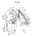
- Figure 1 is a general perspective view of a stand mechanism for a medical optical equipment, embodying the present invention;
- Figure 2 is a schematic side elevation showing the weight balancing system of the stand mechanism of Fig. 1;
- Figure 3 is a schematic side elevation as viewed in the direction of an arrow III in Fig. 2;
- Figure 4 is a diagrammatic illustration of assistance in explaining the operation of a parallel linkage in adjusting the observation angle of a medical optical equipment in a plane including the parallel linkage;
- Figure 5 is a fragmentary perspective view of a mechanism for swinging a counterweight according to the turning motion of a swivel plate in a horizontal plane;
- Figure 6 is a schematic plan view of assistance in explaining the motion of the stand mechanism of Fig. 1 in moving the medical optical equipment in longitudinal directions;
- Figure 7 is a schematic plan view of assistance in explaining the motion of the stand mechanism of Fig. 1 in moving the medical optical equipment in lateral directions;
- Figure 8 is a side elevation of the medical optical equipment held in a vertical position;
- Figures 9(a) to 9(c) are side elevations showing processes of changing the position of the medical optical equipment from a vertical position to a 45°-inclined position; and
- Figures 10(a) to 10(c) are side elevations showing processes of changing the position of the medical optical equipment from a vertical position to a 90°-inclined position.
- A stand mechanism for supporting a medical optical equipment, in a preferred embodiment, according to the present invention will be described hereinafter with reference to the accompanying drawings.
- First the constitution of the stand mechanism is described, and then the operation of the stand mechanism will be described.
- A
center shaft 21 is supported rotatably in bearings in aninclined holding unit 22. The front end (an end projecting in a direction indicated by an arrow A) of thecenter shaft 21 is machined to form a plate-shaped portion.Parallel links parallel linkage 25 are joined pivotally at the respective base ends 26 thereof to the plate-shaped portion of thecenter shaft 21. - A swivel plate (swivel member) 29 as a supporting member is joined pivotally to the
extremity 27 of theparallel linkage 25 for turning motion about anaxis 28 of rotation in a horizontal plane. A firstswivel plate 30 is joined pivotally to the free end of theswivel plate 29 with apivot shaft 31 for turning motion on thepivot shaft 31 in a horizontal plane. A secondswivel plate 32 is joined pivotally to the free end of the firstswivel plate 30 with apivot shaft 33 for turning motion in a horizontal plane. A suspendingarm 35 is held by the secondswivel plate 32, and a surgical microscope 34 (medical optical equipment) is held pivotally on the suspendingarm 35 directly below the secondswivel plate 32 so as to be turnable about anaxis 36 of rotation between a vertical position, a 45°-inclined position where thesurgical microscope 34 is inclined at an angle of 45° and a 90°-inclined position where the surgical microscope is inclined at an angle of 90°. The focus f of thesurgical microscope 34 stays always on a vertical line S passing theaxis 28 of rotation regardless of the position of the surgical microscope, which will be described in detail afterward. Moreover, since the focus f of thesurgical microscope 34 is positioned on the extension L of a straight line connecting thebase ends 26 of theparallel linkage 25 aligned with the extension of the center axis ofcenter shaft 21, the position of the focus f remains unchanged when the parallel linkage is transformed. Ahandle 37 is provided for moving (swinging) thesurgical microscope 34.Fixtures 38 are provided respectively at the base end and front end of theswivel plate 29 to change the position of thehandle 37 according to the position of the operator. - A pnedulous first counterweight W1 is suspended by a
swing bar 40 from the rear end (an end projecting in a direction indicated by an arrow B) of thecenter shaft 21 so as to be able to swing on apivot shaft 39. An adjustinghandle 41 is associated with the first counterweight W1 to adjust the vertical position of the first counterweight W1. The root portion of theswing bar 40 are covered with acover 42. The first counterweight W1 and a second counterweight W2 are covered with anothercover 46. - The
upper end 43 of theswing bar 40 and theparallel linkage 25 are interconnected by a connectingbar 44 to interlock theparallel linkage 25 and the first counterweight W1. Thus, the first counterweight W1 counterbalances the inclusive weight of thesurgical microscope 34 and theparallel linkage 25, and the rotatory moment of theparallel linkage 25 with respect to the center axis of thecenter shaft 21. Since thecenter shaft 21 is inclined at an angle α to a horizontal line, the first counterweight W1 and the associated parts are excluded from an operating zone, so that the sufficiently wide and free operating zone can be secured for the operator. - The second counterweight W2 is connected by another
swing bar 45 to the middle of theswing bar 40 suspending the first counterweight W1. The second counterweight W2 is able to swing in a vertical plane to the front and rear together with first counterweight W1 and is able to be swung in a horizontal plane by a mechanism which will be described afterward. That is, the base end of theswing bar 45 for the second counterweight W2 is fixed to apivot shaft 47 which is coaxial with theswing bar 40, and the second counterweight W2 moves along a semicircular path behind thepivot shaft 47. Thepivot shaft 47 is interlocked with arotary disk 49 provided near the rear end of thecenter shaft 21 through a pair ofbevel gears 48 respectively having axes of rotation perpendicular to each other.Disks disk 49, are provided rotatably respectively near thebase ends 26 of theparallel linkage 25, the articulatedportion 50 of theparallel linkage 25 and theextremity 27 of theparallel linkage 25. One of thebevel gears 48 and thedisks link bars 54 to transmit a torque therethrough. Thedisk 53 provided near theextremity 27 of theparallel linkage 25 is interlocked with theswivel plate 29 by a pair ofbevel gears 55. One of thebevel gears 55 is fixed to thedisk 53 and theother bevel gear 55 is fixed to apivot shaft 56 fixed to theswivel plate 29 and engages theformer bevel gear 55. Accordingly, when theswivel plate 29 is turned in a horizontal plane, the turning motion of theswivel plate 29 is transmitted through thepivot shaft 56, thebevel gears 55, thedisk 53, thedisk 52, thedisk 51, thedisk 49 thebevel gears 48 and thepivot shaft 47 in that order to theswing bar 45 holding the second counterweight W2 to turn theswing bar 45 in a horizontal plane in a direction the same as that of turning motion of theswivel plate 29, so that theswivel plate 29 and theswing bar 45 holding the second counterweight W2 extend respectively in opposite directions. Thus, the rotatory moment with respect to thecenter shaft 21 produced by the turning motion of theswivel plate 29 is counterbalanced. The position of the second counterweight W2 on theswing bar 45 can also be adjusted according to the inclination (0°, 45° or 90°) of thesurgical microscope 34 by turning anadjusting handle 57. Theslit 58 is formed in a portion of thecover 46 covering the second counterweight W2. Threenotches 59 are formed in theslit 58 at positions corresponding respectively to the three inclinations of thesurgical microscope 34. The position of the second counterweight W2 on theswing bar 45 can easily and accurately be adjusted according to the inclination of thesurgical microscope 34 by turning theadjusting handle 57 to bring a countermark on the second counterweight W2 into alignment with one of thenotches 59 corresponding to the inclination of thesurgical microscope 34. - The
holding unit 22 rotatably holding thecenter shaft 21 has a lowercylindrical part 60 rotatably supported in bearings. Thecylindrical part 60 is joined to the links of a multipleparallel linkage 61. Thus, the multipleparallel linkage 61 includes theholding unit 22 and thecylindrical part 60. The multipleparallel linkage 61 supports the inclusive weight of thecenter shaft 21 and all the components supported on thecenter shaft 21 for vertical movement. The multipleparallel linkage 61 is supported pivotally on aswivel stand shaft 63 set upright for swivel motion on abase 62. The multipleparallel linkage 61 has two pairs of upperparallel links 64 and two pairs of lowerparallel links 65 disposed one over the other. The lowerparallel links 65 are supported pivotally respectively onpivot shafts 67 attached respectively to the extremities ofprojections 66 projecting from thestand shaft 64. The upperparallel links 64 are supported pivotally above the lowerparallel links 65 respectively onpivot shafts 68 provided near the upper end of thestand shaft 63. The upperparallel links 64 and the lowerparallel links 65 are interlocked with each other by connectinglinks 69. A third counterweight W3 for counterbalancing the inclusive weight of thecenter shaft 21 and the components supported on the center shaft 21 (hereinafter referred to "upper structure") is joined to the rear ends of the lowerparallel links 65. The position of the third counterweight W3 can be adjusted by an adjustinghandle 70. If a single parallel linkage is used instead of the upper parallel linkage essentially consisting of the upperparallel links 64 having an effective length ℓ₁ (distance between the holdingunit 22 and the pivot shaft 68) and the lower parallel linkage essentially consisting of the lowerparallel links 65 having an effective length ℓ₂ (distance between thepivot shaft 68 and the third counterweight W3) to support the upper structure, the effective length of the links of the single parallel linkage is the sum of the effective lengths ℓ₁ and ℓ₂. However, the use of the upperparallel links 64 and the lowerparallel links 65 the size of the stand mechanism by the horizontal distance ℓ₃ between thepivot shafts 67 and thepivot shafts 68, which enables the stand mechanism to be formed in a compact construction. Furthermore, since the rearward projection of the third counterweight W3 is small, the third counterweight W3 will not interfere with the peripheral equipments, which is advantageous from the viewpoint of securing safety.Connecting links 71 are provided to reinforce the lower parallel linkage of thelinks 65. Thestand shaft 63 and the lowerparallel links 65 are covered with acover 72. Openings in thecover 72 for the vertical movement of the upperparallel links 64 and the third counterweight W3 are covered with bellows covers 73 and 74, respectively. Indicated at 75 is a control panel. The stand mechanism has electromagnetic clutches, not shown, provided respectively at the articulated portions and are operated selectively by means of a foot switch or the like to lock or free the components selectively. - The operation of the stand mechanism will be described hereinafter.
- As shown in Fig. 6, when the surgical microscope is pushed in a longitudinal direction, the
stand shaft 63 and thecylindrical part 60 are turned accordingly. An angle ϑ₁ or ϑ₂ of deviation of thesurgical microscope 34 with respect to theparallel linkage 25 due to the movement of thesurgical microscope 34 in the direction of the arrow B or A is compensated automatically with the turning of theswivel plate 29 holding thesurgical microscope 34 in one of the directions indicated by a double-head arrow F, and hence thesurgical microscope 34 can be translated in longitudinal directions without varying the observation angle. - When the
surgical microscope 34 is pushed in a vertical direction, the multipleparallel linkage 61 is transformed and the upper structure is moved in the same direction. Since the moment of the upper structure is counterbalanced by that of the third counterweight W3, the upper structure can easily be moved weightlessly in vertical directions. - As shown in Fig. 7, when the
surgical microscope 34 is pushed in a lateral direction, thestand shaft 63 and thecylindrical part 60 turn accordingly. Since the angle of deviation of thesurgical microscope 34 with respect to theparallel linkage 25 attributable to the longitudinal movement of thesurgical microscope 34 is compensated automatically with the turning of theswivel plate 29 holding thesurgical microscope 34 in one of the directions of the double-head arrow F, thesurgical microscope 34 can be translated in lateral directions without varying the observation angle. - Since the focus f of the
surgical microscope 34 is on the extension L of the straight line connecting the base ends 26 of theparallel linkage 25, namely, on the extension of the center axis of thecenter shaft 21, the focus f remains fixed at the original position when theparallel linkage 25 is transformed. Accordingly, the observation angle can optionally be adjusted in a plane including theparallel linkage 25. When theparallel linkage 25 is transformed, both the first counterweight W1 and the second counterweight W2 are caused to swing. Therefore, the inclusive weight of thesurgical microscope 34 and theparallel linkage 25 is counterbalanced by the first counterweight W1 and the second counterweight W2 to automatically maintain the balance of weight. The position of the first counterweight W1 on theswing bar 45 must be adjusted by means of the adjustinghandle 41 according to the weight of accessories, such as a microscope for the assistant and a video camera, mounted additionally on thesurgical microscope 34. - When the
surgical microscope 34 is turned about the center axis of thecenter shaft 21, theparallel linkage 25 is turned about the center axis of thecenter shaft 21 in the same direction, and hence the first counterweight W1 and the second counterweight W2 are turned in the same direction together with theswing bar 40. Accordingly, the balance of weight is maintained and hence thesurgical microscope 34 is positioned stationary at an optional position. - Since the
swivel plate 29 is capable of swivel motion in a horizontal plane, thesurgical microscope 34 can be turned around thehead 76 of the patient in directions of the double-head arrow F. When theswivel plate 29 is deviated from the extension of theparallel linkage 25, for example, when theswivel plate 29 is turned to a position where theswivel plate 29 extend perpendicularly to the extension of theparallel linkage 25, theswing bar 45 holding the second counterweight W2 is turned through thedisks swing bar 45 extends in the opposite direction. Accordingly, the balance of weight is maintained and hence thesurgical microscope 34 will not turn automatically about the center axis of thecenter shaft 21 further in directions of the double-head arrow E. - Furthermore, since the inclination of the
swing bar 40 holding the second counterweight W2 is always the same as that of thesurgical microscope 34 owing to the functions of theparallel linkage 25 and the connectingarm 44, the second counterweight W2 functions perfectly in maintaining the balance of weight regardless of the position of theswivel plate 29, and hence the balance of weight with respect to the directions of turning of thecenter shaft 21 is never destroyed. - Still further, since the second counterweight W2 swings behind the
pivot shaft 47 without varying the center of gravity of the upper structure, the counterbalancing function of the third counterweight W3 is maintained constantly. - In some cases, the observation angle of the
surgical microscope 34 needs to be changed through a large angle depending on the position of the operative field. For example, an encephalic surgical operation includes the operation of the parietal region of thehead 76 and the operation of the temporal region of thehead 76. This stand mechanism is provided with thefirst swivel plate 30 and thesecond swivel plate 32 to enable the change of the observation angle in a wide angular range. - Both the
first swivel plate 30 and thesecond swivel plate 32 are folded below theswivel plate 29 so as to extend toward theaxis 28 of rotation of theswivel plate 29 as shown in Fig. 8. - First, the
surgical microscope 34 is tilted from the vertical position through an angle of 45° about theaxis 36 of rotation (Fig. 9(a)). In this state, the focus f′ is located on a vertical line at a distance ℓ₅ from the vertical line S on which the focus f is located when thesurgical microscope 34 is in a vertical position and at a distance ℓ₄ from the center axis of thepivot shaft 33. The distance ℓ₅ is exactly twice the distance ℓ₄. Accordingly, when thesecond swivel plate 32 is turned through an angle of 180° on thepivot shaft 33, the focus f′ is located on the vertical line S (Fig. 9(b)). Then, when theswivel plate 29 is turned through an angle of 180° about theaxis 28 of rotation, the focus f′ remains on the vertical line S and the operator is able to observe the operative field through thesurgical microscope 34 from the same position, notwithstanding thesurgical microscope 34 is tilted at an inclination of 45° (Fig. 9(c)). Accordingly, the focus f′ can be brought to the original position of the focus f by slightly moving thesurgical microscope 34 in a vertical direction by a lifting mechanism, not shown, incorporated into thesurgical microscope 34. -
- The
surgical microscope 34 in a vertical position is turned through an angle of 90° about theaxis 36 of rotation (Fig. 10(a)). In this state, the focus f′ is located on a vertical line at a distance ℓ₆ from the vertical line S and at a distance ℓ₇ from the center axis of thepivot shaft 31. The distance ℓ₆ is exactly twice the distance ℓ₇. Accordingly, the focus f′ can be located on the vertical line S by turning thefirst swivel plate 30 through an angle of 180° on the pivot shaft 31 (Fig. 10(b)). Then, when theswivel plate 29 is turned through an angle of 180° about theaxis 28 of rotation, similarly to the case of 45°-inclined position, the focus f′ remains on the vertical line S and the operator is able to observe the operative field through thesurgical microscope 34 from the same position, notwithstanding thesurgical microscope 34 is tilted at an inclination of 90° (Fig. 10(c)). - Although the multiple
parallel linkage 61 of the stand mechanism in this embodiment is a two-unit parallel linkage, the multiple parallel linkage may be a three-unit parallel linkage or a multiple parallel linkage having more than three units. Furthermore, although the invention has been described as applied to supporting a surgical microscope as an exemplary medical optical equipment, the present invention is applicable to supporting various medical equipments such as a medical laser equipment. Still further, although the stand mechanism in this embodiment is a floor type stand mechanism, the present invention is applicable also to a suspension stand mechanism for the same function. - The stand mechanism for a medical optical equipment, according to the present invention provides the following effects.
- (a) Since the inclusive weight of the optical equipment and the parallel linkage, and the rotatory moment of the parallel linkage with respect to the center axis of the center shaft are counterbalanced by the pendulous counterweights, the stand mechanism is formed in a simple construction and is able to operate smoothly in a satisfactory balance of weight without generating noises and squeak. The employment of the rotary center shaft eliminates the need of a counterweight for balancing the weight of the parallel linkage with respect to the turning direction and simplifies the construction of the stand mechanism.
- (b) Since the rotatory moment with respect to the axis of the center shaft resulting from the turning motion of the supporting unit is counterbalanced by the counterweight, the balance of weight about the center shaft is maintained when the supporting unit supporting the heavy medical optical equipment is turned in a horizontal plane and the medical optical equipment can be stopped at any desired position.
- (c) Since the holding unit is supported for vertical movement on the extremity of the uppermost parallel linkage of the multiple parallel linkage, and the counterweight for counterbalancing the weight of the holding unit is provided on the rear end of the lowermost parallel linkage of the multiple parallel linkage, the upper structure can easily be moved vertically. Moreover, the stand mechanism has a good appearance and, since the counterweight is not projected backward, the counterweight will not interfere with the operator and the peripheral equipments, which is advantageous from the viewpoint of safety.
- (d) Since the focus of the optical equipment in the 45°-inclined position or in the 90°-inclined position can be located at a position where the focus is located when the optical equipment is in the vertical position by turning the first swivel plate or the second swivel plate through an angle of 180° in a horizontal plane, the medical optical equipment can be used at an optimum observation angle. Moreover, since the focus moves along the same vertical line, the medical optical equipment can quickly be focused remarkably reducing time necessary for a surgical operation.
Claims (5)
a parallel linkage supporting an optical equipment on the extremity thereof;
a rotary center shaft having one end supporting the parallel linkage at the base end of the same; and
a pendulous counterweight suspended for swing motion in a vertical plane from the other end of the rotary center shaft;
characterized in that the parallel linkage and the counterweight are interlocked so that the inclusive weight of the optical equipment and the parallel linkage and the rotatory moment of the parallel linkage with respect to the center axis of the center shaft are counterbalanced by the counterweight.
a parallel linkage holding a swivel member on the extremity thereof to support an optical equipment;
a rotary center shaft having one end supporting the parallel linkage at the base end of the same thereon; and
a pendulous counterweight supported for swing motion in a horizontal plane on the other end of the center shaft;
characterized in that the swivel member and the counterweight are interlocked so that a rotatory moment with respect to the center axis of the center shaft is counterbalanced by the counterweight.
an upper structure including a parallel linkage to support an optical equipment for movement maintaining the equilibrium of weight; and
a multiple parallel linkage comprising a plurality of parallel links disposed one over another;
characterized in that the upper structure is supported for vertical movement on one end of the uppermost link of the multiple parallel linkage, and a counterweight for counterbalancing the weight of the upper structure is provided on one end of the lowermost link of the multiple parallel linkage.
an arm;
a holding unit attached to the extremity of the arm;
a first swivel plate supported for turning in a horizontal plane on the supporting unit;
a second swivel plate supported for turning in a horizontal plane about an eccentric center on the first swivel plate; and
an optical equipment suspended from the second swivel plate at the eccentric center so as to be positioned in a vertical position, an inclined position inclined at an angle of 45° with respect to a vertical direction and an inclined position inclined at an angle of 90° with respect to a vertical direction;
characterized in that when the first swivel plate or the second swivel plate is turned through an angle of 180° in a horizontal plane, the focus of the optical equipment stays always on a vertical line on which the focus of the optical equipment stays when the optical equipment is in a vertical position, regardless of the inclination of the optical equipment.
a parallel linkage;
a rotary holding unit provided on the parallel linkage;
a swivel unit having first and second swivel plates capable of turning each in a horizontal plane and supporting an optical equipment and supported on the rotary holding unit;
a rotary center shaft having one end supporting the parallel linkage at the base end of the same;
a first counterweight supported on the other end of the center shaft so as to counterbalance the inclusive weight of the optical equipment and the parallel linkage and the rotatory moment of the parallel linkage with respect to the center axis of the center shaft;
a second counterweight supported on the other end of the center shaft so as to counterbalance the rotatory moment of the supporting unit with respect to the center axis of the center shaft;
a multiple parallel linkage supporting at one end thereof the center shaft for vertical movement;
a third counterweight provided on the other end of the multiple parallel linkage so as to counterbalance a weight loaded on the center shaft;
characterized in that the focus of the optical equipment in the 45°-inclined position or in the 90°-inclined position stays on the same vertical line on which the focus stays when the optical equipment is in the vertical position by turning the first swivel plate or the second swivel plate through an angle of 180° in a horizontal plane, and the focus of the optical equipment stays on the extension of the center axis of the center shaft.
Applications Claiming Priority (4)
| Application Number | Priority Date | Filing Date | Title |
|---|---|---|---|
| JP134504/87 | 1987-05-29 | ||
| JP13450487 | 1987-05-29 | ||
| JP161249/87 | 1987-06-30 | ||
| JP62161249A JPS6456409A (en) | 1987-05-29 | 1987-06-30 | Stand device for medical optical machinery |
Publications (2)
| Publication Number | Publication Date |
|---|---|
| EP0293227A2 true EP0293227A2 (en) | 1988-11-30 |
| EP0293227A3 EP0293227A3 (en) | 1990-07-11 |
Family
ID=26468605
Family Applications (1)
| Application Number | Title | Priority Date | Filing Date |
|---|---|---|---|
| EP88304835A Withdrawn EP0293227A3 (en) | 1987-05-29 | 1988-05-27 | Stand mechanism for a medical optical equipment |
Country Status (4)
| Country | Link |
|---|---|
| US (1) | US4867405A (en) |
| EP (1) | EP0293227A3 (en) |
| JP (1) | JPS6456409A (en) |
| KR (1) | KR880014394A (en) |
Cited By (5)
| Publication number | Priority date | Publication date | Assignee | Title |
|---|---|---|---|---|
| EP0451364A1 (en) * | 1990-04-11 | 1991-10-16 | Mitaka Kohki Co., Ltd. | Counterbalanced parallel linkage supporting mechanism |
| EP0552524A1 (en) * | 1992-01-17 | 1993-07-28 | Sahara, Kesanori | Stand apparatus for medical optical instrument |
| EP0917859A1 (en) * | 1997-11-14 | 1999-05-26 | Medsys S.A. | Apparatus for operating chrurgical instruments |
| EP2946759A1 (en) | 2014-05-19 | 2015-11-25 | The University of Dundee | Medical equipment support system fitted between floor and ceiling |
| EP2957272A1 (en) | 2014-05-19 | 2015-12-23 | The University of Dundee | Floor-based medical equipment support system |
Families Citing this family (24)
| Publication number | Priority date | Publication date | Assignee | Title |
|---|---|---|---|---|
| JP3011949B2 (en) * | 1989-08-23 | 2000-02-21 | 株式会社トプコン | Surgical microscope |
| FR2664989B1 (en) * | 1990-07-18 | 1992-10-30 | Dm Dev Sa | DEVICE FOR SUPPORTING AND POSITIONING A MICROSCOPE. |
| DE9013260U1 (en) * | 1990-09-19 | 1990-11-22 | Fa. Carl Zeiss, 7920 Heidenheim | Carrying device with weight compensation for a surgical microscope |
| US5203322A (en) * | 1991-09-03 | 1993-04-20 | Pierre Isabelle | Support mechanism for treatment device |
| JPH066136B2 (en) * | 1991-12-25 | 1994-01-26 | 佐原 今朝徳 | Stand equipment for medical optical equipment |
| DE4202922A1 (en) * | 1992-02-01 | 1993-08-05 | Zeiss Carl Fa | MOTORIC TRIPOD |
| US5253106A (en) * | 1992-03-20 | 1993-10-12 | Amarel Precision Instruments, Inc. | Oblique viewing system for microscopes |
| DE9205870U1 (en) * | 1992-05-06 | 1992-09-17 | J.D. Möller Optische Werke GmbH, 2000 Wedel | Microscope for microsurgery |
| US5435515A (en) * | 1992-09-15 | 1995-07-25 | Garrett W. Brown | Adustable, iso-elastic support apparatus |
| JP2825721B2 (en) * | 1992-12-28 | 1998-11-18 | 三鷹光器株式会社 | Medical optical equipment stand device |
| DE4416178B4 (en) * | 1993-05-07 | 2007-11-08 | Olympus Optical Co., Ltd. | Surgical microscope |
| US5579071A (en) * | 1994-03-21 | 1996-11-26 | Garrett W. Brown | Camera stabilizing support |
| US5825536A (en) * | 1994-09-12 | 1998-10-20 | Olympus Optical Co., Ltd. | Surgical microscope unit |
| US5642220A (en) * | 1994-09-16 | 1997-06-24 | Kleinberg; Larry K. | Microscope balance compensator |
| JP2004209096A (en) * | 2003-01-07 | 2004-07-29 | Olympus Corp | Medical instrument holding device |
| JP4270889B2 (en) * | 2003-01-15 | 2009-06-03 | オリンパス株式会社 | Medical instrument holding device |
| US20050052531A1 (en) * | 2003-09-04 | 2005-03-10 | Chapman/Leonard Studio Equipment | Stabilized camera platform system |
| JP4504081B2 (en) * | 2004-04-27 | 2010-07-14 | 三鷹光器株式会社 | Weight balance switch structure of surgical microscope stand device |
| US7516924B2 (en) * | 2005-03-28 | 2009-04-14 | Compview Corporation | Articulated boom for positioning video and medical equipment in hospital operating rooms |
| JP4903917B1 (en) * | 2010-06-10 | 2012-03-28 | オリンパスメディカルシステムズ株式会社 | Endoscope holding device |
| JP6097623B2 (en) * | 2013-04-01 | 2017-03-15 | 三鷹光器株式会社 | Auxiliary arm mounting structure of stand device |
| CN106572892B (en) * | 2014-08-01 | 2020-04-14 | 索尼奥林巴斯医疗解决方案公司 | Medical observation device |
| KR102202403B1 (en) * | 2015-11-12 | 2021-01-14 | 한국전자통신연구원 | stand assembly for supporting hair implanter |
| CN105371069B (en) * | 2015-12-16 | 2017-12-19 | 连云港天诺光学仪器有限公司 | A kind of position adjusting mechanism of ophthalmology workbench rocking arm |
Family Cites Families (15)
| Publication number | Priority date | Publication date | Assignee | Title |
|---|---|---|---|---|
| US3475075A (en) * | 1964-03-30 | 1969-10-28 | William Stone Jr | Instruments provided with optical systems and means for adjusting their optical axes |
| CH482439A (en) * | 1968-02-20 | 1969-12-15 | Contraves Ag | Observation device |
| CH526069A (en) * | 1971-01-14 | 1972-07-31 | Contraves Ag | Adjustable tripod with an optical observation device |
| CH548568A (en) * | 1972-08-18 | 1974-04-30 | Contraves Ag | CARRYING DEVICE WITH AN OPTICAL OBSERVATION DEVICE. |
| US3891301A (en) * | 1972-08-18 | 1975-06-24 | Contraves Ag | Adjustable support or stand for an optical observation instrument |
| DE2311257A1 (en) * | 1973-03-07 | 1974-09-12 | Moeller J D Optik | MICROSURGICAL UNIT |
| CH559957A5 (en) * | 1973-06-18 | 1975-03-14 | Contraves Ag | |
| DE2745883A1 (en) * | 1977-10-12 | 1979-04-19 | Siemens Ag | X-RAY EXAMINER |
| DE7930126U1 (en) * | 1979-07-24 | 1980-01-24 | Contraves Ag, Zuerich (Schweiz) | TRIPOD FOR AN OPTICAL OBSERVATION DEVICE |
| GB2091836B (en) * | 1981-01-26 | 1985-06-12 | Nat Res Dev | Pantograph linkage system |
| IT1155273B (en) * | 1982-02-05 | 1987-01-28 | Bisiach & Carru | MULTI-AXIS INDUSTRIAL ROBOT WITH FIXED-HEAD HEAD |
| US4551058A (en) * | 1983-07-20 | 1985-11-05 | Robotics, Inc. | Low cost articulating/articulating and rotating wrist mechanism for automatic machine tool and automatic machine tool employing the same |
| ATE47218T1 (en) * | 1985-05-13 | 1989-10-15 | Contraves Ag | SUPPORT DEVICE FOR AN OPTICAL OBSERVATION DEVICE. |
| US4668057A (en) * | 1985-05-28 | 1987-05-26 | Kleinberg Larry K | Counter-balancing microscope assembly |
| US4741607A (en) * | 1986-03-17 | 1988-05-03 | Contraves Ag | Supporting device for an optical observation instrument |
-
1987
- 1987-06-30 JP JP62161249A patent/JPS6456409A/en active Pending
-
1988
- 1988-05-19 US US07/195,753 patent/US4867405A/en not_active Expired - Lifetime
- 1988-05-27 EP EP88304835A patent/EP0293227A3/en not_active Withdrawn
- 1988-05-27 KR KR1019880006258A patent/KR880014394A/en not_active Withdrawn
Cited By (7)
| Publication number | Priority date | Publication date | Assignee | Title |
|---|---|---|---|---|
| EP0451364A1 (en) * | 1990-04-11 | 1991-10-16 | Mitaka Kohki Co., Ltd. | Counterbalanced parallel linkage supporting mechanism |
| EP0552524A1 (en) * | 1992-01-17 | 1993-07-28 | Sahara, Kesanori | Stand apparatus for medical optical instrument |
| EP0917859A1 (en) * | 1997-11-14 | 1999-05-26 | Medsys S.A. | Apparatus for operating chrurgical instruments |
| WO1999025267A1 (en) * | 1997-11-14 | 1999-05-27 | Medsys S.A. | Device for positioning surgical instruments |
| US6409735B1 (en) | 1997-11-14 | 2002-06-25 | Medsys S.A. | Device for positioning surgical instruments |
| EP2946759A1 (en) | 2014-05-19 | 2015-11-25 | The University of Dundee | Medical equipment support system fitted between floor and ceiling |
| EP2957272A1 (en) | 2014-05-19 | 2015-12-23 | The University of Dundee | Floor-based medical equipment support system |
Also Published As
| Publication number | Publication date |
|---|---|
| EP0293227A3 (en) | 1990-07-11 |
| KR880014394A (en) | 1988-12-23 |
| JPS6456409A (en) | 1989-03-03 |
| US4867405A (en) | 1989-09-19 |
Similar Documents
| Publication | Publication Date | Title |
|---|---|---|
| EP0293228A2 (en) | Stand mechanism for a medical optical equipment | |
| EP0293227A2 (en) | Stand mechanism for a medical optical equipment | |
| US5173803A (en) | Pivoting device for supporting frames for optical observation equipment | |
| US5861983A (en) | Microscope for microsurgery | |
| EP0781529B1 (en) | Automatic balancing mechanism for medical stand apparatus | |
| US5812301A (en) | Stand for optical devices | |
| CA1210048A (en) | Operating table | |
| US4497319A (en) | Laser irradiating apparatus | |
| CA1270474A (en) | Support apparatus for an optical observation device | |
| JPH0747998B2 (en) | A pedestal for holding freely positionable instruments | |
| JPS62231208A (en) | Carrier for optical observing apparatus | |
| JP2003111776A (en) | Stand | |
| US6045104A (en) | Medical stand apparatus | |
| JPH06261912A (en) | Coupling to connect operation microscope with rack | |
| US7677129B2 (en) | Multiaxis counterbalance and positioning system using a spatial linkage | |
| JP2000141251A (en) | Automatic balancing device for balancing stand | |
| US6532108B1 (en) | Operating microscope stand for X-Y displacement | |
| JP3151422B2 (en) | Microscope balance support mechanism | |
| US5242142A (en) | Counterbalanced parallel linkage supporting mechanism | |
| JP4398208B2 (en) | Observation device | |
| JPS63296742A (en) | Stand apparatus of medical optical machinery | |
| JP2693109B2 (en) | Medical optical equipment stand device | |
| JP2651213B2 (en) | Surgical microscope | |
| JPH02257945A (en) | Stand device for aerially supporting mechanical tool | |
| JPH06277230A (en) | Stand device of medical treatment optical apparatus |
Legal Events
| Date | Code | Title | Description |
|---|---|---|---|
| PUAI | Public reference made under article 153(3) epc to a published international application that has entered the european phase |
Free format text: ORIGINAL CODE: 0009012 |
|
| 17P | Request for examination filed |
Effective date: 19880804 |
|
| AK | Designated contracting states |
Kind code of ref document: A2 Designated state(s): CH DE GB IT LI |
|
| PUAL | Search report despatched |
Free format text: ORIGINAL CODE: 0009013 |
|
| AK | Designated contracting states |
Kind code of ref document: A3 Designated state(s): CH DE GB IT LI |
|
| 17Q | First examination report despatched |
Effective date: 19910306 |
|
| STAA | Information on the status of an ep patent application or granted ep patent |
Free format text: STATUS: THE APPLICATION IS DEEMED TO BE WITHDRAWN |
|
| 18D | Application deemed to be withdrawn |
Effective date: 19910717 |