EP0291676B1 - Apparatus for the isofrequential broadcasting of radio programmes, particularly in frequency modulation, along a highway - Google Patents
Apparatus for the isofrequential broadcasting of radio programmes, particularly in frequency modulation, along a highway Download PDFInfo
- Publication number
- EP0291676B1 EP0291676B1 EP88105345A EP88105345A EP0291676B1 EP 0291676 B1 EP0291676 B1 EP 0291676B1 EP 88105345 A EP88105345 A EP 88105345A EP 88105345 A EP88105345 A EP 88105345A EP 0291676 B1 EP0291676 B1 EP 0291676B1
- Authority
- EP
- European Patent Office
- Prior art keywords
- highway
- radio
- antennae
- signal
- tapping
- Prior art date
- Legal status (The legal status is an assumption and is not a legal conclusion. Google has not performed a legal analysis and makes no representation as to the accuracy of the status listed.)
- Expired
Links
- 230000003287 optical effect Effects 0.000 claims description 16
- 239000013307 optical fiber Substances 0.000 claims description 13
- 230000015654 memory Effects 0.000 claims description 10
- 238000010079 rubber tapping Methods 0.000 claims description 8
- 230000001427 coherent effect Effects 0.000 claims description 4
- 230000033001 locomotion Effects 0.000 claims description 3
- 238000006243 chemical reaction Methods 0.000 claims 1
- 238000005070 sampling Methods 0.000 claims 1
- 230000001934 delay Effects 0.000 description 9
- 239000000835 fiber Substances 0.000 description 5
- 238000011144 upstream manufacturing Methods 0.000 description 4
- 230000003111 delayed effect Effects 0.000 description 3
- 238000000034 method Methods 0.000 description 3
- 230000005540 biological transmission Effects 0.000 description 2
- 239000000969 carrier Substances 0.000 description 2
- 238000010586 diagram Methods 0.000 description 2
- 230000003595 spectral effect Effects 0.000 description 2
- 238000001228 spectrum Methods 0.000 description 2
- 238000011161 development Methods 0.000 description 1
- 238000001914 filtration Methods 0.000 description 1
- 230000001678 irradiating effect Effects 0.000 description 1
- 238000012986 modification Methods 0.000 description 1
- 230000004048 modification Effects 0.000 description 1
- 238000012545 processing Methods 0.000 description 1
- 230000005236 sound signal Effects 0.000 description 1
- 238000012360 testing method Methods 0.000 description 1
Images
Classifications
-
- H—ELECTRICITY
- H04—ELECTRIC COMMUNICATION TECHNIQUE
- H04H—BROADCAST COMMUNICATION
- H04H20/00—Arrangements for broadcast or for distribution combined with broadcast
- H04H20/65—Arrangements characterised by transmission systems for broadcast
- H04H20/67—Common-wave systems, i.e. using separate transmitters operating on substantially the same frequency
-
- G—PHYSICS
- G08—SIGNALLING
- G08G—TRAFFIC CONTROL SYSTEMS
- G08G1/00—Traffic control systems for road vehicles
- G08G1/09—Arrangements for giving variable traffic instructions
- G08G1/091—Traffic information broadcasting
- G08G1/094—Hardware aspects; Signal processing or signal properties, e.g. frequency bands
Definitions
- the present invention relates to an apparatus for the the isofrequential broadcasting of radiophonic programmes, particularly in frequency modulation, along a highway, to broadcast radiophonic programmes to radio receivers located on board vehicles travelling along said highway, without the need for changes in tuning in the radio receivers.
- the same carrier were used for two contiguous emitting antennae in order to provide continuous reception to moving radio receivers, in the regions of overlap (equisignal regions) one would obtain an audio signal severely distorted to the point of being unrecognizable.
- the signals are broadcast from each antenna with different time delays with respect to one another, due to the different transmission and processing times which the signal is subject to with regard to each antenna, and the delays in propagation to the receiver add to said different delays. This gives rise to a deformation of the radio-frequency signal which reflects in unacceptable distortions of the signal picked up in the receiver.
- the aim of the invention is therefore to provide an apparatus for the broadcasting of radiophonic programmes, particularly in frequency modulation, along a highway, such as to allow the continuous reception by radio receivers on board vehicles travelling along said highway, route, without need for changes in tuning in the receiver.
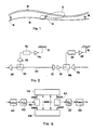
- Figure 1 shows a highway 10, with emitting antennae 12, 14, 16, arranged at intervals along the highway and having irradiation patterns with a high front-rear directivity ratio. This is indicated schematically with the preferential . lobe 11 in figure 1.
- emitting antenna any appropriate irradiating system is intended.
- optical fiber line 18 preferably of the monomodal type.
- optical fiber line refers to said line, including all the repeaters along it, in a per se known manner.
- the emitting antennae 12, 14, 16 are fed with signals tapped from the line 18, as will be described in greater detail hereinafter.
- a portion of line 18 is illustrated, constituted by an optical fiber 20, with a repeater, illustrated by way of example, comprising an optical receiver 22, for example of the PINFET type, per se known, adapted to demodulate the signal carried on the optical signal in the fiber to obtain an electric signal, an amplifier 24 adapted to amplify said electric signal obtained from the demodulation, and a laser transmitter 26, also per se known, adapted to receive the amplified electric signal and to modulate it on an optical carrier which is introduced in the fiber.
- the optical fiber line comprises several repeaters of this type, distributed along the line at intervals which depend on the attenuation of the fiber, as is known in the field.
- the head of the line 18 is fed by an initial optical transmitter 28, which is driven by the radio-frequency signal to be transmitted, for example a 100 MHz signal with maximum modulation deviation of ⁇ 75 KHz, and modulates it on an optical carrier in a per se known manner.
- an initial optical transmitter 28 which is driven by the radio-frequency signal to be transmitted, for example a 100 MHz signal with maximum modulation deviation of ⁇ 75 KHz, and modulates it on an optical carrier in a per se known manner.
- optical couplers are furthermore inserted in the optical fiber line.
- One coupler is shown by way of example at 30, to tap a fraction of the optical power flowing in the fiber and to apply it to an optical receiver 32, similar to receiver 22.
- the electric output signal of optical receiver 32 which is the radio-frequency signal to be transmitted, is delayed by a predetermined time delay, described hereinafter, in a delay device 34, also described hereinafter.
- the delayed radio-frequency signal which leaves the delay device 34 is applied to a radio-frequency amplifier 36, which feeds the emitting antenna 12.
- the signal is preferably tapped from the line by a hybrid coupler 38 inserted downstream with respect to the radio-frequency amplifier 24.
- the signal thus tapped which is the radio-frequency signal, is applied to a delay device 40, from which it goes to a radio-frequency power amplifier 42 which feeds the emitting antenna 14.
- the transmission of the two antennae is made coherent by appropriately calibrating the delays introduced in the feeds to said antennae.
- T1 is the time required by the signal to travel through the portion of optical fiber line between two adjacent antennae
- T2 is the time of propagation from the antenna upstream with respect to the equisignal region
- T3 is the propagation time from the antenna downstream with respect to the equisignal region with the signal of the upstream antenna
- the delay for all the antennae are determined, and are found to be increasing from the last antenna going upstream towards the first.
- a vehicle equipped with a radioreceiver, and moving along the highway between one antenna and the next one, will first receive in a prevalent manner the signal of a single antenna.
- the signal of the other antenna also becomes appreciable, the two signals, due to what has been described above, will be substantially coherent, and reception will still be good.
- the vehicle will definitely enter the field of the second antenna, while the signal of the first one will become negligible. This situation repeats for all the successive antennae, and in practice the radio receiver on board the vehicle will have continuous reception despite its movements.
- the inventors have determined, from practical tests, that the difference in delay of the modulation in critical points must be preferably smaller than 5 usec. This condition can be met by adjusting the delays of the signal at the various antennae as described above.
- each emitting antenna has a high front-rear directivity ratio in a direction longitudinal to the highway.
- This not only has the purpose of limiting the power to be irradiated, for a given service level on the highway, but most of all, according to the invention, said directivity reduces the extension of the region of confusion between the signals of two successive antennae, that is to say of the region where the intensities of the two signals are comparable, and therefore the picked up signal is more distorted.
- the antennae are isotropic, the overlap region is equidistant from the two antennae, with gradients of intensity of the signals which cross with low inclination.
- the two signals have an approximately equal intensity for a long region.
- the intensity gradient of the signal received rearwards is very steep, and said signal rapidly becomes negligible with respect to the other.
- the overlap region is much less extended.
- a delay device of this type can be provided for example with surface wave devices.
- the delay device comprises a frequency converter 50 which converts the RF signal at 2 MHZ.
- the 2 MHz signal is sampled at a 5-MHz rate and applied to an analogic/digital converter 52, to supply, again at a 5 MHz rate, 8-bit words which are alternately written by a write circuit 54 in successive addresses of one or the other of two RAM memories 56 and 58.
- a read circuit 60 alternately reads one word from one of the two memories 56 and 58, again at a 5 MHz rate, every time from an address backspaced by a desired offset with respect to the current write address.
- the offset is chosen so that the readout always occurs on the one of the memories 56 and 58 on which writing is not occurring, so as to avoid disastrous interferences.
- the words read in succession are applied to a digital/analogic converter 62, the output whereof, after filtering (not shown), is reconverted in frequency in a converter 64 to reobtain a radio-frequency signal which is a replica of the signal in input to the converter 50, delayed by a time which depends on the offset in the readout of the memories 56 and 58 by the read circuit 60.
- the offset may be varied within arbitrary limits, depending only on the size of the memories, it is possible to obtain arbitrary delays of the RF signal.
- the highway comprises tunnels
- broadcasting in the tunnel occurs by arranging along the ceiling of the tunnel a slit cable or similar leaking cable, according to known methods.
- the slit cable is to be considered, for the purposes of the invention, as a particular type of emitting antenna, to which the same feeding rules described above are applied.
- the cable will be fed at its input as described with reference to figure 2, and the same considerations on signal delays, both with reference to the antenna immediately preceding the beginning of the tunnel and with reference to the successive antenna at the exit of the tunnel, are valid therefor, it being evident that, to cover the portion of highway at the exit from the tunnel, an emitting antenna, also subject to the same rules described above, must be prearranged immediately adjacent to the exit of the tunnel.
Landscapes
- Engineering & Computer Science (AREA)
- Signal Processing (AREA)
- Multimedia (AREA)
- Physics & Mathematics (AREA)
- General Physics & Mathematics (AREA)
- Variable-Direction Aerials And Aerial Arrays (AREA)
- Near-Field Transmission Systems (AREA)
Description
- The present invention relates to an apparatus for the the isofrequential broadcasting of radiophonic programmes, particularly in frequency modulation, along a highway, to broadcast radiophonic programmes to radio receivers located on board vehicles travelling along said highway, without the need for changes in tuning in the radio receivers.
- To broadcast a same radiophonic programme to a territory greater than that irradiatable with a single emitting antenna, it is known to segment the territory into a plurality of contiguous areas, each served by a different emitting antenna, and to broadcast from the various antennae the same programme on carriers at different frequencies, the programme being transmitted to the broadcasting site for example by means of a radio link. The user tunes his receiver to the one of the nearby antennae which gives him the best reception.
- The above described arrangement is satisfactory for broadcasting to domestic, and therefore stationary, radio receivers, which can be tuned once and for all to the station ensuring the best reception, while, in the case of radio receivers installed on board vehicles moving along a highway, the reception conditions are extremely variable, and would require that the receiver be tuned to a new station every few miles of travel.
- If the same carrier were used for two contiguous emitting antennae in order to provide continuous reception to moving radio receivers, in the regions of overlap (equisignal regions) one would obtain an audio signal severely distorted to the point of being unrecognizable. In fact, in general the signals are broadcast from each antenna with different time delays with respect to one another, due to the different transmission and processing times which the signal is subject to with regard to each antenna, and the delays in propagation to the receiver add to said different delays. This gives rise to a deformation of the radio-frequency signal which reflects in unacceptable distortions of the signal picked up in the receiver.
- To this distortion there furthermore adds another, due to another cause of spectral deformation, linked to the different depth of modulation which will occur in general in the signals broadcast by different transmitters. As is evident to the expert in the field, on the basis of the mathematical description of the frequency modulation process, a same modulating signal generates in the carrier spectral lines at different frequencies according to the depth of modulation. Thus the superimposition of the related spectra gives rise to a total spectrum with such strong anomalies as to cause severe and uncontrollable distortions of the picked up signal. The inventors have determined, on this subject, that for an acceptable reception the difference in modulation depth must be smaller than 0.2 dB, and preferably than 0.1 dB.
- The aim of the invention is therefore to provide an apparatus for the broadcasting of radiophonic programmes, particularly in frequency modulation, along a highway, such as to allow the continuous reception by radio receivers on board vehicles travelling along said highway, route, without need for changes in tuning in the receiver.
- The abovesaid aim is achieved by the invention, together with other objects and advantages, such as will become apparent hereinafter, with an apparatus for the isofrequential radiobroadcasting of radiophonic programmes, particularly in frequency modulation, along a highway, aimed at radio receivers in motion along said highway, characterized in that it comprises:
- a) a plurality of emitting antennae arranged at intervals along said highway, and respective radio-frequency amplifiers connected to feed said antennae;
- b) an optical fiber line adjacent to said highway, fed at one end by an optical transmitter driven by a radiofrequency signal to be broadcast;
- c) means for tapping the radio-frequency signal from the optical fiber line at each radio-frequency amplifier; and
- d) means for delaying the radio-frequency signal having their input connected to the output of said tapping means and the output connected to said radio-frequency amplifiers; the delay introduced by each of said delay means being such that in the equisignal region between every two adjacent emitting antennae the broadcast signal is substantially coherent.
- A preferred embodiment of the invention will now be described, given by way of non-limitative example, with reference to the accompanying drawings, wherein:
- figure 1 is a schematic view, not to scale, of a highway with distributed emitting antennae;
- figure 2 is a partial block diagram of a broadcasting apparatus according to the invention;
- figure 3 is a diagram of a preferred delay device used in the apparatus according to the invention.
- Figure 1 shows a
highway 10, with emittingantennae - Along the highway there runs an
optical fiber line 18, preferably of the monomodal type. Theline 18, as will be described in greater detail hereinafter, is constituted by an optical fiber with repeaters (not shown in figure 1) inserted at intervals, intended to compensate the attenuation to which the signal which runs in the fiber is subject, typically of the order of 0.5 dB per kilometer of line. In the continuation of the description and in the claims, the expression "optical fiber line" refers to said line, including all the repeaters along it, in a per se known manner. Theemitting antennae line 18, as will be described in greater detail hereinafter. - In figure 2, a portion of
line 18 is illustrated, constituted by anoptical fiber 20, with a repeater, illustrated by way of example, comprising anoptical receiver 22, for example of the PINFET type, per se known, adapted to demodulate the signal carried on the optical signal in the fiber to obtain an electric signal, anamplifier 24 adapted to amplify said electric signal obtained from the demodulation, and alaser transmitter 26, also per se known, adapted to receive the amplified electric signal and to modulate it on an optical carrier which is introduced in the fiber. The optical fiber line comprises several repeaters of this type, distributed along the line at intervals which depend on the attenuation of the fiber, as is known in the field. - The head of the
line 18 is fed by an initialoptical transmitter 28, which is driven by the radio-frequency signal to be transmitted, for example a 100 MHz signal with maximum modulation deviation of ± 75 KHz, and modulates it on an optical carrier in a per se known manner. - To tap the signal at the emitting antennae, optical couplers are furthermore inserted in the optical fiber line. One coupler is shown by way of example at 30, to tap a fraction of the optical power flowing in the fiber and to apply it to an
optical receiver 32, similar toreceiver 22. The electric output signal ofoptical receiver 32, which is the radio-frequency signal to be transmitted, is delayed by a predetermined time delay, described hereinafter, in adelay device 34, also described hereinafter. The delayed radio-frequency signal which leaves thedelay device 34 is applied to a radio-frequency amplifier 36, which feeds theemitting antenna 12. - Where the emitting antenna is near to an optical repeater, the signal is preferably tapped from the line by a
hybrid coupler 38 inserted downstream with respect to the radio-frequency amplifier 24. The signal thus tapped, which is the radio-frequency signal, is applied to adelay device 40, from which it goes to a radio-frequency power amplifier 42 which feeds theemitting antenna 14. - According to the invention, in order to provide an intelligible reception even in the regions of overlap between the portions of irradiation of two adjacent antennae (that is to say in the regions in which the intensities of the signals of one of the two antennae is not negligible with respect to other), the transmission of the two antennae is made coherent by appropriately calibrating the delays introduced in the feeds to said antennae. More exactly, if T1 is the time required by the signal to travel through the portion of optical fiber line between two adjacent antennae, T2 is the time of propagation from the antenna upstream with respect to the equisignal region, and T3 is the propagation time from the antenna downstream with respect to the equisignal region with the signal of the upstream antenna, the delays R1 and R2 introduced by the delay devices of the upstream antenna and of the downstream antenna must meet the relation:

- By writing a similar relation for all the antennae in succession, and imposing furthermore an arbitrary value, generally nil, for the delay for the last antenna, at the end of the optical fiber line, the delay for all the antennae are determined, and are found to be increasing from the last antenna going upstream towards the first.
- A vehicle equipped with a radioreceiver, and moving along the highway between one antenna and the next one, will first receive in a prevalent manner the signal of a single antenna. When the signal of the other antenna also becomes appreciable, the two signals, due to what has been described above, will be substantially coherent, and reception will still be good. Finally the vehicle will definitely enter the field of the second antenna, while the signal of the first one will become negligible. This situation repeats for all the successive antennae, and in practice the radio receiver on board the vehicle will have continuous reception despite its movements.
- Since a copy of the same radio-frequency signal, that is to say of the same modulated electric carrier, is fed to all the emitting antennae, it is evident that the condition described in the introduction, i.e. that the difference in modulation depth among the carriers irradiated by different antennae be contained within 0.2 dB, or preferably 0.1 dB, is certainly met.
- Furthermore, the inventors have determined, from practical tests, that the difference in delay of the modulation in critical points must be preferably smaller than 5 usec. This condition can be met by adjusting the delays of the signal at the various antennae as described above.
- As described above, each emitting antenna has a high front-rear directivity ratio in a direction longitudinal to the highway. This not only has the purpose of limiting the power to be irradiated, for a given service level on the highway, but most of all, according to the invention, said directivity reduces the extension of the region of confusion between the signals of two successive antennae, that is to say of the region where the intensities of the two signals are comparable, and therefore the picked up signal is more distorted. In fact if the antennae are isotropic, the overlap region is equidistant from the two antennae, with gradients of intensity of the signals which cross with low inclination. Thus the two signals have an approximately equal intensity for a long region. Instead, by imparting high front-rear ratios to the antennae, the intensity gradient of the signal received rearwards is very steep, and said signal rapidly becomes negligible with respect to the other. Thus the overlap region is much less extended.
- The delays introduced by the several delay devices are heavily variable, ranging from 0 to a few hundred microseconds. A delay device of this type can be provided for example with surface wave devices. With reference to figure 3, a particularly versatile embodiment of a delay device according to the invention, employing digital methods, will now be described.
- With reference to figure 3, the delay device comprises a
frequency converter 50 which converts the RF signal at 2 MHZ. The 2 MHz signal is sampled at a 5-MHz rate and applied to an analogic/digital converter 52, to supply, again at a 5 MHz rate, 8-bit words which are alternately written by awrite circuit 54 in successive addresses of one or the other of twoRAM memories read circuit 60 alternately reads one word from one of the twomemories memories analogic converter 62, the output whereof, after filtering (not shown), is reconverted in frequency in aconverter 64 to reobtain a radio-frequency signal which is a replica of the signal in input to theconverter 50, delayed by a time which depends on the offset in the readout of thememories read circuit 60. - Since the offset may be varied within arbitrary limits, depending only on the size of the memories, it is possible to obtain arbitrary delays of the RF signal.
- According to a further advantageous development of the invention, if the highway comprises tunnels, broadcasting in the tunnel occurs by arranging along the ceiling of the tunnel a slit cable or similar leaking cable, according to known methods. The slit cable is to be considered, for the purposes of the invention, as a particular type of emitting antenna, to which the same feeding rules described above are applied. In particular, the cable will be fed at its input as described with reference to figure 2, and the same considerations on signal delays, both with reference to the antenna immediately preceding the beginning of the tunnel and with reference to the successive antenna at the exit of the tunnel, are valid therefor, it being evident that, to cover the portion of highway at the exit from the tunnel, an emitting antenna, also subject to the same rules described above, must be prearranged immediately adjacent to the exit of the tunnel.
- A preferred embodiment of the invention has been described, but naturally it is susceptible of equivalent modifications and variations, obvious for the expert in the field according to the given teachings, without thereby abandoning the scope of the inventive concept.
Claims (7)
- Apparatus for the isofrequential broadcasting of radiophonic programmes, particularly in frequency modulation, along a highway (10), aimed at radio receivers in motion along said highway, characterized in that it comprises:a) a plurality of emitting antennae (12, 14) arranged at intervals along said highway, and respective radio-frequency amplifiers (36; 42) connected to feed said antennae;b) an optical fiber line (18) adjacent to said highway, fed at one end by an optical transmitter (28) driven by a radio-frequency signal to be broadcast;c) tapping (30; 38) means for tapping the radio-frequency signal from the optical fiber line at each radio-frequency amplifier; andd) delay means (34; 40) for delaying the radio-frequency signal, having their input connected to the output of said tapping means and their output connected to said radio-frequency amplifiers; the delay introduced by each of said delay means being such that in the equisignal region between every two adjacent emitting antennae the broadcast signal is substantially coherent.
- The broadcasting apparatus according to claim 1, characterized in that said tapping means for at least one of said emitting antennae consist of an optical coupler (30) inserted in series in the optical fiber line and having its derived output connected to an optical receiver (32) which drives said delay device.
- The broadcasting apparatus according to claim 1, characterized in that said tapping means for at least one of said emitting antennae consist of the arrangement in series of an optical receiver (22), an amplifier (24), a hybrid coupler (38) and an optical transmitter (26), the derived output of the hybrid coupler driving the delay means.
- A broadcasting apparatus according to one of claims 1-3, characterized in that each of said emitting antennae has a high ratio of front-rear directivity in a direction longitudinal to the highway.
- A broadcasting apparatus according to one of claims 1-3, characterized in that, where the highway extends in a tunnel, the apparatus comprises an emitting antenna constituted by a slit cable which runs along the ceiling of the gallery, and fed by said tapping means at its entrance.
- A broadcasting apparatus according to one of claims 1-5, characterized in that each of said delay means comprises:a) circuit means (50, 52) for sampling and converting the signal into digital words;b) memory means (56, 58);c) means (54) for writing said digital words in succession in successive addresses of said memory means;d) means (60) for reading said words from successive addresses of said memory means, offset by a desired offset with respect to the write addresses;e) means (62, 64) for the conversion of said words read by the readout means into analogic form.
- A broadcasting apparatus according to claim 6, characterized in that said memory means comprise two memories, said write and readout means being adapted to write and read alternately therefrom.
Applications Claiming Priority (2)
| Application Number | Priority Date | Filing Date | Title |
|---|---|---|---|
| IT2060887 | 1987-05-21 | ||
| IT20608/87A IT1205657B (en) | 1987-05-21 | 1987-05-21 | ISOFREQUENTIAL RADIO BROADCAST SYSTEM OF RADIO PROGRAMS, PARTICULARLY IN FREQUENCY MODULATION, ALONG A ROAD ROUTE |
Publications (3)
| Publication Number | Publication Date |
|---|---|
| EP0291676A2 EP0291676A2 (en) | 1988-11-23 |
| EP0291676A3 EP0291676A3 (en) | 1989-03-29 |
| EP0291676B1 true EP0291676B1 (en) | 1991-10-16 |
Family
ID=11169486
Family Applications (1)
| Application Number | Title | Priority Date | Filing Date |
|---|---|---|---|
| EP88105345A Expired EP0291676B1 (en) | 1987-05-21 | 1988-04-02 | Apparatus for the isofrequential broadcasting of radio programmes, particularly in frequency modulation, along a highway |
Country Status (3)
| Country | Link |
|---|---|
| EP (1) | EP0291676B1 (en) |
| DE (2) | DE3865520D1 (en) |
| IT (1) | IT1205657B (en) |
Families Citing this family (7)
| Publication number | Priority date | Publication date | Assignee | Title |
|---|---|---|---|---|
| FR2639492B1 (en) * | 1988-11-23 | 1994-07-29 | Autoroutes Cie Financ Indle | ISOFREQUENCY RADIO BROADCASTING METHOD AND DEVICE WITH ATTENUATED INTERFERENCE |
| FR2673784B1 (en) * | 1991-03-08 | 1993-07-02 | Autoroutes Cie Financ Indle | IMPROVEMENT ON ISOFREQUENCE NETWORKS. |
| IT1255805B (en) * | 1992-08-07 | 1995-11-16 | PROCEDURE FOR TRANSFER VIA RADIOELECTRIC BRIDGE VIDEO OF SIGNALS INTENDED FOR ISOFREQUENTIAL BROADCAST | |
| US5468638A (en) * | 1992-09-28 | 1995-11-21 | Becton, Dickinson And Company | Cell culture insert |
| FR2710010A1 (en) * | 1993-09-17 | 1995-03-24 | Sanef | Device and method for keeping the driver of a motor vehicle awake |
| DE10248685A1 (en) * | 2002-07-15 | 2004-02-05 | Prosch, Theodor, Dr. | Synchronous wave multimedia transmission network feeds high frequency signal and reference over broadband distribution network to user premises |
| DE102004016406B4 (en) * | 2004-03-26 | 2006-06-08 | Prosch, Theodor, Dr. | Digital broadcast coherent wave transmission control procedure uses broadband transmission to broadcast points with frequency set by control code |
Family Cites Families (3)
| Publication number | Priority date | Publication date | Assignee | Title |
|---|---|---|---|---|
| DE1252284B (en) * | ||||
| DE3020176A1 (en) * | 1980-05-28 | 1981-12-03 | Licentia Patent-Verwaltungs-Gmbh, 6000 Frankfurt | METHOD AND ARRANGEMENT FOR SIMULTANEOUSLY SENDING MESSAGES ON SEVERAL SAME-WAVE TRANSMITTERS |
| DE3213645A1 (en) * | 1982-04-14 | 1983-10-27 | Licentia Patent-Verwaltungs-Gmbh, 6000 Frankfurt | Common-wave radio network |
-
1987
- 1987-05-21 IT IT20608/87A patent/IT1205657B/en active
-
1988
- 1988-04-02 DE DE8888105345T patent/DE3865520D1/en not_active Expired - Lifetime
- 1988-04-02 DE DE198888105345T patent/DE291676T1/en active Pending
- 1988-04-02 EP EP88105345A patent/EP0291676B1/en not_active Expired
Also Published As
| Publication number | Publication date |
|---|---|
| IT8720608A0 (en) | 1987-05-21 |
| IT1205657B (en) | 1989-03-31 |
| DE291676T1 (en) | 1989-03-30 |
| DE3865520D1 (en) | 1991-11-21 |
| EP0291676A3 (en) | 1989-03-29 |
| EP0291676A2 (en) | 1988-11-23 |
Similar Documents
| Publication | Publication Date | Title |
|---|---|---|
| US7853197B2 (en) | Apparatus and method for reusing satellite broadcast spectrum for terrestrially broadcast signals | |
| JP2791060B2 (en) | Especially radio wave-light wave transmission system for space communication | |
| EP1139589B1 (en) | Dual band digital broadcast receiver | |
| US4363129A (en) | Method and means of minimizing simulcast distortion in a receiver when using a same-frequency repeater | |
| FR2756686B1 (en) | METHOD AND DEVICE FOR ANALOG AND DIGITAL MIXED BROADCASTING OF RADIO TRANSMISSION BROADCASTED BY THE SAME TRANSMITTER | |
| WO1995027373A1 (en) | System for providing local originating signals with direct broadcast satellite television signals | |
| EP0274650A1 (en) | Bidirectionnel information transmission system between a monitor station on the ground and a mobile station | |
| EP0291676A2 (en) | Apparatus for the isofrequential broadcasting of radio programmes, particularly in frequency modulation, along a highway | |
| CZ86998A3 (en) | Method of common transmission of digitally and analogically modulated signals of radio and/or television broadcasting and apparatus for making the same | |
| US3760278A (en) | Limited range radiocommunication system | |
| JPH04372234A (en) | Transmission power control system | |
| JP6924678B2 (en) | Transmission system | |
| BR9815180A (en) | Apparatus and method for reusing satellite broadcasting spectrum for terrestrial broadcasting signals. | |
| JPS55133148A (en) | Interference wave removal system | |
| EP0370915B1 (en) | Device and system for isofrequencial broadcasting with reduced interfrequencies | |
| DE4335345A1 (en) | Mobile base station and antenna arrangement to provide radio coverage for a tunnel | |
| US2866088A (en) | Radio communication within shielded enclosures | |
| KR100533534B1 (en) | Vehicles repeater and the method to extend broadcasting satellite signal | |
| EP0026085B1 (en) | Satellite communication system | |
| JPS634972B2 (en) | ||
| US1721627A (en) | Radio transmission system | |
| RU2166841C1 (en) | Method for transmitting and receiving stereo signal in single-sideband systems | |
| KR100244890B1 (en) | Time Division Modulation Broadband Amplifier | |
| KR950005701Y1 (en) | DACHANEL Underground Wireless Repeater | |
| JPS61289737A (en) | Re-broadcasting equipment in tunnel |
Legal Events
| Date | Code | Title | Description |
|---|---|---|---|
| PUAI | Public reference made under article 153(3) epc to a published international application that has entered the european phase |
Free format text: ORIGINAL CODE: 0009012 |
|
| AK | Designated contracting states |
Kind code of ref document: A2 Designated state(s): DE FR GB |
|
| PUAL | Search report despatched |
Free format text: ORIGINAL CODE: 0009013 |
|
| EL | Fr: translation of claims filed | ||
| AK | Designated contracting states |
Kind code of ref document: A3 Designated state(s): DE FR GB |
|
| DET | De: translation of patent claims | ||
| 17P | Request for examination filed |
Effective date: 19890508 |
|
| 17Q | First examination report despatched |
Effective date: 19910213 |
|
| GRAA | (expected) grant |
Free format text: ORIGINAL CODE: 0009210 |
|
| AK | Designated contracting states |
Kind code of ref document: B1 Designated state(s): DE FR GB |
|
| REF | Corresponds to: |
Ref document number: 3865520 Country of ref document: DE Date of ref document: 19911121 |
|
| ET | Fr: translation filed | ||
| PLBE | No opposition filed within time limit |
Free format text: ORIGINAL CODE: 0009261 |
|
| STAA | Information on the status of an ep patent application or granted ep patent |
Free format text: STATUS: NO OPPOSITION FILED WITHIN TIME LIMIT |
|
| 26N | No opposition filed | ||
| REG | Reference to a national code |
Ref country code: GB Ref legal event code: IF02 |
|
| PGFP | Annual fee paid to national office [announced via postgrant information from national office to epo] |
Ref country code: GB Payment date: 20070330 Year of fee payment: 20 |
|
| PGFP | Annual fee paid to national office [announced via postgrant information from national office to epo] |
Ref country code: DE Payment date: 20070615 Year of fee payment: 20 |
|
| REG | Reference to a national code |
Ref country code: GB Ref legal event code: PE20 Expiry date: 20080401 |
|
| PGFP | Annual fee paid to national office [announced via postgrant information from national office to epo] |
Ref country code: FR Payment date: 20070329 Year of fee payment: 20 |
|
| PG25 | Lapsed in a contracting state [announced via postgrant information from national office to epo] |
Ref country code: GB Free format text: LAPSE BECAUSE OF EXPIRATION OF PROTECTION Effective date: 20080401 |